EP3457545A1 - Segmentierte elektrische maschine - Google Patents
Segmentierte elektrische maschine Download PDFInfo
- Publication number
- EP3457545A1 EP3457545A1 EP18189093.0A EP18189093A EP3457545A1 EP 3457545 A1 EP3457545 A1 EP 3457545A1 EP 18189093 A EP18189093 A EP 18189093A EP 3457545 A1 EP3457545 A1 EP 3457545A1
- Authority
- EP
- European Patent Office
- Prior art keywords
- rotor
- electrical machine
- machine according
- balancing
- compensator
- Prior art date
- Legal status (The legal status is an assumption and is not a legal conclusion. Google has not performed a legal analysis and makes no representation as to the accuracy of the status listed.)
- Granted
Links
Images


Classifications
-
- H—ELECTRICITY
- H02—GENERATION; CONVERSION OR DISTRIBUTION OF ELECTRIC POWER
- H02K—DYNAMO-ELECTRIC MACHINES
- H02K7/00—Arrangements for handling mechanical energy structurally associated with dynamo-electric machines, e.g. structural association with mechanical driving motors or auxiliary dynamo-electric machines
- H02K7/04—Balancing means
-
- F—MECHANICAL ENGINEERING; LIGHTING; HEATING; WEAPONS; BLASTING
- F01—MACHINES OR ENGINES IN GENERAL; ENGINE PLANTS IN GENERAL; STEAM ENGINES
- F01D—NON-POSITIVE DISPLACEMENT MACHINES OR ENGINES, e.g. STEAM TURBINES
- F01D15/00—Adaptations of machines or engines for special use; Combinations of engines with devices driven thereby
- F01D15/10—Adaptations for driving, or combinations with, electric generators
-
- H—ELECTRICITY
- H02—GENERATION; CONVERSION OR DISTRIBUTION OF ELECTRIC POWER
- H02K—DYNAMO-ELECTRIC MACHINES
- H02K1/00—Details of the magnetic circuit
- H02K1/06—Details of the magnetic circuit characterised by the shape, form or construction
- H02K1/22—Rotating parts of the magnetic circuit
- H02K1/24—Rotor cores with salient poles ; Variable reluctance rotors
- H02K1/246—Variable reluctance rotors
-
- H—ELECTRICITY
- H02—GENERATION; CONVERSION OR DISTRIBUTION OF ELECTRIC POWER
- H02K—DYNAMO-ELECTRIC MACHINES
- H02K11/00—Structural association of dynamo-electric machines with electric components or with devices for shielding, monitoring or protection
- H02K11/30—Structural association with control circuits or drive circuits
-
- H—ELECTRICITY
- H02—GENERATION; CONVERSION OR DISTRIBUTION OF ELECTRIC POWER
- H02K—DYNAMO-ELECTRIC MACHINES
- H02K19/00—Synchronous motors or generators
- H02K19/02—Synchronous motors
- H02K19/10—Synchronous motors for multi-phase current
- H02K19/103—Motors having windings on the stator and a variable reluctance soft-iron rotor without windings
-
- H—ELECTRICITY
- H02—GENERATION; CONVERSION OR DISTRIBUTION OF ELECTRIC POWER
- H02K—DYNAMO-ELECTRIC MACHINES
- H02K7/00—Arrangements for handling mechanical energy structurally associated with dynamo-electric machines, e.g. structural association with mechanical driving motors or auxiliary dynamo-electric machines
- H02K7/08—Structural association with bearings
- H02K7/09—Structural association with bearings with magnetic bearings
-
- H—ELECTRICITY
- H02—GENERATION; CONVERSION OR DISTRIBUTION OF ELECTRIC POWER
- H02K—DYNAMO-ELECTRIC MACHINES
- H02K7/00—Arrangements for handling mechanical energy structurally associated with dynamo-electric machines, e.g. structural association with mechanical driving motors or auxiliary dynamo-electric machines
- H02K7/18—Structural association of electric generators with mechanical driving motors, e.g. with turbines
- H02K7/1807—Rotary generators
- H02K7/1823—Rotary generators structurally associated with turbines or similar engines
-
- F—MECHANICAL ENGINEERING; LIGHTING; HEATING; WEAPONS; BLASTING
- F01—MACHINES OR ENGINES IN GENERAL; ENGINE PLANTS IN GENERAL; STEAM ENGINES
- F01D—NON-POSITIVE DISPLACEMENT MACHINES OR ENGINES, e.g. STEAM TURBINES
- F01D5/00—Blades; Blade-carrying members; Heating, heat-insulating, cooling or antivibration means on the blades or the members
- F01D5/02—Blade-carrying members, e.g. rotors
- F01D5/027—Arrangements for balancing
-
- F—MECHANICAL ENGINEERING; LIGHTING; HEATING; WEAPONS; BLASTING
- F02—COMBUSTION ENGINES; HOT-GAS OR COMBUSTION-PRODUCT ENGINE PLANTS
- F02C—GAS-TURBINE PLANTS; AIR INTAKES FOR JET-PROPULSION PLANTS; CONTROLLING FUEL SUPPLY IN AIR-BREATHING JET-PROPULSION PLANTS
- F02C7/00—Features, components parts, details or accessories, not provided for in, or of interest apart form groups F02C1/00 - F02C6/00; Air intakes for jet-propulsion plants
- F02C7/26—Starting; Ignition
- F02C7/268—Starting drives for the rotor, acting directly on the rotor of the gas turbine to be started
-
- F—MECHANICAL ENGINEERING; LIGHTING; HEATING; WEAPONS; BLASTING
- F02—COMBUSTION ENGINES; HOT-GAS OR COMBUSTION-PRODUCT ENGINE PLANTS
- F02C—GAS-TURBINE PLANTS; AIR INTAKES FOR JET-PROPULSION PLANTS; CONTROLLING FUEL SUPPLY IN AIR-BREATHING JET-PROPULSION PLANTS
- F02C7/00—Features, components parts, details or accessories, not provided for in, or of interest apart form groups F02C1/00 - F02C6/00; Air intakes for jet-propulsion plants
- F02C7/32—Arrangement, mounting, or driving, of auxiliaries
-
- F—MECHANICAL ENGINEERING; LIGHTING; HEATING; WEAPONS; BLASTING
- F05—INDEXING SCHEMES RELATING TO ENGINES OR PUMPS IN VARIOUS SUBCLASSES OF CLASSES F01-F04
- F05D—INDEXING SCHEME FOR ASPECTS RELATING TO NON-POSITIVE-DISPLACEMENT MACHINES OR ENGINES, GAS-TURBINES OR JET-PROPULSION PLANTS
- F05D2220/00—Application
- F05D2220/30—Application in turbines
- F05D2220/32—Application in turbines in gas turbines
- F05D2220/323—Application in turbines in gas turbines for aircraft propulsion, e.g. jet engines
-
- F—MECHANICAL ENGINEERING; LIGHTING; HEATING; WEAPONS; BLASTING
- F05—INDEXING SCHEMES RELATING TO ENGINES OR PUMPS IN VARIOUS SUBCLASSES OF CLASSES F01-F04
- F05D—INDEXING SCHEME FOR ASPECTS RELATING TO NON-POSITIVE-DISPLACEMENT MACHINES OR ENGINES, GAS-TURBINES OR JET-PROPULSION PLANTS
- F05D2220/00—Application
- F05D2220/70—Application in combination with
- F05D2220/76—Application in combination with an electrical generator
- F05D2220/768—Application in combination with an electrical generator equipped with permanent magnets
-
- F—MECHANICAL ENGINEERING; LIGHTING; HEATING; WEAPONS; BLASTING
- F05—INDEXING SCHEMES RELATING TO ENGINES OR PUMPS IN VARIOUS SUBCLASSES OF CLASSES F01-F04
- F05D—INDEXING SCHEME FOR ASPECTS RELATING TO NON-POSITIVE-DISPLACEMENT MACHINES OR ENGINES, GAS-TURBINES OR JET-PROPULSION PLANTS
- F05D2260/00—Function
- F05D2260/96—Preventing, counteracting or reducing vibration or noise
-
- H—ELECTRICITY
- H02—GENERATION; CONVERSION OR DISTRIBUTION OF ELECTRIC POWER
- H02K—DYNAMO-ELECTRIC MACHINES
- H02K1/00—Details of the magnetic circuit
- H02K1/06—Details of the magnetic circuit characterised by the shape, form or construction
- H02K1/12—Stationary parts of the magnetic circuit
- H02K1/14—Stator cores with salient poles
- H02K1/146—Stator cores with salient poles consisting of a generally annular yoke with salient poles
- H02K1/148—Sectional cores
-
- H—ELECTRICITY
- H02—GENERATION; CONVERSION OR DISTRIBUTION OF ELECTRIC POWER
- H02K—DYNAMO-ELECTRIC MACHINES
- H02K2201/00—Specific aspects not provided for in the other groups of this subclass relating to the magnetic circuits
- H02K2201/15—Sectional machines
-
- H—ELECTRICITY
- H02—GENERATION; CONVERSION OR DISTRIBUTION OF ELECTRIC POWER
- H02K—DYNAMO-ELECTRIC MACHINES
- H02K2213/00—Specific aspects, not otherwise provided for and not covered by codes H02K2201/00 - H02K2211/00
- H02K2213/12—Machines characterised by the modularity of some components
-
- H—ELECTRICITY
- H02—GENERATION; CONVERSION OR DISTRIBUTION OF ELECTRIC POWER
- H02K—DYNAMO-ELECTRIC MACHINES
- H02K41/00—Propulsion systems in which a rigid body is moved along a path due to dynamo-electric interaction between the body and a magnetic field travelling along the path
- H02K41/02—Linear motors; Sectional motors
- H02K41/03—Synchronous motors; Motors moving step by step; Reluctance motors
Definitions
- the present disclosure relates to a segmented electrical machine.
- a segmented electrical machine to be mounted in a gas turbine engine or other rotating assembly.
- EP A 3035504 proposes an electrical machine having a variable reluctance rotor and an annular array of stator segments which are each configured to function, in conjunction with the rotor, as an electrical machine.
- the variable reluctance rotor can be integrated with or mounted to the radial periphery of a rotor stage, or a pair of axially spaced rotor stages, of a gas turbine engine, whereby the weight of the machine and the number of its components can be reduced relative to more conventional electrical machines associated with gas turbine engines.
- each stator segment can be individually removed or replaced, facilitating maintenance.
- FIG. 1 shows schematically a transverse cross-section through such an electrical machine 100 having a single variable reluctance rotor 101, and plural external stator segments 102. These are non-axisymmetrically distributed so that existing pipes and cables of the gas turbine engine can be accommodated in the spaces 103 between the stator segments.
- the stator segments are non-axisymmetrically distributed, they exert a radial unbalanced magnetic force (UMF) on the variable reluctance rotor when the machine is operated as a motor.
- UMF unbalanced magnetic force
- the UMF can be several orders of magnitude greater than the torque-producing forces acting in the tangential direction. As a consequence, increased shaft eccentricities and bearing friction can considerably decrease bearing life. Moreover, the UMF can serve as external excitation source for rotor vibrations such that, when close to system resonant frequencies, severe deformation can occur.
- the present disclosure aims to address the UMF in segmented electrical machines by active compensation.
- the present disclosure provides an electrical machine having:
- the compensator can compensate for a UMF with a rapid response time, and an operation that, because of the invariance of the reluctance of the rotor-to-compensator magnetic flux path, is independent of the operation of the stator segments.
- the compensator can achieve high force densities, and have a low power requirement and a high operational reliability.
- the present disclosure provides a gas turbine engine including an electrical machine according to the first aspect.
- the variable reluctance rotor can be integrated with or mounted to a rotor stage, or a pair of axially spaced rotor stages, of the gas turbine engine.
- the unbalanced force may be radial or may include a radial component.
- the unbalanced force may be axial or may include an axial component. Accordingly, the unbalanced force may include a radial component and an axial component.
- stator segments may be non-axisymmetrically distributed in the annular array. Additionally or alternatively, the stator segments may have unequal electrical loads when magnetically energized to rotate the rotor.
- The, or each, balancing segment may typically have a core structure (e.g. formed of magnetically permeable material) and a conductor winding mounted to the core structure, which conductor winding is electrically excitable to magnetically energize the balancing segment. Additionally or alternatively, the or each, balancing segment may incorporate a permanent magnet to magnetically energize the balancing segment.
- a core structure e.g. formed of magnetically permeable material
- conductor winding mounted to the core structure, which conductor winding is electrically excitable to magnetically energize the balancing segment.
- the or each, balancing segment may incorporate a permanent magnet to magnetically energize the balancing segment.
- the core structure of the, or each, balancing segment may have plural salient teeth projecting towards the rotor and arranged in a row which extends to either side of the conductor winding.
- the teeth may be unequally spaced to either side of the conductor winding and/or the teeth may be of unequal width to either side of the conductor winding.
- The, or each, balancing segment may have its conductor winding centrally located relative to the row of teeth.
- the direction of the row, or a component of the direction of the row may be aligned with the circumferential direction of the rotor to balance a radial unbalanced force or a radial component of the unbalanced force.
- the direction of the row, or a component of the direction of the row may be aligned with the axial direction of the rotor to balance an axial unbalanced force or an axial component of the unbalanced force.
- the core structure of the, or each, balancing segment may form air gaps with the rotor of unequal thickness to either side of the conductor winding.
- the core structure of the, or each, balancing segment may extend by different distances to either side of the conductor winding.
- the core structure of the, or each, balancing segment may be an E-core structure or a U-core structure.
- the conductor winding may have a thinner layer of conductors on a side of the winding distal from the rotor than on a side of the winding proximal the rotor. This can help to reduce the space requirement of the balancing segment.
- adjacent balancing segments may have their respective core structures formed as a unitary body.
- the stator and the compensator can be external or internal to the rotor.
- the electrical machine may further have a control system for controlling the compensator to produce the balancing force.
- the control system may include a respective super capacitor in parallel with a conductor winding of the, or each, balancing segment of the compensator.
- Examples of applications of the electrical machine include: embedded starter/generators, engine fuel pumps and hybrid propulsion systems in which the unevenness of available space as well as the low accessibilities of embedding locations pose challenges to conventional annular stator electrical machines.
- a ducted fan gas turbine engine is generally indicated at 10 and has a principal and rotational axis X-X.
- the engine comprises, in axial flow series, an air intake 11, a propulsive fan 12, an intermediate pressure compressor 13, a high-pressure compressor 14, combustion equipment 15, a high-pressure turbine 16, an intermediate pressure turbine 17, a low-pressure turbine 18 and a core engine exhaust nozzle 19.
- a nacelle 21 generally surrounds the engine 10 and defines the intake 11, a bypass duct 22 and a bypass exhaust nozzle 23.
- air entering the intake 11 is accelerated by the fan 12 to produce two air flows: a first air flow A into the intermediate-pressure compressor 13 and a second airflow B which passes through the bypass duct 22 to provide propulsive thrust.
- the intermediate-pressure compressor 13 compresses the air flow A directed into it before delivering that air to the high-pressure compressor 14 where further compression takes place.
- the compressed air exhausted from the high-pressure compressor 14 is directed into the combustion equipment 15 where it is mixed with fuel and the mixture combusted.
- the resultant hot combustion products then expand through, and thereby drive the high, intermediate and low-pressure turbines 16, 17, 18 before being exhausted through the nozzle 19 to provide additional propulsive thrust.
- the high, intermediate and low-pressure turbines respectively drive the high and intermediate-pressure compressors 14, 13 and the fan 12 by suitable interconnecting shafts.
- gas turbine engines to which the present disclosure may be applied may have alternative configurations.
- such engines may have an alternative number of interconnecting shafts (e.g. two) and/or an alternative number of compressors and/or turbines.
- the engine may comprise a gearbox provided in the drive train from a turbine to a compressor and/or fan.
- the engine has at least one segmented electrical machine, e.g. of the type discussed in EP A 3035504 .
- the circumferentially distributed stator segment array of such a machine can produce a UMF when the segments are unevenly spatially distributed and/or operate under uneven electrical loads.
- the UMF transfers to the engine shaft and bearings, potentially increasing shaft eccentricity levels and shrinking bearing life.
- the UMF may have frequencies close to the resonant frequencies of the rotary system, potentially causing excessive vibrations. Therefore, to counteract the UMF the machine has an active compensator.
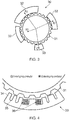
- the compensator has one or more dedicated balancing segment(s) to exert counter forces on the variable reluctance rotor of the electrical machine in such a way that the net radial force experienced by the rotor is zero or substantially reduced, as depicted as in Figure 3 , which shows schematically a transverse cross-section through an example of the electrical machine 30.
- the variable reluctance rotor 31 of the machine is surrounded by a stator formed as an annular array of three stator segments 32.
- the overall reluctance of the rotor-to-stator magnetic flux path varies with rotor position so that the stator segments are magnetically energizable to rotate the rotor.
- this energization causes the stator segments to exert respective radial forces, R1-R3, on the rotor. In combination these forces produce a radial UMF.
- the compensator of the machine has a balancing segment 33 which is magnetically energizable to produce a balancing force C on the rotor.
- C - ( R 1 + R 2 + R 3 ).
- the reluctance of the rotor-to-compensator magnetic flux path is invariant with rotor position such that the compensator does not affect the operation of the machine.
- the balancing segment 33 can take various forms.
- One option, show in Figure 4 is to adopt an asymmetrical E-core geometry for the balancing segment 33 in which the segment has a row of salient teeth 34 projecting towards the rotor.
- the teeth can have unequal tooth widths and/or unequal spacings 35.
- the segment has a centrally located and concentrated conductor winding 36. When electrical excitation is applied to the conductor winding, a magnetic field establishes in the air gap between the segment and the rotor 31 with varying magnitude depending on the local tooth width and tooth spacing.
- the unbalanced magnetic pull vector over the rotor 31 due to the stator during all possible conditions can first be estimated.
- the net magnitude and angular span of the net unbalanced magnetic pull can then be used to configure the compensator.
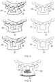
- the segment can have a U-core geometry.
- the segment can extend circumferentially to different distances either side of the winding structure.
- the segment can have a varying air gap thickness.
- the balancing segment 33 has a U-core geometry and salient teeth 34 with unequal tooth widths and unequal tooth spacings 35.
- the segment 33 has no salient teeth, but has different circumferential spans of the U-core to either side of the winding portion 37 of the U-core.
- the segment has no salient teeth, but has different air gaps 38 to either side of the winding portion 37 so that the net magnetic pull vector lies to the small air gap side of the U-core central line, i.e. although the air gap area is identical on each side, the magnetic flux density distributions differ and hence the generated magnetic pulls differ.
- Figure 6 is another schematic transverse cross-section of the U-core geometry balancing segment 33 shown at top in Figure 5 , but also includes the conductor winding 36 of the segment.
- the conductor winding 36 of the segment Advantageously, by spreading the conductors of the winding on the outer side of the winding portion 37 into a thinner layer, the space requirement of the segment can be reduced. The thinner layer also increases the cooling area for the conductors, therefore facilitating higher electrical excitations and correspondingly higher force densities.
- the converter rating for the segment is also low.
- the balancing segment or segments of the compensator can compensate unbalanced magnetic pulls in axial directions.
- Figure 7 and 8 illustrate how this can be achieved for U-core and E-core geometries.
- Figure 7 shows schematically at left a transverse cross-section and at right a perspective view of a possible U-core geometry for a balancing segment
- Figure 8 shows schematically at top left a perspective view of a possible E-core geometry for a balancing segment, at top right a perspective view of the E-core geometry without the rotor, and at bottom centre a transverse cross-section of the E-core geometry.
- the U-core geometry balancing segment 33 of Figure 7 has different axial spans of the U-core to either side of the conductor winding 36 of the segment.
- the E-core geometry balancing segment 33 of Figure 8 also has different axial spans of the E-core to either side of the conductor winding 36, but in addition has an axially extending row of salient teeth 34 with unequal tooth widths and unequal tooth spacings 35.
- Other structures e.g. different air gaps to either side of the winding portion
- combinations of structures, for the balancing segment to achieve force compensation and an invariant reluctance rotor-to-compensator magnetic flux path are possible, i.e. by analogy with the balancing segments discussed above in respect of Figures 5 and 6 .
- the compensator can also balance an unbalanced force which has both radial and axial components. This can be achieved by a subset of balancing segment(s) balancing just radial UMFs, and another subset of balancing segment(s) balancing just axial UMFs. Another option is to configure the balancing segment(s) of the compensator (e.g. by implementing appropriate combinations of radial-compensating and axial-compensating structures) so that a given segment balances both radial and axial components of a UMF.
- An advantage of the compensator includes the capability to compensate 3D unbalanced magnetic pulls with rapid responses, e.g. by using fast-acting DC current excitations. Also the compensator can provide independent operation from the stator segments 32, since its magnetic flux circulation can be confined locally, thereby avoiding interference with the stator. In addition, the compensator can be based on relatively simple structures, which promotes reliability and facilitates integration into gas turbine engines or other rotary assemblies.
- Figure 9 shows schematically at top a perspective view and at bottom a transverse cross-section of a toothed, E-core balancing segment 33 for a racially outer variable reluctance rotor 31.
- FIG. 10 Another possibility is to incorporate permanent magnets in the balancing segments to enhance the force compensation capability of the segments. This is illustrated in Figure 10 at left for a U-core balancing segment having a permanent magnet 39 at the winding portion 37 of the core, and at right for an E-core balancing segment also having a permanent magnet 39 at the winding portion 37 of the core.
- the permanent magnet can effectively reduce the required excitation current for the same magnitude of UMF compensation.
- Figure 11 shows at top a transverse cross-section and at bottom a perspective view of two adjacent E-core balancing segments 33 whose cores are merged in this way.
- the windings 36 for the two segments can have unequal turn counts and be excited with different current magnitudes to produce the required overall magnetic compensating force vector.
- the balancing segment 33 is configured to produce the equal but opposite balancing force C on the rotor to compensate the unbalanced radial force produced by the stator segments. This can be achieved by a unipolar excitation of the windings of the balancing segment with constant DC electrical current.
- stator segments 32 are turned on but are under partial loads, such as for example all three stator segments are generating at 50% of their respective nominal loads, the radial forces R1-R3 generate a net unbalanced radial force which is the same as that shown in Figure 3 in terms of direction but is at half the magnitude.
- a unipolar DC electrical current excitation can again be applied to the windings of the balancing segment 33 but at a suitably reduced magnitude of constant DC electrical current.
- a non-constant excitation current with small ripple magnitude illustrated in Figure 12 as e.g. a saw tooth current with an excitation current ripple of magnitude ⁇ l and having a phase relative position rotor positions ⁇ fall and ⁇ rise .
- an active reluctance force can be obtained, which can be combined with the unipolar excited force to form a vectorial compensating force.
- the active reluctance force can support and mitigate any transient or uneven load conditions.
- Figure 13 depicts an example of a possible control scheme for the balancing segment 33.
- a first (lower, as depicted) closed-loop controls the DC voltage by manipulating the excitation current ripple magnitude ⁇ I and its relative position with respect to ⁇ fall and ⁇ rise as the controlled variable.
- a second (upper, as depicted) closed-loop an average excitation current reference is determined from an estimate of the radial shaft force.
- An optimal controller then combines the two control-loops to issue a single coil current reference.
- An inner excitation coil current controller (which can be based on e.g. proportional-integral, hysteresis, fuzzy logic or heuristic algorithms) regulates the excitation current and hence the appropriate amount of vectorial force to compensate for any transient or uneven force.
Landscapes
- Engineering & Computer Science (AREA)
- Power Engineering (AREA)
- Mechanical Engineering (AREA)
- General Engineering & Computer Science (AREA)
- Iron Core Of Rotating Electric Machines (AREA)
Applications Claiming Priority (1)
| Application Number | Priority Date | Filing Date | Title |
|---|---|---|---|
| GBGB1714785.1A GB201714785D0 (en) | 2017-09-14 | 2017-09-14 | Segmented electrical machine |
Publications (2)
| Publication Number | Publication Date |
|---|---|
| EP3457545A1 true EP3457545A1 (de) | 2019-03-20 |
| EP3457545B1 EP3457545B1 (de) | 2021-07-21 |
Family
ID=60159532
Family Applications (1)
| Application Number | Title | Priority Date | Filing Date |
|---|---|---|---|
| EP18189093.0A Active EP3457545B1 (de) | 2017-09-14 | 2018-08-15 | Segmentierte elektrische maschine |
Country Status (3)
| Country | Link |
|---|---|
| US (1) | US10892664B2 (de) |
| EP (1) | EP3457545B1 (de) |
| GB (1) | GB201714785D0 (de) |
Cited By (2)
| Publication number | Priority date | Publication date | Assignee | Title |
|---|---|---|---|---|
| WO2025125756A1 (fr) * | 2023-12-15 | 2025-06-19 | Safran Aircraft Engines | Module de turbomachine équipé d'une machine electrique |
| FR3156825A1 (fr) * | 2023-12-15 | 2025-06-20 | Safran Aircraft Engines | Module de turbomachine équipé d’une machine electrique |
Families Citing this family (2)
| Publication number | Priority date | Publication date | Assignee | Title |
|---|---|---|---|---|
| US20210044159A1 (en) | 2019-08-06 | 2021-02-11 | Hamilton Sundstrand Corporation | Segmented and individually wound stator core for electric propulsion motor |
| SE545125C2 (en) * | 2021-08-27 | 2023-04-11 | Magstroem Ab | Concentrated-winding electrical machines with floating exciter |
Citations (4)
| Publication number | Priority date | Publication date | Assignee | Title |
|---|---|---|---|---|
| WO2006051318A1 (en) * | 2004-11-13 | 2006-05-18 | Cranfield University | Switched reluctance motor |
| GB2511353A (en) * | 2013-03-01 | 2014-09-03 | Jaguar Land Rover Ltd | Electric machine and method of operation thereof |
| EP3035504A2 (de) | 2014-12-18 | 2016-06-22 | Rolls-Royce plc | Elektrische maschinen |
| EP3261237A1 (de) * | 2016-06-21 | 2017-12-27 | Jan-Dirk Reimers | Radnabenantrieb mittels elektrischer, segmentierter ringmaschine nach dem reluktanzprinzip |
Family Cites Families (5)
| Publication number | Priority date | Publication date | Assignee | Title |
|---|---|---|---|---|
| US5365137A (en) * | 1990-11-01 | 1994-11-15 | Dynamic Systems International Inc. | Electric motor |
| US5672925A (en) * | 1992-08-06 | 1997-09-30 | Electric Power Research Institute, Inc. | Doubly salient variable reluctance machine with stationary permanent magnets or auxiliary field windings |
| US6121711A (en) | 1993-11-08 | 2000-09-19 | Mitsubishi Denki Kabushiki Kaisha | Rotary motor and production method thereof, and laminated core and production method thereof |
| GB2508022B (en) | 2012-11-20 | 2015-07-15 | Jaguar Land Rover Ltd | Electric machine and method of operation thereof |
| WO2014079881A2 (en) * | 2012-11-20 | 2014-05-30 | Jaguar Land Rover Limited | Electric machine and method of operation thereof |
-
2017
- 2017-09-14 GB GBGB1714785.1A patent/GB201714785D0/en not_active Ceased
-
2018
- 2018-08-15 EP EP18189093.0A patent/EP3457545B1/de active Active
- 2018-09-07 US US16/124,240 patent/US10892664B2/en active Active
Patent Citations (4)
| Publication number | Priority date | Publication date | Assignee | Title |
|---|---|---|---|---|
| WO2006051318A1 (en) * | 2004-11-13 | 2006-05-18 | Cranfield University | Switched reluctance motor |
| GB2511353A (en) * | 2013-03-01 | 2014-09-03 | Jaguar Land Rover Ltd | Electric machine and method of operation thereof |
| EP3035504A2 (de) | 2014-12-18 | 2016-06-22 | Rolls-Royce plc | Elektrische maschinen |
| EP3261237A1 (de) * | 2016-06-21 | 2017-12-27 | Jan-Dirk Reimers | Radnabenantrieb mittels elektrischer, segmentierter ringmaschine nach dem reluktanzprinzip |
Cited By (3)
| Publication number | Priority date | Publication date | Assignee | Title |
|---|---|---|---|---|
| WO2025125756A1 (fr) * | 2023-12-15 | 2025-06-19 | Safran Aircraft Engines | Module de turbomachine équipé d'une machine electrique |
| FR3156826A1 (fr) * | 2023-12-15 | 2025-06-20 | Safran Aircraft Engines | Module de turbomachine équipé d’une machine electrique |
| FR3156825A1 (fr) * | 2023-12-15 | 2025-06-20 | Safran Aircraft Engines | Module de turbomachine équipé d’une machine electrique |
Also Published As
| Publication number | Publication date |
|---|---|
| US20190081532A1 (en) | 2019-03-14 |
| US10892664B2 (en) | 2021-01-12 |
| GB201714785D0 (en) | 2017-11-01 |
| EP3457545B1 (de) | 2021-07-21 |
Similar Documents
| Publication | Publication Date | Title |
|---|---|---|
| US10892664B2 (en) | Segmented electrical machine | |
| US7296409B2 (en) | Electric motor assisted turbocharger | |
| US7619332B2 (en) | Permanent magnet type electric rotating machine and wind turbine electric power generation system | |
| US4503377A (en) | Variable speed rotary electric machine | |
| US6984910B2 (en) | Generator with composite rotor coil retention components | |
| US7388300B2 (en) | Starter-generator operable with multiple variable frequencies and voltages | |
| EP2355306A2 (de) | Rotierende elektrische Maschine mit Permanentmagnet | |
| US20140328668A1 (en) | Electro-magnetic coupling system | |
| EP3012438A1 (de) | Gasturbinentriebwerks- kraftstoffsystem | |
| EP1490944A1 (de) | Festhaltevorrichtung und -verfahren für die rotorwicklungen eines hochgeschwindigkeitsgenerators | |
| US20100231181A1 (en) | Novel starter-generator with improved excitation | |
| EP3410574B1 (de) | Hybridsynchronmaschine | |
| US9573539B2 (en) | Electric system architecture for more-electric engine accessories | |
| US20150102606A1 (en) | Electric generator system | |
| US7015617B2 (en) | High speed generator with rotor coil support assemblies secured to interlamination disks | |
| KR100523015B1 (ko) | 차량용 교류발전기 | |
| Powell et al. | Rotor topologies for a switched-reluctance machine for the ‘more-electric’aircraft engine | |
| AU2021430176B2 (en) | Rotating electric machine and dump truck rotating electric machine system using same | |
| CN117411362A (zh) | 用于风力涡轮机的发电机中的气隙控制 | |
| US11329535B2 (en) | Manufacturing method for a segmented stator or rotor of an electrical machine | |
| EP3490108B1 (de) | Elektrische maschine | |
| CN108886312B (zh) | 双定子旋转电机 | |
| Ganev | High performance electric generators for aerospace more electric architectures | |
| Demel et al. | Samarium Cobalt (SmCo) generator/engine integration study |
Legal Events
| Date | Code | Title | Description |
|---|---|---|---|
| PUAI | Public reference made under article 153(3) epc to a published international application that has entered the european phase |
Free format text: ORIGINAL CODE: 0009012 |
|
| STAA | Information on the status of an ep patent application or granted ep patent |
Free format text: STATUS: THE APPLICATION HAS BEEN PUBLISHED |
|
| AK | Designated contracting states |
Kind code of ref document: A1 Designated state(s): AL AT BE BG CH CY CZ DE DK EE ES FI FR GB GR HR HU IE IS IT LI LT LU LV MC MK MT NL NO PL PT RO RS SE SI SK SM TR |
|
| AX | Request for extension of the european patent |
Extension state: BA ME |
|
| STAA | Information on the status of an ep patent application or granted ep patent |
Free format text: STATUS: REQUEST FOR EXAMINATION WAS MADE |
|
| 17P | Request for examination filed |
Effective date: 20190701 |
|
| RBV | Designated contracting states (corrected) |
Designated state(s): AL AT BE BG CH CY CZ DE DK EE ES FI FR GB GR HR HU IE IS IT LI LT LU LV MC MK MT NL NO PL PT RO RS SE SI SK SM TR |
|
| RAP1 | Party data changed (applicant data changed or rights of an application transferred) |
Owner name: ROLLS-ROYCE PLC |
|
| STAA | Information on the status of an ep patent application or granted ep patent |
Free format text: STATUS: EXAMINATION IS IN PROGRESS |
|
| 17Q | First examination report despatched |
Effective date: 20210209 |
|
| GRAP | Despatch of communication of intention to grant a patent |
Free format text: ORIGINAL CODE: EPIDOSNIGR1 |
|
| STAA | Information on the status of an ep patent application or granted ep patent |
Free format text: STATUS: GRANT OF PATENT IS INTENDED |
|
| GRAS | Grant fee paid |
Free format text: ORIGINAL CODE: EPIDOSNIGR3 |
|
| GRAA | (expected) grant |
Free format text: ORIGINAL CODE: 0009210 |
|
| STAA | Information on the status of an ep patent application or granted ep patent |
Free format text: STATUS: THE PATENT HAS BEEN GRANTED |
|
| INTG | Intention to grant announced |
Effective date: 20210525 |
|
| AK | Designated contracting states |
Kind code of ref document: B1 Designated state(s): AL AT BE BG CH CY CZ DE DK EE ES FI FR GB GR HR HU IE IS IT LI LT LU LV MC MK MT NL NO PL PT RO RS SE SI SK SM TR |
|
| REG | Reference to a national code |
Ref country code: GB Ref legal event code: FG4D |
|
| REG | Reference to a national code |
Ref country code: CH Ref legal event code: EP |
|
| REG | Reference to a national code |
Ref country code: DE Ref legal event code: R096 Ref document number: 602018020317 Country of ref document: DE |
|
| REG | Reference to a national code |
Ref country code: AT Ref legal event code: REF Ref document number: 1413522 Country of ref document: AT Kind code of ref document: T Effective date: 20210815 |
|
| REG | Reference to a national code |
Ref country code: IE Ref legal event code: FG4D |
|
| REG | Reference to a national code |
Ref country code: LT Ref legal event code: MG9D |
|
| REG | Reference to a national code |
Ref country code: NL Ref legal event code: MP Effective date: 20210721 |
|
| REG | Reference to a national code |
Ref country code: AT Ref legal event code: MK05 Ref document number: 1413522 Country of ref document: AT Kind code of ref document: T Effective date: 20210721 |
|
| PG25 | Lapsed in a contracting state [announced via postgrant information from national office to epo] |
Ref country code: PT Free format text: LAPSE BECAUSE OF FAILURE TO SUBMIT A TRANSLATION OF THE DESCRIPTION OR TO PAY THE FEE WITHIN THE PRESCRIBED TIME-LIMIT Effective date: 20211122 Ref country code: NO Free format text: LAPSE BECAUSE OF FAILURE TO SUBMIT A TRANSLATION OF THE DESCRIPTION OR TO PAY THE FEE WITHIN THE PRESCRIBED TIME-LIMIT Effective date: 20211021 Ref country code: NL Free format text: LAPSE BECAUSE OF FAILURE TO SUBMIT A TRANSLATION OF THE DESCRIPTION OR TO PAY THE FEE WITHIN THE PRESCRIBED TIME-LIMIT Effective date: 20210721 Ref country code: LT Free format text: LAPSE BECAUSE OF FAILURE TO SUBMIT A TRANSLATION OF THE DESCRIPTION OR TO PAY THE FEE WITHIN THE PRESCRIBED TIME-LIMIT Effective date: 20210721 Ref country code: BG Free format text: LAPSE BECAUSE OF FAILURE TO SUBMIT A TRANSLATION OF THE DESCRIPTION OR TO PAY THE FEE WITHIN THE PRESCRIBED TIME-LIMIT Effective date: 20211021 Ref country code: AT Free format text: LAPSE BECAUSE OF FAILURE TO SUBMIT A TRANSLATION OF THE DESCRIPTION OR TO PAY THE FEE WITHIN THE PRESCRIBED TIME-LIMIT Effective date: 20210721 Ref country code: SE Free format text: LAPSE BECAUSE OF FAILURE TO SUBMIT A TRANSLATION OF THE DESCRIPTION OR TO PAY THE FEE WITHIN THE PRESCRIBED TIME-LIMIT Effective date: 20210721 Ref country code: RS Free format text: LAPSE BECAUSE OF FAILURE TO SUBMIT A TRANSLATION OF THE DESCRIPTION OR TO PAY THE FEE WITHIN THE PRESCRIBED TIME-LIMIT Effective date: 20210721 Ref country code: HR Free format text: LAPSE BECAUSE OF FAILURE TO SUBMIT A TRANSLATION OF THE DESCRIPTION OR TO PAY THE FEE WITHIN THE PRESCRIBED TIME-LIMIT Effective date: 20210721 Ref country code: FI Free format text: LAPSE BECAUSE OF FAILURE TO SUBMIT A TRANSLATION OF THE DESCRIPTION OR TO PAY THE FEE WITHIN THE PRESCRIBED TIME-LIMIT Effective date: 20210721 Ref country code: ES Free format text: LAPSE BECAUSE OF FAILURE TO SUBMIT A TRANSLATION OF THE DESCRIPTION OR TO PAY THE FEE WITHIN THE PRESCRIBED TIME-LIMIT Effective date: 20210721 |
|
| PG25 | Lapsed in a contracting state [announced via postgrant information from national office to epo] |
Ref country code: PL Free format text: LAPSE BECAUSE OF FAILURE TO SUBMIT A TRANSLATION OF THE DESCRIPTION OR TO PAY THE FEE WITHIN THE PRESCRIBED TIME-LIMIT Effective date: 20210721 Ref country code: LV Free format text: LAPSE BECAUSE OF FAILURE TO SUBMIT A TRANSLATION OF THE DESCRIPTION OR TO PAY THE FEE WITHIN THE PRESCRIBED TIME-LIMIT Effective date: 20210721 Ref country code: GR Free format text: LAPSE BECAUSE OF FAILURE TO SUBMIT A TRANSLATION OF THE DESCRIPTION OR TO PAY THE FEE WITHIN THE PRESCRIBED TIME-LIMIT Effective date: 20211022 |
|
| REG | Reference to a national code |
Ref country code: CH Ref legal event code: PL |
|
| REG | Reference to a national code |
Ref country code: DE Ref legal event code: R097 Ref document number: 602018020317 Country of ref document: DE Ref country code: BE Ref legal event code: MM Effective date: 20210831 |
|
| PG25 | Lapsed in a contracting state [announced via postgrant information from national office to epo] |
Ref country code: LI Free format text: LAPSE BECAUSE OF NON-PAYMENT OF DUE FEES Effective date: 20210831 Ref country code: DK Free format text: LAPSE BECAUSE OF FAILURE TO SUBMIT A TRANSLATION OF THE DESCRIPTION OR TO PAY THE FEE WITHIN THE PRESCRIBED TIME-LIMIT Effective date: 20210721 Ref country code: CH Free format text: LAPSE BECAUSE OF NON-PAYMENT OF DUE FEES Effective date: 20210831 |
|
| PLBE | No opposition filed within time limit |
Free format text: ORIGINAL CODE: 0009261 |
|
| STAA | Information on the status of an ep patent application or granted ep patent |
Free format text: STATUS: NO OPPOSITION FILED WITHIN TIME LIMIT |
|
| PG25 | Lapsed in a contracting state [announced via postgrant information from national office to epo] |
Ref country code: SM Free format text: LAPSE BECAUSE OF FAILURE TO SUBMIT A TRANSLATION OF THE DESCRIPTION OR TO PAY THE FEE WITHIN THE PRESCRIBED TIME-LIMIT Effective date: 20210721 Ref country code: SK Free format text: LAPSE BECAUSE OF FAILURE TO SUBMIT A TRANSLATION OF THE DESCRIPTION OR TO PAY THE FEE WITHIN THE PRESCRIBED TIME-LIMIT Effective date: 20210721 Ref country code: RO Free format text: LAPSE BECAUSE OF FAILURE TO SUBMIT A TRANSLATION OF THE DESCRIPTION OR TO PAY THE FEE WITHIN THE PRESCRIBED TIME-LIMIT Effective date: 20210721 Ref country code: MC Free format text: LAPSE BECAUSE OF FAILURE TO SUBMIT A TRANSLATION OF THE DESCRIPTION OR TO PAY THE FEE WITHIN THE PRESCRIBED TIME-LIMIT Effective date: 20210721 Ref country code: LU Free format text: LAPSE BECAUSE OF NON-PAYMENT OF DUE FEES Effective date: 20210815 Ref country code: EE Free format text: LAPSE BECAUSE OF FAILURE TO SUBMIT A TRANSLATION OF THE DESCRIPTION OR TO PAY THE FEE WITHIN THE PRESCRIBED TIME-LIMIT Effective date: 20210721 Ref country code: CZ Free format text: LAPSE BECAUSE OF FAILURE TO SUBMIT A TRANSLATION OF THE DESCRIPTION OR TO PAY THE FEE WITHIN THE PRESCRIBED TIME-LIMIT Effective date: 20210721 Ref country code: AL Free format text: LAPSE BECAUSE OF FAILURE TO SUBMIT A TRANSLATION OF THE DESCRIPTION OR TO PAY THE FEE WITHIN THE PRESCRIBED TIME-LIMIT Effective date: 20210721 |
|
| 26N | No opposition filed |
Effective date: 20220422 |
|
| PG25 | Lapsed in a contracting state [announced via postgrant information from national office to epo] |
Ref country code: IT Free format text: LAPSE BECAUSE OF FAILURE TO SUBMIT A TRANSLATION OF THE DESCRIPTION OR TO PAY THE FEE WITHIN THE PRESCRIBED TIME-LIMIT Effective date: 20210721 Ref country code: IE Free format text: LAPSE BECAUSE OF NON-PAYMENT OF DUE FEES Effective date: 20210815 Ref country code: BE Free format text: LAPSE BECAUSE OF NON-PAYMENT OF DUE FEES Effective date: 20210831 |
|
| PG25 | Lapsed in a contracting state [announced via postgrant information from national office to epo] |
Ref country code: CY Free format text: LAPSE BECAUSE OF FAILURE TO SUBMIT A TRANSLATION OF THE DESCRIPTION OR TO PAY THE FEE WITHIN THE PRESCRIBED TIME-LIMIT Effective date: 20210721 |
|
| P01 | Opt-out of the competence of the unified patent court (upc) registered |
Effective date: 20230528 |
|
| PG25 | Lapsed in a contracting state [announced via postgrant information from national office to epo] |
Ref country code: HU Free format text: LAPSE BECAUSE OF FAILURE TO SUBMIT A TRANSLATION OF THE DESCRIPTION OR TO PAY THE FEE WITHIN THE PRESCRIBED TIME-LIMIT; INVALID AB INITIO Effective date: 20180815 |
|
| PG25 | Lapsed in a contracting state [announced via postgrant information from national office to epo] |
Ref country code: MK Free format text: LAPSE BECAUSE OF FAILURE TO SUBMIT A TRANSLATION OF THE DESCRIPTION OR TO PAY THE FEE WITHIN THE PRESCRIBED TIME-LIMIT Effective date: 20210721 |
|
| PG25 | Lapsed in a contracting state [announced via postgrant information from national office to epo] |
Ref country code: MT Free format text: LAPSE BECAUSE OF FAILURE TO SUBMIT A TRANSLATION OF THE DESCRIPTION OR TO PAY THE FEE WITHIN THE PRESCRIBED TIME-LIMIT Effective date: 20210721 |
|
| PGFP | Annual fee paid to national office [announced via postgrant information from national office to epo] |
Ref country code: DE Payment date: 20250827 Year of fee payment: 8 |
|
| PGFP | Annual fee paid to national office [announced via postgrant information from national office to epo] |
Ref country code: GB Payment date: 20250826 Year of fee payment: 8 |
|
| PGFP | Annual fee paid to national office [announced via postgrant information from national office to epo] |
Ref country code: FR Payment date: 20250825 Year of fee payment: 8 |
|
| PG25 | Lapsed in a contracting state [announced via postgrant information from national office to epo] |
Ref country code: TR Free format text: LAPSE BECAUSE OF FAILURE TO SUBMIT A TRANSLATION OF THE DESCRIPTION OR TO PAY THE FEE WITHIN THE PRESCRIBED TIME-LIMIT Effective date: 20210721 |