EP3457682A1 - Kalibriervorrichtung, kalibrierverfahren, optische vorrichtung, bildgebungsvorrichtung projektionsvorrichtung, messsystem und messverfahren - Google Patents
Kalibriervorrichtung, kalibrierverfahren, optische vorrichtung, bildgebungsvorrichtung projektionsvorrichtung, messsystem und messverfahren Download PDFInfo
- Publication number
- EP3457682A1 EP3457682A1 EP17796161.2A EP17796161A EP3457682A1 EP 3457682 A1 EP3457682 A1 EP 3457682A1 EP 17796161 A EP17796161 A EP 17796161A EP 3457682 A1 EP3457682 A1 EP 3457682A1
- Authority
- EP
- European Patent Office
- Prior art keywords
- coordinates
- calibration
- camera
- dimensional
- pixel coordinates
- Prior art date
- Legal status (The legal status is an assumption and is not a legal conclusion. Google has not performed a legal analysis and makes no representation as to the accuracy of the status listed.)
- Withdrawn
Links
Images


Classifications
-
- H—ELECTRICITY
- H04—ELECTRIC COMMUNICATION TECHNIQUE
- H04N—PICTORIAL COMMUNICATION, e.g. TELEVISION
- H04N23/00—Cameras or camera modules comprising electronic image sensors; Control thereof
- H04N23/60—Control of cameras or camera modules
-
- G—PHYSICS
- G06—COMPUTING OR CALCULATING; COUNTING
- G06T—IMAGE DATA PROCESSING OR GENERATION, IN GENERAL
- G06T7/00—Image analysis
- G06T7/80—Analysis of captured images to determine intrinsic or extrinsic camera parameters, i.e. camera calibration
-
- G—PHYSICS
- G06—COMPUTING OR CALCULATING; COUNTING
- G06T—IMAGE DATA PROCESSING OR GENERATION, IN GENERAL
- G06T7/00—Image analysis
- G06T7/60—Analysis of geometric attributes
Definitions
- the present invention relates to calibration devices, calibration methods, optical devices, photographing devices, projecting devices, measurement systems, and measurement methods.
- a camera model includes a plurality of unknown parameters (camera parameters).
- camera parameters By obtaining camera parameters in advance by using a calibration device, it is possible to mathematically obtain principal rays in the real world, corresponding to two-dimensional coordinates (pixel coordinates) of an image.
- the principal rays are also called back-projected straight lines or lines of sight corresponding to pixel coordinates.
- Camera calibration is performed by the following procedure by using a mathematical camera model representing a process of capturing an image of three-dimensional coordinates in the real world with a camera and then transforming the three-dimensional coordinates into two-dimensional coordinates of an image.
- a mathematical camera model representing a process of capturing an image of three-dimensional coordinates in the real world with a camera and then transforming the three-dimensional coordinates into two-dimensional coordinates of an image.
- three-dimensional coordinates in the real world hereinafter referred to as world coordinates
- x, y, z are projected to normalized image-surface coordinates (u p , v p ) by using Eq. 1.
- a rotation matrix R and a translation vector T in Eq. 2 represent three-dimensional coordinate transformation from the world coordinates to the camera coordinates. These are values representing the position and orientation of the camera in relation to the world coordinates and are referred to as external parameters.
- Eq. 1 is based on the assumption that all principal rays intersect at the optical center of the camera. Then, (u d , v d ), which is the normalized image-surface coordinates (u p , v p ) with distortion aberration added thereto, is obtained.
- Distortion parameters are defined in various ways depending on the application.
- Eq. 3 is a model in which distortion aberrations of not higher than the third order are taken into consideration; however, models in which higher-order terms are further added, like the fifth order, the seventh order, and so forth, are also used.
- the representative distortion model among these models is the Brown model of Non-Patent Literature 2, expressed in Eq. 5.
- an image of a calibration chart with which the world coordinates (x, y, z) include a plurality of known feature points is captured by means of a camera.
- pixel coordinates (u, v) at which the feature points were captured in the image are obtained through image processing.
- Camera parameters are obtained by obtaining a plurality of measurement data representing the correspondence between world coordinates (x, y, z) and pixel coordinates (u, v) in this manner.
- an optical system involves pupil aberration, and thus all principal rays do not intersect at one point on the entrance pupil.
- Pupil aberration is particularly prominent in the case where a wide-angle lens having a large angle of view is used. Furthermore, since a wide-angle lens having a large angle of view generally involves large distortion aberrations, the higher-order terms in Eq. 5 become necessary. This results in an increase in the number of parameters in the camera model, which makes it difficult to optimize the camera model. Furthermore, since the camera model in Eq. 1 is based on perspective projection, it is not possible in principle to calibrate a wide-angle lens having a half angle of view not less than 90°.
- the present invention has been made in view of the situation described above, and it is an object thereof to provide a calibration device, a calibration method, an optical device, a photographing device, a projecting device, a measurement system, and a measurement method that make it possible to accurately obtain camera parameters of a camera having a large angle of view in a short time.
- the present invention provides the following solutions.
- One aspect of the present invention provides a calibration device for an optical device including a two-dimensional image conversion element having a plurality of pixels and including an optical system that forms an image-forming relationship between the image conversion element and a three-dimensional world coordinate space, the calibration device including a calibration-data obtaining unit that obtains calibration data representing the correspondence between two-dimensional pixel coordinates of the image conversion element and three-dimensional world coordinates of the world coordinate space; and a parameter calculating unit that fits a camera model representing the direction of a principal ray in the world coordinate space, corresponding to the pixel coordinates, as a function of the pixel coordinates on the basis of the calibration data obtained by the calibration-data obtaining unit, thereby calculating parameters of the camera model.
- the parameter calculating unit may fit the camera model representing, as a function of the pixel coordinates, two-dimensional coordinates (P( ⁇ )cos ⁇ , P( ⁇ )sin ⁇ ) obtained by transforming three-dimensional world coordinates (x, y, z) in the calibration data obtained by the calibration-data obtaining unit on the basis of three-dimensional spherical coordinates (r, ⁇ , ⁇ ) that are equal to the world coordinates.
- the parameter calculating unit may fit the camera model representing, as functions of the pixel coordinates, the direction of the principal ray and the coordinates of a point that the principal ray passes through.
- the parameter calculating unit may fit the camera model representing, as a function of the pixel coordinates, the coordinates of a point that the principal ray passes through, dictated by two-dimensional coordinates, in a plane orthogonal to the direction of the principal ray, at the intersection between the plane and the principal ray.
- the plane may pass through the center of an entrance pupil of the optical system.
- the parameter calculating unit may fit the camera model to the calibration data by alternately updating a model representing the direction of the principal ray as a function of the pixel coordinates and a model representing, as a function of the pixel coordinates, the coordinates of a point that the principal ray passes through.
- the parameter calculating unit may fit a model of a straight line, represented as a function of the pixel coordinates, to a distribution of residuals of the calibration data in relation to the camera model, and may update, on the basis of an intercept parameter in the model of the straight line, parameters of the model representing, as the function of the pixel coordinates, the coordinates of the point that the principal ray passes through.
- the parameter calculating unit may obtain data representing the direction of world coordinates in the calibration data in relation to the coordinates of the point that the principal ray passes through, obtained according to the camera model from the pixel coordinates in the calibration data, and may fit a model representing the direction of the principal ray as a function of the pixel coordinates to the data, thereby updating parameters of the model.
- the parameter calculating unit may transform three-dimensional world coordinates (x, y, z) in the calibration data obtained by the calibration-data obtaining unit into three-dimensional coordinates (rP( ⁇ )cos ⁇ , rP( ⁇ )sin ⁇ , r) on the basis of three-dimensional spherical coordinates (r, ⁇ , ⁇ ) that are equal to the world coordinates, and may then fit a camera model representing a straight line in the transformed coordinate system as a function of the pixel coordinates.
- the parameter calculating unit may fit a camera model representing the slope and the intercept of the straight line individually as two-dimensional functions of the pixel coordinates, the straight line being dictated by the slope thereof in relation to the r axis of the transformed coordinate system and the intercept thereof constituting the intersection with a plane perpendicular to the r axis.
- the function of the pixel coordinates may have the same form as a function representing an image-forming relationship between two-dimensional planes.
- the function representing the image-forming relationship between the two-dimensional planes may be represented by a linear sum of a plurality of two-dimensional vectors of the image coordinates.
- the parameter calculating unit may fit the camera model to the calibration data by using the linear least squares method.
- the parameter calculating unit may include a parameter calculating unit that sets, on the basis of parameters obtained by fitting the camera model representing the straight line in the transformed coordinates (rP( ⁇ )cos ⁇ , rP( ⁇ )sin ⁇ , r) as a function of the pixel coordinates, initial values of camera parameters of a camera model representing the direction of the principal ray and the coordinates of a point that the principal ray passes through individually as functions of the pixel coordinates, and that then iteratively optimizes the camera model, thereby calculating the parameters of the camera model.
- the parameter calculating unit may fit the camera model to calibration data obtained by transforming three-dimensional world coordinates in the calibration data obtained by the calibration-data obtaining unit into world coordinates rotated by one or more rotation angles among three rotation angles representing rotations of the world coordinates, thereby obtaining one or more rotation angles that minimize the residual of the camera model.
- the parameter calculating unit may fit the camera model to calibration data obtained by transforming three-dimensional world coordinates in the calibration data obtained by the calibration-data obtaining unit into world coordinates translated by one or more components among three translation components representing translations of the world coordinates, thereby obtaining one or more translation components that minimize the residual of the camera model.
- the optical device may include a plurality of image conversion elements and an optical system that forms an image-forming relationship between the image conversion elements and a three-dimensional world coordinate space
- the calibration-data obtaining unit may obtain the calibration data of the individual image conversion elements and the optical system
- the parameter calculating unit may fit the camera models represented as functions of two-dimensional pixel coordinates of the individual image conversion elements to the calibration data of the individual image conversion elements and the optical system.
- the optical device may be a photographing device
- the image conversion element may be an image-capturing element
- the optical system may be an image-capturing optical system
- the optical device may be a projecting device
- the image conversion element may be an image-forming element
- the optical system may be a projection optical system
- another aspect of the present invention provides an optical device having installed therein the camera model in which the parameters calculated by one of the calibration devices described above.
- the camera model may be saved as discrete data representing the correspondence between a plurality of pixel coordinates and world coordinates on two planes or curved surfaces.
- the camera model may be saved as discrete data representing the correspondence between a plurality of pixel coordinates and the directions and intercepts of principal rays in the world coordinate space.
- the optical device may include a principal-ray calculating unit that obtains a principal ray in the world coordinate space, corresponding to the pixel coordinates, from two coordinate values of the pixel coordinates according to the camera model.
- the optical device may include a world-coordinate calculating unit that obtains three coordinate values of world coordinates as an intersection between the principal ray in the world coordinate space, corresponding to the pixel coordinates and obtained according to the camera model, and a plane or curved surface given in the three-dimensional world coordinate space.
- the optical device may include a distortion-corrected-image generating unit that obtains, according to the camera model, the world coordinates corresponding to pixel coordinates of an image acquired or formed by the image conversion element, thereby generating an image in which distortion has been corrected.
- another aspect of the present invention provides an optical device having installed therein a camera model in which the rotation angles obtained by the calibration device described above are set as camera parameters.
- another aspect of the present invention provides an optical device having installed therein a camera model in which the translation components obtained by the calibration device described above are set as camera parameters.
- the optical device may include a coordinate transformation unit that mutually transforms camera coordinates and world coordinates on the basis of the rotation angles and the translation components.
- another aspect of the present invention provides a photographing device constituted of one of the optical devices described above.
- another aspect of the present invention provides a projecting device constituted of one of the optical devices described above.
- another aspect of the present invention provides a measurement system including the calibration device described above; one or more photographing devices; and a three-dimensional-coordinate calculation processing unit that calculates three-dimensional coordinates of a point of interest of an object from pixel coordinates of images acquired by the photographing devices from a plurality of viewpoints, wherein the three-dimensional-coordinate calculation processing unit uses the camera model used in the calibration device, the parameters of the camera models of the photographing devices, calculated by the calibration device, and rotation angles and/or translation components of the photographing devices.
- Another aspect of the present invention provides a measurement system including the calibration device described above; one or more photographing devices; one or more projecting devices; and a three-dimensional-coordinate calculation processing unit that calculates three-dimensional coordinates of a point of interest of an object onto which structured light from the projecting devices is projected, from pixel coordinates of images of the object captured by the photographing devices, wherein the three-dimensional-coordinate calculation processing unit uses the camera model used in the calibration device, the parameters of the camera models of the photographing devices, calculated by the calibration device, rotation angles and/or translation components of the photographing devices, the parameters of the camera models of the projecting devices, calculated by the calibration device, and rotation angles and/or translation components of the projecting devices.
- another aspect of the present invention provides a calibration method including a step of obtaining calibration data for an optical device including a two-dimensional image conversion element having a plurality of pixels and including an optical system that forms an image-forming relationship between the image conversion element and a three-dimensional world coordinate space, the calibration data representing the correspondence between two-dimensional pixel coordinates of the image conversion element and three-dimensional world coordinates of the world coordinate space; and a step of fitting, on the basis of the obtained calibration data, a camera model representing, as a function of the pixel coordinates, the direction of a principal ray in the world coordinate space, corresponding to the pixel coordinates, thereby calculating parameters of the camera model.
- another aspect of the present invention provides a measurement method including a step of obtaining calibration data for a photographing device including a two-dimensional image conversion element having a plurality of pixels and including an optical system that forms an image-forming relationship between the image conversion element and a three-dimensional world coordinate space, the calibration data representing the correspondence between two-dimensional pixel coordinates of the image conversion element and three-dimensional world coordinates of the world coordinate space; a step of fitting, on the basis of the obtained calibration data, a camera model representing, as a function of the pixel coordinates, the direction of a principal ray in the world coordinate space, corresponding to the pixel coordinates, thereby calculating parameters of the camera model; and a step of calculating three-dimensional coordinates of a point of interest of an object from pixel coordinates of images from a plurality of viewpoints by using the calculated parameters, the camera model used to calculate the parameters, and rotation angles and/or translation components of the photographing device.
- Another aspect of the present invention provides a measurement method including a step of obtaining calibration data for a photographing device and a projecting device each including a two-dimensional image conversion element having a plurality of pixels and including an optical system that forms an image-forming relationship between the image conversion element and a three-dimensional world coordinate space, the calibration data representing the correspondence between two-dimensional pixel coordinates of the image conversion element and three-dimensional world coordinates of the world coordinate space; a step of fitting, on the basis of the obtained calibration data, a camera model representing, as a function of the pixel coordinates, the direction of a principal ray in the world coordinate space, corresponding to the pixel coordinates, thereby calculating parameters of the camera model; and a step of calculating three-dimensional coordinates of a point of interest of an object from pixel coordinates of images from pixel coordinates from a plurality of viewpoints in images, captured by the photographing device, of the object onto which structured light from the projecting device is projected, by using the calculated parameters, the camera model used to calculate the parameters,
- an advantage is afforded in that it is possible to accurately obtain camera parameters of a camera having a large angle of view in a short time.
- the calibration device is a camera calibration device 1 for calibrating a camera (photographing device or optical device) 2 that transfers captured images to the outside as image files in a predetermined format.
- the camera 2 is used as an example of an optical device in this embodiment.
- the camera calibration device 1 includes a base 3 to which the camera 2 to be calibrated is secured; a z-axis moving stage 4 provided on the base 3; a calibration chart 6 fixed to a movable part 5 that is moved by the z-axis moving stage 4; and a computer 7 connected to the camera 2 and the z-axis moving stage 4.
- the three-dimensional coordinate axes of the camera calibration device 1 are defined as shown in Fig. 1 .
- the base 3 to which the camera 2 is secured, the calibration chart 6, and the z-axis moving stage 4 constitute a calibration-data acquisition unit 8.
- the z-axis moving stage 4 is a linear driving mechanism that is driven by a motor 4a to linearly move the movable part 5.
- the moving direction of the movable part 5 is defined as the z axis
- the horizontal direction and the vertical direction in a plane perpendicular to the z axis are defined as the x axis and the y axis.
- the position of the coordinate origin is defined in the vicinity of the entrance pupil of a camera lens 9.
- the camera 2 is attached to the base 3 such that the optical axis thereof is parallel to the z axis, such that the horizontal direction and the vertical direction of the imaging surface thereof are parallel to the x axis and the y axis, respectively, and such that the coordinate origin coincides with a predetermined position of the camera 2.
- the calibration chart 6 is a chessboard 10 in Fig. 2 , which is widely used for camera calibration.
- the calibration chart 6 is fixed to the movable part 5 so as to squarely face the camera 2 secured to the base 3, i.e., so as to be disposed in a plane perpendicular to the z axis.
- the calibration chart 6 may be any kind of chart including a plurality of feature points.
- the calibration chart 6 is configured so as to be movable to arbitrary points in the z-axis direction by the z-axis moving stage 4.
- the computer 7 works to control imaging by the camera 2 so as to read captured images as image files in a predetermined format. Furthermore, the computer 7 works to control the z-axis moving stage 4 so as to move the calibration chart 6 to a certain position in the z-axis direction. Furthermore, the computer 7 also works as a parameter calculating unit that calculates camera parameters by fitting a camera model to acquired configuration data.
- the chessboard 10 is a flat plate-shaped member having a checkerboard pattern in which black and white squares are arrayed on a plane so as to form a square lattice, and the intersections corresponding to the vertices of the individual squares are utilized as feature points for camera calibration (the feature points will hereinafter be referred to as lattice points 11).
- chessboard 10 As the chessboard 10, a chessboard with which a number of lattice points 11 sufficient for camera calibration fall within the imaging range of the camera 2 is used.
- the imaged range of the chessboard 10 varies depending on the object distance, preferably, at least about 10 ⁇ 10 lattice points 11 should be imaged at each object distance.
- a reference position mark 12 is provided in the vicinity of the center of the calibration chart 6 in order to define correspondence between the pixel coordinates of the imaged lattice points 11 and the world coordinates of the lattice points 11 on the calibration chart 6.
- the chessboard 10 is installed on the camera calibration device 1 such that the lattice point nearest to the lower right side of the reference position mark 12 (a center lattice point 13) is located on the z axis and such that the vertical and horizontal directions of the chessboard 10 become parallel to the x axis and the y axis, respectively.
- the world coordinates (x, y, z) of the individual lattice points 11 and 13 are fixed as known values from the lattice pitch of the square lattice of the chessboard 10 and the moved position of the z-axis moving stage 4.
- a camera calibration method performed by using the thus-configured camera calibration device 1 according to this embodiment will be described.
- an operator first attaches the camera 2 to be calibrated to the camera calibration device 1 in accordance with the definitions of the coordinate axes, thereby connecting the camera 2 to the computer 7. Then, a measurement program inside the computer 7 is started.
- the z-axis moving stage 4 is moved so as to locate the calibration chart 6 at the end, closer to the camera 2, of the object distance range for calibrating the camera 2 (step S1). Then, an image of the calibration chart 6 is captured by the camera 2, and the resulting image file is transferred to the computer 7 (step S2). Furthermore, these steps S1 and S2 are repeated until imaging is performed a predetermined number of times (step S3). As the predetermined number of times, for example, a number of times greater than or equal to five times is set.
- step S1 for each iteration, the movable part 5 is moved by the z-axis moving stage 4 such that the object distance from the camera 2 to the calibration chart 6 increases by a predetermined interval.
- the amounts of movement of the movable part 5 need not be equal intervals, but the calibration chart 6 should preferably be imaged at about five or more points with different object distances within the object distance range for calibrating the camera 2.
- the procedure proceeds to the next step S4.
- the plurality of image files transferred to the computer 7 in steps S1 to S3 are subjected to image processing to obtain the pixel coordinates of the individual lattice points 11 within the imaging range, and the pixel coordinates of the center of gravity of the reference position mark 12 in the individual image files are obtained (step S4).
- the method of obtaining the pixel coordinates of the lattice points 11 on the chessboard 10 by using subpixels is known, and thus a description thereof is omitted here.
- the pixel coordinates of the individual lattice points 11, obtained in step S4, are associated with the world coordinates of the lattice points 11 on the calibration chart 6 (step S5). Since the center lattice point 13, which is nearest to the lower right side of the reference position mark 12, is located on the z axis of the world coordinates, as described earlier, it is possible to associate the pixel coordinates of the individual lattice points 11 and 13 with world coordinates with reference to the center lattice point 13. Lastly, all the pixel coordinates and world coordinates that have been associated are written to a measurement data file, whereby the measurement is finished. Through the procedure described above, measurement data needed for the optimization of camera parameters is obtained.
- Fig. 4A is a sectional view of the camera 2, which serves to explain object-side principal rays associated with the pixel coordinates of the camera 2.
- the camera 2 includes an imaging optical system (optical system) 14 and an imaging element (image conversion element) 18.
- the camera coordinates (x c , y c , zc) are defined as shown in Fig. 4A .
- the origin of the camera coordinates is the center 404 of the entrance pupil of the imaging optical system 14, and the z c axis coincides with the optical axis 403.
- a u axis and a v axis of pixel coordinates are defined for the imaging surface of the imaging element 18, parallel to the horizontal direction and the vertical direction of the imaging element 18, respectively.
- the u axis and the v axis are respectively parallel to the x c axis and the y c axis of the camera coordinates.
- the world coordinates and the camera coordinates substantially coincide with each other.
- Fig. 4A depicts object-side principal rays 19 that are incident on the centers of the individual pixels of the imaging element 18 through the imaging optical system 14.
- the principal rays 19 refer to rays that pass through the center of the aperture stop (not shown) of the imaging optical system 14.
- a blurred image on the imaging element 18, corresponding to an object point on a principal ray 19 spreads around the intersection between that principal ray 19 and the imaging element 18, so that the position of the image point is unchanged if the center of gravity of the light intensities at the blurred image points is considered as the image position. Therefore, all the object points on an object-side principal ray 19 form an image at a single image point. That is, the object-side principal ray 19 is a back-projected straight line of the image point.
- the relationship between the direction of a principal ray 19 and the image point corresponding thereto is expressed by a projection formula.
- the entrance pupil is a virtual aperture generated by forming an image of the aperture stop by means of an optical system located on the object side thereof.
- the group of object-side principal rays passes through the vicinity of the center 404 of the entrance pupil, but does not intersect the entrance pupil at the single point located at the center 404.
- a camera model according to the present invention which is created so as to be suitable for such a situation, will be described.
- a model of the directions of the primary rays will be described with reference to Fig. 4B .
- this embodiment will be described in the context of, as an example, the imaging element 18 in which the pixels are arrayed to form a square lattice, this embodiment is not limited to this example.
- camera coordinates (r, ⁇ , ⁇ ) represented by spherical coordinates are newly introduced.
- the polar angle ⁇ thereof is equal to the angle made by a principal ray 19 and the optical axis 403, i.e., is equal to the angle of view.
- the azimuth ⁇ is an angle representing the direction about the optical axis 403.
- the relationship between the orthogonal coordinates and camera coordinates (x c , y c , z c ) is expressed by Eq. 7.
- x c y c z c r ⁇ sin ⁇ ⁇ ⁇ cos ⁇ ⁇ r ⁇ sin ⁇ ⁇ ⁇ sin ⁇ r ⁇ sin ⁇ ⁇
- the directions of principal rays associated with the individual pixels on the imaging element 18 are plotted on a P( ⁇ )cos ⁇ -P( ⁇ )sin ⁇ plane 411, the directions are arrayed to form a square lattice similar to the pixel array.
- the directions of the principal rays are displaced to directions 413 different from the directions of the square lattice 412.
- the displacement from the designed directions 412 to the actual directions 413 are considered as a phenomenon similar to distortion of the image position due to distortion aberration. That is, in this embodiment, on the basis of the Brown model in Eq. 5, a model of the direction ( ⁇ , ⁇ ) of a principal ray associated with a pixel coordinate (u, v) on the imaging element 18 is created as in Eq. 8.
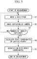
- an x 0 '-y 0 ' plane 406 obtained by rotating the x c -y c plane perpendicular to the z c axis and passing through the center 404 of the entrance pupil so as to be perpendicular to a principal ray 19 of interest will be considered.
- the intersection 407 between the principal ray 19 and the plane 406 is defined as "the intercept of the principal ray".
- the intercepts of all the principal rays are located at the origin 422.
- the pupil aberration increases as the angle of view becomes greater, and thus the intercept distribution 423 constitutes a distribution like pincushion distortion.
- the intercept distribution 423 is considered as a phenomenon similar to the distortion of an image position due to distortion aberration. That is, in this embodiment, a model of the coordinates (x 0 ', y 0 ') of an intercept on the plane 421 is created as in Eq. 9, similarly to Eq. 8.
- the individual coefficients of the intercept are denoted with primes attached thereto.
- x 0 ′ y 0 ′ k 0 ′ u v + k 1 ′ ⁇ 2 u v + p 1 ′ ⁇ 2 + 2 u 2 2 ⁇ uv + p 2 ′ 2 ⁇ uv ⁇ 2 + 2 v 2 + ⁇ ⁇ u ′ ⁇ ⁇ v ′
- the camera model according to the present invention i.e., the linear equation of a principal ray is expressed as in Eq. 10.
- x c y c z c R s x 0 ′ y 0 ′ 0 + ⁇ l m n
- (l, m, n) denotes a direction cosine representing the principal ray direction and has the relationship in Eq. 11 with ( ⁇ , ⁇ ) in Eq. 8.
- l m n sin ⁇ ⁇ ⁇ cos ⁇ ⁇ sin ⁇ ⁇ ⁇ sin ⁇ ⁇ cos ⁇ ⁇
- Rs denotes a three-dimensional rotation matrix for rotating the z c axis in the direction of (l, m, n), and ⁇ denotes a parameter of a straight line. Since Rs also depends on the pixel coordinates (u, v), Eq. 11 represents a non-linear model. A method in which the non-linear model is transformed into a linear model for the purpose of computation will be described with reference to Figs. 5A and 5B .
- Fig. 5A is a sectional view of the imaging optical system 14 and the imaging element 18 of the camera 2 as well as the camera coordinates (x c , y c , z c ), similarly to Fig. 4A .
- the camera coordinate space in Fig. 5A is transformed into a projected coordinate space ( ⁇ , ⁇ , r) in Fig. 5B . That is, an object point (x c , y c , z c ) on a spherical surface 511 of radius r in Fig. 5A is transformed via the spherical coordinates (r, ⁇ , ⁇ ) in Eq. 7 onto a plane 521 in Fig. 5B by using Eq. 12.
- ⁇ ⁇ r ⁇ P ⁇ cos ⁇ ⁇ sin ⁇ ⁇
- spherical surfaces 512 and 513 in Fig. 5A are respectively transformed to planes 522 and 523 in Fig. 5B .
- the entire space centered around the center 404 of the entrance pupil in Fig. 5A is transformed into the interior of a cone surrounded by broken lines 524 in Fig. 5B .
- a principal ray 19 in the camera coordinates corresponds to a straight line 535 in the projected coordinate space ( ⁇ , ⁇ , r).
- ⁇ ⁇ a c r + b d
- the straight line 525 in Eq. 13 becomes a curved line instead of a straight line when inversely transformed into the original camera coordinates in Fig. 5A .
- the slope (a, c) coincides with the model of the principal ray direction in Eq. 8. Therefore, the principal ray 19 in Fig. 5A constitutes an asymptote to the curved line obtained by inverse transformation into the camera coordinates, and it is possible to obtain the direction thereof from the slope (a, c) in Eq. 13.
- Rz denotes Eq. 15, which represents a rotation matrix about the origin of the x 0 '-y 0 ' plane.
- R z cos ⁇ ⁇ ⁇ sin ⁇ ⁇ sin ⁇ ⁇ cos ⁇ ⁇
- M denotes Eq. 16, which is a matrix representing magnification by projection.
- M m ⁇ 0 0 m ⁇
- m ⁇ d P ⁇ d ⁇
- m ⁇ P ⁇ sin ⁇
- a straight line 526 parallel to the straight line 525 and passing through the coordinate origin will be considered.
- transforming the straight line 514 according to Eq. 12 yields a straight line that coincides with the straight line 526.
- the surface corresponding to the cylindrical surface in Fig. 5A and including the straight line 525 in Fig. 5B constitutes an elliptic cylinder centered about the straight line 526.
- Eq. 17 is used as a model of the straight line 525 in the ( ⁇ , ⁇ , r) coordinate space.
- ⁇ ⁇ k 0 r + k 0 " u v + k 1 r + k 1 " ⁇ 2 u v + p 1 r + p 1 " ⁇ 2 ⁇ 2 + 2 u 2 2 ⁇ uv + p 2 r + p 2 " 2 ⁇ uv ⁇ 2 + 2 v 2 + ⁇ ⁇ ur + ⁇ ⁇ u " ⁇ ⁇ vr + ⁇ ⁇ v "
- tildes are attached to parameters that are not sufficiently optimized.
- the components of a perpendicular line drawn from camera coordinates (x c , y c , z c ) of measurement data to the straight-line model of a principal ray constitute residuals ( ⁇ x , ⁇ y , ⁇ z ).
- both sides of Eq. 18 are inversely rotated by using the rotation matrix Rs to obtain Eq. 19 (primes are added to the camera coordinates and residuals after the inverse rotation).
- x c ′ y c ′ z c ′ x ⁇ 0 ′ y ⁇ 0 ′ 0 + ⁇ 0 0 1 + ⁇ c ′ ⁇ y ′ 0
- x c ′ y c ′ z c ′ R ⁇ s ⁇ 1 x c y c z c
- ⁇ x ′ ⁇ y ′ 0 R ⁇ s ⁇ 1 ⁇ x ⁇ y ⁇ z
- the residuals attributable to the unsuitable parameter constitute a straight line group having slopes ( ⁇ l', ⁇ m') and intercepts ( ⁇ x 0 ', ⁇ y 0 ') in the ( ⁇ x ', ⁇ y ', ⁇ ) space. Therefore, it is possible to update the individual coefficients in the intercept model in Eq. 9 by adding the individual coefficients (k0", k1", p1", p2", ⁇ u", ⁇ v") of the intercepts obtained by fitting the straight-line group model in Eq. 21 to these residuals, Eq. 21 being generated by substituting ( ⁇ x ', ⁇ y ', ⁇ ) for ( ⁇ , ⁇ , r) in Eq.
- the direction model in Eq. 8 is updated on the basis of the intercept model in the updated Eq. 9. That is, the direction cosine (l, m, n) in Eq. 10 is obtained from the camera coordinates (x c , y c , z c ) of measurement data and the updated intercept.
- the direction cosine (l, m, n) is transformed into the form on the left-hand side of Eq. 8 by using Eqs. 11 and 6, and the direction model in Eq. 8 is fitted to the result to update the individual coefficients therein.
- the principal-ray direction model in Eq. 8 and the intercept model in Eq. 9 are optimized alternately by repeating the procedure described above. This makes it possible to obtain the suitable principal-ray model in Eq. 10.
- the camera models used in the camera calibration device 1 are models of an object-side principal ray corresponding to pixel coordinates. These models are constructed on the basis of the linear model in Eq. 5 representing the image-forming relationship, involving distortion aberration, between object coordinates and pixel coordinates.
- the model of the coordinate system obtained by transformation using the projection formula in Eq. 17 has a feature that it has a form wherein, on the basis of the linear model in Eq. 5 representing the image-forming relationship involving distortion, the individual coefficients therein are replaced with first-order equations of the distance r.
- another feature of the camera model in Eq. 17 used in the camera calibration device 1 according to this embodiment is that it represents a projected object coordinate vector ( ⁇ , ⁇ ) by using the linear sum of linearly independent two-dimensional basis function vectors constituted of variables (u, v, r). Since the linear sum of basis function vectors is used, the coefficients of the models representing ⁇ and ⁇ coordinates are in common. Thus, it is possible to obtain the coefficients of the individual basis function vectors from all the measurement data by using the linear least squares method.
- step S602 measurement data representing correspondence between world coordinates (x, y, z) and pixel coordinates (u, v) is obtained (step S602). Then, by using Eqs. 7 and 12, the world coordinates (x, y, z) are transformed into projected coordinates ( ⁇ , ⁇ , r) (step S603). Then, the camera model expressed in Eq.
- step S604 is fitted to all the pixel coordinates (u, v) of measurement data and the projected coordinates ( ⁇ , ⁇ , r) by using the linear least squares method to obtain the individual coefficients (camera parameters) of the camera model in Eq. 17 (step S604).
- the coefficients (k 0 , k 1 , p 1 , p 2 , ⁇ u, ⁇ v) in Eq. 8 and the coefficients (k 0 ', k 1 ', p 1 ', p 2 ', ⁇ u', ⁇ v') in Eq. 9 are initialized respectively with the obtained coefficients (k 0 , k 1 , p 1 , p 2 , ⁇ u, ⁇ v) and (k 0 ", k 1 ", p 1 ", p 2 ", ⁇ u", ⁇ v") in Eq. 17 (step S605). Note that the effect M of magnification by the projection in Eq.
- step S606 the distance between the principal ray in Eq. 10 and the world coordinates (x, y, z) corresponding to pixel coordinates (u, v) is calculated for all the measurement data, and the sum of squares of the calculated distances is obtained (step S606).
- the camera calibration is finished.
- step S608 is the following procedure.
- the individual coefficients of the camera model are obtained as described above, and then the camera calibration in this embodiment is finished.
- the camera model in which the camera parameters obtained in this embodiment are set can be used as follows in a photographing device including the camera 2 having the camera model installed therein.
- the photographing device further includes a straight-line calculating unit (principal-ray calculating unit: not shown) that calculates a straight line corresponding to pixel coordinates in the world coordinate space; a world-coordinate calculating unit (not shown) that calculates three-dimensional world coordinates; and a distortion-corrected-image generating unit (not shown) that generates an image in which distortion is corrected.
- a straight-line calculating unit principal-ray calculating unit: not shown
- a world-coordinate calculating unit not shown
- a distortion-corrected-image generating unit not shown
- the straight-line calculating unit assigns pixel coordinates (u, v) of interest in Eqs. 8 and 9, thereby obtaining the direction ( ⁇ , ⁇ ) and intercept (x 0 ', y 0 ') of the principal ray. Furthermore, an equation of the principal ray is obtained as in Eq. 10.
- the world-coordinate calculating unit calculates the intersection between the principal ray expressed by the abovementioned equation and the predetermined plane or curved surface, thereby obtaining the target world coordinates (x, y, z).
- the distortion-corrected-image generating unit it is possible to correct distortion in an image captured by the calibrated camera 2.
- a method for this purpose will be described.
- the image becomes distorted.
- the world-coordinate calculating unit calculates the intersection between the principal ray for pixel coordinates (u, v) and the plane with the object distance z, thereby projecting the pixel coordinates (u, v) to world coordinates (x, y).
- a distortion-corrected image is a procedure involving assigning the pixel values of the original image corresponding to the pixel coordinates (integers) of the distortion-corrected image to the pixel coordinates after distortion correction. This procedure will be described with reference to a flowchart in Fig. 7 .
- first pixel coordinates (u c , v c ) after distortion correction are determined (step S11).
- initial values (0, 0) are assigned to pixel coordinates (u, v) before distortion correction (step S12). If it is possible in some way to estimate the pixel coordinates (u, v) before distortion correction, corresponding to the pixel coordinates (u c , v c ) after distortion correction, the pixel coordinates (u, v) before distortion correction may be used as initial values.
- step S13 The intersection between the principal ray for the pixel coordinates (u, v) before distortion correction and the plane with the reference object distance z is calculated to obtain world coordinates (x, y) (step S13). Then, the obtained world coordinates (x, y) are normalized by the lateral magnification k 0 z to obtain pixel coordinates (u', v') (step S14).
- step S15 The distance between the obtained pixel coordinates (u', v') and the pixel coordinates (u c , v c ) after distortion correction is obtained (step S15).
- the procedure proceeds to step S18. Otherwise, through the updating of the pixel coordinates (u, v) before distortion correction (step S17), the procedure returns to step S13 (step S16).
- the pixel coordinates (u, v) before distortion correction when the iterative optimization has converged corresponds to the pixel coordinates (u c , v c ) after distortion correction via the camera model in Eq. 10.
- the pixel coordinates (u, v) are generally non-integers.
- the pixel values of the pixel coordinates (u, v) are obtained by bilinear interpolation from the pixel values of four pixels neighboring the pixel coordinates. Then, the obtained pixel values are used as the pixel values of the pixel coordinates (u c , v c ) after distortion correction (step S18).
- other methods, such as bicubic interpolation may be adopted for the interpolation of pixel values.
- the above steps S11 to S18 are repeated for all the pixel coordinates (u c , v c ) after distortion correction (step S19), and then the distortion correction is finished.
- a plane with the object distance z is used as a reference.
- an image captured with the camera 2 designed with the intent of equidistant projection does not necessarily become an accurate equidistant projection image due to manufacturing errors, etc. of the camera 2.
- world coordinates corresponding to pixel coordinates are calculated each time by using the camera model in Eq. 10.
- the camera model in Eq. 10 By calculating those world coordinates in advance and saving the world coordinates in the form of a data array, it is possible to increase the computation speed.
- the directions and intercepts of principal rays corresponding to the individual pixel coordinates are calculated in advance individually in the form of data arrays.
- the intersections between two planes or curved surfaces such as spherical surfaces of the world coordinates and principal rays corresponding to the individual pixel coordinates may be calculated in advance in the form of data arrays, and the principal ray for the pixel of interest may be obtained by interpolating these data arrays.
- camera calibration is performed on the basis of measurement data of lattice points 11 and 13 arrayed to form a square lattice on the planar chessboard 10.
- the feature points on the calibration chart 6 may be patterns other than the lattice points 11 and 13.
- measurement data may be created by capturing an image of dot marks distributed in a plane and using the position of the center of gravity thereof as pixel coordinates.
- the feature points used for camera calibration in the present invention need not be arrayed regularly in the world coordinate space. Even if the layout of the feature points is random, as long as it is possible to know the correspondence between the world coordinates and the pixel coordinates by way of measurement, simulation, or the like, it is possible to fit the camera model according to the present invention to the feature points.
- the only condition required for measurement data for the camera calibration in this embodiment is that the correspondence between the world coordinates and the pixel coordinates is known.
- calibration charts 6 may be installed at a plurality of angles of view so as to encompass all the angles of view of the camera. Also in this case, it is possible to fit the camera calibration method of this embodiment if the correspondence between the world coordinates of the feature points on the calibration charts 6 and the pixel coordinates is known.
- the camera parameters of the camera model of the camera coordinates in Eq. 10 are subjected to iterative optimization, while using, as initial values, camera parameters obtained by fitting the camera model of the projected coordinate space in Eq. 17.
- either one of these in the procedure may be omitted.
- the camera calibration device 1 and the camera calibration method according to this embodiment it is possible to create an accurate model of the pupil aberration of the imaging optical system 14 by using the camera model according to this embodiment. Furthermore, it is also possible to create models of rotationally asymmetric distortion aberration and pupil aberration. This makes it possible to accurately represent the group of principle rays, which serves to improve the accuracy of the camera model.
- the camera model based on the projection formula of the camera 2 to be calibrated is used in the camera calibration device 1 and the camera calibration method according to this embodiment, it is possible to moderate the highest order required in the model. At the same time, as opposed to the existing art, it is also possible to calibrate cameras with half angles of view not less than 90°.
- the feature points used in the camera calibration device 1 and the camera calibration method according to this embodiment need not be arrayed regularly. Therefore, as long as it is possible to clarify the correspondence between the world coordinates and the pixel coordinates, it becomes possible to choose an arbitrary acquisition method based on measurement or calculation suitable for the camera 2 to be calibrated.
- the camera calibration method described as the first embodiment is directed to the case where the entrance pupil of the camera 2 to be calibrated substantially coincides with the origin of the world coordinates, the optical axis is parallel to the z axis of the camera calibration device 1, and the horizontal direction and the vertical direction of the image-capturing surface are parallel to the x axis and the y axe, respectively, as shown in Fig. 1 .
- the camera calibration method described as this embodiment is directed to the case where this condition is not satisfied, i.e., the world coordinates do not coincide with the camera coordinates.
- the camera model used in the first embodiment is based on camera coordinates having the origin at the center 404 of the entrance pupil of the image-capturing optical system 14 of the camera 2 to be calibrated. Therefore, the abovementioned camera model is fittable when the world coordinates of the lattice points 11 on the calibration chart 6 in the camera calibration device 1 in Fig. 1 are transformed into camera coordinates.
- the transformation from the world coordinates (x, y, z) to the camera coordinates (x c , y c , z c ) is expressed in Eq. 22 by using the three-axis rotation matrix R and the translation vector T in Eq. 2.
- x c y c z c r 11 r 12 r 13 r 21 r 22 r 23 r 31 r 32 r 33 x y z + t x t y t z
- the three-axis rotation angles ⁇ x , ⁇ y , and ⁇ z of the rotation matrix R and the three components (t x , t y , t z ) of the translation vector T are optimized so as to minimize the residual thereof.
- the residual of the camera model is minimized when the world coordinates transformed by using Eq. 22 coincide with the camera coordinates.
- step S802 measurement data representing the correspondence between the world coordinates (x, y, z) and the pixel coordinates (u, v) is obtained (step S802).
- step S803 the rotation angles ⁇ x , ⁇ y , and ⁇ z and the translation components t x , t y , and t z included in Eq. 22 are initialized (step S803). Zero may be used as these initial values. Alternatively, if it is possible to estimate the rotation angles and translation of the camera 2 in some way, those values may be used as the initial values.
- the world coordinates (x, y, z) of the measurement data are transformed into camera coordinates (x c , y c , z c ) by using Eq. 22 (step S804).
- the camera coordinates (x c , y c , z c ) are transformed into projected coordinates ( ⁇ , ⁇ , r) by using Eqs. 7 and 12 (step S805).
- the camera model in Eq. 17 is fitted to all the pixel coordinates (u, v) in the measurement data and the projected coordinates ( ⁇ , ⁇ , r) by using the linear least squares method (step S806).
- step S809 When the standard deviation of the resulting residuals is less than a predetermined value, the procedure proceeds to step S809. Otherwise, through the updating of the rotation angles ⁇ x , ⁇ y , and ⁇ z and the translation components t x , t y , and t z (step S808), the procedure returns to step S804 (step S807).
- This iterative optimization is executed by using an ordinary optimization algorithm, such as the downhill simplex method.
- the rotation angles ⁇ x , ⁇ y , and ⁇ z and the translation components t x , t y , and t z with which the residual serving as an evaluation function is converged to the minimal value represent the optimal rotation angles and translation.
- step S811 the distance between the principal ray in Eq. 10 and the camera coordinates (x c , y c , z c ), corresponding to pixel coordinates (u, v), is calculated for all the measurement data, and the sum of squares of the calculated distances is obtained (step S811).
- the camera calibration is finished.
- This iterative optimization is executed by using the downhill simplex method or the alternate optimization algorithm described earlier.
- the optimal rotation angles ⁇ x , ⁇ y , and ⁇ z and translation components t x , t y , and t z are obtained as described above, the camera calibration is finished.
- the camera model in which the camera parameters obtained by using the camera calibration method according to this embodiment are set in a photographing device including the camera 2 having the camera model installed therein.
- the principal ray obtained from pixel coordinates of interest by using Eq. 10 is an equation at camera coordinates (x c , y c , z c ).
- a coordinate transformation unit (not shown) that transforms camera coordinates (x c , y c , z c ) into world coordinates (x, y, z) is included in a photographing device including the camera 2.
- camera coordinates (x c1 , y c1 ) and (x c2 , y c2 ) corresponding to pixel coordinates are obtained with two certain object distances z c1 and z c2 in the camera coordinates. As described in the context of the first embodiment, these camera coordinates are obtained as the intersections between the principal ray expressed in Eq. 10 and planes having the object distances z c1 and z c2 .
- the coordinate transformation unit transforms these two sets of camera coordinates (x c1 , y c1 , z c1 ) and (x c2 , y c2 , z c2 ) into world coordinates (x 1 , y 1 , z 1 ) and (x 2 , y 2 , z 2 ) by way of the inverse transformation in Eq. 22 using the optimal rotation angles ⁇ x , ⁇ y , and ⁇ z and translation components t x , t y , and t z .
- the straight line passing through the two points obtained by the transformation is the principal ray in the world coordinates.
- the three rotation angles ⁇ x , ⁇ y , and ⁇ z and the three translation components t x , t y , and t z are optimized.
- those values may be fixed to the known values and excluded from the parameters to be optimized. In this case, it suffices to optimize only the remaining unknown parameter or parameters. This results in a reduction in the number of parameters to be optimized, which serves to reduce the calculation time.
- the camera parameters of the camera model of the camera coordinates in Eq. 10 are subjected to iterative optimization, while using, as initial values, camera parameters obtained by fitting the camera model of the projected coordinate space in Eq. 17.
- either one of these in the procedure may be omitted.
- the following describes the procedure in which the initialization of the camera parameters with the camera model of the projected coordinate space in Eq. 17 is omitted in this embodiment.
- the world coordinates (x, y, z) in the measurement data are transformed into camera coordinates (x c , y c , z c ) by using Eq. 22.
- the rotation angles ⁇ x , ⁇ y , and ⁇ z and the translation components t x , t y , and t z included in the abovementioned Eq. 22 and the coefficients in Eqs. 8 and 9 are iteratively optimized so as to minimize the sum of squares of the distances between the principal rays in Eq. 10 corresponding to the pixel coordinates (u, v) in the measurement data and the abovementioned camera coordinates (x c , y c , z c ).
- the camera calibration method it is possible to obtain a highly accurate camera model even in the case where the position and orientation of the camera 2 are not properly aligned in relation to the world coordinates. Furthermore, even in the case where a large number of camera parameters are required, such as distortion aberration, since the iterative optimization is executed by being divided into the procedure for optimizing three or fewer rotation angles and three or fewer translation components and the procedure for optimizing only the individual coefficients in the equation for a principal ray, the optimization of the camera model does not fail, and it is possible to considerably reduce the calculation time.
- the camera calibration device 32 is applied to calibration of a multi-viewpoint camera 33, 34, 35 directed to shape restoration.
- a multi-viewpoint camera 33, 34, 35 directed to shape restoration.
- the three cameras (photographing devices or optical devices) 33, 34, and 35 to be calibrated are secured to a camera securing table 36 with a layout matching the usage conditions of the multi-viewpoint camera. Then, the camera securing table 36 is attached to the camera calibration device 32 so that the individual cameras 33, 34, and 35 can capture images of the calibration chart 6.
- the configuration of the other parts, including the calibration chart 6, the z-axis moving stage 4, and the computer 7, is the same as that in Fig. 1 , and thus a description thereof will be omitted.
- the camera calibration device 32 operates in the same manner as the camera calibration device 1 according to the first embodiment.
- images of the calibration chart 6 at a plurality of object distances are automatically captured by the cameras 33, 34, and 35, and the pixel coordinates of the lattice points 11 of the calibration chart 6 are obtained from the images.
- steps S2, S4, and S5 in the flowchart in Fig. 3 are executed for each of the three cameras 33, 34, and 35.
- the camera models of the individual cameras 33, 34, and 35 are obtained from the abovementioned measurement data of the individual cameras 33, 34, and 35.
- the procedure for this purpose is the same as that in the second embodiment.
- the individual camera models in which the camera parameters obtained by the camera calibration device 32 according to this embodiment are set in a photographing device including the cameras 33, 34, and 35 having the individual camera models installed therein.
- the procedure of the coordinate transformation unit described in the context of the second embodiment, should be applied.
- the measurement program in the flowchart in Fig. 3 may be executed individually and sequentially for the individual cameras.
- the position where the z-axis moving stage 4 is set on the camera calibration device 32 may be changed such that the calibration chart 6 squarely faces each of the cameras subject to measurement.
- This camera calibration method is effective in the case where there is a camera that cannot capture an image of the calibration chart 6 that is secured in one direction because the multi-viewpoint camera 33, 34, and 35 are disposed so as to surround the observation area.
- the camera calibration device 32 and the camera calibration method according to this embodiment it is possible to calibrate the multi-viewpoint camera 33, 34, and 35 in a layout matching the usage conditions. Furthermore, an advantage is afforded in that it is possible to handle world coordinates or principal rays corresponding to the pixel coordinates of the individual cameras 33, 34, and 35 in a single common world coordinate system.
- the measurement system includes the camera calibration device 32 according to the third embodiment, the multi-viewpoint camera 33, 34, and 35, and a three-dimensional coordinate calculation processing unit (the computer 7).
- Camera calibration is executed by the camera calibration device 32 to obtain camera models in which the individual camera parameters for the multi-viewpoint camera 33, 34, and 35 are set.
- the three-dimensional calculation processing unit included in the computer 7 calculates the world coordinates of a point of interest on the surface of an object photographed by the multi-viewpoint camera 33, 34, and 35.
- the procedure for this purpose is shown in Fig. 11 .
- an algorithm for evaluating the degree of similarity in the distribution of image luminance values such as block matching
- the method of calculating the degree of similarity it is possible to use one of a plurality of calculation methods depending on the requirements of the calculation speed and calculation precision, such as the square sum of differences (SSD), the sum of absolute differences (SAD), normalized cross correlation (NCC), and zero-mean normalized cross correlation.
- SSD square sum of differences
- SAD sum of absolute differences
- NCC normalized cross correlation
- ZNCC is desirable considering the robustness against the differences in brightness among the images individually captured by the cameras 33, 34, and 35.
- step S105 the simultaneous equations are solved by first using the equation of the x and z components of the principal ray, and y is obtained by using the obtained value of z.
- the principal ray of the image I34 used to designate a pixel is used.
- step S108 an effect of further reducing the error in the world coordinates to be obtained by using the world coordinates of the midpoint of the two world coordinates A and B.
- world coordinates are calculated for pixels designated by the user in the image I34 in the description of each step, world coordinates may be automatically calculated for a plurality of pixels determined as being characteristic as a result of feature-point extraction processing executed on the image I34, or world coordinates may be calculated for all the pixels in the image I34 in the case where there are only small restrictions on calculation resources.
- the calibration device according to this embodiment is a projector calibration device 37.
- the calibration device internally includes an image forming element (image conversion element: not shown), such as a liquid crystal element, and a projection optical system (optical system: not shown), constituting a device for calibrating a projector (projection device) 38 that projects the formed image to the outside.
- the projector 38 is used as an example of an optical device.
- the projector calibration device 37 includes a base 39 to which the projector 38 to be calibrated is secured; a z-axis moving stage 4 provided on the base 39; a calibration chart 6 fixed to a movable part 5 of the z-axis moving stage 4; and a camera 2 that is disposed at a position adjacent to the projector 38 and that captures an image of the calibration chart 6.
- the camera 2 and the projector 38 are attached to the projector calibration device 37 such that the optical axes of these devices become parallel to the z axis of the projector calibration device 37 and such that a predetermined position of the projector 38 coincides with the coordinate origin.
- the imaging range of the camera 2 should preferably encompass the image projection range of the projector 38.
- the configuration of the other parts, such as the calibration chart 6, the z-axis moving stage 4, and the computer 7, is the same as that in Fig. 1 .
- the calibration chart 6 used in this embodiment it is possible to replace the chessboard 10 in Fig. 2 and a plain screen with each other.
- the computer 7 also has a function for controlling the projector 38 so as to cause the projector 38 to project a predetermined image.
- the camera 2 is calibrated in the state where the chessboard 10 in Fig. 2 is installed as the calibration chart 6.
- the procedure for this purpose is the same as that in the first or second embodiment.
- the calibration chart 6 is replaced with the plain screen.
- the pattern of the chessboard 10 in Fig. 2 is projected from the projector 38 onto the calibration chart 6 through the projection optical system.
- the pixel coordinates of the individual lattice points 11 and 13 on the chessboard 10 are known in the pixel coordinates defined on the image-forming element (not shown) inside the projector 38.
- the world coordinates (x, y) of the lattice points 11 of the chessboard 10 projected onto the calibration chart 6 are obtained by using the camera model of the camera 2 calibrated by using the procedure described earlier.
- measurement data representing the correspondence between the pixel coordinates (u, v) and the world coordinates (x, y, z) of the projector 38 is obtained.
- the method of obtaining the camera parameters of the projector 38 from the measurement data is the same as that in the first or second embodiment.
- the pattern that is projected by the projector 38 is not limited to the pattern of the chessboard 10. It is also possible to adopt a pattern, such as dot marks, that makes it possible to calculate the pixel coordinates of feature points from images captured by the camera 2. Alternatively, a method in which discrete pixels of the projector 38 are individually turned on may be employed.
- the world coordinates (x, y) of the feature points projected by the projector 38 are measured by the camera 2 calibrated in advance. This measurement is also possible by using a method in which the image-capturing element 18 is installed instead of the calibration chart 6 and in which images of the projected pattern are directly captured. Furthermore, other acquisition methods may be chosen as long as it is possible to clarify the correspondence between world coordinates and pixel coordinates. As described above, with the projector calibration device 37 according to this embodiment, it is possible to calibrate the projector 38 by using a camera model.
- the measurement system includes the projector calibration device 37 according to the fourth embodiment, the projector 38, and a three-dimensional coordinate calculation processing unit (the computer 7).
- a camera model in which the camera parameters of the projector 38 are set is obtained.
- a camera model in which the camera parameters of the camera 2 are set is obtained.
- a random-dot pattern image I38 is used as the pattern that is projected by the projector 38.
- the measurement method is shown in Fig. 12 .
- step S113 the simultaneous equations are solved by first using the equation of the x and z components of the principal ray, and y is obtained by using the obtained value of z.
- the principal ray of I2 used to designate a pixel is used.
- the projector 38 projects one kind of pseudo-random pattern as a pattern.
- the method used may be a phase shift method in which a plurality of object images onto which a plurality of stripes having varied phases are projected with time differences are used or a spatial coding method in which a plurality of images onto which binary patterns having a plurality of resolutions are projected are used.
- a plurality of projectors 38 may be provided for a single camera 2, or a plurality of projectors 38 may be provided for a plurality of cameras 2.
- three-dimensional coordinates may be automatically calculated for a plurality of pixels determined as being characteristic as a result of feature-point extraction processing executed on the image I2, or three-dimensional coordinates may be calculated for all the pixels in the image I2 in the case where there are only small restrictions about calculation resources.
- the camera calibration methods described in the context of the first to fourth embodiments are methods for the case where the pupil aberration of the camera 2 to be calibrated is not negligible.
- the camera calibration method described in the context of this embodiment is a method for the case where the pupil aberration is negligible.
- the pupil aberration of the camera 2 being negligible is equivalent to all the principal rays intersecting the entrance pupil at the single point at the center 404 thereof. Therefore, it is possible to calibrate the camera 2 just with the principal-ray direction model in Eq. 8. That is, when the camera coordinates (x c , y c , z c ) of the lattice points 11 are transformed into projected coordinates ( ⁇ ', ⁇ ') in Eq. 23 via the spherical coordinates (r, ⁇ , ⁇ ) in Eq. 7, the camera model in Eq. 24 holds.
- measurement data representing the correspondence between the world coordinates (x, y, z) and the pixel coordinates (u, v) is obtained. Then, the world coordinates (x, y, z) of the measurement data are transformed into camera coordinates (x c , y c , z c ) by using Eq. 22. Furthermore, the camera coordinates (x c , y c , z c ) are transformed into projected coordinates ( ⁇ ', ⁇ ') by using Eqs. 7 and 23.
- the camera model in Eq. 24 is fitted to all the pixel coordinates (u, v) of the measurement data and the projected coordinates ( ⁇ ', ⁇ ') by using the linear least squares method.
- the rotation angles ⁇ x , ⁇ y , and ⁇ z and the translation components t x , t y , and t z included in Eq. 22 mentioned earlier are iteratively optimized.
- the initial values of the rotation angles ⁇ x , ⁇ y , and ⁇ z and the translation components t x , t y , and t z serving as the optimization parameters may be zero.
- the estimated values may be used as the initial values.
- This iterative optimization is executed by using an ordinary optimization algorithm, such as the downhill simplex method.
- the rotation angles ⁇ x , ⁇ y , and ⁇ z and the translation components t x , t y , and t z at the time when the evaluation function is converged to the minimal value are the optimal rotation angles and translation, and the individual coefficients of the camera model in Eq. 24 at that time are the camera parameters. Then, the camera calibration is finished.
- the camera model in which the camera parameters obtained by using the camera calibration method according to this embodiment are set in a photographing device including the camera 2 having the camera model installed therein or in the projector 38.
- the camera calibration method it is possible to reduce the number of camera parameters in the case where it is possible to disregard the pupil aberration with the camera 2 or the projector 38 to be calibrated. Furthermore, since the number of iterative optimization parameters is limited to three or fewer rotation angles and three or fewer translation components even in the case where a large number of camera parameters, such as distortion aberration, are required, the optimization of the camera model does not fail, and it is possible to considerably reduce the calculation time.
- the camera 2 or the projector 38 is not limited to a refractive optical system. It would be obvious that it is also possible to apply the present invention to a catadioptric optical system if transformation such as the inversion of the coordinate system due to reflection is taken into consideration.
- a plurality of camera calibrations individually corresponding to setting changes of the focus, zoom, diaphragm, etc. of the camera 2 or the projector 38 may be executed. Furthermore, a camera model corresponding to an arbitrary setting may be obtained by interpolating those camera models.
- camera calibration may be executed under a plurality of wavelengths of a light source.
- camera models for individual wavelengths may be used for a camera that captures images of individual wavelengths.
- image-capturing element 18 or an image-forming element is used as an example of an image conversion element in the optical devices 2, 33, 34, 35, and 38 described in the context of the first to fifth embodiments of the present invention, any image conversion element that performs mutual conversion between images and video signals may be adopted, without limitation to the imaging element 18 or an image-forming element.
Landscapes
- Engineering & Computer Science (AREA)
- Physics & Mathematics (AREA)
- Computer Vision & Pattern Recognition (AREA)
- General Physics & Mathematics (AREA)
- Theoretical Computer Science (AREA)
- Geometry (AREA)
- Multimedia (AREA)
- Signal Processing (AREA)
- Studio Devices (AREA)
- Length Measuring Devices By Optical Means (AREA)
- Image Analysis (AREA)
Applications Claiming Priority (2)
| Application Number | Priority Date | Filing Date | Title |
|---|---|---|---|
| JP2016097370 | 2016-05-13 | ||
| PCT/JP2017/017613 WO2017195801A1 (ja) | 2016-05-13 | 2017-05-10 | 較正装置、較正方法、光学装置、撮影装置、投影装置、計測システムおよび計測方法 |
Publications (1)
| Publication Number | Publication Date |
|---|---|
| EP3457682A1 true EP3457682A1 (de) | 2019-03-20 |
Family
ID=60267237
Family Applications (1)
| Application Number | Title | Priority Date | Filing Date |
|---|---|---|---|
| EP17796161.2A Withdrawn EP3457682A1 (de) | 2016-05-13 | 2017-05-10 | Kalibriervorrichtung, kalibrierverfahren, optische vorrichtung, bildgebungsvorrichtung projektionsvorrichtung, messsystem und messverfahren |
Country Status (4)
| Country | Link |
|---|---|
| US (1) | US10699440B2 (de) |
| EP (1) | EP3457682A1 (de) |
| JP (1) | JP6675478B2 (de) |
| WO (1) | WO2017195801A1 (de) |
Cited By (2)
| Publication number | Priority date | Publication date | Assignee | Title |
|---|---|---|---|---|
| CN113554710A (zh) * | 2020-04-24 | 2021-10-26 | 西门子(深圳)磁共振有限公司 | 医学影像系统中3d相机的标定方法、系统和存储介质 |
| EP4177840A1 (de) * | 2021-11-04 | 2023-05-10 | Bundesdruckerei GmbH | Verfahren zur kalibrierung einer kamera |
Families Citing this family (29)
| Publication number | Priority date | Publication date | Assignee | Title |
|---|---|---|---|---|
| CN110447220B (zh) * | 2017-03-21 | 2021-03-09 | 奥林巴斯株式会社 | 校准装置、校准方法、光学装置、摄影装置以及投影装置 |
| US11039121B2 (en) * | 2017-06-20 | 2021-06-15 | Sony Interactive Entertainment Inc. | Calibration apparatus, chart for calibration, chart pattern generation apparatus, and calibration method |
| CN110345875B (zh) * | 2018-04-04 | 2021-04-27 | 灵动科技(北京)有限公司 | 标定及测距方法、装置、电子设备及计算机可读存储介质 |
| CN110969664B (zh) * | 2018-09-30 | 2023-10-24 | 北京魔门塔科技有限公司 | 一种相机外部参数的动态标定方法 |
| US10549928B1 (en) | 2019-02-22 | 2020-02-04 | Dexterity, Inc. | Robotic multi-item type palletizing and depalletizing |
| US11741566B2 (en) | 2019-02-22 | 2023-08-29 | Dexterity, Inc. | Multicamera image processing |
| CN110232716A (zh) * | 2019-05-31 | 2019-09-13 | 深圳市道通智能航空技术有限公司 | 一种相机标定方法、装置和电子设备 |
| CN110246191B (zh) * | 2019-06-13 | 2021-03-16 | 易思维(杭州)科技有限公司 | 相机非参数模型标定方法及标定精度评估方法 |
| CN110728717B (zh) | 2019-09-27 | 2022-07-15 | Oppo广东移动通信有限公司 | 定位方法及装置、设备、存储介质 |
| CN111127559B (zh) * | 2019-12-26 | 2023-06-16 | 深圳市瑞立视多媒体科技有限公司 | 光学动捕系统中标定杆检测方法、装置、设备和存储介质 |
| EP3855397B1 (de) * | 2020-01-24 | 2021-12-29 | Axis AB | Bildgebungssystem |
| US11536655B1 (en) | 2020-02-18 | 2022-12-27 | Path AI, Inc. | Imaging systems with angled sensors and related methods |
| WO2021238923A1 (zh) * | 2020-05-25 | 2021-12-02 | 追觅创新科技(苏州)有限公司 | 相机参数标定方法及装置 |
| CN111612853B (zh) * | 2020-05-25 | 2023-08-08 | 追觅创新科技(苏州)有限公司 | 相机参数标定方法及装置 |
| JP6976537B1 (ja) * | 2020-10-08 | 2021-12-08 | 株式会社Fronteo | 情報検索装置、情報検索方法および情報検索用プログラム |
| CN112629499B (zh) * | 2020-12-03 | 2023-01-17 | 合肥中科君达视界技术股份有限公司 | 基于线扫描仪的手眼标定重复定位精度测量方法及装置 |
| CN112465918B (zh) * | 2020-12-06 | 2024-04-02 | 西安交通大学 | 一种基于Tsai标定的显微视觉标定方法 |
| CN113160322A (zh) * | 2021-03-17 | 2021-07-23 | 地平线(上海)人工智能技术有限公司 | 摄像装置标定方法和设备、介质以及电子设备 |
| CN113240752B (zh) * | 2021-05-21 | 2024-03-22 | 中科创达软件股份有限公司 | 一种内参和外参协同标定方法和装置 |
| CN115482286B (zh) * | 2021-05-31 | 2025-09-26 | 北京字跳网络技术有限公司 | 相机内参的标定验证方法、装置、设备及介质 |
| CN114199124B (zh) * | 2021-11-09 | 2023-07-25 | 汕头大学 | 基于线性拟合的坐标标定方法、装置、系统及介质 |
| CN114095657B (zh) * | 2021-11-22 | 2024-02-27 | 成都天翼空间科技有限公司 | 一种基于新增摄像头的自动校准的方法与系统 |
| CN114964035B (zh) * | 2022-04-08 | 2025-03-18 | 中国科学院上海光学精密机械研究所 | 基于空变球模型自适应单目偏折的工件面形重构方法 |
| CN115100026B (zh) * | 2022-06-15 | 2023-07-14 | 佳都科技集团股份有限公司 | 基于目标对象的标签坐标转换方法、装置、设备及存储介质 |
| CN115546318B (zh) * | 2022-11-23 | 2023-04-07 | 中科星图测控技术股份有限公司 | 一种自动高速弹道标定方法 |
| CN116429258A (zh) * | 2023-03-27 | 2023-07-14 | 苏州大学 | 场积分快照式成像光谱仪标定过程中的光斑排序方法和系统 |
| CN117387487B (zh) * | 2023-10-13 | 2025-06-20 | 哈尔滨工业大学 | 一种利用自由放置单圆柱目标的结构光标定方法 |
| US20250299366A1 (en) * | 2024-03-22 | 2025-09-25 | Deere & Company | Calibration system and method for furrow vision system |
| CN119991519B (zh) * | 2025-01-20 | 2025-09-26 | 深圳大学 | 基于光线模型的成像畸变校正方法、装置、设备及介质 |
Family Cites Families (11)
| Publication number | Priority date | Publication date | Assignee | Title |
|---|---|---|---|---|
| JP3402138B2 (ja) | 1996-09-27 | 2003-04-28 | 株式会社日立製作所 | 液晶表示装置 |
| JP2002202122A (ja) * | 2001-01-05 | 2002-07-19 | Olympus Optical Co Ltd | 2次元距離画像センサのキャリブレーション方法 |
| JP3735344B2 (ja) | 2002-12-27 | 2006-01-18 | オリンパス株式会社 | キャリブレーション装置、キャリブレーション方法、及びキャリブレーション用プログラム |
| US8121433B2 (en) * | 2008-01-18 | 2012-02-21 | California Institute Of Technology | Ortho-rectification, coregistration, and subpixel correlation of optical satellite and aerial images |
| JP2011101265A (ja) | 2009-11-06 | 2011-05-19 | Nippon Seiki Co Ltd | 較正情報算出方法、較正情報算出装置、及び広角画像処理装置 |
| CN103562963A (zh) | 2011-05-25 | 2014-02-05 | 三维Ip有限责任公司 | 用于角切片真3d显示器的对准、校准和渲染的系统和方法 |
| US20140085409A1 (en) | 2012-09-25 | 2014-03-27 | GM Global Technology Operations LLC | Wide fov camera image calibration and de-warping |
| CN105981074B (zh) * | 2014-11-04 | 2018-02-02 | 深圳市大疆创新科技有限公司 | 用于标定成像装置的系统、方法和装置 |
| WO2016076400A1 (ja) | 2014-11-13 | 2016-05-19 | オリンパス株式会社 | 較正装置、較正方法、光学装置、撮影装置、投影装置、計測システムおよび計測方法 |
| EP3182371B1 (de) * | 2015-12-17 | 2018-09-26 | Stmicroelectronics Sa | Schwellenwertbestimmung in zum beispiel einem ransac-algorithmus |
| US9784576B2 (en) * | 2015-12-28 | 2017-10-10 | Automotive Research & Test Center | Calibration method for merging object coordinates and calibration board device using the same |
-
2017
- 2017-05-10 EP EP17796161.2A patent/EP3457682A1/de not_active Withdrawn
- 2017-05-10 JP JP2018517046A patent/JP6675478B2/ja active Active
- 2017-05-10 WO PCT/JP2017/017613 patent/WO2017195801A1/ja not_active Ceased
-
2018
- 2018-11-07 US US16/183,027 patent/US10699440B2/en active Active
Cited By (2)
| Publication number | Priority date | Publication date | Assignee | Title |
|---|---|---|---|---|
| CN113554710A (zh) * | 2020-04-24 | 2021-10-26 | 西门子(深圳)磁共振有限公司 | 医学影像系统中3d相机的标定方法、系统和存储介质 |
| EP4177840A1 (de) * | 2021-11-04 | 2023-05-10 | Bundesdruckerei GmbH | Verfahren zur kalibrierung einer kamera |
Also Published As
| Publication number | Publication date |
|---|---|
| JPWO2017195801A1 (ja) | 2019-03-07 |
| US10699440B2 (en) | 2020-06-30 |
| US20190073795A1 (en) | 2019-03-07 |
| WO2017195801A1 (ja) | 2017-11-16 |
| JP6675478B2 (ja) | 2020-04-01 |
Similar Documents
| Publication | Publication Date | Title |
|---|---|---|
| US10699440B2 (en) | Calibration device, calibration method, optical device, photographing device, projecting device, measurement system, and measurement method | |
| US10798353B2 (en) | Calibration apparatus, calibration method, optical apparatus, image capturing apparatus, and projection apparatus | |
| CN107003109B (zh) | 校准装置、校准方法、光学装置、摄影装置、投影装置、测量系统以及测量方法 | |
| JP6664000B2 (ja) | 較正装置、較正方法、光学装置、撮影装置、および投影装置 | |
| JP6079333B2 (ja) | 校正装置、方法及びプログラム | |
| JP6967715B2 (ja) | カメラ校正方法、カメラ校正プログラム及びカメラ校正装置 | |
| Micusik et al. | Estimation of omnidirectional camera model from epipolar geometry | |
| CN107492127B (zh) | 光场相机参数标定方法、装置、存储介质和计算机设备 | |
| CN108489395A (zh) | 视觉测量系统结构参数标定和仿射坐标系构建方法与系统 | |
| CN113841384B (zh) | 校准装置,用于校准的图表和校准方法 | |
| US9600863B2 (en) | Method for combining images | |
| Sun et al. | Review of calibration methods for Scheimpflug camera | |
| JP2005167484A (ja) | 画像構成装置及び画像構成方法 | |
| CN106643669A (zh) | 一种多镜头多探测器航空相机单中心投影转换方法 | |
| WO2013005265A1 (ja) | 三次元座標計測装置及び三次元座標計測方法 | |
| US7133570B1 (en) | Calibrated sensor and method for calibrating same | |
| Hou et al. | Camera lens distortion evaluation and correction technique based on a colour CCD moiré method | |
| Legarda et al. | A new method for Scheimpflug camera calibration | |
| Kumar et al. | Generalized pupil-centric imaging and analytical calibration for a non-frontal camera | |
| JP2018017568A (ja) | 距離測定装置、撮像装置、および距離測定方法 | |
| CN112903103A (zh) | 基于dmd和互补全通的计算光谱成像系统及方法 | |
| Seegräber et al. | A Calibration Tool for Refractive Underwater Vision | |
| Bushnevskiy et al. | Multimode camera calibration | |
| Feng et al. | A general model and calibration method for spherical stereoscopic vision | |
| Rosebrock et al. | Complete generic camera calibration and modeling using spline surfaces |
Legal Events
| Date | Code | Title | Description |
|---|---|---|---|
| STAA | Information on the status of an ep patent application or granted ep patent |
Free format text: STATUS: THE INTERNATIONAL PUBLICATION HAS BEEN MADE |
|
| PUAI | Public reference made under article 153(3) epc to a published international application that has entered the european phase |
Free format text: ORIGINAL CODE: 0009012 |
|
| STAA | Information on the status of an ep patent application or granted ep patent |
Free format text: STATUS: REQUEST FOR EXAMINATION WAS MADE |
|
| 17P | Request for examination filed |
Effective date: 20181211 |
|
| AK | Designated contracting states |
Kind code of ref document: A1 Designated state(s): AL AT BE BG CH CY CZ DE DK EE ES FI FR GB GR HR HU IE IS IT LI LT LU LV MC MK MT NL NO PL PT RO RS SE SI SK SM TR |
|
| AX | Request for extension of the european patent |
Extension state: BA ME |
|
| STAA | Information on the status of an ep patent application or granted ep patent |
Free format text: STATUS: THE APPLICATION HAS BEEN WITHDRAWN |
|
| 18W | Application withdrawn |
Effective date: 20190614 |