EP3458123B1 - Dynamische katheterspitzenokklusion - Google Patents
Dynamische katheterspitzenokklusion Download PDFInfo
- Publication number
- EP3458123B1 EP3458123B1 EP17798884.7A EP17798884A EP3458123B1 EP 3458123 B1 EP3458123 B1 EP 3458123B1 EP 17798884 A EP17798884 A EP 17798884A EP 3458123 B1 EP3458123 B1 EP 3458123B1
- Authority
- EP
- European Patent Office
- Prior art keywords
- suction
- inflatable
- collapsible membrane
- membrane portion
- distal
- Prior art date
- Legal status (The legal status is an assumption and is not a legal conclusion. Google has not performed a legal analysis and makes no representation as to the accuracy of the status listed.)
- Active
Links
Images



Classifications
-
- A—HUMAN NECESSITIES
- A61—MEDICAL OR VETERINARY SCIENCE; HYGIENE
- A61M—DEVICES FOR INTRODUCING MEDIA INTO, OR ONTO, THE BODY; DEVICES FOR TRANSDUCING BODY MEDIA OR FOR TAKING MEDIA FROM THE BODY; DEVICES FOR PRODUCING OR ENDING SLEEP OR STUPOR
- A61M16/00—Devices for influencing the respiratory system of patients by gas treatment, e.g. ventilators; Tracheal tubes
- A61M16/04—Tracheal tubes
- A61M16/0434—Cuffs
-
- A—HUMAN NECESSITIES
- A61—MEDICAL OR VETERINARY SCIENCE; HYGIENE
- A61M—DEVICES FOR INTRODUCING MEDIA INTO, OR ONTO, THE BODY; DEVICES FOR TRANSDUCING BODY MEDIA OR FOR TAKING MEDIA FROM THE BODY; DEVICES FOR PRODUCING OR ENDING SLEEP OR STUPOR
- A61M16/00—Devices for influencing the respiratory system of patients by gas treatment, e.g. ventilators; Tracheal tubes
- A61M16/04—Tracheal tubes
- A61M16/0463—Tracheal tubes combined with suction tubes, catheters or the like; Outside connections
-
- A—HUMAN NECESSITIES
- A61—MEDICAL OR VETERINARY SCIENCE; HYGIENE
- A61M—DEVICES FOR INTRODUCING MEDIA INTO, OR ONTO, THE BODY; DEVICES FOR TRANSDUCING BODY MEDIA OR FOR TAKING MEDIA FROM THE BODY; DEVICES FOR PRODUCING OR ENDING SLEEP OR STUPOR
- A61M16/00—Devices for influencing the respiratory system of patients by gas treatment, e.g. ventilators; Tracheal tubes
- A61M16/04—Tracheal tubes
- A61M16/0475—Tracheal tubes having openings in the tube
- A61M16/0477—Tracheal tubes having openings in the tube with incorporated means for delivering or removing fluids
- A61M16/0479—Tracheal tubes having openings in the tube with incorporated means for delivering or removing fluids above the cuff, e.g. giving access to the upper trachea
-
- A—HUMAN NECESSITIES
- A61—MEDICAL OR VETERINARY SCIENCE; HYGIENE
- A61M—DEVICES FOR INTRODUCING MEDIA INTO, OR ONTO, THE BODY; DEVICES FOR TRANSDUCING BODY MEDIA OR FOR TAKING MEDIA FROM THE BODY; DEVICES FOR PRODUCING OR ENDING SLEEP OR STUPOR
- A61M16/00—Devices for influencing the respiratory system of patients by gas treatment, e.g. ventilators; Tracheal tubes
- A61M16/04—Tracheal tubes
- A61M16/0488—Mouthpieces; Means for guiding, securing or introducing the tubes
-
- A—HUMAN NECESSITIES
- A61—MEDICAL OR VETERINARY SCIENCE; HYGIENE
- A61M—DEVICES FOR INTRODUCING MEDIA INTO, OR ONTO, THE BODY; DEVICES FOR TRANSDUCING BODY MEDIA OR FOR TAKING MEDIA FROM THE BODY; DEVICES FOR PRODUCING OR ENDING SLEEP OR STUPOR
- A61M16/00—Devices for influencing the respiratory system of patients by gas treatment, e.g. ventilators; Tracheal tubes
- A61M16/20—Valves specially adapted to medical respiratory devices
Definitions
- the present invention relates generally to medical suction catheter devices, and specifically to catheter devices for aspiration of tracheobronchial secretions and/or cleaning of tracheal ventilation tubes.
- Suction catheters are commonly used to aspirate tracheobronchial fluids in patients ventilated with endotracheal tube (ETT) and tracheostomy tube devices.
- ETT endotracheal tube
- a problematic aspect of the use of suction catheters is the presence of bacterial biofilm within the ETT lumen through which the suction catheter passes. Consequently, as the suction catheter is inserted, there is high risk of it carrying bacterial biofilm from the ETT lumen deeper into the bronchial tree where the suction catheter reaches, and thereby increasing the risk of lung infection.
- buildup of substantial biofilm thickness reduces the effective free lumen of the ETT for air passage. Therefore, there is a need for maintaining cleaner ETT lumens between suction operations, and preventing buildup of significant biofilm thickness.
- a cleaning catheter that includes fluid-delivery and suction lumens.
- a flow regulator defines suction and fluid ports.
- a mechanical user control element is configured to mechanically and non-electrically set activation states of the flow regulator, and transition between first and third configurations via a second configuration.
- the flow regulator blocks fluid communication (a) between the suction port and the suction lumen and (b) between the fluid port and the fluid-delivery lumen.
- the control element When the control element is in the second configuration, the flow regulator effects fluid communication between the suction port and the suction lumen, and blocks fluid communication between the fluid port and the fluid-delivery lumen.
- the control element When the control element is in the third configuration, the flow regulator effects fluid communication (a) between the suction port and the suction lumen and (b) between the fluid port and the fluid-delivery lumen.
- the catheter body is shaped so as to define distal-most suction orifice, at a distal end of a distal portion of the cleaning catheter, distal to the inflatable element; a suction lumen; and one or more fluid-delivery lumens, which provide fluid communication between an inflation inlet and at least one inflation port which is in fluid communication with an inflatable chamber of the inflatable element.
- the suction lumen is arranged along the catheter body, and includes a proximal longitudinal portion, which is coupleable in fluid communication with a suction source.
- the distal-most suction orifice is in fluid communication with a distal portion of the suction lumen, and enables the cleaning system to selectively apply suction to the trachea.
- An outer lateral wall of the catheter body is shaped so as to define a lateral opening therethrough into the suction lumen.
- the cleaning catheter further comprises an inner membrane, which is at least partially positioned within an interior of the inflatable element and is mounted to the catheter body around the lateral opening along an air-tight seal perimeter that surrounds the lateral opening, so as to define a collapsible membrane portion that covers the lateral opening.
- the collapsible membrane portion defines the inflatable chamber between the inflatable-element outer wall and the collapsible membrane portion.
- the seal perimeter defines a straight distance between two points on the seal perimeter that are most distant from each other.
- the inner membrane is arranged such that:
- the collapsible membrane portion does not need to stretch much or at all in order to come into contact with the inner surface of the suction lumen in order to at least partially occlude the suction lumen.
- occlusion of the suction lumen is not very sensitive to the inflation pressure. For example, providing only 0.2 atm inflation gauge pressure may be sufficient to cause the collapsible membrane portion to come into contact with the inner surface of the suction lumen in order to at least partially occlude the suction lumen.
- apparatus for use with a suction source including a cleaning catheter, which includes:
- a circumferential portion of the inner membrane snugly touches a circumferential portion of the outer lateral wall of the catheter body, which circumferential portion does not define the lateral opening.
- the seal perimeter defines a straight distance between two points on the seal perimeter that are most distant from each other, and the inner membrane is arranged such that the collapsible membrane portion has excess material that covers the lateral opening such that a total length of a shortest path along the collapsible membrane portion between the two most distant points on the seal perimeter of the lateral opening equals at least 120% of the straight distance between the two points, at least when the inflatable chamber is at ambient pressure.
- the shortest path along the collapsible membrane portion equals at least 150% of the straight distance the two points, at least when the inflatable chamber is at ambient pressure.
- a surface area of the collapsible membrane portion varies by less than 30% between when the inflatable chamber is at ambient pressure and when the inflatable chamber is at a positive gauge pressure of 0.5 atm.
- the catheter body is shaped so as to define one or more lateral suction orifices, which are located proximal to the inflatable element, and are in fluid communication with the suction lumen.
- the inner membrane is arranged such that at least when the inflatable chamber is at a gauge pressure of 0.5 atm, the collapsible membrane portion assumes an occluding state, in which the collapsible membrane portion at least partially touches an inner surface of the suction lumen across from the lateral opening, thereby at least partially occluding the suction lumen and modulating a level of suction fluid flow into the suction lumen through the distal-most suction orifice.
- the collapsible membrane portion when the inflatable chamber is at ambient pressure, the collapsible membrane portion is biased to assume a bulged state, in which the collapsible membrane portion is shaped so as to define a bulge portion having a greatest bulge distance from the seal perimeter of at least 1 mm, measured radially outward or radially inward from the seal perimeter.
- the greatest bulge distance is at least 1.5 mm.
- the bulge portion bulges radially outward and not radially inward.
- the inflatable-element outer wall and the inner membrane are arranged such that at least when the collapsible membrane portion assumes the bulged state, the collapsible membrane portion touches an inner surface of the inflatable-element outer wall.
- the inflatable-element outer wall and the inner membrane are arranged such that at least when the collapsible membrane portion assumes the bulged state, the collapsible membrane portion does not touch an inner surface of the inflatable-element outer wall.
- the collapsible membrane portion touches an inner surface of the inflatable-element outer wall.
- the inflatable-element outer wall and the inner membrane are arranged such that at least when the inflatable chamber is at a negative gauge pressure of 0.2 atm, the collapsible membrane portion is crumpled with folds.
- a circumferential portion of the inner membrane snugly touches a circumferential portion of the outer lateral wall of the catheter body, which circumferential portion does not define the lateral opening.
- the circumferential portion of the inner membrane surrounds at least 180 degrees of the catheter body, and the collapsible membrane portion surrounds at least 60 degrees of the catheter body.
- the inflatable-element outer wall and the inner membrane are arranged such that at least when the inflatable chamber is at a negative gauge pressure of 0.2 atm, the inflatable chamber assumes a collapsed state, in which the collapsible membrane portion only partially touches an inner surface of the inflatable-element outer wall.
- the collapsible membrane portion when the inflatable chamber is at ambient pressure, the collapsible membrane portion is biased to assume a bulged state, in which the collapsible membrane portion is shaped so as to define a bulge portion having a greatest bulge distance from the seal perimeter of at least 1 mm, measured radially outward or radially inward from the seal perimeter.
- the inflatable-element outer wall and the inner membrane are arranged such that at least when the inflatable chamber assumes the bulged state, the collapsible membrane portion does not touch the inner surface of the inflatable-element outer wall.
- the proximal longitudinal portion of the suction lumen is coupled in fluid communication with the suction source.
- the cleaning catheter includes a suction-source connector, which is in fluid communication with the proximal longitudinal portion of the suction lumen, and which is shaped so as to define a male conical fitting with a taper for coupling to the suction source.
- the taper is at least a 5% taper.
- the taper is a 6% taper, and the male conical fitting with the 6% taper complies with International Standard ISO 594-1:1986.
- apparatus for use with a suction source including a cleaning catheter, which includes:
- the shortest path along the collapsible membrane portion equals at least 150% of the straight distance the two points, at least when the inflatable chamber is at ambient pressure.
- a surface area of the collapsible membrane portion varies by less than 30% between when the inflatable chamber is at ambient pressure and when the inflatable chamber is at a positive gauge pressure of 0.5 atm.
- the catheter body is shaped so as to define one or more lateral suction orifices, which are located proximal to the inflatable element, and are in fluid communication with the suction lumen.
- At least one of the one or more lateral suction orifices are located within 3 cm of the inflatable element, measured along a central longitudinal axis of the suction lumen.
- the inflatable element is mounted to the catheter body at a location within 5 cm of a distal end of the catheter body.
- the inflatable element has a greatest diameter of between 6 and 12 mm when inflated at 0.5 atm gauge pressure and unconstrained.
- an axial length of the lateral opening measured parallel to a central longitudinal axis of the suction lumen, equals between 100% and 300% of a largest diameter of a cross-section of the suction lumen perpendicular to the central longitudinal axis.
- the catheter body is shaped so as to define exactly one suction lumen.
- the apparatus further includes a pliable sleeve around at least a portion of the catheter body to inhibit contamination.
- the collapsible membrane portion is axially surrounded by the inflatable chamber.
- At least a portion of an edge of the seal perimeter closest to the lateral opening is disposed at a distance from a perimeter of the lateral opening, the distance measured in one or more directions other than radially.
- the inner membrane is arranged such that at least when the inflatable chamber is at a gauge pressure of 0.5 atm, the collapsible membrane portion assumes an occluding state, in which the collapsible membrane portion at least partially touches an inner surface of the suction lumen across from the lateral opening, thereby at least partially occluding the suction lumen and modulating a level of suction fluid flow into the suction lumen through the distal-most suction orifice.
- the inner membrane is arranged such that the collapsible membrane portion assumes the occluding state at least when the gauge pressure is 0.2 atm.
- the inner membrane is arranged such that the collapsible membrane portion assumes the occluding state at least when the gauge pressure is 0.1 atm.
- the inner membrane entirely surrounds the catheter body.
- a circumferential portion of the inner membrane snugly touches a circumferential portion of the outer lateral wall of the catheter body, which circumferential portion does not define the lateral opening.
- the inflatable-element outer wall and the inner membrane are arranged such that at least when the inflatable chamber is at a negative gauge pressure of 0.2 atm, the collapsible membrane portion is crumpled with folds.
- a circumferential portion of the inner membrane snugly touches a circumferential portion of the outer lateral wall of the catheter body, which circumferential portion does not define the lateral opening.
- the circumferential portion of the inner membrane surrounds at least 180 degrees of the catheter body, and the collapsible membrane portion surrounds at least 60 degrees of the catheter body.
- the collapsible membrane portion when the inflatable chamber is at ambient pressure, the collapsible membrane portion is biased to assume a bulged state, in which the collapsible membrane portion is shaped so as to define a bulge portion having a greatest bulge distance from the seal perimeter of at least 1 mm, measured radially outward or radially inward from the seal perimeter.
- the greatest bulge distance is at least 1.5 mm.
- the bulge portion bulges radially outward and not radially inward.
- the inflatable-element outer wall and the inner membrane are arranged such that at least when the collapsible membrane portion assumes the bulged state, the collapsible membrane portion touches an inner surface of the inflatable-element outer wall.
- the inflatable-element outer wall and the inner membrane are arranged such that at least when the collapsible membrane portion assumes the bulged state, the collapsible membrane portion does not touch an inner surface of the inflatable-element outer wall.
- the collapsible membrane portion touches an inner surface of the inflatable-element outer wall.
- the inflatable-element outer wall and the inner membrane are arranged such that at least when the inflatable chamber is at a negative gauge pressure of 0.2 atm, the inflatable chamber assumes a collapsed state, in which the collapsible membrane portion only partially touches an inner surface of the inflatable-element outer wall.
- the collapsible membrane portion when the inflatable chamber is at ambient pressure, the collapsible membrane portion is biased to assume a bulged state, in which the collapsible membrane portion is shaped so as to define a bulge portion having a greatest bulge distance from the seal perimeter of at least 1 mm, measured radially outward or radially inward from the seal perimeter.
- the inflatable-element outer wall and the inner membrane are arranged such that at least when the inflatable chamber assumes the bulged state, the collapsible membrane portion does not touch the inner surface of the inflatable-element outer wall.
- the proximal longitudinal portion of the suction lumen is coupled in fluid communication with the suction source.
- the cleaning catheter includes a suction-source connector, which is in fluid communication with the proximal longitudinal portion of the suction lumen, and which is shaped so as to define a male conical fitting with a taper for coupling to the suction source.
- the taper is at least a 5% taper.
- the taper is a 6% taper
- the male conical fitting with the 6% taper complies with International Standard ISO 594-1:1986.
- apparatus for use with a suction source including a cleaning catheter, which includes:
- the greatest bulge distance is at least 1.5 mm.
- the bulge portion bulges radially outward and not radially inward.
- the inflatable-element outer wall and the inner membrane are arranged such that at least when the collapsible membrane portion assumes the bulged state, the collapsible membrane portion touches an inner surface of the inflatable-element outer wall.
- the inflatable-element outer wall and the inner membrane are arranged such that at least when the collapsible membrane portion assumes the bulged state, the collapsible membrane portion does not touch an inner surface of the inflatable-element outer wall.
- seal perimeter defines a straight distance between two points on the seal perimeter that are most distant from each other, and the inner membrane is arranged such that the collapsible membrane portion has excess material that covers the lateral opening such that a total length of a shortest path along the collapsible membrane portion between the two most distant points on the seal perimeter of the lateral opening equals at least 120% of the straight distance between the two points, at least when the inflatable chamber is at ambient pressure.
- the shortest path along the collapsible membrane portion equals at least 150% of the straight distance the two points, at least when the inflatable chamber is at ambient pressure.
- a surface area of the collapsible membrane portion varies by less than 30% between when the inflatable chamber is at ambient pressure and when the inflatable chamber is at a positive gauge pressure of 0.5 atm.
- the catheter body is shaped so as to define one or more lateral suction orifices, which are located proximal to the inflatable element, and are in fluid communication with the suction lumen.
- the inflatable element has a greatest diameter of between 6 and 12 mm when inflated at 0.5 atm gauge pressure and unconstrained.
- the collapsible membrane portion is axially surrounded by the inflatable chamber.
- the inner membrane is arranged such that at least when the inflatable chamber is at a gauge pressure of 0.5 atm, the collapsible membrane portion assumes an occluding state, in which the collapsible membrane portion at least partially touches an inner surface of the suction lumen across from the lateral opening, thereby at least partially occluding the suction lumen and modulating a level of suction fluid flow into the suction lumen through the distal-most suction orifice.
- the inner membrane entirely surrounds the catheter body.
- a circumferential portion of the inner membrane snugly touches a circumferential portion of the outer lateral wall of the catheter body, which circumferential portion does not define the lateral opening.
- the inflatable-element outer wall and the inner membrane are arranged such that at least when the inflatable chamber is at a negative gauge pressure of 0.2 atm, the collapsible membrane portion is crumpled with folds.
- a circumferential portion of the inner membrane snugly touches a circumferential portion of the outer lateral wall of the catheter body, which circumferential portion does not define the lateral opening.
- the circumferential portion of the inner membrane surrounds at least 180 degrees of the catheter body, and the collapsible membrane portion surrounds at least 60 degrees of the catheter body.
- the collapsible membrane portion touches an inner surface of the inflatable-element outer wall.
- the inflatable-element outer wall and the inner membrane are arranged such that at least when the inflatable chamber is at a negative gauge pressure of 0.2 atm, the inflatable chamber assumes a collapsed state, in which the collapsible membrane portion only partially touches an inner surface of the inflatable-element outer wall.
- the inflatable-element outer wall and the inner membrane are arranged such that at least when the inflatable chamber assumes the bulged state, the collapsible membrane portion does not touch the inner surface of the inflatable-element outer wall.
- the proximal longitudinal portion of the suction lumen is coupled in fluid communication with the suction source.
- the cleaning catheter includes a suction-source connector, which is in fluid communication with the proximal longitudinal portion of the suction lumen, and which is shaped so as to define a male conical fitting with a taper for coupling to the suction source.
- the taper is at least a 5% taper.
- the taper is a 6% taper, and the male conical fitting with the 6% taper complies with International Standard ISO 594-1:1986.
- a method for use with a suction source including:
- a method for use with a suction source including:
- the shortest path along the collapsible membrane portion equals at least 150% of the straight distance the two points, at least when the inflatable chamber is at ambient pressure.
- a surface area of the collapsible membrane portion varies by less than 30% between when the inflatable chamber is at ambient pressure and when the inflatable chamber is at a positive gauge pressure of 0.5 atm.
- the catheter body is shaped so as to define one or more lateral suction orifices, which are located proximal to the inflatable element, and are in fluid communication with the suction lumen.
- At least one of the one or more lateral suction orifices are located within 3 cm of the inflatable element, measured along a central longitudinal axis of the suction lumen.
- the inflatable element is mounted to the catheter body at a location within 5 cm of a distal end of the catheter body.
- the inflatable element has a greatest diameter of between 6 and 12 mm when inflated at 0.5 atm gauge pressure and unconstrained.
- an axial length of the lateral opening measured parallel to a central longitudinal axis of the suction lumen, equals between 100% and 300% of a largest diameter of a cross-section of the suction lumen perpendicular to the central longitudinal axis.
- the catheter body is shaped so as to define exactly one suction lumen.
- the method further includes providing a pliable sleeve around at least a portion of the catheter body to inhibit contamination.
- the collapsible membrane portion is axially surrounded by the inflatable chamber.
- At least a portion of an edge of the seal perimeter closest to the lateral opening is disposed at a distance from a perimeter of the lateral opening, the distance measured in one or more directions other than radially.
- the inner membrane is arranged such that the collapsible membrane portion assumes the occluding state at least when the gauge pressure is 0.2 atm.
- the inner membrane is arranged such that the collapsible membrane portion assumes the occluding state at least when the gauge pressure is 0.1 atm.
- the inner membrane entirely surrounds the catheter body.
- a circumferential portion of the inner membrane snugly touches a circumferential portion of the outer lateral wall of the catheter body, which circumferential portion does not define the lateral opening.
- the inflatable-element outer wall and the inner membrane are arranged such that at least when the inflatable chamber is at a negative gauge pressure of 0.2 atm, the collapsible membrane portion is crumpled with folds.
- a circumferential portion of the inner membrane snugly touches a circumferential portion of the outer lateral wall of the catheter body, which circumferential portion does not define the lateral opening.
- the circumferential portion of the inner membrane surrounds at least 180 degrees of the catheter body, and the collapsible membrane portion surrounds at least 60 degrees of the catheter body.
- the collapsible membrane portion when the inflatable chamber is at ambient pressure, the collapsible membrane portion is biased to assume a bulged state, in which the collapsible membrane portion is shaped so as to define a bulge portion having a greatest bulge distance from the seal perimeter of at least 1 mm, measured radially outward or radially inward from the seal perimeter.
- the greatest bulge distance is at least 1.5 mm.
- the bulge portion bulges radially outward and not radially inward.
- the inflatable-element outer wall and the inner membrane are arranged such that at least when the collapsible membrane portion assumes the bulged state, the collapsible membrane portion touches an inner surface of the inflatable-element outer wall.
- the inflatable-element outer wall and the inner membrane are arranged such that at least when the collapsible membrane portion assumes the bulged state, the collapsible membrane portion does not touch an inner surface of the inflatable-element outer wall.
- the collapsible membrane portion touches an inner surface of the inflatable-element outer wall.
- the inflatable-element outer wall and the inner membrane are arranged such that at least when the inflatable chamber is at a negative gauge pressure of 0.2 atm, the inflatable chamber assumes a collapsed state, in which the collapsible membrane portion only partially touches an inner surface of the inflatable-element outer wall.
- the collapsible membrane portion when the inflatable chamber is at ambient pressure, the collapsible membrane portion is biased to assume a bulged state, in which the collapsible membrane portion is shaped so as to define a bulge portion having a greatest bulge distance from the seal perimeter of at least 1 mm, measured radially outward or radially inward from the seal perimeter.
- the inflatable-element outer wall and the inner membrane are arranged such that at least when the inflatable chamber assumes the bulged state, the collapsible membrane portion does not touch the inner surface of the inflatable-element outer wall.
- the inner membrane is arranged such that when the proximal longitudinal portion of the suction lumen is in the fluid communication with the suction source and the suction source provides suction at negative 0.1 atm gauge pressure:
- the proximal longitudinal portion of the suction lumen is coupled in fluid communication with the suction source.
- the cleaning catheter includes a suction-source connector, which is in fluid communication with the proximal longitudinal portion of the suction lumen, and which is shaped so as to define a male conical fitting with a taper for coupling to the suction source.
- the taper is at least a 5% taper.
- the taper is a 6% taper
- the male conical fitting with the 6% taper complies with International Standard ISO 594-1:1986.
- a method for use with a suction source including:
- the greatest bulge distance is at least 1.5 mm.
- the bulge portion bulges radially outward and not radially inward.
- FIG. 1 is schematic illustration of a closed suction cleaning system 100, in accordance with an application of the present invention.
- Cleaning system 100 is configured for use with a tracheal ventilation tube 160, a ventilator 170, and a suction source 601.
- cleaning system 100 comprises one or more of tracheal ventilation tube 160, ventilator 170, and/or suction source 601, in any combination.
- a "tracheal ventilation tube” comprises an endotracheal tube (ETT) or a tracheostomy tube.
- Suction source 601 provides a negative pressure (less than ambient atmospheric pressure).
- a "fluid” comprises liquid and/or gas, for example, a liquid-gas mixture that is predominantly liquid, such as a liquid with gas bubbles.
- the liquid may comprise water, such as saline solution or a disinfectant solution.
- FIG. 1 is a schematic cross-sectional view of cleaning system 100, in accordance with an application of the present invention.
- Cleaning system 100 comprises a distal ventilation tube-connector assembly 158, a cleaning catheter 200, and an input module 156.
- Cleaning catheter 200 comprises an elongate, flexible, tubular catheter body 210.
- cleaning catheter 200 includes a distal portion 212 located distal to ventilation tube-connector assembly 158, and a proximal portion 214 located proximal to ventilation tube-connector assembly 158.
- Distal portion 212 is configured to be inserted into tracheal ventilation tube 160.
- Proximal portion 214 includes a proximal-most input portion of catheter body 210, which is configured to be inserted into or is disposed within input module 156.
- cleaning system 100 comprises a substantially impermeable and/or pliable sleeve 610 around at least a portion of catheter body 210, for inhibiting contamination and protecting an outer surface of catheter body 210.
- Cleaning catheter 200 further comprises an inflatable element 588, such as a balloon, which comprises an inflatable-element outer wall 590 and is mounted to catheter body 210 with an air-tight seal 584, typically near a distal end of catheter body 210, e.g., within 5, e.g., with 3 cm, such as within 1 cm, of the distal end, and/or in a distal half of distal portion 212 of cleaning catheter 200, such as a distal third, a distal fifth, or a distal tenth of distal portion 212.
- an inflatable element 588 such as a balloon
- an inflatable-element outer wall 590 typically near a distal end of catheter body 210, e.g., within 5, e.g., with 3 cm, such as within 1 cm, of the distal end, and/or in a distal half of distal portion 212 of cleaning catheter 200, such as a distal third, a distal fifth, or a distal tenth of distal portion 212.
- inflatable element 588 is mounted to a distal portion of catheter body 210, such as within 3 cm, e.g., within 1 cm, of a distal-most suction orifice 444, described hereinbelow.
- at least a portion 582 of air-tight seal 584 is in contact with a portion of an inner membrane 589, described below, that itself is attached to outer lateral wall 592 of catheter body 210 on one side and to the material of inflatable element 588 overlaid on the other side.
- Inflatable element 588 is inflatable into contact with an inner surface of ventilation tube 160.
- inflatable element 588 has a greatest diameter of between 6 and 12 mm when inflated at 0.5 atm gauge pressure and unconstrained (i.e., not constrained by the ventilation tube or anything else), which is typically slightly greater than an inner diameter of ventilation tube 160, in order to provide sealing contact with the inner surface of the ventilation tube.
- inflatable element 588 has a volume of at least 0.2 cc, no more than 0.8 cc, and/or between 0.2 and 0.8 cc when inflated at 0.5 atm gauge pressure and unconstrained.
- inflatable element 588 is elastic, while for other applications inflatable element 588 is not elastic.
- inflatable element 588 comprises a thin pliable material, such that inflatable element 588 crumples when deflated.
- Catheter body 210 further comprises one or more fluid-delivery inflation lumens 520, which provide fluid communication between at least one inflation inlet 521 and at least one inflation port 585 which is in fluid communication with inflatable chamber 587 of inflatable element 588, described hereinbelow.
- Catheter body 210 is shaped so as to define a suction lumen 530 (e.g., exactly one suction lumen 530).
- Suction lumen 530 is arranged along catheter body 210 at least partially within catheter body 210, and includes a proximal longitudinal portion 532, which is coupleable (e.g., coupled) in fluid communication with suction source 601.
- cleaning catheter 200 comprises a suction-source connector 830 (labeled in Fig. 2 ), which is in fluid communication with proximal longitudinal portion 532 of suction lumen 530, and which is shaped so as to define a male conical fitting with a taper for coupling to suction source 601.
- the taper is at least a 5% taper.
- the taper may be a 6% taper, and the male conical fitting with the 6% taper may comply with International Standard ISO 594-1:1986.
- Catheter body 210 is also shaped so as to define distal-most suction orifice 444 distal to inflatable element 588, typically at a distal end of distal portion 212 of cleaning catheter 200.
- Distal-most suction orifice 444 is in fluid communication with a distal portion of suction lumen 530.
- distal-most suction orifice 444 is defined by a distal tip of the cleaning catheter (as shown), while for other applications distal-most suction orifice 444 is defined by a lateral wall of the cleaning catheter distal to inflatable element 588 (configuration not shown).
- Distal-most suction orifice 444 enables cleaning system 100 to selectively apply suction to the trachea.
- the techniques described hereinbelow with reference to Figs. 1-5 allow cleaning system 100 to modulate suction provided from distal-most suction orifice 444 distal to inflatable element 588, relative to the suction provided to the lateral suction orifices 440.
- the techniques include modulating occlusion of suction lumen 530, at an axial location at which inflatable element 588 is positioned.
- the axial location is proximal to distal-most suction orifice 444, and longitudinally between distal-most suction orifice 444 and the one or more lateral suction orifices 440.
- Catheter body 210 is shaped so as to define an outer lateral wall 592, which is shaped so as to define a lateral opening 448 therethrough into suction lumen 530.
- Lateral opening 448 is disposed distal to proximal longitudinal portion 532 of suction lumen 530.
- an axial length L of lateral opening 448 (labeled in Fig. 3D ), measured parallel to a central longitudinal axis 533 of suction lumen 530, equals between 100% and 300% of a largest diameter of a cross-section of suction lumen 530 perpendicular to central longitudinal axis 533.
- a "longitudinal central axis" of an elongate structure is the set of all centroids of cross-sectional sections of the structure along the structure.
- the cross-sectional sections are locally perpendicular to the central longitudinal axis, which runs along the structure.
- Suction lumen 530 is not necessarily circular in cross-section; in configurations in which suction lumen 530 is not circular in cross-section, the "largest diameter" of the cross-section of suction lumen 530 is the length of a straight line from one side of the cross-section to the other side of the cross-section that passes through the centroid of the cross-section.
- "axial" and “axially” mean along an axis, and do not mean around or about an axis.
- Cleaning catheter 200 further comprises an inner membrane 589, which is at least partially positioned within an interior of inflatable element 588 and is mounted (fixed to, e.g., by gluing or welding) to catheter body 210 around lateral opening 448 along an air-tight seal perimeter 583 that surrounds lateral opening 448, so as to define a collapsible membrane portion 596 that covers lateral opening 448.
- collapsible membrane portion 596 is the portion of inner membrane 589 within a border defined by seal perimeter 583, and does not include (a) the portion of inner membrane 589 fixed to catheter body 210, or (b) any portions of inner membrane 589 that may be provided outside of the seal perimeter 583.
- collapsible membrane portion 596 defines an inflatable chamber 587 between inflatable-element outer wall 590 and collapsible membrane portion 596.
- Seal perimeter 583 defines a straight distance D between two points 598A and 598B on seal perimeter 583 that are most distant from each other (labeled in Fig. 3D ). For some applications, seal perimeter 583 is flush with the perimeter of lateral opening 448 (as shown), while for other applications at least a portion of an edge of seal perimeter 583 closest to lateral opening 448 is disposed at a distance from a perimeter of lateral opening 448, the distance measured in one or more directions other than radially (configuration not shown).
- inner membrane 589 comprises a material that is thinner than a material of the wall of inflatable element 588, such as less than 70%, e.g., less than 50%, such as less than 30%, of a thickness of the material of inflatable-element outer wall 590.
- Inflatable-element outer wall 590 and inner membrane 589 may comprise the same type of material or different types of materials.
- catheter body 210 is shaped to additionally define one or more lateral suction orifices 440, which are located proximal to inflatable element 588, and are in fluid communication with suction lumen 530.
- Each of lateral suction orifices 440 is defined by an opening extending through outer lateral wall 592 of catheter body 210 into suction lumen 530 at an axial location proximal to inflatable element 588.
- lateral suction orifices 440 (such as all of the one or more lateral suction orifices 440) is near inflatable element 588, such as within 3 cm, such as within 1 cm, e.g., within 0.5 cm, of inflatable element 588, measured along central longitudinal axis 533 of suction lumen 530.
- lateral suction orifices 440 have a total cross-sectional area in aggregate of at least 2 mm2, no more than 25 mm2, and/or between 2 and 25 mm2, such as at least 4 mm2, no more than 16 mm2, and/or between 4 and 16 mm2.
- Lateral suction orifices 440 are supplied with negative pressure by suction source 601 and facilitate cleaning of the inner surface of ventilation tube 160.
- material within the interior of ventilation tube 160 may be suctioned into lateral suction orifices 440 and proximally transported out of ventilation tube 160, e.g., to a location that is proximal to ventilation tube-connector assembly 158.
- Fluid communication between suction source 601 and lateral suction orifices 440 may be provided by one or more connecting lumens within or along catheter body 210.
- "fluid communication" includes both positive and negative pressure fluid communication, and thus includes, for example, communication of a positive pressure or of a suction force.
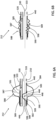
- FIG. 3A-D are schematic illustrations of distal portion 212 of cleaning catheter 200, in accordance with an application of the present invention.
- FIG. 3B is a cross-sectional view perpendicular to central longitudinal axis 533 of suction lumen 530 taken along a plane 10 which passes through an axial center 11 of lateral opening 448.
- inner membrane 589 is arranged such that:
- Such partial occlusion also inhibits fluid communication between the one or more lateral suction orifices 440 and distal-most suction orifice 444 through suction lumen 530.
- inner membrane 589 is arranged such that collapsible membrane portion 596 assumes the occluding state at least when the gauge pressure is 0.2 atm.
- inner membrane 589 is arranged such that collapsible membrane portion 596 assumes the occluding state at least when the gauge pressure is 0.1 atm.
- the fluid suction flow through distal-most suction orifice 444 is at least 50% less than (e.g., at least 75% less than, such as at least 90% less than, e.g., at least 99% less than) when suction lumen 530 is not occluded by collapsible membrane portion 596, when suction lumen 530 is connected to a suction source 601 of the same power.
- Figs. 3A and 3B show a configuration of a resting state of collapsible membrane portion 596, in which inflatable chamber 587 is at ambient pressure (i.e., no inflation pressure and no deflation suction is applied to the one or more fluid-delivery inflation lumens 520).
- ambient pressure i.e., no inflation pressure and no deflation suction is applied to the one or more fluid-delivery inflation lumens 520.
- collapsible membrane portion 596 when inflatable chamber 587 is at ambient pressure, collapsible membrane portion 596 is biased to assume a bulged state, in which collapsible membrane portion 596 is shaped so as to define a bulge portion 602 having a greatest bulge distance D B from seal perimeter 583 of at least 1 mm (e.g., at least 1.5 mm, such as at least 2 mm), measured radially outward (as shown) or radially inward (configuration not shown) from seal perimeter 583.
- bulge portion 602 bulges radially outward and not radially inward (as shown), while for other applications, bulge portion 602 bulges radially inward and not radially outward (configuration not shown).
- radially outward means away from central longitudinal axis 533 of suction lumen 530 and “radially inward” means toward central longitudinal axis 533 of suction lumen 530.
- the resting surface height of inflatable-element outer wall 590 is high enough to accommodate the full extent of the collapsible membrane bulge portion 602 (in contrast with the configuration described hereinbelow with reference to Fig. 6C ).
- inflatable-element outer wall 590 and inner membrane 589 are arranged such that at least when inflatable chamber 587 assumes the bulged state, collapsible membrane portion 596 does not touch an inner surface 604 of inflatable-element outer wall 590 (and also does not touch inner surface 600 of suction lumen 530) (as mentioned above, for some applications, bulge portion 602 bulges radially outward (as shown), while for other applications, bulge portion 602 bulges radially inward (configuration not shown)).
- inflatable-element outer wall 590 and inner membrane 589 may be arranged such that when inflatable chamber 587 assumes the bulged state, greatest bulge distance D B is at least 20% less than a greatest inflatable-element-outer-wall distance D W from seal perimeter 583, measured radially outward from seal perimeter 583.
- Fig. 3C shows the occluding state of collapsible membrane portion 596, in which positive gauge pressure (greater than ambient atmospheric pressure) is applied through the one or more fluid-delivery inflation lumens 520.
- the positive gauge pressure may be a gauge pressure of 0.5 atm, such as 0.2 atm, e.g., 0.1 atm.
- collapsible membrane portion 596 inverts when in the occluding state, as shown in Fig. 3C .
- inflatable element 588 expands only slightly upon inflation, i.e., it has a resting diameter that is similar to the tracheal tube diameter. More generally, in some other applications, the resting diameter of inflatable element 588 is less than the diameter of tracheal ventilation tube 160 and greater than the diameter of catheter body 210.
- collapsible membrane portion 596 is axially surrounded by inflatable chamber 587, i.e., inflatable chamber 587 extends both distally and proximally beyond collapsible membrane portion 596.
- lateral opening 448 is axially surrounded by inflatable chamber 587.
- collapsible membrane portion 596 does not need to stretch much or at all in order to come into contact with inner surface 600 of suction lumen 530 in order to at least partially occlude suction lumen 530.
- occlusion of suction lumen 530 is not very sensitive to the inflation pressure. For example, providing only 0.2 atm inflation gauge pressure may be sufficient to cause collapsible membrane portion 596 to come into contact with inner surface 600 of suction lumen 530 in order to at least partially occlude suction lumen 530.
- collapsible membrane portion 596 typically penetrates deeply enough into suction lumen 530 across central longitudinal axis 533 so as to touch the full perimeter of inner surface 600 of suction lumen 530 at at least one axial location alongside lateral opening 448.
- the bulge area of inner membrane 589 is characterized by the area in which inner membrane 589 does not touch catheter body 210 when collapsible membrane portion 596 is in the resting state.
- a bulge area portion 599 includes a location having a height h measured radially outwards along a radial line 20 from axial center 11 of lateral opening 448. Going around the catheter, bulge area portion 599 ends where inner membrane 589 comes into contact with the catheter body 210.
- An angle ⁇ between line 20 and line 21 is an angular window of bulge portion 602.
- angle ⁇ is less than 60 degrees.
- angle ⁇ may be less than 45 degrees or less than 30 degrees.
- Fig. 3D shows inflatable chamber 587 in a collapsed state.
- inflatable-element outer wall 590 and inner membrane 589 are arranged such that at least when inflatable chamber 587 is at a negative gauge pressure of 0.2 atm, inflatable chamber 587 assumes a collapsed state, in which collapsible membrane portion 596 is drawn at least partially (e.g., so that collapsible membrane portion 596 does not cross central longitudinal axis 533 of suction lumen 530), such as entirely, out of suction lumen 530 and only partially touches inner surface 604 of inflatable-element outer wall 590 (e.g., touches less than 90%, such as less than 80%, e.g., less than 70%, of inner surface 604).
- the occlusion of suction lumen 530 is thus reversible. Because of the excess surface area of collapsible membrane portion 596, collapsible membrane portion 596 is typically crumpled with folds.
- a surface area of collapsible membrane portion 596 varies by less than 30% (e.g., less than 20%, such as less than 10% or less than 5%) between when inflatable chamber 587 is at ambient pressure, such as shown in Figs. 3A and 3B , and when inflatable chamber 587 is at a positive gauge pressure of 0.5 atm, such as shown in Fig. 3C .
- inner membrane 589 is arranged such that when proximal longitudinal portion 532 of suction lumen 530 is in the fluid communication with suction source 601 and suction source 601 provides suction at negative 0.1 atm gauge pressure:
- inner membrane 589 comprises a tube 606 that has (a) a central portion that does not have cylindrical symmetry and/or has an anisotropic shape, and (b) proximal and distal portions proximally and distally beyond collapsible membrane portion 596 that have cylindrical symmetry.
- a circumferential portion 591 of inner membrane 589 snugly touches a circumferential portion of outer lateral wall 592 of catheter body 210 (e.g., which circumferential portion does not define lateral opening 448), and bulge portion 602 bulges radially outward from catheter body 210.
- Inner membrane 589 is positioned and oriented such that collapsible membrane portion 596 covers lateral opening 448.
- inner membrane 589 entirely surrounds catheter body 210; for example, inner membrane 589 may comprise tube 606 that has (a) a central portion that does not have cylindrical symmetry, and (b) proximal and distal portions proximally and distally beyond collapsible membrane portion 596 that have cylindrical symmetry, such as described hereinabove with reference to Figs. 4A-B and 5 .
- Forming inner membrane 589 from tube 606 may substantially simplify manufacturing of cleaning catheter 200 compared to manufacturing collapsible membrane portion 596 from a non-tubular piece of material and attaching (e.g., gluing) it to seal perimeter 583.
- tube 606 may be initially entirely cylindrical, and then the central portion of tube 606 may be deformed to define collapsible membrane portion 596 (e.g., bulge portion 602), while leaving the proximal and distal portions of tube 606 cylindrical.
- Tube 606 may then be mounted on catheter body 210, and the cylindrical proximal and distal portions of the tube may be attached to catheter body 210 on both axial sides (proximal and distal) of lateral opening 448.
- Circumferential portion 591 of inner membrane 589 snugly touches (e.g., is cylindrical and tightly wrapped around, and does not define any folds) a circumferential portion of outer lateral wall 592 of catheter body 210 (e.g., which circumferential portion does not define lateral opening 448).
- Circumferential portion 591 typically is a portion of inner membrane 589 that is farther from axial center 11 of lateral opening 448 than from a point 446 on central longitudinal axis 533 of suction lumen 530 closest to axial center 11.
- Circumferential portion 591 typically surrounds at least 180 degrees of catheter body 210 and/or less than 270 degrees of catheter body 210 (the degrees being measured from rays radiating from central longitudinal axis 533 of suction lumen 530).
- collapsible membrane portion 596 surrounds at least 60 degrees of catheter body 210 and/or less than 180 degrees of catheter body 210 (the degrees being measured from rays radiating from central longitudinal axis 533 of suction lumen
- bulge portion 602 typically at least 30%, such as at least 50%, of the membrane area of bulge portion 602 is self-biased to bulge outwards.
- bulge portion 602 may comprise bulge area portion 599 of inner membrane 589 which is radially (with respect to central longitudinal axis 533 of suction lumen 530) above lateral opening 448.
- the height h of bulge portion 602, measured radially outwards from axial center 11 of lateral opening 448, is at least 50% of the diameter of suction lumen 530, such as at least 100% of the diameter of suction lumen 530.
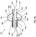
- FIGs. 6A-C are schematic illustration of another configuration of distal portion 212 of cleaning catheter 200, in accordance with an application of the present invention.
- Fig. 6A shows the occluding state of collapsible membrane portion 596, in which positive gauge pressure (greater than ambient atmospheric pressure) is applied through the one or more fluid-delivery inflation lumens 520.
- Fig. 6B shows inflatable chamber 587 in a collapsed state (which is assumed at least when inflatable chamber 587 is at a negative gauge pressure of 0.2 atm). In this configuration, lateral opening 448 only partially axially overlaps inflatable chamber 587 of inflatable element 588.
- Fig. 6C shows the resting state of collapsible membrane portion 596, in which inflatable chamber 587 is at ambient pressure (i.e., no inflation pressure and no deflation suction is applied to the one or more fluid-delivery inflation lumens 520).
- the height of inflatable-element outer wall 590 is not high enough to accommodate the full extent of the collapsible membrane bulge portion 602.
- inflatable-element outer wall 590 and inner membrane 589 are arranged such that at least when collapsible membrane portion 596 assumes the bulged state, collapsible membrane portion 596 touches an inner surface of inflatable-element outer wall 590.
- Figs. 3A-B are schematic illustrations of an alternative configuration distal portion 212 of cleaning catheter 200, in accordance with an application of the present invention.
- lateral opening 448 is formed as a "top" hole into suction lumen 530 (such as by puncturing from above), such that the side walls of the suction lumen at the axial location of the opening are relatively high and substantially complete.
- Figs. 7A-B In the configuration shown in Figs. 7A-B , lateral opening 448 is formed as a "top" hole into suction lumen 530 (such as by puncturing from above), such that the side walls of the suction lumen at the axial location of the opening are relatively high and substantially complete.
- Figs. 7A-B are schematic illustrations of an alternative configuration distal portion 212 of cleaning catheter 200, in accordance with an application of the present invention.
- lateral opening 448 is formed as a "top" hole into suction lumen 530 (such as by puncturing from above), such that the side walls of the suction
- lateral opening 448 is formed as a sideways "bite" into the catheter region of suction lumen 530, such that the side walls of the suction lumen at the axial location are relatively low.
- the "bite” extends down to, and optionally below, the widest level of the suction lumen.
- the lateral opening "bite” extends down at least to the full diameter level at half height of the suction lumen (i.e., to the level of central longitudinal axis 533 of suction lumen 530).
- inflatable element 588 When inflated, inflatable element 588 typically provides two types of functionality: (i) flow obstruction functionality to significantly hinder fluid flow between locations on opposite longitudinal sides of inflatable element 588, and/or (ii) wiping functionality useful for cleaning the inner surface of ventilation tube 160.
- flow obstruction functionality to significantly hinder fluid flow between locations on opposite longitudinal sides of inflatable element 588
- wiping functionality useful for cleaning the inner surface of ventilation tube 160.
- cleaning system 100 operates in a closed system environment.
- cleaning system 100 cleans the inner surface of ventilation tube 160 when ventilation tube-connector assembly 158 mediates a substantially air-tight seal between (i) ventilator 170 and/or an interior of ventilator port 664 and (ii) an interior of ventilation tube 160 and/or an interior of the ventilation tube port.
- inflatable element 588 may be positioned within ventilation tube 160 (e.g., in a distal portion of ventilation tube 160), for example by moving a distal end of catheter body 210 in a distal direction towards a distal end of ventilation tube 160.
- inflatable element 588 may be distally advanced when inflatable element 588 is in a non-contact state (i.e., not in contact with the inner surface of ventilation tube 160).
- inflatable element 588 After inflatable element 588 is thus positioned, inflation of inflatable element 588 induces contact between inflatable-element outer wall 590 and the inner surface of ventilation tube 160 and/or obstructs (i.e., substantially hinders) longitudinal flow between proximal and distal portions of the interior of ventilation tube 160.
- the inflated inflatable element forms a sliding boundary which obstructs (i.e., substantially hinders) fluid flow to between: (a) a more proximal portion of an interstitial region outside of catheter body 210 and within ventilation tube 160 and (b) locations within the ventilation tube 160 that are distal to the slidable boundary formed and delineated by inflatable element 588.
- This slidable boundary between the proximal and distal portions may be useful for facilitating the cleaning of the inner surface of ventilation tube 160 (by wiping), for example for substantially confining locations of negative pressure and/or fluid (e.g., pressurized fluid) introduced into an interstitial region outside of catheter body 210 and within ventilation tube 160 so that the suction is introduced predominantly in the proximal portion of ventilation tube 160.
- negative pressure and/or fluid e.g., pressurized fluid
- cleaning catheter 200 configured as described with reference to Figs. 1-5 is used to modulate relative levels of suction delivered by suction lumen 530 to (a) distal-most suction orifice 444 and (b) the one or more lateral suction orifices 440 between at least two levels that include:
- the level of suction delivered to distal-most suction orifice 444 is less than 10% of the level of suction delivered to the one of the one or more lateral suction orifices 440 having the greatest cross-sectional area, and, at the relatively high distal-most level, the level of suction delivered to distal-most suction orifice 444 is greater than 10% of the level of suction delivered to the one of the one or more lateral suction orifices 440 having the greatest cross-sectional area.
- substantially no suction is delivered to distal-most suction orifice 444.
- catheter body 210 In configuration in which catheter body 210 is not shaped so as to define any proximal lateral suction orifices 440, the high level of suction flow occurs when inflatable element 588 is in a deflated state, and the low levels of suction flow occur when inflatable element 588 is in the inflated state.
- inflatable element 588 and inflatable chamber 587 are inflated via one or more fluid-delivery inflation lumens 520, as shown in Figs. 3A-D .
- inner membrane 589 and inflatable element 588 are positioned at different axial locations along catheter body 210.
- inner membrane 589 defines inflatable chamber 587 with an inner surface of one of the one or more fluid-delivery inflation lumens 520, rather than with inflatable element 588.
- inflatable chamber 587 and inflatable element 588 are inflated via the same lumen.
- they are inflated via different lumens, which may or may not be in fluid communication either along catheter body 210 and/or in a flow regulator 700 (shown in Fig. 2 ).
- a method which optionally uses the configuration of cleaning catheter 200 described hereinabove with reference to Figs. 1-5 , comprises:
- modulating comprises modulating the relative levels of suction between at least two levels that include:
- modulating comprises modulating the relative levels of suction between the at least two levels that include:
- modulating the relative levels of suction comprises reversibly modulating a level of occlusion of at least one of the one or more suction lumens 530 at a portion thereof axially between (x) distal-most suction orifice 444 and (y) the one or more lateral suction orifices 440.
- modulating the relative levels of suction comprises reversibly modulating a level of occlusion of suction lumen 530 at a portion thereof axially between (a) distal-most suction orifice 444 and optionally (b) one or more lateral suction orifices 440.
- the method further comprises, before modulating the relative levels of suction, inserting distal portion 212 of cleaning catheter 200 into tracheal ventilation tube 160 inserted in a trachea of a patient.
- the cleaning action typically comprises the following steps, which are typically performed in the following order:
- Cleaning system 100 may also be used for suctioning the trachea outside of and distal to tracheal ventilation tube 160 when inflatable chamber 587 is not inflated. Collapsible membrane portion 596 thus does not substantially occlude suction lumen 530, such that the applied suction is applied mostly or entirely to distal-most suction orifice 444.
- each of the verbs, "comprise,” “include” and “have,” and conjugates thereof, are used to indicate that the object or objects of the verb are not necessarily a complete listing of members, components, elements or parts of the subject or subjects of the verb.
- the articles “a” and “an” are used herein to refer to one or to more than one (i.e., to at least one) of the grammatical object of the article.
- an element means one element or more than one element.
- the term “including” is used herein to mean, and is used interchangeably with, the phrase “including but not limited to.”
- the term “or” is used herein to mean, and is used interchangeably with, the term “and/or,” unless context clearly indicates otherwise.
- the term “such as” is used herein to mean, and is used interchangeably, with the phrase “such as but not limited to.”
Landscapes
- Health & Medical Sciences (AREA)
- Pulmonology (AREA)
- Emergency Medicine (AREA)
- Engineering & Computer Science (AREA)
- Anesthesiology (AREA)
- Biomedical Technology (AREA)
- Heart & Thoracic Surgery (AREA)
- Hematology (AREA)
- Life Sciences & Earth Sciences (AREA)
- Animal Behavior & Ethology (AREA)
- General Health & Medical Sciences (AREA)
- Public Health (AREA)
- Veterinary Medicine (AREA)
- Otolaryngology (AREA)
- External Artificial Organs (AREA)
- Surgical Instruments (AREA)
- Infusion, Injection, And Reservoir Apparatuses (AREA)
Claims (15)
- Vorrichtung zur Verwendung mit einer Saugquelle, wobei die Vorrichtung einen Reinigungskatheter umfasst, der Folgendes umfasst:einen länglichen, röhrenförmigen Katheterkörper, der so geformt ist, dass er Folgendes definiert: (a) eine distalste Saugöffnung, (b) ein Sauglumen, das (i) entlang des Katheterkörpers zumindest teilweise innerhalb des Katheterkörpers angeordnet ist und (ii) einen proximalen Längsabschnitt, der in Fluidverbindung mit der Saugquelle gekoppelt werden kann, und (c) eine äußere Seitenwand, die so geformt ist, dass sie eine seitliche Öffnung durch sie hindurch in das Sauglumen definiert, wobei die seitliche Öffnung distal zum proximalen Längsabschnitt des Sauglumens angeordnet ist;ein aufblasbares Element, das eine Außenwand des aufblasbaren Elements umfasst und am Katheterkörper angebracht ist; undeine Innenmembran, die:sich zumindest teilweise im Inneren des aufblasbaren Elements befindet und am Katheterkörper um die seitliche Öffnung herum entlang eines luftdichten Dichtungsumfangs angebracht ist, der die seitliche Öffnung umgibt, so dass ein zusammenfaltbarer Membranabschnitt definiert wird, der die seitliche Öffnung abdeckt, und zusammen mit der Außenwand des aufblasbaren Elements eine aufblasbare Kammer zwischen der Außenwand des aufblasbaren Elements und dem zusammenfaltbaren Membranabschnitt definiert, dadurch gekennzeichnet, dass die Innenmembranden Katheterkörper vollständig umgibt undso angeordnet ist, dass zumindest dann, wenn die aufblasbare Kammer unter Umgebungsdruck steht, der proximale Längsabschnitt des Sauglumens in Fluidverbindung mit der distalsten Saugöffnung steht und der zusammenfaltbare Membranabschnitt vorgespannt ist, um einen vorgewölbten Zustand anzunehmen.
- Die Vorrichtung nach Anspruch 1, wobei ein Umfangsabschnitt der inneren Membran einen Umfangsabschnitt der äußeren Seitenwand des Katheterkörpers eng berührt, wobei der Umfangsabschnitt nicht die seitliche Öffnung definiert.
- Die Vorrichtung nach Anspruch 1,wobei der Dichtungsumfang eine gerade Strecke zwischen zwei Punkten auf dem Dichtungsumfang definiert, die am weitesten voneinander entfernt sind, undwobei die Innenmembran so angeordnet ist, dass der zusammenfaltbare Membranabschnitt überschüssiges Material aufweist, das die seitliche Öffnung abdeckt, so dass eine Gesamtlänge eines kürzesten Weges entlang des zusammenfaltbaren Membranabschnitts zwischen den beiden am weitesten voneinander entfernten Punkten auf dem Dichtungsumfang der seitlichen Öffnung mindestens 120 % der geraden Entfernung zwischen den beiden Punkten entspricht, zumindest wenn die aufblasbare Kammer unter Umgebungsdruck steht.
- Die Vorrichtung nach Anspruch 1, wobei der Katheterkörper so geformt ist, dass er eine oder mehrere seitliche Saugöffnungen definiert, die proximal zum aufblasbaren Element angeordnet sind und in Fluidverbindung mit dem Sauglumen stehen.
- Die Vorrichtung nach Anspruch 1, wobei der zusammenfaltbare Membranabschnitt zumindest dann, wenn die aufblasbare Kammer Umgebungsdruck aufweist, axial von der aufblasbaren Kammer umgeben ist.
- Die Vorrichtung nach einem der Ansprüche 1 bis 5, wobei die Innenmembran so angeordnet ist, dass zumindest dann, wenn die aufblasbare Kammer einen Überdruck von 0,5 atm aufweist, der zusammenfaltbare Membranabschnitt einen verschließenden Zustand annimmt, in dem der zusammenfaltbare Membranabschnitt zumindest teilweise eine Innenfläche des Sauglumens gegenüber der seitlichen Öffnung berührt, wodurch das Sauglumen zumindest teilweise verschlossen wird und ein Niveau des Saugfluidflusses in das Sauglumen durch die distalste Saugöffnung moduliert wird.
- Die Vorrichtung nach einem der Ansprüche 1 bis 5, wobei der zusammenfaltbare Membranabschnitt so geformt ist, dass er einen Ausbuchtungsabschnitt mit einem größten Ausbuchtungsabstand von dem Dichtungsumfang von mindestens 1 mm definiert, gemessen radial nach außen oder radial nach innen von dem Dichtungsumfang, wenn der zusammenfaltbare Membranabschnitt den vorgewölbten Zustand annimmt.
- Die Vorrichtung nach einem der Ansprüche 1 bis 7, wobei die Außenwand des aufblasbaren Elements und die Innenmembran so angeordnet sind, dass zumindest dann, wenn der zusammenfaltbare Membranabschnitt den vorgewölbten Zustand annimmt, der zusammenfaltbare Membranabschnitt eine Innenfläche der Außenwand des aufblasbaren Elements berührt.
- Die Vorrichtung nach einem der Ansprüche 1 bis 7, wobei die Außenwand des aufblasbaren Elements und die Innenmembran so angeordnet sind, dass zumindest dann, wenn der zusammenfaltbare Membranabschnitt den vorgewölbten Zustand annimmt, der zusammenfaltbare Membranabschnitt eine Innenfläche der Außenwand des aufblasbaren Elements nicht berührt.
- Die Vorrichtung nach einem der Ansprüche 1 bis 5, wobei der zusammenfaltbare Membranabschnitt eine Innenfläche der Außenwand des aufblasbaren Elements berührt, wenn die aufblasbare Kammer Umgebungsdruck aufweist.
- Die Vorrichtung nach einem der Ansprüche 1 bis 5, wobei die Außenwand des aufblasbaren Elements und die Innenmembran so angeordnet sind, dass zumindest dann, wenn die aufblasbare Kammer einen negativen Überdruck von 0,2 atm aufweist, der zusammenfaltbare Membranabschnitt mit Falten geknittert ist.
- Die Vorrichtung nach Anspruch 11, wobei ein Umfangsabschnitt der inneren Membran einen Umfangsabschnitt der äußeren Seitenwand des Katheterkörpers eng berührt, wobei der Umfangsabschnitt nicht die seitliche Öffnung definiert.
- Die Vorrichtung nach einem der Ansprüche 1 bis 5, wobei die Außenwand des aufblasbaren Elements und die Innenmembran so angeordnet sind, dass zumindest dann, wenn die aufblasbare Kammer einen negativen Überdruck von 0,2 atm aufweist, die aufblasbare Kammer einen zusammengefalteten Zustand annimmt, in dem der zusammenfaltbare Membranabschnitt eine Innenfläche der Außenwand des aufblasbaren Elements nur teilweise berührt.
- Die Vorrichtung nach Anspruch 13, wobei der zusammenfaltbare Membranabschnitt so geformt ist, dass er einen Ausbuchtungsabschnitt mit einem größten Ausbuchtungsabstand von dem Dichtungsumfang von mindestens 1 mm definiert, gemessen radial nach außen oder radial nach innen von dem Dichtungsumfang, wenn der zusammenfaltbare Membranabschnitt den vorgewölbten Zustand annimmt.
- Die Vorrichtung nach Anspruch 13,wobei die Innenmembran so angeordnet ist, dass zumindest dann, wenn die aufblasbare Kammer einen Überdruck von 0,5 atm aufweist, der zusammenfaltbare Membranabschnitt einen verschließenden Zustand annimmt, in dem der zusammenfaltbare Membranabschnitt zumindest teilweise eine Innenfläche des Sauglumens gegenüber der seitlichen Öffnung berührt, wodurch das Sauglumen zumindest teilweise verschlossen wird und ein Niveau des Saugfluidflusses in das Sauglumen durch die distalste Saugöffnung moduliert wird, undwobei die Innenmembran so angeordnet ist, dass, wenn der proximale Längsabschnitt des Sauglumens in Fluidverbindung mit der Saugquelle steht und die Saugquelle einen Sog bei einem negativen Überdruck von 0,1 atm bereitstellt: ein erster Pegel des Saugfluidflusses durch die distalste Saugöffnung fließt, wenn sich der zusammenfaltbare Membranabschnitt im Okkludierzustand befindet,ein zweiter Pegel des Saugfluidflusses durch die distalste Saugöffnung fließt, wenn sich der zusammenfaltbare Membranabschnitt im zusammengefalteten Zustand befindet, undder erste Pegel des Sogs weniger als 50 % des zweiten Pegels des Sogs beträgt.
Applications Claiming Priority (3)
| Application Number | Priority Date | Filing Date | Title |
|---|---|---|---|
| US201662336753P | 2016-05-16 | 2016-05-16 | |
| US201662376102P | 2016-08-17 | 2016-08-17 | |
| PCT/IL2017/050546 WO2017199248A1 (en) | 2016-05-16 | 2017-05-16 | Catheter dynamic tip occlusion |
Publications (4)
| Publication Number | Publication Date |
|---|---|
| EP3458123A1 EP3458123A1 (de) | 2019-03-27 |
| EP3458123A4 EP3458123A4 (de) | 2020-02-12 |
| EP3458123B1 true EP3458123B1 (de) | 2025-04-23 |
| EP3458123C0 EP3458123C0 (de) | 2025-04-23 |
Family
ID=60324870
Family Applications (1)
| Application Number | Title | Priority Date | Filing Date |
|---|---|---|---|
| EP17798884.7A Active EP3458123B1 (de) | 2016-05-16 | 2017-05-16 | Dynamische katheterspitzenokklusion |
Country Status (7)
| Country | Link |
|---|---|
| US (2) | US20190160245A1 (de) |
| EP (1) | EP3458123B1 (de) |
| JP (2) | JP6743189B2 (de) |
| CN (2) | CN109475668B (de) |
| AU (1) | AU2017267625B2 (de) |
| PL (1) | PL3458123T3 (de) |
| WO (1) | WO2017199248A1 (de) |
Families Citing this family (10)
| Publication number | Priority date | Publication date | Assignee | Title |
|---|---|---|---|---|
| GB201119794D0 (en) | 2011-11-16 | 2011-12-28 | Airway Medix Spolka Z O O | Ballooned ventilation tube cleaning device |
| US10322253B2 (en) | 2011-03-29 | 2019-06-18 | Teleflex Life Sciences Unlimited Company | Ballooned ventilation tube cleaning device |
| EP2754461B1 (de) | 2013-01-14 | 2017-12-13 | Teleflex Medical Incorporated | Absaugkathetervorrichtung |
| US10500360B1 (en) | 2014-08-29 | 2019-12-10 | Teleflex Life Sciences Unlimited Company | Catheter for cleaning of tracheal ventilation tubes |
| US11452831B2 (en) | 2016-01-06 | 2022-09-27 | Airway Medix S.A. | Closed suction system |
| GB2546082B (en) | 2016-01-06 | 2018-05-16 | Airway Medix S A | Closed suction system |
| US10946153B2 (en) | 2016-05-16 | 2021-03-16 | Teleflex Life Sciences Pte. Ltd. | Mechanical user control elements for fluid input module |
| EP3458123B1 (de) | 2016-05-16 | 2025-04-23 | Airway Medix S.A. | Dynamische katheterspitzenokklusion |
| USD839118S1 (en) * | 2016-12-29 | 2019-01-29 | Vpas Group Pty Ltd | Gas flow indicator device |
| AU201617379S (en) * | 2016-12-29 | 2017-01-25 | Vpas Group Pty Ltd | Gas Flow Indicator Device |
Family Cites Families (136)
| Publication number | Priority date | Publication date | Assignee | Title |
|---|---|---|---|---|
| US3211152A (en) | 1961-11-15 | 1965-10-12 | Ernest A Stern | Safety endotracheal tube cuff |
| US3211150A (en) | 1963-08-15 | 1965-10-12 | Foderick John Walter | Balloon catheter with integral valves controlling inflation |
| US3502069A (en) | 1965-10-20 | 1970-03-24 | Daniel Silverman | Method and apparatus for placing in and retrieving a tubular probe from a body cavity |
| US3671979A (en) | 1969-09-23 | 1972-06-27 | Univ Utah | Catheter mounted artificial heart valve for implanting in close proximity to a defective natural heart valve |
| US3780736A (en) | 1972-10-20 | 1973-12-25 | A Chen | Surgical valve assembly for urinary bladder irrigation and drainage |
| US3848605A (en) * | 1973-04-23 | 1974-11-19 | American Hospital Supply Corp | Endotracheal tube with improved inflation retention means |
| US4240433A (en) | 1977-07-22 | 1980-12-23 | Bordow Richard A | Fluid aspiration device and technique for reducing the risk of complications |
| US4324262A (en) | 1979-01-02 | 1982-04-13 | University Of Virginia Alumni Patents Foundation | Aspirating culture catheter and method of use |
| US4245639A (en) | 1979-04-30 | 1981-01-20 | C. R. Bard, Inc. | Self-inflating urinary catheter |
| US4469100A (en) | 1983-03-14 | 1984-09-04 | Hardwick Charles W | Intussuscepting balloon catheter for stone extraction |
| US4606347A (en) | 1983-03-25 | 1986-08-19 | Thomas J. Fogarty | Inverted balloon catheter having sealed through lumen |
| US4555242A (en) | 1984-01-19 | 1985-11-26 | Saudagar Abdul S | Urinary drainage appliance |
| US4569344A (en) | 1984-07-23 | 1986-02-11 | Ballard Medical Products | Aspirating/ventilating apparatus and method |
| US5215522A (en) | 1984-07-23 | 1993-06-01 | Ballard Medical Products | Single use medical aspirating device and method |
| US5277177A (en) | 1984-07-23 | 1994-01-11 | Ballard Medical Products | Single use medical aspirating device and method |
| JPS62211074A (ja) * | 1986-03-07 | 1987-09-17 | ボ−ド・オブ・リ−ジエンツ、ザ・ユニバ−シテイ−・オブ・テキサス・システム | 先端バル−ン付き吸引カテ−テル |
| US4734094A (en) * | 1986-06-09 | 1988-03-29 | Jacob Erwin T | Catheter and method for cholangiography |
| US4691702A (en) | 1986-10-08 | 1987-09-08 | Becton, Dickinson And Company | Aspirating device |
| US4961738A (en) | 1987-01-28 | 1990-10-09 | Mackin Robert A | Angioplasty catheter with illumination and visualization within angioplasty balloon |
| JP2620250B2 (ja) * | 1987-04-27 | 1997-06-11 | ボード・オブ・リージェンツ、ザ・ユニバーシティー・オブ・テキサス・システム | カテーテルアッセンブリ |
| US4886496A (en) * | 1988-02-04 | 1989-12-12 | Conoscenti Craig S | Bronchoscopic balloon tipped catheter and method of making the same |
| US4805611A (en) | 1988-02-10 | 1989-02-21 | Becton, Dickinson And Company | Aspirating device |
| US4946440A (en) | 1988-10-05 | 1990-08-07 | Hall John E | Evertible membrane catheter and method of use |
| US5101817A (en) | 1989-08-04 | 1992-04-07 | Nellcor, Inc. | Airway adapter for use with closed suction catheter system |
| US5073164A (en) | 1990-05-02 | 1991-12-17 | Hollister William H | Suction catheter |
| US5360403A (en) * | 1990-05-16 | 1994-11-01 | Lake Region Manufacturing Co., Inc. | Balloon catheter with lumen occluder |
| US5139018A (en) | 1990-07-24 | 1992-08-18 | Superior Healthcare Group, Inc. | Patient ventilating apparatus with aspirating catheter |
| US5181908A (en) | 1990-12-07 | 1993-01-26 | Smiths Industries Medical Systems Inc. | Method and apparatus for lavaging with oxygenated irrigating fluid while suctioning |
| US5134996A (en) | 1991-01-09 | 1992-08-04 | Smiths Industries Medical Systems, Inc. | Inspiration and expiration indicator for a suction catheter |
| US5325851A (en) | 1991-04-01 | 1994-07-05 | Sorenson Laboratories, Inc. | Apparatus and method for ventilating and aspirating |
| US5188618A (en) | 1991-05-03 | 1993-02-23 | Thomas Bruce W | Thrombus-mobilizing thoracostomy tube |
| US5364345A (en) | 1991-10-18 | 1994-11-15 | Imagyn Medical, Inc. | Method of tubal recanalization and catheter system therefor |
| US5364358A (en) | 1991-11-05 | 1994-11-15 | Cardio-Search Limited | Device for controlling the inflation of a balloon catheter |
| US5250029A (en) * | 1991-11-06 | 1993-10-05 | Edward Lin | Zero-residual zero-tip balloon catheter |
| US5309902A (en) | 1992-10-19 | 1994-05-10 | Sherwood Medical Company | Respiratory support system and suction catheter device therefor |
| US6540764B1 (en) | 1992-06-02 | 2003-04-01 | General Surgical Innovations, Inc. | Apparatus and method for dissecting tissue layers |
| US5337730A (en) | 1992-06-18 | 1994-08-16 | The United States Of America As Represented By The Secretary Of The Air Force | Endoscope cleansing catheter and method of use |
| US5431637A (en) * | 1992-07-31 | 1995-07-11 | Sherwood Medical Company | Endotracheal suction catheter |
| GB2270845B (en) | 1992-09-24 | 1996-07-10 | Smiths Ind Med Syst Inc | Suction catheter assemblies |
| US5336172A (en) | 1992-10-09 | 1994-08-09 | Symbiosis Corporation | Endoscopic suction-irrigation instrument having insertible probes with lateral ports |
| US5349950A (en) | 1992-10-28 | 1994-09-27 | Smiths Industries Medical Systems, Inc. | Suction catheter assemblies |
| US5254098A (en) | 1993-02-16 | 1993-10-19 | Smiths Industries Medical Systems, Inc. | Suction catheter assemblies |
| US5490503A (en) | 1994-04-29 | 1996-02-13 | Smiths Industries Medical Systems, Inc. | Suction catheter having multiple valves and collet assembly |
| US5694922A (en) | 1994-05-18 | 1997-12-09 | Ballard Medical Products | Swivel tube connections with hermetic seals |
| JP3782123B2 (ja) | 1994-05-31 | 2006-06-07 | 住友ベークライト株式会社 | 咽腔用エアウエイ |
| EP0827416A4 (de) | 1995-03-28 | 1999-06-09 | Ballard Med Prod | Katheterhülle mit anti-kontaminationsbarrierren in form von filter bzw. verschluss |
| US5634937A (en) | 1995-05-19 | 1997-06-03 | General Surgical Innovations, Inc. | Skin seal with inflatable membrane |
| US5545179A (en) | 1995-07-21 | 1996-08-13 | Ethicon Endo-Surgery, Inc. | Endoscopic access assembly |
| GB9520234D0 (en) | 1995-10-04 | 1995-12-06 | Smiths Industries Plc | Tracheal tubes and systems |
| US8557054B2 (en) | 1996-03-11 | 2013-10-15 | Orlando Morejon | Endotracheal tube cleaning apparatus |
| US6318368B1 (en) | 1996-03-11 | 2001-11-20 | Orlando Morejon | Endotracheal tube cleaning apparatus |
| US7060135B2 (en) | 1996-03-11 | 2006-06-13 | Orlando Morejon | Endotracheal tube cleaning apparatus and method |
| US6082361A (en) | 1997-09-12 | 2000-07-04 | Morejon; Orlando | Endotracheal tube cleaning apparatus |
| US6494208B1 (en) | 1996-03-11 | 2002-12-17 | Orlando Morejon | Endotracheal tube cleaning apparatus |
| US5709691A (en) | 1996-03-11 | 1998-01-20 | Morejon; Orlando | Endotracheal tube cleaning device |
| US7669600B2 (en) | 1996-03-11 | 2010-03-02 | Orlando Morejon | Endotracheal tube cleaning apparatus |
| WO1999038548A2 (en) | 1998-01-28 | 1999-08-05 | Jaime Vargas | Oral pharyngeal evacuation endotracheal tube |
| US6179827B1 (en) * | 1998-03-16 | 2001-01-30 | Chase Medical | Catheter having integral expandable/collapsible lumen |
| US6227200B1 (en) | 1998-09-21 | 2001-05-08 | Ballard Medical Products | Respiratory suction catheter apparatus |
| US7021313B1 (en) | 1998-09-21 | 2006-04-04 | Ballard Medical Products | Respiratory suction catheter apparatus with improved valve and collar |
| US6364867B2 (en) | 1999-07-01 | 2002-04-02 | Catheter Innovations, Inc. | Anti-clotting methods and apparatus for indwelling catheter tubes |
| MXPA02005898A (es) | 1999-12-13 | 2004-08-12 | Ballard Med Prod | Conjunto de multiple y de cateter endotraqueal con valvula mejorada. |
| JP4330753B2 (ja) | 2000-03-03 | 2009-09-16 | ジョンソン・エンド・ジョンソン株式会社 | 潅流機能付吸引装置 |
| US6575944B1 (en) | 2000-06-19 | 2003-06-10 | Portex, Inc. | Adapter for localized treatment through a tracheal tube and method for use thereof |
| DE10043338A1 (de) | 2000-09-02 | 2002-03-14 | Truetzschler Gmbh & Co Kg | Vorrichtung zum Betreiben einer Speiseeeinrichtung für Fasermaterial, z. B. Kastenspeiser |
| US6923184B1 (en) | 2001-02-05 | 2005-08-02 | Ronald D. Russo | Suction system with high efficiency suction control valve |
| US6979343B2 (en) | 2001-02-14 | 2005-12-27 | Ev3 Inc. | Rolled tip recovery catheter |
| US6976974B2 (en) | 2002-10-23 | 2005-12-20 | Scimed Life Systems, Inc. | Rotary manifold syringe |
| US7172572B2 (en) | 2001-10-04 | 2007-02-06 | Boston Scientific Scimed, Inc. | Manifold system for a medical device |
| US6918893B2 (en) | 2001-10-04 | 2005-07-19 | Scimed Life Systems, Inc. | Multiple port fluid control valves |
| US7204252B2 (en) | 2001-12-21 | 2007-04-17 | Eidon, Llc | Surface energy assisted fluid transport system |
| GB0225075D0 (en) | 2002-10-29 | 2002-12-04 | Smiths Group Plc | Valves |
| AU2004235782B2 (en) | 2003-05-02 | 2009-07-02 | Clearflow, Inc. | Body-space drainage-tube debris removal |
| US7556041B2 (en) | 2003-05-06 | 2009-07-07 | Kimberly-Clark Worldwide, Inc. | Respiratory apparatus having an introduction section configured for releasable attachment with a respiratory instrument |
| US7191782B2 (en) | 2003-05-06 | 2007-03-20 | Kimberly-Clark Worldwide, Inc. | Respiratory suction catheter apparatus configured for releasable attachment with an artificial airway structure |
| DE10333706B4 (de) | 2003-07-23 | 2007-07-12 | Microcuff Gmbh | Verschlußsystem für Anus praeter |
| US7051737B2 (en) | 2004-02-05 | 2006-05-30 | The United States Of America As Represented By The Department Of Health And Human Sevices | Mucus shaving apparatus for endotracheal tubes |
| MXPA06013094A (es) | 2004-05-12 | 2007-05-04 | Nellcor Puritan Bennett Inc | Tubo endotraqueal que tiene lumen ara succion mejorada. |
| DE102004027734A1 (de) | 2004-06-07 | 2005-12-22 | Filtertek B.V., Newcastle West | Vorrichtung zur Verbindung eines Beatmungsgerätes mit dem Patienten |
| US20050279359A1 (en) | 2004-06-17 | 2005-12-22 | Leblanc David M | Oral suction catheter |
| US7188623B2 (en) | 2004-07-07 | 2007-03-13 | Egret Medical Products, Inc. | Suction catheter assembly |
| JP2008520290A (ja) * | 2004-11-19 | 2008-06-19 | サターン バイオメディカル システムズ インコーポレイテッド | 分泌物を除去する換気用カテーテルおよび気道確保システム |
| GB2427142B (en) | 2005-06-13 | 2010-10-20 | Single Use Surgical Ltd | Multi lumen suction irrigator |
| US20060278235A1 (en) | 2005-06-14 | 2006-12-14 | White Steven C | Tracheal tube with above the cuff drainage |
| ITBO20050404A1 (it) | 2005-06-15 | 2006-12-16 | Sherwood Serv Ag | Valvola di accesso broncotracheale per una apparecchiatura di broncoaspirazione |
| US7478636B2 (en) | 2005-08-08 | 2009-01-20 | Kimberly-Clark Worldwide, Inc. | Multilumen tracheal catheter to prevent cross contamination |
| US8114113B2 (en) * | 2005-09-23 | 2012-02-14 | Acclarent, Inc. | Multi-conduit balloon catheter |
| US8002732B2 (en) | 2005-09-27 | 2011-08-23 | Allegiance Corporation | Medical suction and irrigation device |
| US20070089748A1 (en) | 2005-10-26 | 2007-04-26 | Madsen Edward B | Tracheal catheter with closeable suction lumen |
| US7775206B2 (en) | 2006-06-01 | 2010-08-17 | Egret Medical Products, Inc. | Neonate suction catheter assembly |
| GB0612750D0 (en) | 2006-06-28 | 2006-08-09 | Smiths Group Plc | Intubation detector |
| US7789893B2 (en) | 2006-09-12 | 2010-09-07 | Boston Scientific Scimed, Inc. | Method and apparatus for promoting hemostasis of a blood vessel puncture |
| US20080066746A1 (en) | 2006-09-14 | 2008-03-20 | Nelson Lindsey A | Method and device for placing an endotracheal tube |
| WO2008039800A2 (en) | 2006-09-25 | 2008-04-03 | Valentx, Inc. | Toposcopic access and delivery devices |
| WO2008045308A2 (en) | 2006-10-05 | 2008-04-17 | Kumar Anil B | Balloon catheter with manually operated valve and aspirator |
| US8435207B2 (en) | 2006-11-06 | 2013-05-07 | Aardvark Medical, Inc. | Irrigation and aspiration devices and methods |
| GB0623535D0 (en) | 2006-11-25 | 2007-01-03 | Smiths Group Plc | Suction apparatus and connectors |
| US9138552B2 (en) | 2007-06-05 | 2015-09-22 | Cedars-Sinai Medical Center | Closed suctioning and rinsing methods and tracheal devices |
| US8133326B2 (en) | 2008-01-14 | 2012-03-13 | C.R. Bard, Inc. | Endotracheal tube cleaning devices and methods of removing mucus accumulations from endotracheal tubes |
| US8210168B2 (en) | 2008-09-30 | 2012-07-03 | Tyco Healthcare Group Lp | Gastric insertion confirmation device and method of use |
| US20100147309A1 (en) | 2008-12-12 | 2010-06-17 | Cuevas Brian J | Tracheal Catheter With a Flexible Lumen for Subglottic Suctioning |
| US20100147312A1 (en) | 2008-12-12 | 2010-06-17 | John Brewer | Respiratory Access Port Assembly With Pin Lock and Method of Use |
| US8215306B2 (en) | 2008-12-12 | 2012-07-10 | Kimberly-Clark Worldwide, Inc. | Respiratory access port assembly with push button lock and method of use |
| US8468637B2 (en) | 2009-02-06 | 2013-06-25 | Endoclear Llc | Mechanically-actuated endotracheal tube cleaning device |
| EP3329955B1 (de) | 2009-02-06 | 2020-10-21 | Endoclear LLC | Gerät zur reinigung eines endotrachealtubus |
| US8454579B2 (en) * | 2009-03-25 | 2013-06-04 | Icu Medical, Inc. | Medical connector with automatic valves and volume regulator |
| JP2010270064A (ja) | 2009-05-21 | 2010-12-02 | Nagoya Institute Of Technology | ピラゾリジン−3−オン誘導体の製造方法 |
| US8434488B2 (en) | 2009-06-08 | 2013-05-07 | Covidien Lp | Endotracheal tube with dedicated evacuation port |
| US9248249B2 (en) | 2009-06-08 | 2016-02-02 | Covidien Lp | Point-of-care pathogen monitoring devices and systems |
| US9119926B2 (en) | 2009-07-31 | 2015-09-01 | Avent, Inc. | Subglottic suctioning system |
| WO2011022497A1 (en) | 2009-08-20 | 2011-02-24 | C. R. Bard, Inc. | Ventilator attachment fitting usable on a endotracheal tube having an integrally formed suction lumen and method of making and/or using the same |
| EP2531253A1 (de) * | 2009-09-23 | 2012-12-12 | Angioslide Ltd. | Ballonkatheter und verwendungsverfahren dafür |
| CN201516218U (zh) * | 2009-10-27 | 2010-06-30 | 刘磊 | 呼吸与排痰同步分离式气管插管 |
| US20110186052A1 (en) * | 2010-02-01 | 2011-08-04 | Orlando Morejon | Cleaning assembly for an endotracheal tube |
| US20110197894A1 (en) | 2010-02-18 | 2011-08-18 | Orlando Morejon | Endotracheal tube cleaning apparatus |
| US20160199608A1 (en) | 2010-02-18 | 2016-07-14 | Orlando Morejon | System and method of expediting weaning from ventilator support including an artificial airway cleaning apparatus |
| US8783255B2 (en) | 2010-07-30 | 2014-07-22 | Covidien Lp | Medical device tube having suction lumen and an associated suctioning system |
| WO2012087837A1 (en) | 2010-12-21 | 2012-06-28 | C. R. Bard, Inc. | Endotracheal tube having a recessed cuff, one or more suction apertures arranged therein, and/or a cuff having stiffeners and method of making and/or using the same |
| GB201119794D0 (en) | 2011-11-16 | 2011-12-28 | Airway Medix Spolka Z O O | Ballooned ventilation tube cleaning device |
| US8631798B2 (en) | 2011-03-29 | 2014-01-21 | Carefusion 207, Inc. | Valving a respiratory gas pathway with a catheter balloon |
| US10322253B2 (en) | 2011-03-29 | 2019-06-18 | Teleflex Life Sciences Unlimited Company | Ballooned ventilation tube cleaning device |
| US20120289893A1 (en) | 2011-05-11 | 2012-11-15 | Lily Medical Corporation | Suction catheter controller and suction catheter assembly utilizing the same |
| US8784442B2 (en) | 2011-08-19 | 2014-07-22 | Empirilon Technology, Llc | Methods and systems for performing thrombectomy procedures |
| US20130112207A1 (en) | 2011-11-09 | 2013-05-09 | Teleflex Medical Incorporated | Endotracheal tube with dual port subglottic secretion suctioning |
| US9352112B2 (en) | 2011-12-13 | 2016-05-31 | Covidien Lp | Shaped evacuation port for a multi-lumen tracheal tube |
| US9332998B2 (en) * | 2012-08-13 | 2016-05-10 | Covidien Lp | Apparatus and methods for clot disruption and evacuation |
| US9131988B2 (en) | 2012-09-28 | 2015-09-15 | Avent, Inc. | Self positioning tracheal tube clearance mechanism using skives |
| EP2928517B2 (de) | 2012-12-04 | 2025-08-27 | SunMed Group Holdings, LLC | Saugreinigungsvorrichtungen |
| EP2967601B1 (de) * | 2013-03-14 | 2017-11-29 | Boston Scientific Scimed, Inc. | Systeme und vorrichtung zur behandlung von blutgefässen |
| GB201306067D0 (en) | 2013-04-04 | 2013-05-22 | Smiths Medical Int Ltd | Resuscitator arrangements and flow monitoring |
| US10016575B2 (en) * | 2014-06-03 | 2018-07-10 | Endoclear Llc | Cleaning devices, systems and methods |
| CN203989373U (zh) * | 2014-08-20 | 2014-12-10 | 重庆医科大学附属永川医院 | 气管导管 |
| CN104689436A (zh) * | 2015-02-15 | 2015-06-10 | 冯明臣 | 重症室用电控呼吸机 |
| GB2546082B (en) | 2016-01-06 | 2018-05-16 | Airway Medix S A | Closed suction system |
| US10946153B2 (en) | 2016-05-16 | 2021-03-16 | Teleflex Life Sciences Pte. Ltd. | Mechanical user control elements for fluid input module |
| EP3458123B1 (de) | 2016-05-16 | 2025-04-23 | Airway Medix S.A. | Dynamische katheterspitzenokklusion |
-
2017
- 2017-05-16 EP EP17798884.7A patent/EP3458123B1/de active Active
- 2017-05-16 PL PL17798884.7T patent/PL3458123T3/pl unknown
- 2017-05-16 WO PCT/IL2017/050546 patent/WO2017199248A1/en not_active Ceased
- 2017-05-16 CN CN201780042872.6A patent/CN109475668B/zh not_active Expired - Fee Related
- 2017-05-16 JP JP2018560785A patent/JP6743189B2/ja active Active
- 2017-05-16 US US16/301,989 patent/US20190160245A1/en not_active Abandoned
- 2017-05-16 AU AU2017267625A patent/AU2017267625B2/en not_active Ceased
- 2017-05-16 CN CN202110623636.1A patent/CN113546266A/zh active Pending
-
2020
- 2020-07-29 JP JP2020127911A patent/JP7028921B2/ja active Active
-
2022
- 2022-02-23 US US17/678,883 patent/US12539382B2/en active Active
Also Published As
| Publication number | Publication date |
|---|---|
| CN109475668B (zh) | 2021-06-15 |
| PL3458123T3 (pl) | 2025-09-08 |
| JP6743189B2 (ja) | 2020-08-19 |
| EP3458123A4 (de) | 2020-02-12 |
| CN113546266A (zh) | 2021-10-26 |
| AU2017267625B2 (en) | 2021-10-07 |
| WO2017199248A1 (en) | 2017-11-23 |
| JP2020171821A (ja) | 2020-10-22 |
| CN109475668A (zh) | 2019-03-15 |
| JP7028921B2 (ja) | 2022-03-02 |
| US12539382B2 (en) | 2026-02-03 |
| EP3458123C0 (de) | 2025-04-23 |
| US20190160245A1 (en) | 2019-05-30 |
| AU2017267625A1 (en) | 2018-12-20 |
| EP3458123A1 (de) | 2019-03-27 |
| JP2019514634A (ja) | 2019-06-06 |
| US20230009421A1 (en) | 2023-01-12 |
Similar Documents
| Publication | Publication Date | Title |
|---|---|---|
| US12539382B2 (en) | Catheter dynamic tip occlusion | |
| US9131988B2 (en) | Self positioning tracheal tube clearance mechanism using skives | |
| US8535265B2 (en) | Tracheal catheter with suction lumen port in close proximity to the cuff | |
| US10926009B2 (en) | Closed suction system | |
| US7293561B2 (en) | Low profile adapter for tracheal tubes | |
| CN103656813A (zh) | 具有吸液功能的人工气道 | |
| US11452831B2 (en) | Closed suction system | |
| US11992615B2 (en) | Closed suction system | |
| CN214550584U (zh) | 一种插管组件 | |
| EP3880282B1 (de) | Trachealhilfe | |
| WO2020197506A1 (en) | An endotracheal tube and method related to the same |
Legal Events
| Date | Code | Title | Description |
|---|---|---|---|
| STAA | Information on the status of an ep patent application or granted ep patent |
Free format text: STATUS: THE INTERNATIONAL PUBLICATION HAS BEEN MADE |
|
| PUAI | Public reference made under article 153(3) epc to a published international application that has entered the european phase |
Free format text: ORIGINAL CODE: 0009012 |
|
| STAA | Information on the status of an ep patent application or granted ep patent |
Free format text: STATUS: REQUEST FOR EXAMINATION WAS MADE |
|
| 17P | Request for examination filed |
Effective date: 20181213 |
|
| AK | Designated contracting states |
Kind code of ref document: A1 Designated state(s): AL AT BE BG CH CY CZ DE DK EE ES FI FR GB GR HR HU IE IS IT LI LT LU LV MC MK MT NL NO PL PT RO RS SE SI SK SM TR |
|
| AX | Request for extension of the european patent |
Extension state: BA ME |
|
| DAV | Request for validation of the european patent (deleted) | ||
| DAX | Request for extension of the european patent (deleted) | ||
| A4 | Supplementary search report drawn up and despatched |
Effective date: 20200113 |
|
| RIC1 | Information provided on ipc code assigned before grant |
Ipc: A61M 25/18 20060101ALI20200107BHEP Ipc: A61M 1/00 20060101AFI20200107BHEP Ipc: A61M 16/04 20060101ALI20200107BHEP Ipc: A61M 25/14 20060101ALI20200107BHEP |
|
| RAP1 | Party data changed (applicant data changed or rights of an application transferred) |
Owner name: TELEFLEX LIFE SCIENCES PTE. LTD. |
|
| RAP1 | Party data changed (applicant data changed or rights of an application transferred) |
Owner name: AIRWAY MEDIX S.A. |
|
| RAP3 | Party data changed (applicant data changed or rights of an application transferred) |
Owner name: AIRWAY MEDIX S.A. |
|
| GRAP | Despatch of communication of intention to grant a patent |
Free format text: ORIGINAL CODE: EPIDOSNIGR1 |
|
| STAA | Information on the status of an ep patent application or granted ep patent |
Free format text: STATUS: GRANT OF PATENT IS INTENDED |
|
| INTG | Intention to grant announced |
Effective date: 20241120 |
|
| GRAS | Grant fee paid |
Free format text: ORIGINAL CODE: EPIDOSNIGR3 |
|
| GRAA | (expected) grant |
Free format text: ORIGINAL CODE: 0009210 |
|
| STAA | Information on the status of an ep patent application or granted ep patent |
Free format text: STATUS: THE PATENT HAS BEEN GRANTED |
|
| AK | Designated contracting states |
Kind code of ref document: B1 Designated state(s): AL AT BE BG CH CY CZ DE DK EE ES FI FR GB GR HR HU IE IS IT LI LT LU LV MC MK MT NL NO PL PT RO RS SE SI SK SM TR |
|
| RAP3 | Party data changed (applicant data changed or rights of an application transferred) |
Owner name: AIRWAY MEDIX S.A. |
|
| REG | Reference to a national code |
Ref country code: GB Ref legal event code: FG4D |
|
| REG | Reference to a national code |
Ref country code: CH Ref legal event code: EP |
|
| REG | Reference to a national code |
Ref country code: DE Ref legal event code: R096 Ref document number: 602017089066 Country of ref document: DE |
|
| REG | Reference to a national code |
Ref country code: IE Ref legal event code: FG4D |
|
| U01 | Request for unitary effect filed |
Effective date: 20250523 |
|
| U07 | Unitary effect registered |
Designated state(s): AT BE BG DE DK EE FI FR IT LT LU LV MT NL PT RO SE SI Effective date: 20250602 |
|
| PG25 | Lapsed in a contracting state [announced via postgrant information from national office to epo] |
Ref country code: ES Free format text: LAPSE BECAUSE OF FAILURE TO SUBMIT A TRANSLATION OF THE DESCRIPTION OR TO PAY THE FEE WITHIN THE PRESCRIBED TIME-LIMIT Effective date: 20250423 |
|
| PG25 | Lapsed in a contracting state [announced via postgrant information from national office to epo] |
Ref country code: NO Free format text: LAPSE BECAUSE OF FAILURE TO SUBMIT A TRANSLATION OF THE DESCRIPTION OR TO PAY THE FEE WITHIN THE PRESCRIBED TIME-LIMIT Effective date: 20250723 Ref country code: GR Free format text: LAPSE BECAUSE OF FAILURE TO SUBMIT A TRANSLATION OF THE DESCRIPTION OR TO PAY THE FEE WITHIN THE PRESCRIBED TIME-LIMIT Effective date: 20250724 |
|
| PG25 | Lapsed in a contracting state [announced via postgrant information from national office to epo] |
Ref country code: HR Free format text: LAPSE BECAUSE OF FAILURE TO SUBMIT A TRANSLATION OF THE DESCRIPTION OR TO PAY THE FEE WITHIN THE PRESCRIBED TIME-LIMIT Effective date: 20250423 |
|
| PG25 | Lapsed in a contracting state [announced via postgrant information from national office to epo] |
Ref country code: RS Free format text: LAPSE BECAUSE OF FAILURE TO SUBMIT A TRANSLATION OF THE DESCRIPTION OR TO PAY THE FEE WITHIN THE PRESCRIBED TIME-LIMIT Effective date: 20250723 |
|
| PG25 | Lapsed in a contracting state [announced via postgrant information from national office to epo] |
Ref country code: IS Free format text: LAPSE BECAUSE OF FAILURE TO SUBMIT A TRANSLATION OF THE DESCRIPTION OR TO PAY THE FEE WITHIN THE PRESCRIBED TIME-LIMIT Effective date: 20250823 |
|
| REG | Reference to a national code |
Ref country code: CH Ref legal event code: H13 Free format text: ST27 STATUS EVENT CODE: U-0-0-H10-H13 (AS PROVIDED BY THE NATIONAL OFFICE) Effective date: 20251223 |
|
| U21 | Renewal fee for the european patent with unitary effect paid with additional fee |
Year of fee payment: 9 Effective date: 20251127 |
|
| PGFP | Annual fee paid to national office [announced via postgrant information from national office to epo] |
Ref country code: GB Payment date: 20251124 Year of fee payment: 9 |
|
| PG25 | Lapsed in a contracting state [announced via postgrant information from national office to epo] |
Ref country code: SM Free format text: LAPSE BECAUSE OF FAILURE TO SUBMIT A TRANSLATION OF THE DESCRIPTION OR TO PAY THE FEE WITHIN THE PRESCRIBED TIME-LIMIT Effective date: 20250423 |
|
| PG25 | Lapsed in a contracting state [announced via postgrant information from national office to epo] |
Ref country code: CH Free format text: LAPSE BECAUSE OF NON-PAYMENT OF DUE FEES Effective date: 20250531 |
|
| PG25 | Lapsed in a contracting state [announced via postgrant information from national office to epo] |
Ref country code: CZ Free format text: LAPSE BECAUSE OF FAILURE TO SUBMIT A TRANSLATION OF THE DESCRIPTION OR TO PAY THE FEE WITHIN THE PRESCRIBED TIME-LIMIT Effective date: 20250423 |
|
| PGFP | Annual fee paid to national office [announced via postgrant information from national office to epo] |
Ref country code: PL Payment date: 20251117 Year of fee payment: 9 |
|
| PG25 | Lapsed in a contracting state [announced via postgrant information from national office to epo] |
Ref country code: SK Free format text: LAPSE BECAUSE OF FAILURE TO SUBMIT A TRANSLATION OF THE DESCRIPTION OR TO PAY THE FEE WITHIN THE PRESCRIBED TIME-LIMIT Effective date: 20250423 |
|
| PG25 | Lapsed in a contracting state [announced via postgrant information from national office to epo] |
Ref country code: MC Free format text: LAPSE BECAUSE OF FAILURE TO SUBMIT A TRANSLATION OF THE DESCRIPTION OR TO PAY THE FEE WITHIN THE PRESCRIBED TIME-LIMIT Effective date: 20250423 |
|
| PLBE | No opposition filed within time limit |
Free format text: ORIGINAL CODE: 0009261 |
|
| STAA | Information on the status of an ep patent application or granted ep patent |
Free format text: STATUS: NO OPPOSITION FILED WITHIN TIME LIMIT |
|
| REG | Reference to a national code |
Ref country code: CH Ref legal event code: L10 Free format text: ST27 STATUS EVENT CODE: U-0-0-L10-L00 (AS PROVIDED BY THE NATIONAL OFFICE) Effective date: 20260304 |
|
| 26N | No opposition filed |
Effective date: 20260126 |
|
| PG25 | Lapsed in a contracting state [announced via postgrant information from national office to epo] |
Ref country code: IE Free format text: LAPSE BECAUSE OF NON-PAYMENT OF DUE FEES Effective date: 20250516 |