EP3458331B1 - Procédé et dispositif de surveillance d'au moins un composant de voie posé dans la construction de chemin de fer - Google Patents
Procédé et dispositif de surveillance d'au moins un composant de voie posé dans la construction de chemin de fer Download PDFInfo
- Publication number
- EP3458331B1 EP3458331B1 EP17724725.1A EP17724725A EP3458331B1 EP 3458331 B1 EP3458331 B1 EP 3458331B1 EP 17724725 A EP17724725 A EP 17724725A EP 3458331 B1 EP3458331 B1 EP 3458331B1
- Authority
- EP
- European Patent Office
- Prior art keywords
- data
- sensor
- track component
- rail
- component
- Prior art date
- Legal status (The legal status is an assumption and is not a legal conclusion. Google has not performed a legal analysis and makes no representation as to the accuracy of the status listed.)
- Active
Links
Images


Classifications
-
- B—PERFORMING OPERATIONS; TRANSPORTING
- B61—RAILWAYS
- B61L—GUIDING RAILWAY TRAFFIC; ENSURING THE SAFETY OF RAILWAY TRAFFIC
- B61L1/00—Devices along the route controlled by interaction with the vehicle or train
- B61L1/02—Electric devices associated with track, e.g. rail contacts
-
- B—PERFORMING OPERATIONS; TRANSPORTING
- B61—RAILWAYS
- B61L—GUIDING RAILWAY TRAFFIC; ENSURING THE SAFETY OF RAILWAY TRAFFIC
- B61L23/00—Control, warning or like safety means along the route or between vehicles or trains
- B61L23/04—Control, warning or like safety means along the route or between vehicles or trains for monitoring the mechanical state of the route
-
- B—PERFORMING OPERATIONS; TRANSPORTING
- B61—RAILWAYS
- B61L—GUIDING RAILWAY TRAFFIC; ENSURING THE SAFETY OF RAILWAY TRAFFIC
- B61L1/00—Devices along the route controlled by interaction with the vehicle or train
- B61L1/20—Safety arrangements for preventing or indicating malfunction of the device, e.g. by leakage current, by lightning
-
- B—PERFORMING OPERATIONS; TRANSPORTING
- B61—RAILWAYS
- B61L—GUIDING RAILWAY TRAFFIC; ENSURING THE SAFETY OF RAILWAY TRAFFIC
- B61L23/00—Control, warning or like safety means along the route or between vehicles or trains
- B61L23/04—Control, warning or like safety means along the route or between vehicles or trains for monitoring the mechanical state of the route
- B61L23/042—Track changes detection
- B61L23/045—Rail wear
-
- E—FIXED CONSTRUCTIONS
- E01—CONSTRUCTION OF ROADS, RAILWAYS, OR BRIDGES
- E01B—PERMANENT WAY; PERMANENT-WAY TOOLS; MACHINES FOR MAKING RAILWAYS OF ALL KINDS
- E01B35/00—Applications of measuring apparatus or devices for track-building purposes
- E01B35/12—Applications of measuring apparatus or devices for track-building purposes for measuring movement of the track or of the components thereof under rolling loads, e.g. depression of sleepers, increase of gauge
Definitions
- the invention relates to a method for, in particular, continuous condition monitoring of at least one track component installed in railway construction, in particular a rail switch, with at least one sensor arranged on the track component, data being recorded by the sensor during and additionally before and / or after a rollover of the track component by a rail vehicle .
- the invention further relates to a device for, in particular, continuous condition monitoring of at least one guideway component installed in railway construction, such as a rail switch, comprising at least one sensor arranged on the guideway component.
- sensors are arranged, for example, on a rail vehicle specially used for this purpose, which measure forces acting on rails when being driven on.
- a method for diagnosing a rail switch with a sensor arranged on a rail vehicle is, for example, in FIG WO 2006/032307 A1 disclosed.
- the WO 02/090166 A1 a device for monitoring the condition of tracks with several sensors, measured values being compared with reference values.
- a state of any route component, in particular a rail switch cannot be monitored effectively enough, since a considerable number of defects are not recognized.
- EP 2 022 698 A2 discloses a method and a monitoring system for the operational management of rail tracks.
- acceleration data is sensed in a monitoring area and evaluated with regard to a passability and / or maximum permissible speed in the monitoring area.
- the data evaluated in this way are output and / or used for operational management in that the data are used to control the route and / or a rail vehicle.
- EP 0 344 145 A1 discloses a device for detecting a state of rail switches or crossing points. Although deviations of a wheel arch are measured in one direction, this is not sufficient to reliably detect a state of any travel path component.
- the object of the invention is to provide a method of the type mentioned at the outset with which a state of a guideway component, in particular a rail switch, can be reliably and effectively and automatically recognized.
- Another aim is to provide a device of the type mentioned at the outset with which a state of a guideway component, in particular a rail switch, can be reliably and effectively and automatically identified.
- the procedural object is achieved according to the invention in that, in a method of the type mentioned at the outset, the acquired data is segmented in time, a state of the route component being determined from the acquired and segmented data.
- An advantage achieved with the invention can be seen in particular in that the state of a guideway component can be monitored or determined continuously, automatically and in-situ by segmenting the data.
- movable switches, rigid switch hearts, rails and / or sleepers of a railway line can be monitored.
- Data is preferably recorded and analyzed each time a rail vehicle rolls over the guideway component, in particular a rigid switch heart.
- Efficient data evaluation and data interpretation such as, for example, a fault characterization and / or a data comparison while reducing computing power is thus possible.
- a reaction of the guideway component to an ongoing operation is used to make statements about a state of the same, for example a temporally resolved development of an expansion at a specific position.
- a load of the corresponding guideway component is measured or recorded for all rail vehicles at a measuring point before, during and / or after a rail vehicle is overrun or passed over.
- the recorded or recorded data are segmented or a load on the guideway component is evaluated as a function of a time.
- the data is divided into three parts: a load on the guideway component before a crossing, during a crossing and after a crossing of the rail vehicle via the guideway component.
- the values of the first part and the third part are optionally compared with one another, that is to say a load on the guideway component immediately before and after a rail vehicle is crossed. In this way, a type of load on the guideway component can be characterized.
- a state of a guideway component is particularly preferred monitored by a single sensor, in particular by a strain sensor, which, for. B. can be designed as a strain gauge or optical strain gauge.
- a state of a guideway component such as a rail switch is determined, but optionally, or occasionally also a state of a wheel of a rail vehicle.
- a state of a guideway component such as a rail switch
- hollow or out-of-round wheels are recognized. This is particularly useful when monitoring the condition of a rail switch, since both hollow and non-circular wheels can significantly worsen a condition of the same. Interaction of a geometry of the wheel and switch is deteriorated by individual hollow wheels, whereby larger signals are measured in the area of a wheel transition and z. B. can be recognized via threshold values. Due to out-of-round wheels, signal statistics are shifted before and after a wheel transition over a travel path component. This can be recognized by appropriate comparison algorithms.
- a transition between a rail and a rail switch is discontinuous, so that when the rail is rolled over, both the rail switch and the wheels of the rail vehicle are loaded.
- the conditions of the rail switch and the wheels influence each other or there is a cumulative effect.
- the individual effects can subsequently also be evaluated in a decoupled manner by segmenting the recorded data.
- acquired data can be interpreted with the aid of computer models, the computer models describing a reaction of the guideway component to wheels that roll over them. This means that various influencing factors can be separated. For example, a distinction can be made as to whether a strong shock is caused by a hollow wheel or a worn switch heart during a rollover of the guideway component.
- the segmentation uses characteristic patterns therein to identify a type of rail vehicle.
- a basic distinction is made between two types of rail vehicle: rail vehicles with a load that changes with each journey, such as freight trains, and rail vehicles with essentially the same load as passenger trains with each journey.
- Rail vehicles of the first-mentioned type the load or a weight thereof is determined for each axle and from this a total weight of the rail vehicle is calculated. It is thus also possible to recognize a weight of a wagon of a freight train and thus its state of charge or to compare it with a theoretical state of charge.
- the recorded and time-segmented data are evaluated using statistical methods and / or envelopes in order to be able to characterize and classify a state of a route component in a fully automated manner.
- the envelope curves automatically determine, for example, a type of rail vehicle and a speed and / or acceleration of the rail vehicle from the measured signals. This is done in particular without additional speed sensors, acceleration sensors and / or train information.
- a state of a switch heart of a rail switch is predicted using predetermined algorithms.
- Envelopes are also used to isolate individual measurements for further analysis. Long-term deviations from the envelope are also recognized via the envelope curve, which indicate continuous changes.
- a prerequisite for evaluating the data with envelopes is segmenting them and automatically determining a train speed from sensor data.
- the data is separated in time.
- the sensor signals recorded or triggered by train crossings are broken down in time according to individual axes. Individual axle loads can then be determined using a signal level.
- a state of the guideway component is not only recognizable and predictable, but can also be traced back to individual causes.
- a signal analysis is particularly preferably carried out in situ , so that necessary maintenance work on the guideway component can be predicted via meaningful evaluation results.
- the data recorded and / or evaluated by the sensor are compared with known data.
- target data are included measured data compared, whereby a deviation from a target state of a route component is detected. It is therefore possible to carry out a quality control of a guideway component.
- the quality of a wheel overflow is assessed directly after installation from the measured and processed data by comparison with a target geometry of a switch, which enables quality control of a switch geometry and local installation.
- this distinguishes in particular random noise or interference caused by natural sources from an approaching rail vehicle. Noise, which is caused by common sources, usually has a Gaussian distribution.
- Another statistical distribution of data indicates other causes, for example a defective rail vehicle itself, a misshapen wheel of the same, a lowered rail switch or other deviations.
- a statistical distribution of data is consequently determined and it is checked whether the data have a Gaussian distribution or are statistically differently distributed.
- a cause of the noise is determined. If there is no Gaussian distribution, the noise is caused by an irregularity. It has proven to be advantageous to automatically check those data which are obtained from a load on the guideway component immediately before a rail vehicle overruns it by means of a so-called Kolmogorov-Smirnov test.
- the acquired data are processed in a signal processing system connected to the sensor and arranged directly on the route component to form information about a state of the route component. From the data processed in this way, influences from a rolling vehicle such as a railway wagon and a track or a track component, for example a rail switch, are evaluated. Due to the direct measurement and evaluation of the data on the guideway component, a large amount of data is recorded and evaluated on the spot. For example, an extension at at least one point of the guideway component is recorded, in particular by means of a measuring strip or optical method, in such a way that sensor signals triggered by train crossings in particular are resolved in time according to individual axes and a signal level is determined by individual axle loads.
- a guideway component such as a rail switch
- a sensor signal is triggered each time a rail vehicle passes.
- the evaluation results are automatically and continuously transmitted to central points, such as a local driving service or a headquarters of the infrastructure company. By transmitting evaluation results instead of the measured data, a quantity of data to be transmitted is significantly reduced.
- analyzed and reduced data are transmitted to central computers via, for example, radio networks.
- data from different measuring points are transmitted and merged.
- Action requirements can subsequently be derived from this, such as, for example, predicting a next inspection or planning an exchange of the guideway component due to reaching critical wear states.
- This systematic merging of reduced data from different measuring points enables statements to be made about the condition of entire chassis networks. This information can be used to improve and optimize maintenance and / or replacement logistics.
- the senor measures at least one elongation per unit time of the guideway component. This is recorded in particular by a strain gauge, which is arranged directly on the guideway component. Alternatively, the strain per unit of time can also be determined by an optical strain measurement method. From a measured temporal expansion signal, a speed and / or an acceleration of a rail vehicle rolling over the guideway component is subsequently determined, for example.
- a device of the type mentioned at the outset is designed to carry out a method according to the invention, a signal processing system being provided in order to evaluate data detected by the sensor directly on the route component.
- An advantage achieved in this way can be seen, in particular, in the fact that, due to the direct arrangement of the signal processing system on the guideway component, data recorded by the sensor can be evaluated on the spot.
- recorded data can be processed in the signal processing system directly on site to provide meaningful information about a state of a guideway component such as a rail switch.
- a point in time for a repair or an exchange of the monitored guideway component can be predicted.
- a sensor for measuring or detecting an elongation per unit of time can be provided, e.g. B. a strain sensor, which is arranged directly on the guideway component.
- the strain sensor can be designed, for example, as a strain gauge or optical strain gauge.
- the signal processing system determines, for example, a speed and / or acceleration of a rail vehicle that travels with the sensor via the guideway component.
- the sensor is connected to the signal processing system.
- a distance between the axles of the rail vehicle is generally known since this is usually standardized. It can also be provided that the Signal processing system determines a type of rail vehicle as well as a weight and a speed of the rail vehicle from the processed data without additional sensors.
- a single sensor is provided, preferably a strain sensor.
- a plurality of sensors are arranged on a guideway component, the sensors preferably being designed to measure different data and being connected to the signal processing system.
- the signal processing system evaluates the data transmitted to it by each sensor.
- a strain gauge a temperature sensor, a sound sensor, an optical strain gauge and / or the like may be provided. It is expedient if the sensors are of different types, but it can also be advantageous if two or more sensors of the same type are arranged on a guideway component.
- one or more sensors and a signal processing system are arranged on each of several track components.
- one or more sensors are arranged on rails, on rail switches or the like, which record different data.
- a so-called swarm of sensors is thus provided, the sensors being arranged at a distance of 100 m to 1000 m, preferably from 250 m to 750 m, in particular from about 500 m.
- the general rule is that a distance between individual sensors depends on a route. For example, sensors that are arranged at a distance of 1000 m or more from each other may be sufficient in an essentially straight section. In contrast to this, it is expedient to arrange several sensors with a smaller distance from each other in a heavily loaded route area with curves and switches.
- the same number and type of sensors are always arranged at equidistant intervals of a route area of a rail network, so that the respective recorded data can be compared with one another and / or, where appropriate, with standard data. It is particularly expedient if only one sensor is arranged per measuring point, which is designed in particular as a strain sensor.
- the signal processing systems are connected to one another in order to exchange recorded and / or evaluated data. This enables even more precise condition monitoring and, subsequently, the lifespan estimation of route components.
- the data recorded on a route component by the sensor or sensors are preferably first evaluated by each signal processing system and the evaluated data are only subsequently exchanged with the other signal processing systems in order to keep the amount of data to be transmitted as low as possible. The exchanged data can then be compared or compared.
- the signal processing system comprises a device for self-sufficient energy supply.
- This submission is designed, for example, as a photovoltaic system.
- the or each signal processing system is designed with local energy stores and a device for wireless data transmission.
- a device according to the invention is advantageously used to predict necessary maintenance work on a guideway component in railway construction.
- Fig. 1 shows recorded data from different rail vehicles when traveling over a rail switch.
- a load or expansion of a rigid switch heart of a rail switch as a function of time is shown.
- the strains or loads on the switch heart for different rail vehicles are shown one below the other; these are different types of passenger trains and freight trains as well as a maintenance train.
- At least one sensor is arranged on the guideway component.
- data shown is a strain gauge on a switch heart arranged to measure an elongation per unit time of the guideway component.
- the recorded data are then evaluated directly on the guideway component, for which purpose a signal processing system is arranged directly there.
- Fig. 1 When evaluating the recorded data, characteristic patterns in them are used to identify a type of rail vehicle.
- a load on the corresponding guideway component is measured at a measuring point before, during and after a rail vehicle is crossed, the data being segmented.
- the first strong swings correspond to the axles of a locomotive and the following swings correspond to the axles of the following wagons.
- the data recorded before or after corresponds to a signal from the sensor before or after the switch heart is crossed. It follows that a rail vehicle excites the sensor attached to a rail switch to measurable vibrations before and even after a crossing. These recorded data are also used to monitor the condition of the rail switch.
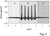
- Fig. 2 Such a time segmentation of a continuous measurement signal of a strain gauge is shown in Fig. 2 shown, three areas A, B, C can be seen. The segmentation is carried out in order to separate a load on the rail switch into an area A before, an area B during and an area C after an overflow of the rail vehicle via the sensor arranged on the rail switch.
- the time segmentation can additionally or alternatively be used for separating overflow signals from a locomotive and wagons and for separate analysis of individual axles.
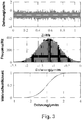
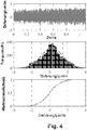
- Fig. 3 and 4th each show recorded and evaluated data of a rail vehicle crossing of a switch heart.
- the uppermost part shows the data recorded by the sensor before a sensor overflow, whereby an expansion is recorded per unit of time.
- a histogram of the acquired signal is shown as a strain-dependent frequency.
- the Kolmogorow-Smirnow test Such an evaluation distinguishes random noise, which is caused by conventional sources, from noise or disturbances, which are caused by an approaching rail vehicle. Noise caused by natural sources usually has a Gaussian distribution. Another statistical distribution points to other causes, for example to a faulty rail vehicle itself, a misshapen wheel of the same, a worn switch heart or other influences.
- Fig. 3 shows a Gaussian distribution
- Fig. 4 shows a different distribution and the data have oscillating components. This allows the conclusion that the in the Fig. 4 recorded and evaluated data represent a deviation from a normal state. In this case, individual flat spots in wheels, which are caused, for example, by braking not conforming to the standards and which lead to non-circular running behavior, can be identified. In the case of rail vehicles which have a Gaussian distribution in the lead, overflow signals can also be used for condition monitoring of the switch.
- Fig. 5 shows recorded data for six rail vehicles running without restrictions when traveling over a rail switch.
- Data from such rail vehicles have a Gaussian distribution in the lead.
- This example is a passenger train traveling at regular intervals via a rail switch instrumented with a sensor.
- locomotives of freight trains can also be compared, since similar rail vehicles also pass a rail switch at regular intervals. It is possible to couple the strain measurement with information about a type of rail vehicle. However, a clear identification of different rail vehicles is also possible without such additional information.
- Fig. 5 The raw data of a time-stretching signal measurement shown can be corrected with respect to an actual speed of the rail vehicle via a standard axis spacing and then made to coincide.
- Fig. 6 This enables a direct comparison of time-expansion curves of the rail vehicles traveling over the rail switch at different times.
- a rail network hereinavy load network, passenger train network or mixed traffic network
- Desired envelopes for each type of rail vehicle are obtained by using static methods, from which a state of a guideway component is subsequently determined and predicted.
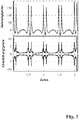
- Fig. 7 shows one from the in 5 and 6 Overflows of the same rail vehicle shown on different days of a week, as well as a deviation of individual measurements from the same. In this way, each new crossing of the same type of rail vehicle can be compared with the previous ones. Long-term monitoring of a form of the envelope curve thus allows direct conclusions to be drawn about a state of a Guideway component. Furthermore, continuous changes are recognized via the envelope curve.
- a continuous change in the envelope curve of a specific rail switch indicates normal wear, for example, while a sudden change in the envelope curve indicates breakouts in the area of a wheel transition. It is expedient to combine the different changes in envelopes with computer simulations of a wheel overflow for a specific switch type and a selected type of rail vehicle in order to improve a correlation between a measured change in the envelopes and a physical change in the route component. Since such computer simulations are very complex, it is expedient to create the results of a computer simulation in advance, for example on an influence of a wear-related change in the geometry of a route on a shape of the envelope curve. During operation, measured envelopes can then be compared on site with calculated curves. In this way, an assessment of a change in state is possible in real time. Subsequently, this also enables a prediction of the development of the condition of a rail switch.
Landscapes
- Engineering & Computer Science (AREA)
- Mechanical Engineering (AREA)
- Architecture (AREA)
- Civil Engineering (AREA)
- Structural Engineering (AREA)
- Automation & Control Theory (AREA)
- Machines For Laying And Maintaining Railways (AREA)
- Train Traffic Observation, Control, And Security (AREA)
- Length Measuring Devices With Unspecified Measuring Means (AREA)
- Electric Propulsion And Braking For Vehicles (AREA)
Claims (11)
- Procédé pour la surveillance d'état, en particulier en continu, d'au moins un composant de voie posé dans le domaine de la construction de voies ferrées, en particulier d'un aiguillage, avec au moins un capteur disposé au niveau du composant de voie, dans lequel des données sont détectées par le capteur pendant, et additionnellement avant et/ou après, un passage d'un véhicule ferroviaire sur le composant de voie, caractérisé en ce que les données détectées sont segmentées dans le temps, un état du composant de voie étant déterminé à partir des données détectées et segmentées.
- Procédé selon la revendication 1, caractérisé en ce que les données détectées et segmentées dans le temps sont analysées avec des méthodes statistiques et/ou des enveloppantes.
- Procédé selon la revendication 1 ou 2, caractérisé en ce que les données sont séparées dans le temps.
- Procédé selon l'une des revendications 1 à 3, caractérisé en ce que les données détectées sont traitées dans une unité de traitement de signaux reliée au capteur et disposée directement au niveau du composant de voie pour donner des informations sur un état du composant de voie.
- Procédé selon l'une des revendications 1 à 4, caractérisé en ce qu'à chaque passage d'un véhicule ferroviaire sur le composant de voie, des données sont détectées par l'au moins un capteur.
- Procédé selon l'une des revendications 1 à 5, caractérisé en ce que le capteur mesure au moins un allongement par unité de temps du composant de voie.
- Dispositif pour la surveillance d'état, en particulier en continu, d'au moins un composant de voie posé dans le domaine de la construction de voies ferrées, tel un aiguillage, comprenant au moins un capteur disposé au niveau du composant de voie, caractérisé en ce que le dispositif est réalisé pour la mise en œuvre d'un procédé selon l'une des revendications 1 à 6, dans lequel une unité de traitement de signaux est prévue pour analyser des données détectées par le capteur directement au niveau du composant de voie.
- Dispositif selon la revendication 7, caractérisé en ce que plusieurs capteurs sont disposés au niveau d'un composant de voie, dans lequel les capteurs sont de préférence réalisés pour la mesure de différentes données et sont reliés à l'unité de traitement de signaux.
- Dispositif selon la revendication 7 ou 8, caractérisé en ce qu'au niveau de plusieurs composants de voie sont disposés respectivement un ou plusieurs capteur(s) ainsi que respectivement une unité de traitement de signaux.
- Dispositif selon la revendication 9, caractérisé en ce que les unités de traitement de signaux sont reliées entre elles pour échanger des données détectées et/ou analysées.
- Dispositif selon l'une des revendications 7 à 10, caractérisé en ce que l'unité de traitement de signaux comprend un dispositif pour l'alimentation en énergie autosuffisante.
Applications Claiming Priority (2)
| Application Number | Priority Date | Filing Date | Title |
|---|---|---|---|
| ATA50458/2016A AT518759A1 (de) | 2016-05-17 | 2016-05-17 | Verfahren und Vorrichtung zur Überwachung zumindest einer im Bahnbau verlegten Fahrwegkomponente |
| PCT/AT2017/060129 WO2017197423A1 (fr) | 2016-05-17 | 2017-05-16 | Procédé et dispositif de surveillance d'au moins un composant de voie posé dans la construction de chemin de fer |
Publications (2)
| Publication Number | Publication Date |
|---|---|
| EP3458331A1 EP3458331A1 (fr) | 2019-03-27 |
| EP3458331B1 true EP3458331B1 (fr) | 2020-07-15 |
Family
ID=58744918
Family Applications (1)
| Application Number | Title | Priority Date | Filing Date |
|---|---|---|---|
| EP17724725.1A Active EP3458331B1 (fr) | 2016-05-17 | 2017-05-16 | Procédé et dispositif de surveillance d'au moins un composant de voie posé dans la construction de chemin de fer |
Country Status (4)
| Country | Link |
|---|---|
| EP (1) | EP3458331B1 (fr) |
| AT (1) | AT518759A1 (fr) |
| ES (1) | ES2823163T3 (fr) |
| WO (1) | WO2017197423A1 (fr) |
Families Citing this family (5)
| Publication number | Priority date | Publication date | Assignee | Title |
|---|---|---|---|---|
| US11260888B2 (en) * | 2018-11-16 | 2022-03-01 | Alstom Transport Technologies | Method and system for health assessment of a track circuit and/or of a track section |
| DE102019211406A1 (de) * | 2019-07-31 | 2021-02-04 | Siemens Mobility GmbH | Verfahren zum Erkennen fehlerhafter Messereignisse und Computerprogrammprodukt |
| ES3016588T3 (en) | 2020-06-16 | 2025-05-09 | Sensonic Gmbh | Method for monitoring a railway track and monitoring system for monitoring a railway track |
| EP4342764A1 (fr) | 2022-09-20 | 2024-03-27 | voestalpine Signaling Austria GmbH | Procédé de surveillance d'un aiguillage de rails et entraînement d'aiguillage |
| EP4628387A1 (fr) | 2024-04-04 | 2025-10-08 | voestalpine Signaling Austria GmbH | Procédé et dispositif de localisation d'au moins une irrégularité d'un contact de voie de roulement de roue |
Family Cites Families (5)
| Publication number | Priority date | Publication date | Assignee | Title |
|---|---|---|---|---|
| DE4207516A1 (de) * | 1992-03-10 | 1993-09-16 | Gerd R Dipl Ing Wetzler | Verfahren zur erzeugung belastungsabhaengiger schaltsignale an eisenbahnschienen |
| DE102007034504A1 (de) * | 2007-07-24 | 2009-02-05 | Rögener, Baldur | Verfahren und Überwachungssystem zum Überwachen von Schienen-Fahrwegen |
| DE202010009904U1 (de) * | 2010-06-24 | 2011-10-25 | Baldur Rögener | Messtechnische Anordnung zur Bestimmung der Gleislage und/oder Änderung der Gleisgeometrie (Deformation) |
| DE102011084160A1 (de) * | 2011-10-07 | 2013-04-11 | Siemens Aktiengesellschaft | Verfahren und Vorrichtung zur Schienenbrucherkennung |
| DE102014216726A1 (de) * | 2014-08-22 | 2016-02-25 | Siemens Aktiengesellschaft | Verfahren zur Erhöhung der Verfügbarkeit einer Raderkennungseinrichtung und Raderkennungseinrichtung |
-
2016
- 2016-05-17 AT ATA50458/2016A patent/AT518759A1/de unknown
-
2017
- 2017-05-16 ES ES17724725T patent/ES2823163T3/es active Active
- 2017-05-16 WO PCT/AT2017/060129 patent/WO2017197423A1/fr not_active Ceased
- 2017-05-16 EP EP17724725.1A patent/EP3458331B1/fr active Active
Non-Patent Citations (1)
| Title |
|---|
| None * |
Also Published As
| Publication number | Publication date |
|---|---|
| ES2823163T3 (es) | 2021-05-06 |
| EP3458331A1 (fr) | 2019-03-27 |
| WO2017197423A1 (fr) | 2017-11-23 |
| AT518759A1 (de) | 2017-12-15 |
Similar Documents
| Publication | Publication Date | Title |
|---|---|---|
| EP3458331B1 (fr) | Procédé et dispositif de surveillance d'au moins un composant de voie posé dans la construction de chemin de fer | |
| DE102004045457B4 (de) | Verfahren zur Diagnose und zum Zustandsmonitoring von Weichen, Kreuzungen oder Kreuzungsweichen sowie Schienenstößen durch ein Schienenfahrzeug | |
| EP2212180B1 (fr) | Détermination de la durée de vie résiduelle d'un élément de véhicule | |
| EP3665048B1 (fr) | Procédé et dispositif pour déterminer des modifications dans le comportement de dynamique longitudinale d'un véhicule ferroviaire | |
| EP2359104B1 (fr) | Système pour l'analyse de l'état de l'organe de roulement de véhicules ferroviaires | |
| EP3206933B1 (fr) | Diagnostic de l'état des roues d'un véhicule ferroviaire | |
| DE102020121485B3 (de) | Verfahren zur Feststellung und Bewertung von Störungen im Fahrzeug-Fahrweg-System innerhalb des Eisenbahn-Regelbetriebs | |
| WO2018041569A1 (fr) | Dispositif et procédé pour déterminer l'état de voies ferrées | |
| EP2464556B1 (fr) | Procédé et dispositif électronique pour surveiller l'état de composants dans des véhicules ferroviaires | |
| DE19836081A1 (de) | Verfahren zur Früherkennung von Schäden an Schienenfahrzeugen | |
| DE19837476A1 (de) | Verfahren zum vorbeugenden Überwachen des Fahrverhaltens von Schienenfahrzeugen | |
| EP3584199A1 (fr) | Procédé et système pour la détection de l'usure pendant le fonctionnement d'un système de convoyeur | |
| EP2956348B1 (fr) | Surveillance d'éléments d'attelage d'un véhicule | |
| EP3053804A2 (fr) | Procede et dispositif d'optimisation d'un entretien de superstructure de voie par classification individuelle de defaut | |
| WO2018104040A1 (fr) | Procédé et dispositif destinés au diagnostic d'un aiguillage sous charge | |
| DE10062602B4 (de) | Verfahren und Vorrichtung zum Überwachen des Fahrverhaltens von Schienenfahrzeugen und zur Diagnose von Komponenten von Schienenfahrzeugen | |
| EP3601010B1 (fr) | Contrôle de l'état d'un élément d'usure | |
| WO2025210201A1 (fr) | Procédé de localisation d'au moins une discontinuité d'un contact roue-voie | |
| DE102008008578B3 (de) | Ermittlung der dynamischen Radkraft eines Eisenbahnfahrzeugs auf das Herzstück einer Weiche | |
| DE10020520A1 (de) | Verfahren und Vorrichtung zum Überwachen von Fahreigenschaften eines Schienenfahrzeuges | |
| WO2000051868A1 (fr) | Procede et dispositif pour surveiller un vehicule | |
| DE102009015011A1 (de) | Verfahren zur Überwachung der Laufstabilität bei Schienenfahrzeugen | |
| EP3823876B1 (fr) | Procédé et système de reconnaissance d'une roue de véhicule ferroviaire | |
| EP3560792B1 (fr) | Procédé de commande d'une installation de sécurité ferroviaire | |
| EP3507166A1 (fr) | Procédé et dispositif permettant de surveiller des états de véhicules ferroviaires |
Legal Events
| Date | Code | Title | Description |
|---|---|---|---|
| STAA | Information on the status of an ep patent application or granted ep patent |
Free format text: STATUS: UNKNOWN |
|
| STAA | Information on the status of an ep patent application or granted ep patent |
Free format text: STATUS: THE INTERNATIONAL PUBLICATION HAS BEEN MADE |
|
| PUAI | Public reference made under article 153(3) epc to a published international application that has entered the european phase |
Free format text: ORIGINAL CODE: 0009012 |
|
| STAA | Information on the status of an ep patent application or granted ep patent |
Free format text: STATUS: REQUEST FOR EXAMINATION WAS MADE |
|
| 17P | Request for examination filed |
Effective date: 20181214 |
|
| AK | Designated contracting states |
Kind code of ref document: A1 Designated state(s): AL AT BE BG CH CY CZ DE DK EE ES FI FR GB GR HR HU IE IS IT LI LT LU LV MC MK MT NL NO PL PT RO RS SE SI SK SM TR |
|
| AX | Request for extension of the european patent |
Extension state: BA ME |
|
| DAV | Request for validation of the european patent (deleted) | ||
| DAX | Request for extension of the european patent (deleted) | ||
| STAA | Information on the status of an ep patent application or granted ep patent |
Free format text: STATUS: EXAMINATION IS IN PROGRESS |
|
| 17Q | First examination report despatched |
Effective date: 20191209 |
|
| GRAP | Despatch of communication of intention to grant a patent |
Free format text: ORIGINAL CODE: EPIDOSNIGR1 |
|
| STAA | Information on the status of an ep patent application or granted ep patent |
Free format text: STATUS: GRANT OF PATENT IS INTENDED |
|
| INTG | Intention to grant announced |
Effective date: 20200506 |
|
| GRAS | Grant fee paid |
Free format text: ORIGINAL CODE: EPIDOSNIGR3 |
|
| GRAA | (expected) grant |
Free format text: ORIGINAL CODE: 0009210 |
|
| STAA | Information on the status of an ep patent application or granted ep patent |
Free format text: STATUS: THE PATENT HAS BEEN GRANTED |
|
| AK | Designated contracting states |
Kind code of ref document: B1 Designated state(s): AL AT BE BG CH CY CZ DE DK EE ES FI FR GB GR HR HU IE IS IT LI LT LU LV MC MK MT NL NO PL PT RO RS SE SI SK SM TR |
|
| REG | Reference to a national code |
Ref country code: CH Ref legal event code: EP Ref country code: GB Ref legal event code: FG4D Free format text: NOT ENGLISH |
|
| REG | Reference to a national code |
Ref country code: DE Ref legal event code: R096 Ref document number: 502017006220 Country of ref document: DE |
|
| REG | Reference to a national code |
Ref country code: IE Ref legal event code: FG4D Free format text: LANGUAGE OF EP DOCUMENT: GERMAN |
|
| REG | Reference to a national code |
Ref country code: AT Ref legal event code: REF Ref document number: 1290720 Country of ref document: AT Kind code of ref document: T Effective date: 20200815 |
|
| REG | Reference to a national code |
Ref country code: CH Ref legal event code: NV Representative=s name: INDUSTRIAL PROPERTY SERVICES GMBH, CH |
|
| REG | Reference to a national code |
Ref country code: NL Ref legal event code: FP |
|
| REG | Reference to a national code |
Ref country code: SE Ref legal event code: TRGR |
|
| REG | Reference to a national code |
Ref country code: LT Ref legal event code: MG4D |
|
| PG25 | Lapsed in a contracting state [announced via postgrant information from national office to epo] |
Ref country code: FI Free format text: LAPSE BECAUSE OF FAILURE TO SUBMIT A TRANSLATION OF THE DESCRIPTION OR TO PAY THE FEE WITHIN THE PRESCRIBED TIME-LIMIT Effective date: 20200715 Ref country code: LT Free format text: LAPSE BECAUSE OF FAILURE TO SUBMIT A TRANSLATION OF THE DESCRIPTION OR TO PAY THE FEE WITHIN THE PRESCRIBED TIME-LIMIT Effective date: 20200715 Ref country code: PT Free format text: LAPSE BECAUSE OF FAILURE TO SUBMIT A TRANSLATION OF THE DESCRIPTION OR TO PAY THE FEE WITHIN THE PRESCRIBED TIME-LIMIT Effective date: 20201116 Ref country code: BG Free format text: LAPSE BECAUSE OF FAILURE TO SUBMIT A TRANSLATION OF THE DESCRIPTION OR TO PAY THE FEE WITHIN THE PRESCRIBED TIME-LIMIT Effective date: 20201015 Ref country code: NO Free format text: LAPSE BECAUSE OF FAILURE TO SUBMIT A TRANSLATION OF THE DESCRIPTION OR TO PAY THE FEE WITHIN THE PRESCRIBED TIME-LIMIT Effective date: 20201015 Ref country code: GR Free format text: LAPSE BECAUSE OF FAILURE TO SUBMIT A TRANSLATION OF THE DESCRIPTION OR TO PAY THE FEE WITHIN THE PRESCRIBED TIME-LIMIT Effective date: 20201016 Ref country code: HR Free format text: LAPSE BECAUSE OF FAILURE TO SUBMIT A TRANSLATION OF THE DESCRIPTION OR TO PAY THE FEE WITHIN THE PRESCRIBED TIME-LIMIT Effective date: 20200715 |
|
| PG25 | Lapsed in a contracting state [announced via postgrant information from national office to epo] |
Ref country code: RS Free format text: LAPSE BECAUSE OF FAILURE TO SUBMIT A TRANSLATION OF THE DESCRIPTION OR TO PAY THE FEE WITHIN THE PRESCRIBED TIME-LIMIT Effective date: 20200715 Ref country code: PL Free format text: LAPSE BECAUSE OF FAILURE TO SUBMIT A TRANSLATION OF THE DESCRIPTION OR TO PAY THE FEE WITHIN THE PRESCRIBED TIME-LIMIT Effective date: 20200715 Ref country code: LV Free format text: LAPSE BECAUSE OF FAILURE TO SUBMIT A TRANSLATION OF THE DESCRIPTION OR TO PAY THE FEE WITHIN THE PRESCRIBED TIME-LIMIT Effective date: 20200715 Ref country code: IS Free format text: LAPSE BECAUSE OF FAILURE TO SUBMIT A TRANSLATION OF THE DESCRIPTION OR TO PAY THE FEE WITHIN THE PRESCRIBED TIME-LIMIT Effective date: 20201115 |
|
| REG | Reference to a national code |
Ref country code: DE Ref legal event code: R097 Ref document number: 502017006220 Country of ref document: DE |
|
| PG25 | Lapsed in a contracting state [announced via postgrant information from national office to epo] |
Ref country code: DK Free format text: LAPSE BECAUSE OF FAILURE TO SUBMIT A TRANSLATION OF THE DESCRIPTION OR TO PAY THE FEE WITHIN THE PRESCRIBED TIME-LIMIT Effective date: 20200715 Ref country code: CZ Free format text: LAPSE BECAUSE OF FAILURE TO SUBMIT A TRANSLATION OF THE DESCRIPTION OR TO PAY THE FEE WITHIN THE PRESCRIBED TIME-LIMIT Effective date: 20200715 Ref country code: RO Free format text: LAPSE BECAUSE OF FAILURE TO SUBMIT A TRANSLATION OF THE DESCRIPTION OR TO PAY THE FEE WITHIN THE PRESCRIBED TIME-LIMIT Effective date: 20200715 Ref country code: EE Free format text: LAPSE BECAUSE OF FAILURE TO SUBMIT A TRANSLATION OF THE DESCRIPTION OR TO PAY THE FEE WITHIN THE PRESCRIBED TIME-LIMIT Effective date: 20200715 Ref country code: SM Free format text: LAPSE BECAUSE OF FAILURE TO SUBMIT A TRANSLATION OF THE DESCRIPTION OR TO PAY THE FEE WITHIN THE PRESCRIBED TIME-LIMIT Effective date: 20200715 |
|
| REG | Reference to a national code |
Ref country code: ES Ref legal event code: FG2A Ref document number: 2823163 Country of ref document: ES Kind code of ref document: T3 Effective date: 20210506 |
|
| PLBE | No opposition filed within time limit |
Free format text: ORIGINAL CODE: 0009261 |
|
| STAA | Information on the status of an ep patent application or granted ep patent |
Free format text: STATUS: NO OPPOSITION FILED WITHIN TIME LIMIT |
|
| PG25 | Lapsed in a contracting state [announced via postgrant information from national office to epo] |
Ref country code: AL Free format text: LAPSE BECAUSE OF FAILURE TO SUBMIT A TRANSLATION OF THE DESCRIPTION OR TO PAY THE FEE WITHIN THE PRESCRIBED TIME-LIMIT Effective date: 20200715 |
|
| 26N | No opposition filed |
Effective date: 20210416 |
|
| PG25 | Lapsed in a contracting state [announced via postgrant information from national office to epo] |
Ref country code: SK Free format text: LAPSE BECAUSE OF FAILURE TO SUBMIT A TRANSLATION OF THE DESCRIPTION OR TO PAY THE FEE WITHIN THE PRESCRIBED TIME-LIMIT Effective date: 20200715 |
|
| PG25 | Lapsed in a contracting state [announced via postgrant information from national office to epo] |
Ref country code: SI Free format text: LAPSE BECAUSE OF FAILURE TO SUBMIT A TRANSLATION OF THE DESCRIPTION OR TO PAY THE FEE WITHIN THE PRESCRIBED TIME-LIMIT Effective date: 20200715 |
|
| PG25 | Lapsed in a contracting state [announced via postgrant information from national office to epo] |
Ref country code: LU Free format text: LAPSE BECAUSE OF NON-PAYMENT OF DUE FEES Effective date: 20210516 Ref country code: MC Free format text: LAPSE BECAUSE OF FAILURE TO SUBMIT A TRANSLATION OF THE DESCRIPTION OR TO PAY THE FEE WITHIN THE PRESCRIBED TIME-LIMIT Effective date: 20200715 |
|
| PG25 | Lapsed in a contracting state [announced via postgrant information from national office to epo] |
Ref country code: IE Free format text: LAPSE BECAUSE OF NON-PAYMENT OF DUE FEES Effective date: 20210516 |
|
| PG25 | Lapsed in a contracting state [announced via postgrant information from national office to epo] |
Ref country code: CY Free format text: LAPSE BECAUSE OF FAILURE TO SUBMIT A TRANSLATION OF THE DESCRIPTION OR TO PAY THE FEE WITHIN THE PRESCRIBED TIME-LIMIT Effective date: 20200715 |
|
| P01 | Opt-out of the competence of the unified patent court (upc) registered |
Effective date: 20230527 |
|
| PG25 | Lapsed in a contracting state [announced via postgrant information from national office to epo] |
Ref country code: HU Free format text: LAPSE BECAUSE OF FAILURE TO SUBMIT A TRANSLATION OF THE DESCRIPTION OR TO PAY THE FEE WITHIN THE PRESCRIBED TIME-LIMIT; INVALID AB INITIO Effective date: 20170516 |
|
| PG25 | Lapsed in a contracting state [announced via postgrant information from national office to epo] |
Ref country code: MK Free format text: LAPSE BECAUSE OF FAILURE TO SUBMIT A TRANSLATION OF THE DESCRIPTION OR TO PAY THE FEE WITHIN THE PRESCRIBED TIME-LIMIT Effective date: 20200715 |
|
| REG | Reference to a national code |
Ref country code: NL Ref legal event code: PD Owner name: VOESTALPINE SIGNALING AUSTRIA GMBH; AT Free format text: DETAILS ASSIGNMENT: CHANGE OF OWNER(S), ASSIGNMENT; FORMER OWNER NAME: MATERIALS CENTER LEOBEN FORSCHUNG GMBH Effective date: 20240712 |
|
| REG | Reference to a national code |
Ref country code: DE Ref legal event code: R081 Ref document number: 502017006220 Country of ref document: DE Owner name: VOESTALPINE SIGNALING AUSTRIA GMBH, AT Free format text: FORMER OWNER: MATERIALS CENTER LEOBEN FORSCHUNG GMBH, LEOBEN, AT |
|
| REG | Reference to a national code |
Ref country code: GB Ref legal event code: 732E Free format text: REGISTERED BETWEEN 20240711 AND 20240717 |
|
| REG | Reference to a national code |
Ref country code: BE Ref legal event code: PD Owner name: VOESTALPINE SIGNALING AUSTRIA; AT Free format text: DETAILS ASSIGNMENT: CHANGE OF OWNER(S), ASSIGNMENT; FORMER OWNER NAME: MATERIALS CENTER LEOBEN FORSCHUNG GMBH Effective date: 20240705 |
|
| REG | Reference to a national code |
Ref country code: AT Ref legal event code: PC Ref document number: 1290720 Country of ref document: AT Kind code of ref document: T Owner name: VOESTALPINE SIGNALING AUSTRIA GMBH, AT Effective date: 20240809 |
|
| PG25 | Lapsed in a contracting state [announced via postgrant information from national office to epo] |
Ref country code: MT Free format text: LAPSE BECAUSE OF FAILURE TO SUBMIT A TRANSLATION OF THE DESCRIPTION OR TO PAY THE FEE WITHIN THE PRESCRIBED TIME-LIMIT Effective date: 20200715 |
|
| REG | Reference to a national code |
Ref country code: ES Ref legal event code: PC2A Owner name: VOESTALPINE SIGNALING AUSTRIA GMBH Effective date: 20241104 |
|
| PGFP | Annual fee paid to national office [announced via postgrant information from national office to epo] |
Ref country code: NL Payment date: 20250521 Year of fee payment: 9 |
|
| PGFP | Annual fee paid to national office [announced via postgrant information from national office to epo] |
Ref country code: DE Payment date: 20250521 Year of fee payment: 9 |
|
| PGFP | Annual fee paid to national office [announced via postgrant information from national office to epo] |
Ref country code: GB Payment date: 20250527 Year of fee payment: 9 |
|
| PGFP | Annual fee paid to national office [announced via postgrant information from national office to epo] |
Ref country code: BE Payment date: 20250521 Year of fee payment: 9 Ref country code: IT Payment date: 20250527 Year of fee payment: 9 |
|
| PGFP | Annual fee paid to national office [announced via postgrant information from national office to epo] |
Ref country code: FR Payment date: 20250528 Year of fee payment: 9 |
|
| PGFP | Annual fee paid to national office [announced via postgrant information from national office to epo] |
Ref country code: CH Payment date: 20250601 Year of fee payment: 9 |
|
| PGFP | Annual fee paid to national office [announced via postgrant information from national office to epo] |
Ref country code: AT Payment date: 20250522 Year of fee payment: 9 |
|
| PGFP | Annual fee paid to national office [announced via postgrant information from national office to epo] |
Ref country code: SE Payment date: 20250521 Year of fee payment: 9 |
|
| PGFP | Annual fee paid to national office [announced via postgrant information from national office to epo] |
Ref country code: ES Payment date: 20250630 Year of fee payment: 9 |
|
| PG25 | Lapsed in a contracting state [announced via postgrant information from national office to epo] |
Ref country code: TR Free format text: LAPSE BECAUSE OF FAILURE TO SUBMIT A TRANSLATION OF THE DESCRIPTION OR TO PAY THE FEE WITHIN THE PRESCRIBED TIME-LIMIT Effective date: 20200715 |