EP3458660B1 - Türschliessmechanismus mit einer im türrahmen eingelassenen aufnahme für den schliessriegel einer in die tür eingelassenen vorrichtung zum steuern des schliessriegels in die öffnungsstellung mittels eines manuell steuerbaren betätigungsglieds - Google Patents
Türschliessmechanismus mit einer im türrahmen eingelassenen aufnahme für den schliessriegel einer in die tür eingelassenen vorrichtung zum steuern des schliessriegels in die öffnungsstellung mittels eines manuell steuerbaren betätigungsglieds Download PDFInfo
- Publication number
- EP3458660B1 EP3458660B1 EP16729198.8A EP16729198A EP3458660B1 EP 3458660 B1 EP3458660 B1 EP 3458660B1 EP 16729198 A EP16729198 A EP 16729198A EP 3458660 B1 EP3458660 B1 EP 3458660B1
- Authority
- EP
- European Patent Office
- Prior art keywords
- door
- locking bolt
- slide
- handle
- frame
- Prior art date
- Legal status (The legal status is an assumption and is not a legal conclusion. Google has not performed a legal analysis and makes no representation as to the accuracy of the status listed.)
- Active
Links
Images




Classifications
-
- E—FIXED CONSTRUCTIONS
- E05—LOCKS; KEYS; WINDOW OR DOOR FITTINGS; SAFES
- E05C—BOLTS OR FASTENING DEVICES FOR WINGS, SPECIALLY FOR DOORS OR WINDOWS
- E05C1/00—Fastening devices with bolts moving rectilinearly
- E05C1/08—Fastening devices with bolts moving rectilinearly with latching action
- E05C1/12—Fastening devices with bolts moving rectilinearly with latching action with operating handle or equivalent member moving otherwise than rigidly with the latch
- E05C1/14—Fastening devices with bolts moving rectilinearly with latching action with operating handle or equivalent member moving otherwise than rigidly with the latch the handle or member moving essentially towards or away from the plane of the wing or frame
- E05C1/145—Fastening devices with bolts moving rectilinearly with latching action with operating handle or equivalent member moving otherwise than rigidly with the latch the handle or member moving essentially towards or away from the plane of the wing or frame flush
-
- E—FIXED CONSTRUCTIONS
- E05—LOCKS; KEYS; WINDOW OR DOOR FITTINGS; SAFES
- E05C—BOLTS OR FASTENING DEVICES FOR WINGS, SPECIALLY FOR DOORS OR WINDOWS
- E05C1/00—Fastening devices with bolts moving rectilinearly
- E05C1/02—Fastening devices with bolts moving rectilinearly without latching action
- E05C1/06—Fastening devices with bolts moving rectilinearly without latching action with operating handle or equivalent member moving otherwise than rigidly with the bolt
- E05C1/065—Fastening devices with bolts moving rectilinearly without latching action with operating handle or equivalent member moving otherwise than rigidly with the bolt flush
-
- E—FIXED CONSTRUCTIONS
- E05—LOCKS; KEYS; WINDOW OR DOOR FITTINGS; SAFES
- E05B—LOCKS; ACCESSORIES THEREFOR; HANDCUFFS
- E05B47/00—Operating or controlling locks or other fastening devices by electric or magnetic means
- E05B47/0038—Operating or controlling locks or other fastening devices by electric or magnetic means using permanent magnets
-
- E—FIXED CONSTRUCTIONS
- E05—LOCKS; KEYS; WINDOW OR DOOR FITTINGS; SAFES
- E05B—LOCKS; ACCESSORIES THEREFOR; HANDCUFFS
- E05B5/00—Handles completely let into the surface of the wing
-
- E—FIXED CONSTRUCTIONS
- E05—LOCKS; KEYS; WINDOW OR DOOR FITTINGS; SAFES
- E05B—LOCKS; ACCESSORIES THEREFOR; HANDCUFFS
- E05B63/00—Locks or fastenings with special structural characteristics
- E05B63/0056—Locks with adjustable or exchangeable lock parts
-
- E—FIXED CONSTRUCTIONS
- E05—LOCKS; KEYS; WINDOW OR DOOR FITTINGS; SAFES
- E05B—LOCKS; ACCESSORIES THEREFOR; HANDCUFFS
- E05B63/00—Locks or fastenings with special structural characteristics
- E05B63/04—Locks or fastenings with special structural characteristics for alternative use on the right-hand or left-hand side of wings
-
- E—FIXED CONSTRUCTIONS
- E05—LOCKS; KEYS; WINDOW OR DOOR FITTINGS; SAFES
- E05Y—INDEXING SCHEME ASSOCIATED WITH SUBCLASSES E05D AND E05F, RELATING TO CONSTRUCTION ELEMENTS, ELECTRIC CONTROL, POWER SUPPLY, POWER SIGNAL OR TRANSMISSION, USER INTERFACES, MOUNTING OR COUPLING, DETAILS, ACCESSORIES, AUXILIARY OPERATIONS NOT OTHERWISE PROVIDED FOR, APPLICATION THEREOF
- E05Y2900/00—Application of doors, windows, wings or fittings thereof
- E05Y2900/10—Application of doors, windows, wings or fittings thereof for buildings or parts thereof
- E05Y2900/13—Type of wing
- E05Y2900/132—Doors
Definitions
- the invention relates to a door locking mechanism with a recess in the door frame for a locking bolt of a device recessed in the door for controlling the locking bolt into the open position by means of a manually controllable actuator.
- a door closing mechanism accommodated in a housing is known according to the preamble of claim 1, in which an actuating element designed as a grip shell, to which a first lever is formed, which moves a second lever via a slide, actuated an associated spring-loaded locking bolt.
- the JP 2009 197 538 A shows another door locking mechanism not housed in a housing, in which a handle designed as a first lever moves a second lever via a slide, which actuates a spring-loaded locking bolt.
- the US 2015 001 859 A1 again shows a door locking mechanism housed in a housing with a handle shell of a first device which can be lowered into a door and which is connected to a first lever which actuates a second lever of a second device which can be connected to it and which moves the locking bar of the second device from a locking to a locking device Open position moved.
- the actuator of the device let into the door is designed as a shell handle that controls a slide in the closed position via a mounted control angle, the slide holding the locking bolt in the receptacle of the door frame via a rotatably mounted lever, and that when Actuation of the handle in the door can be adjusted to the opening position of the door using the control angle and the slide of the locking bolt and the door is released for opening.
- the door closing mechanism When the handle shell is not actuated, the door closing mechanism is always fixed in its closed position and can be brought into the open position and the door opened by actuating the handle shell, the latter requiring no additional means in the door closing mechanism.
- a door closing mechanism is particularly suitable for a toilet door, which also allows the opening position of the door to be set in a simple manner.
- the handle shell is preferably embedded flush in a frame of the device in the door and can be folded out of the frame in such a way that it adjusts the control angle, the slide and the lever in such a way that the locking bolt completely leaves the receptacle in the door frame.
- the device with the tray handle can be installed in the door in such a way that it takes up four different positions, each at 90 ° to one another are rotated, the shell handle being foldable either downwards, to the left, upwards or to the right out of the frame connected to the door. In this way, the structure can always be adapted to the most favorable operating position.
- the shell handle extends to a handle opening over the frame, making it easier to grip the shell handle to operate the door locking mechanism.
- the shell handle is coupled to the head angle in such a way that when the shell handle is folded out, the control lever rotates and the slide can be adjusted parallel to the locking bolt, the adjustable slide twisting the lever so far and the slide parallel to the locking bolt that the locking bolt can be adjusted Has completely left the holder in the door frame.
- the locking bolt is guided in a plate that can be connected to the front of the door.
- This plate is connected to a perpendicular plate, which carries bearing bolts for the rotary mounting of the lever and the adjustment of the slide, the lever being rotatably mounted on the bearing bolt and the slide provided with guide receptacles being displaceable on the bearing bolt.
- the lever, the slide and the locking bolt are covered with a plate parallel to the plate with the bearing bolts.
- the head angle is rotatably mounted in the frame around the handle.
- the locking bolt can also carry one or more permanent magnets.
- the control angle which is made of electromagnetically conductive material, can be adjusted in the area of these permanent magnets when the handle is actuated.
- the locking bolt is adjusted in the open position, and a spring returns the locking bolt in the closed position of the handle shell in its closed position in the receptacle in the door frame.
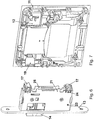
- the Fig. 1 shows a section of a door 10, in which a frame 11 is inserted with an upwardly open handle 12. In the closed position, the locking bolt 14 protrudes on the vertical end face of the door 10. This locking bolt 14 is guided in a plate 13 which is connected to the end face of the door 10. The plate 13 is flush with the front of the door 10.
- the Fig. 2 shows the two components of the device, which are embedded in the door 10 from the rear.
- the components are covered with a plate 21.
- a slide 17 projects, to which a control angle 19 is assigned.
- the rear of the frame 11 is provided with the control bracket 19 and the handle shell 12 such that when the handle shell 12 is actuated, the control bracket 19 is rotated and the slide 17 is adjusted parallel to the locking bolt 14.
- the lever 15 is rotated about the bearing pin 16 when the slide 17 is adjusted.
- the locking bolt 14 is retracted on the bearing pin 22 and moved completely out of the receptacle in the door frame (not shown).
- the door closing mechanism assumes its open position and the door 10 can be opened.
- the slide 17 is provided in the area of the bearing bolts 23 and 24 with guide receptacles which allow the slide 17 to be adjusted parallel to the locking bolt 14.
- the plate 13 is connected to a perpendicular plate 25 which carries the bearing bolts 16, 23 and 24.
- the lever 15 is coupled to the slide 17 and the locking bolt 14, so that a rotation of the lever 15 leads to the locking bolt 14 being drawn in.
- the 4 and 5 show the two assemblies in the door 10 in separate drawings.
- the drawings show that a control angle 19 is assigned to the slide 17 and is rotatably arranged in the frame 11 of the grip shell 12.
- the control angle 19 executes its rotational movement when the grip shell 12 is folded out of the frame 11. This rotary movement is transmitted to the slide 17, which thereby causes the retraction movement and adjustment of the locking bolt 14 in the open position.
- the grip shell 12 can also be installed in the frame 11 so that the grip shell is open at the bottom.
- the control angle 19 is then assigned to a second slide 17 which is longitudinally adjustable on the plate 25 and rotates a lever 15 which causes the locking bolt 14 to be pulled in and the door closing mechanism to be set into the open position.
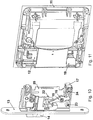
- Both 8 and 9 the grip shell 12 is installed in the frame 11 such that the grip shell 12 is open to the left.
- the control bracket 19, which is rotatably mounted in the frame 11, is designed with an extension 26 at the point facing the slide 17 as an adjustable part 19 and thereby initiates the retraction of the locking bolt 14 and thus the setting of the door locking mechanism into the open position.
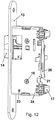
- Fig. 12 and 13 show the components in the door 10 in separate drawings and correspond to Fig. 2 .
Landscapes
- Engineering & Computer Science (AREA)
- Structural Engineering (AREA)
- Mechanical Engineering (AREA)
- Securing Of Glass Panes Or The Like (AREA)
- Closing And Opening Devices For Wings, And Checks For Wings (AREA)
- Wing Frames And Configurations (AREA)
- Lock And Its Accessories (AREA)
Description
- Die Erfindung betrifft einen Türschließmechanismus mit einer in den Türrahmen eingelassenen Aufnahme für einen Schließriegel einer in die Tür eingelassenen Vorrichtung zum Steuern des Schließriegels in die Öffnungsstellung mittels eines manuell steuerbaren Betätigungsglieds.
- Aus der
JP 2002 295 102 A - Die
JP 2009 197 538 A - Aus der
JP H05 118 173 A - Die
US 2015 001 859 A1 zeigt wiederum einen in einem Gehäuse untergebrachten Türschließmechanismus mit einer in eine Tür versenkbaren Griffschale einer ersten Vorrichtung, die mit einem ersten Hebel verbunden ist, der einen damit verbindbaren zweiten Hebel einer zweiten Vorrichtung betätigt, der den Schließriegel der zweiten Vorrichtung aus einer Schließ- in eine Öffnungsstellung bewegt. - Es sind weitere derartigere Türschließmechanismen bekannt, bei denen das manuell steuerbare Betätigungsglied als Türgriff ausgebildet ist. Beim Verdrehen des Türgriffs wird der Schließriegel aus der Aufnahme im Türrahmen herausgeführt, so dass die Tür geöffnet werden kann. Zum Absperren der Tür in der Schließstellung ist in den Türschließmechanismus ein mit einem Schlüssel absperrendes Schloss integriert. Dies macht den Türschließmechanismus kompliziert und verteuert seine Herstellung.
- Es ist Aufgabe der Erfindung, einen Türschließmechanismus der eingangs erwähnten Art so weiterzuentwickeln, dass seine Schließstellung ohne zusätzliches schlüsselbetätigtes Schloss in der Schließstellung arretiert und festgelegt ist, seine einfache Einstellung in die Öffnungsstellung aber dafür nicht erschwert wird. Ferner ist Aufgabe der Erfindung, den Aufbau stets an die günstigste Bedienungsstellung anpassen zu können.
- Die gestellte Aufgabe wird durch die Merkmale des Anspruchs 1 gelöst.
- Dies ist dadurch erreicht, dass das Betätigungsglied der in die Tür eingelassenen Vorrichtung als Schalengriff ausgebildet ist, der in der Schließstellung über einen gelagerten Steuerwinkel einen Schieber steuert, wobei der Schieber über einen drehbar gelagerten Hebel den Schließriegel in der Aufnahme des Türrahmens festhält und dass beim Betätigen der Griffschale in der Tür über den Steuerwinkel und den Schieber der Schließriegel in die Öffnungsstellung der Tür einstellbar und die Tür zum Öffnen freigegeben ist.
- Bei nicht betätigter Griffschale ist der Türschließmechanismus stets in seiner Schließstellung festgelegt und kann durch Betätigen der Griffschale in die Öffnungsstellung gebracht und die Tür geöffnet werden, wobei letzteres keine zusätzlichen Mittel in dem Türschließmechanismus erfordert. Ein derartiger Türschließmechanismus ist insbesondere für eine Toilettentür geeignet, die auf einfache Weise auch noch eine Einstellung der Öffnungsstellung der Tür ermöglicht.
- Die Griffschale ist vorzugsweise bündig in einen Rahmen der Vorrichtung in der Tür eingelassen und aus dem Rahmen so ausklappbar, dass sie dabei den Steuerwinkel, den Schieber und den Hebel so verstellt, dass der Schließriegel die Aufnahme im Türrahmen vollständig verlässt. Die Vorrichtung mit dem Schalengriff ist erfindungsgemäß so in die Tür einbaubar, dass sie vier verschiedene Stellungen einnimmt, die jeweils um 90° gegeneinander verdreht sind, wobei der Schalengriff entweder nach unten, nach links, nach oben oder nach rechts aus dem mit der Tür verbundenen Rahmen ausklappbar ist. Auf diese Weise kann der Aufbau stets an die günstigste Bedienungsstellung angepasst werden.
- Der Schalengriff erstreckt sich bis auf eine Grifföffnung über den Rahmen und erleichtert so das Fassen des Schalengriffs zum Betätigen des Türschließmechanismus.
- Der Schalengriff ist so mit dem Steuerwinkel gekoppelt, dass beim Ausklappen des Schalengriffs der Steuerhebel verdreht und der Schieber parallel zum Schließriegel verstellbar ist, wobei der verstellbare Schieber den Hebel so weit verdreht und der Schieber parallel zum Schließriegel so weit verstellbar ist, dass der Schließriegel die Aufnahme im Türrahmen vollständig verlassen hat.
- Der Schließriegel ist in einer mit der Stirnseite der Tür verbindbaren Platte geführt. Diese Platte ist mit einer senkrecht dazu stehenden Platte verbunden, die Lagerbolzen für die Drehlagerung des Hebels und die Verstellung des Schiebers trägt, wobei der Hebel auf dem Lagerbolzen drehbar gelagert und der Schieber mit Führungsaufnahmen versehen auf den Lagerbolzen verschiebbar ist.
- Der Hebel, der Schieber und der Schließriegel sind mit einer zur Platte mit den Lagerbolzen parallelen Platte abgedeckt.
- Der Steuerwinkel ist erfindungsgemäß im Rahmen um die Griffschale drehbar gelagert.
- In einer nicht erfindungsgemäßen Ausführungsform kann der Schließriegel auch einen oder mehrere Dauermagnete tragen. Der aus elektromagnetisch leitendem Material bestehende Steuerwinkel ist in den Bereich dieser Dauermagnete beim Betätigen der Griffschale verstellbar. Der Schließriegel ist dabei in die Öffnungsstellung verstellt, und eine Feder stellt den Schließriegel in der Schließstellung der Griffschale in seine Schließstellung in die Aufnahme im Türrahmen zurück.
- Die Erfindung wird anhand der beiliegenden Zeichnungen an einem Ausführungsbeispiel näher erläutert. Es zeigen:
- Fig. 1
- einen in die Tür eingelassenen Rahmen mit einer nach oben offenen Griffschale, wobei an der Stirnseite der Tür 10 der Schließriegel 14 vorsteht,
- Fig. 2
- die Vorrichtung des Türschließmechanismus, die in die Tür 10 eingelassen ist, wobei die
Fig. 2 den Rahmen 11 mit der Griffschale 12 von hinten zeigt, - Fig. 3
- die Bauteile, die bei dem Türschließmechanismus zusammenarbeiten,
- Fig. 4 und 5
- die Bauteile der Vorrichtung nach
Fig. 2 mit nach oben offener Griffschale 12, - Fig. 6 und 7
- die Bauteile der Vorrichtung mit nach unten offener Griffschale 12,
- Fig. 8 und 9
- die Bauteile der Vorrichtung mit nach links offener Griffschale 12,
- Fig. 10 und 11
- die Bauteile der Vorrichtung mit nach rechts offener Griffschale 12 und
- Fig. 12 und 13
- die Bauteile der Vorrichtung nach
Fig. 2 mit nach oben offener Griffschale 12. - Die
Fig. 1 zeigt einen Ausschnitt einer Tür 10, in die ein Rahmen 11 mit einer nach oben offenen Griffschale 12 eingelassen ist. In der Schließstellung ragt der Schließriegel 14 an der vertikalen Stirnseite der Tür 10 heraus. Dieser Schließriegel 14 ist in einer Platte 13 geführt, die mit der Stirnseite der Tür 10 verbunden ist. Dabei ist die Platte 13 bündig in die Stirnseite der Tür 10 eingelassen. - Die
Fig. 2 zeigt die beiden Bauteile der Vorrichtung, die in die Tür 10 eingelassen sind von der Rückseite. An dem mit der Platte 13 versehenen Bauteil sind die Bauteile mit einer Platte 21 abgedeckt. An der Hinterseite dieses Bauteils ragt ein Schieber 17 heraus, dem ein Steuerwinkel 19 zugeordnet ist. Die Rückseite des Rahmens 11 ist so mit dem Steuerwinkel 19 und der Griffschale 12 versehen, dass beim Betätigen der Griffschale 12 der Steuerwinkel 19 verdreht wird und dabei den Schieber 17 parallel zum Schließriegel 14 verstellt. - Wie die
Fig. 3 erkennen lässt, wird bei einer Verstellung des Schiebers 17 der Hebel 15 um den Lagerbolzen 16 verdreht. Dabei wird der Schließriegel 14 auf dem Lagerbolzen 22 eingezogen und dabei vollständig aus der Aufnahme im Türrahmen (nicht dargestellt) heraus bewegt. Der Türschließmechanismus nimmt seine Öffnungsstellung ein, und die Tür 10 kann geöffnet werden. Der Schieber 17 ist im Bereich der Lagerbolzen 23 und 24 mit Führungsaufnahmen versehen, die eine Verstellung des Schiebers 17 parallel zum Schließriegel 14 erlauben. Die Platte 13 ist mit einer senkrecht dazu stehenden Platte 25 verbunden, die die Lagerbolzen 16, 23 und 24 trägt. Der Hebel 15 ist mit dem Schieber 17 und dem Schließriegel 14 gekoppelt, so dass eine Verdrehung des Hebels 15 zu einem Einzug des Schließriegels 14 führt. - Die
Fig. 4 und 5 zeigen die beiden Baugruppen in der Tür 10 in getrennten Zeichnungen. Die Zeichnungen lassen erkennen, dass dem Schieber 17 ein Steuerwinkel 19 zugeordnet ist, der in dem Rahmen 11 der Griffschale 12 drehbar angeordnet ist. Seine Drehbewegung führt der Steuerwinkel 19 dann aus, wenn die Griffschale 12 aus dem Rahmen 11 ausgeklappt wird. Diese Drehbewegung wird auf den Schieber 17 übertragen, der dadurch die Einzugsbewegung und Einstellung des Schließriegels 14 in die Öffnungsstellung bewirkt. - Wie die
Fig. 6 und 7 erkennen lassen, kann die Griffschale 12 auch so in den Rahmen 11 eingebaut werden, dass die Griffschale nach unten offen ist. Der Steuerwinkel 19 ist dann einem zweiten Schieber 17 zugeordnet, der auf der Platte 25 längs verstellbar ist und einen Hebel 15 verdreht, der den Einzug des Schließriegels 14 und die Einstellung des Türschließmechanismus in die Öffnungsstellung bewirkt. - Bei den
Fig. 8 und 9 ist die Griffschale 12 so in den Rahmen 11 eingebaut, dass die Griffschale 12 nach links offen ist. Der im Rahmen 11 drehbar gelagerte Steuerwinkel 19 ist mit einer Verlängerung 26 an der dem Schieber 17 zugekehrten Stelle als verstellbares Teil 19 ausgebildet und leitet dabei den Einzug des Schließriegels 14 und damit die Einstellung des Türschließmechanismus in die Öffnungsstellung ein. - Schließlich zeigen die
Fig. 10 und 11 die Griffschale 12 in einer nach rechts offenen Stellung im Rahmen 11. Hier ist der Steuerwinkel 19 direkt dem Schieber 17 zugeordnet. - Die
Fig. 12 und13 zeigen die Bauteile in der Tür 10 in getrennten Zeichnungen und entsprechen derFig. 2 . - Mit den
Fig. 4 bis 13 ist gezeigt, dass der Einbau der Griffschale 12 in den Rahmen 11 in vier verschiedenen Stellungen vorgenommen werden kann. Damit ist die Betätigung der Griffschale 12 an die günstigsten Bedingungen angepasst, ohne die Vorteile der Erfindung zu verlieren.
Claims (6)
- Türschließmechanismus mit einer in eine Tür (10) einlassbaren Vorrichtung mit einem Rahmen (11), einem Betätigungsglied (12) und mit einem Steuerwinkel (19), einem Schieber (17) sowie einem Hebel (15) zum Steuern eines Schließriegels (14) der Vorrichtung im betrieblichen Zustand des Türschließmechanismus aus einer Schließstellung, in der er in einer in einem Türrahmen einlassbaren Aufnahme des Türschließmechanismus aufgenommen ist, in eine Öffnungsstellung mittels des manuell steuerbaren Betätigungsglieds (12), wobei das Betätigungsglied (12) als Griffschale (12) ausgebildet ist, die in der Schließstellung der Tür (10) über den drehbar gelagerten Steuerwinkel (19) den Schieber (17) steuert, wobei der Schieber (17) über den drehbar gelagerten Hebel (15) den Schließriegel (14) in der Aufnahme im Türrahmen festhält und wobei beim Betätigen des Schalengriffs (12) über den Steuerwinkel (19), den Schieber (17) und den Hebel (15) der Schließriegel (14) in die Öffnungsstellung der Tür (10) einstellbar und diese zum Öffnen freigegeben ist,
dadurch gekennzeichnet,
dass die Vorrichtung mit dem Schalengriff (12) ausgebildet ist, in der Tür gegenüber dem Schließriegel vier verschiedene Stellungen einzunehmen, die jeweils um 90° gegeneinander verdreht sind, indem der Steuerwinkel (19) im Rahmen (11) um die Griffschale (12) drehbar gelagert ist, wobei der Schalengriff (12) nach unten, nach links, nach oben und nach rechts aus dem mit der Tür (10) verbundenen Rahmen (11) ausklappbar ist. - Türschließmechanismus nach Anspruch 1,
dadurch gekennzeichnet,
dass der Schalengriff (12) bündig in dem Rahmen (11) in der Tür eingelassen und aus dem Rahmen (11) ausklappbar ist und dabei den Steuerwinkel (19), den Schieber (17) und den Hebel (15) so verstellt, dass der Schließriegel (14) die Aufnahme im Türrahmen verlässt. - Türschließmechanismus nach einem der Ansprüche 1 oder 2,
dadurch gekennzeichnet,
dass der Schalengriff (12) sich bis auf eine Grifföffnung über den Rahmen (11) erstreckt und so das Fassen des Schalengriffs (12) zum Betätigen des Türschließmechanismus erleichtert. - Türschließmechanismus nach einem der Ansprüche 1 bis 3,
dadurch gekennzeichnet,
dass der Schalengriff (12) so mit dem Steuerwinkel (19) gekoppelt ist, dass beim Ausklappen des Schalengriffs (12) der Steuerwinkel (19) verdreht und der Schieber (17) parallel zum Schließriegel (14) verstellbar ist und dass der verstellbare Schieber (17) den Hebel (15) so weit verdreht, dass der Schließriegel (14) die Aufnahme in dem Türrahmen vollständig verlassen hat. - Türschließmechanismus nach einem der Ansprüche 1 bis 4,
dadurch gekennzeichnet,
dass der Schließriegel (14) in einer mit der Stirnseite der Tür (10) verbindbaren Platte (13) geführt ist,
dass diese Platte (13) mit einer senkrecht dazu stehenden Platte (25) verbunden ist, die Lagerbolzen (16, 23, 24) für die Drehlagerung des Hebels (15) und die Verstellung des Schiebers (17) trägt, wobei der Hebel (15) auf dem Lagerbolzen (16) drehbar gelagert und der Schieber (17) mit Führungsaufnahmen versehen auf den Lagerbolzen (23, 24) verschiebbar ist. - Türschließmechanismus nach Anspruch 5,
dadurch gekennzeichnet,
dass der Hebel (15), der Schieber (17) und der Schließriegel (14) mit einer zur Platte (25) parallelen Platte (21) abgedeckt sind.
Applications Claiming Priority (1)
| Application Number | Priority Date | Filing Date | Title |
|---|---|---|---|
| PCT/EP2016/061328 WO2017198305A1 (de) | 2016-05-19 | 2016-05-19 | TÜRSCHLIEßMECHANISMUS MIT EINER IM TÜRRAHMEN EINGELASSENEN AUFNAHME FÜR DEN SCHLIEßRIEGEL EINER IN DIE TÜR EINGELASSENEN VORRICHTUNG ZUM STEUERN DES SCHLIEßRIEGELS IN DIE ÖFFNUNGSSTELLUNG MITTELS EINES MANUELL STEUERBAREN BETÄTIGUNGSGLIEDS |
Publications (2)
| Publication Number | Publication Date |
|---|---|
| EP3458660A1 EP3458660A1 (de) | 2019-03-27 |
| EP3458660B1 true EP3458660B1 (de) | 2020-07-08 |
Family
ID=56131494
Family Applications (1)
| Application Number | Title | Priority Date | Filing Date |
|---|---|---|---|
| EP16729198.8A Active EP3458660B1 (de) | 2016-05-19 | 2016-05-19 | Türschliessmechanismus mit einer im türrahmen eingelassenen aufnahme für den schliessriegel einer in die tür eingelassenen vorrichtung zum steuern des schliessriegels in die öffnungsstellung mittels eines manuell steuerbaren betätigungsglieds |
Country Status (4)
| Country | Link |
|---|---|
| US (1) | US11230865B2 (de) |
| EP (1) | EP3458660B1 (de) |
| CN (1) | CN109689997B (de) |
| WO (1) | WO2017198305A1 (de) |
Cited By (2)
| Publication number | Priority date | Publication date | Assignee | Title |
|---|---|---|---|---|
| US20230313566A1 (en) * | 2022-03-30 | 2023-10-05 | Beijing Xiaomi Mobile Software Co., Ltd. | Door lock device and anti-theft door |
| US20230383574A1 (en) * | 2022-05-30 | 2023-11-30 | Tusas- Turk Havacilik Ve Uzay Sanayii Anonim Sirketi | Locking mechanism |
Families Citing this family (2)
| Publication number | Priority date | Publication date | Assignee | Title |
|---|---|---|---|---|
| EP3643860B1 (de) * | 2018-10-26 | 2021-08-18 | Bauxt S.R.L. | Sicherheitsschloss für ein schliesselement, insbesondere für eine gepanzerte tür |
| USD1045587S1 (en) * | 2023-02-16 | 2024-10-08 | Anhui Jiao Yang Soft Door co., LTD | Magnetic snap for a screen door |
Family Cites Families (25)
| Publication number | Priority date | Publication date | Assignee | Title |
|---|---|---|---|---|
| US4707006A (en) * | 1981-10-06 | 1987-11-17 | Camrey Industries, Inc. | Door latch assembly |
| US4420954A (en) * | 1981-12-14 | 1983-12-20 | Abex Corporation | Flush mountable door latch mechanism |
| GB2182713B (en) * | 1985-11-07 | 1989-11-22 | Roger Conington Richards | A magnetically operated latch |
| CN2046144U (zh) * | 1988-12-24 | 1989-10-18 | 侯景岱 | 一种电控门锁 |
| US5127686A (en) * | 1991-02-14 | 1992-07-07 | Tri-Mark Corporation | Door closure assembly |
| JPH05118173A (ja) * | 1991-10-29 | 1993-05-14 | Iseki & Co Ltd | キヤビンドアのロツク解除装置 |
| US5413391A (en) * | 1993-07-12 | 1995-05-09 | Hartwell Corporation | Self-closing latch |
| US5518282A (en) * | 1993-11-30 | 1996-05-21 | Koei Sangyo Co., Ltd. | Locking device for open-close mechanism of a cabinet |
| US5820175A (en) * | 1996-09-23 | 1998-10-13 | Hartwell Corporation | Self-closing latch |
| US6023953A (en) * | 1998-01-30 | 2000-02-15 | Southco, Inc. | Slam latch with opposing slides |
| CN2337270Y (zh) * | 1998-03-26 | 1999-09-08 | 梁伟强 | 多闩门锁 |
| CN1330201A (zh) * | 2000-06-21 | 2002-01-09 | 泷源制造株式会社 | 操作简单的门锁装置 |
| JP4170601B2 (ja) | 2001-04-03 | 2008-10-22 | 株式会社パイオラックス | ロック装置 |
| US7313937B2 (en) * | 2004-02-22 | 2008-01-01 | Southco, Inc. | Latch |
| DE202006003307U1 (de) * | 2006-03-02 | 2006-05-18 | Emka Beschlagteile Gmbh & Co. Kg | Abschließbarer Klappgriff-Verschluss |
| TWM338882U (en) * | 2007-12-17 | 2008-08-21 | Imp Hardware Taiwan Ltd | Structure for door lock handle capable of changing direction and rotating |
| JP4464443B2 (ja) | 2008-02-25 | 2010-05-19 | タキゲン製造株式会社 | 扉用ロックハンドル装置 |
| US8347667B2 (en) * | 2008-12-22 | 2013-01-08 | Bauer Products, Inc. | Locking paddle handle latch assembly for closures and the like |
| CN101881098B (zh) * | 2010-06-11 | 2012-05-30 | 镇江泰源电器科技有限公司 | 防止高压开关设备误操作用的电磁锁 |
| US20120299314A1 (en) * | 2011-05-27 | 2012-11-29 | Peigen Jiang | Door lock sensor assembly |
| US9765549B2 (en) * | 2011-09-23 | 2017-09-19 | Architectural Builders Hardware Mfg., Inc. | Universal latch handle |
| US20130200636A1 (en) * | 2012-02-07 | 2013-08-08 | Amesbury Group, Inc. | Handle-actuated locks |
| ITAN20120119A1 (it) * | 2012-09-24 | 2014-03-25 | Gi Gar S R L | Maniglia per porte, completamente ad incasso e corredata di serratura. |
| US20150001859A1 (en) * | 2013-06-28 | 2015-01-01 | KenCon Hardware Corporation | Latch Assembly for Cargo Door |
| CN204804504U (zh) * | 2015-04-01 | 2015-11-25 | 张克军 | 通用门锁空转把手 |
-
2016
- 2016-05-19 EP EP16729198.8A patent/EP3458660B1/de active Active
- 2016-05-19 CN CN201680086926.4A patent/CN109689997B/zh active Active
- 2016-05-19 WO PCT/EP2016/061328 patent/WO2017198305A1/de not_active Ceased
- 2016-05-19 US US16/301,375 patent/US11230865B2/en active Active
Non-Patent Citations (1)
| Title |
|---|
| None * |
Cited By (4)
| Publication number | Priority date | Publication date | Assignee | Title |
|---|---|---|---|---|
| US20230313566A1 (en) * | 2022-03-30 | 2023-10-05 | Beijing Xiaomi Mobile Software Co., Ltd. | Door lock device and anti-theft door |
| US12559982B2 (en) * | 2022-03-30 | 2026-02-24 | Beijing Xiaomi Mobile Software Co., Ltd. | Door lock device and anti-theft door |
| US20230383574A1 (en) * | 2022-05-30 | 2023-11-30 | Tusas- Turk Havacilik Ve Uzay Sanayii Anonim Sirketi | Locking mechanism |
| US12264504B2 (en) * | 2022-05-30 | 2025-04-01 | Tusas—Turk Havacilik Ve Uzay Sanayii Anonim Sirketi | Locking mechanism |
Also Published As
| Publication number | Publication date |
|---|---|
| WO2017198305A1 (de) | 2017-11-23 |
| US20200318403A1 (en) | 2020-10-08 |
| US11230865B2 (en) | 2022-01-25 |
| CN109689997B (zh) | 2021-02-23 |
| EP3458660A1 (de) | 2019-03-27 |
| CN109689997A (zh) | 2019-04-26 |
Similar Documents
| Publication | Publication Date | Title |
|---|---|---|
| DE102006062861B4 (de) | Elektromechanisches, durch Drücken verschließbares Schloss | |
| DE102012111397B4 (de) | Motorhaubenverriegelungsvorrichtung mit Zwei-Stufen-Führung für ein Fahrzeug | |
| EP0653010B1 (de) | Sperrvorrichtung für türen eines kraftfahrzeugs | |
| DE2911681C2 (de) | Elektrische Zentralverriegelungsvorrichtung für Kraftfahrzeugtüren | |
| EP3036390B1 (de) | Kraftfahrzeugtürverschluss | |
| DE2450909A1 (de) | Fernbedienungsvorrichtung zum oeffnen und schliessen einer fahrzeugtuer | |
| DE10144325A1 (de) | Fahrzeugtürschloss | |
| DE2522301C3 (de) | Elektromagnetische Zentralverriegelungsvorrichtung für die Türen eines Kraftfahrzeuges | |
| EP3299560A1 (de) | Fluchttür mit riegel mit auslaufschräge | |
| EP3272977A1 (de) | Kraftfahrzeugschlossanordnung | |
| WO2017198305A1 (de) | TÜRSCHLIEßMECHANISMUS MIT EINER IM TÜRRAHMEN EINGELASSENEN AUFNAHME FÜR DEN SCHLIEßRIEGEL EINER IN DIE TÜR EINGELASSENEN VORRICHTUNG ZUM STEUERN DES SCHLIEßRIEGELS IN DIE ÖFFNUNGSSTELLUNG MITTELS EINES MANUELL STEUERBAREN BETÄTIGUNGSGLIEDS | |
| DE10112120B4 (de) | Zuziehhilfsvorrichtung | |
| DE9208528U1 (de) | Einsteckschloß für eine Haustür oder Wohnungseingangstür | |
| EP3222801B1 (de) | Riegelwerk-schloss-anordnung für wertbehältnisse | |
| WO2002014634A1 (de) | Sicherungsvorrichtung, beispielsweise kindersicherung sowie schliesseinrichtung mit einer solchen sicherungsvorrichtung | |
| DE102010053179A1 (de) | Kraftfahrzeugtürverschluss | |
| EP1970508A2 (de) | Vorrichtung zur Arretierung eines schwenkbaren Bauteiles eines Kraftfahrzeuges | |
| WO2018050148A1 (de) | Kraftfahrzeugtürschloss | |
| EP2963211B1 (de) | Schliessvorrichtung eines gebäudes zum verschliessen einer gebäudeöffnung | |
| DE10151870A1 (de) | Vorrichtung zur Betätigung eines Verschlusses von Türen oder Klappen, insbesondere an Fahrzeugen | |
| EP3536882B1 (de) | Schloss für einen flügel | |
| EP3655601B1 (de) | Schloss | |
| DE102007010437B4 (de) | Komfortöffnungs-Schloss | |
| DE102019134563B4 (de) | Vorrichtung zum Verriegeln und Freigeben einer Türe und Arbeitsmaschine mit einer solchen Vorrichtung | |
| DE4027088A1 (de) | Schloss, insbesondere panikschloss |
Legal Events
| Date | Code | Title | Description |
|---|---|---|---|
| STAA | Information on the status of an ep patent application or granted ep patent |
Free format text: STATUS: THE INTERNATIONAL PUBLICATION HAS BEEN MADE |
|
| PUAI | Public reference made under article 153(3) epc to a published international application that has entered the european phase |
Free format text: ORIGINAL CODE: 0009012 |
|
| STAA | Information on the status of an ep patent application or granted ep patent |
Free format text: STATUS: REQUEST FOR EXAMINATION WAS MADE |
|
| 17P | Request for examination filed |
Effective date: 20181219 |
|
| AK | Designated contracting states |
Kind code of ref document: A1 Designated state(s): AL AT BE BG CH CY CZ DE DK EE ES FI FR GB GR HR HU IE IS IT LI LT LU LV MC MK MT NL NO PL PT RO RS SE SI SK SM TR |
|
| AX | Request for extension of the european patent |
Extension state: BA ME |
|
| DAV | Request for validation of the european patent (deleted) | ||
| DAX | Request for extension of the european patent (deleted) | ||
| GRAP | Despatch of communication of intention to grant a patent |
Free format text: ORIGINAL CODE: EPIDOSNIGR1 |
|
| STAA | Information on the status of an ep patent application or granted ep patent |
Free format text: STATUS: GRANT OF PATENT IS INTENDED |
|
| INTG | Intention to grant announced |
Effective date: 20191209 |
|
| GRAS | Grant fee paid |
Free format text: ORIGINAL CODE: EPIDOSNIGR3 |
|
| GRAA | (expected) grant |
Free format text: ORIGINAL CODE: 0009210 |
|
| STAA | Information on the status of an ep patent application or granted ep patent |
Free format text: STATUS: THE PATENT HAS BEEN GRANTED |
|
| AK | Designated contracting states |
Kind code of ref document: B1 Designated state(s): AL AT BE BG CH CY CZ DE DK EE ES FI FR GB GR HR HU IE IS IT LI LT LU LV MC MK MT NL NO PL PT RO RS SE SI SK SM TR |
|
| REG | Reference to a national code |
Ref country code: CH Ref legal event code: EP Ref country code: AT Ref legal event code: REF Ref document number: 1288597 Country of ref document: AT Kind code of ref document: T Effective date: 20200715 |
|
| REG | Reference to a national code |
Ref country code: DE Ref legal event code: R096 Ref document number: 502016010454 Country of ref document: DE |
|
| REG | Reference to a national code |
Ref country code: IE Ref legal event code: FG4D Free format text: LANGUAGE OF EP DOCUMENT: GERMAN |
|
| REG | Reference to a national code |
Ref country code: CH Ref legal event code: NV Representative=s name: DENNEMEYER AG, CH |
|
| REG | Reference to a national code |
Ref country code: LT Ref legal event code: MG4D |
|
| REG | Reference to a national code |
Ref country code: NL Ref legal event code: MP Effective date: 20200708 |
|
| PG25 | Lapsed in a contracting state [announced via postgrant information from national office to epo] |
Ref country code: FI Free format text: LAPSE BECAUSE OF FAILURE TO SUBMIT A TRANSLATION OF THE DESCRIPTION OR TO PAY THE FEE WITHIN THE PRESCRIBED TIME-LIMIT Effective date: 20200708 Ref country code: PT Free format text: LAPSE BECAUSE OF FAILURE TO SUBMIT A TRANSLATION OF THE DESCRIPTION OR TO PAY THE FEE WITHIN THE PRESCRIBED TIME-LIMIT Effective date: 20201109 Ref country code: LT Free format text: LAPSE BECAUSE OF FAILURE TO SUBMIT A TRANSLATION OF THE DESCRIPTION OR TO PAY THE FEE WITHIN THE PRESCRIBED TIME-LIMIT Effective date: 20200708 Ref country code: BG Free format text: LAPSE BECAUSE OF FAILURE TO SUBMIT A TRANSLATION OF THE DESCRIPTION OR TO PAY THE FEE WITHIN THE PRESCRIBED TIME-LIMIT Effective date: 20201008 Ref country code: GR Free format text: LAPSE BECAUSE OF FAILURE TO SUBMIT A TRANSLATION OF THE DESCRIPTION OR TO PAY THE FEE WITHIN THE PRESCRIBED TIME-LIMIT Effective date: 20201009 Ref country code: ES Free format text: LAPSE BECAUSE OF FAILURE TO SUBMIT A TRANSLATION OF THE DESCRIPTION OR TO PAY THE FEE WITHIN THE PRESCRIBED TIME-LIMIT Effective date: 20200708 Ref country code: NO Free format text: LAPSE BECAUSE OF FAILURE TO SUBMIT A TRANSLATION OF THE DESCRIPTION OR TO PAY THE FEE WITHIN THE PRESCRIBED TIME-LIMIT Effective date: 20201008 Ref country code: HR Free format text: LAPSE BECAUSE OF FAILURE TO SUBMIT A TRANSLATION OF THE DESCRIPTION OR TO PAY THE FEE WITHIN THE PRESCRIBED TIME-LIMIT Effective date: 20200708 Ref country code: SE Free format text: LAPSE BECAUSE OF FAILURE TO SUBMIT A TRANSLATION OF THE DESCRIPTION OR TO PAY THE FEE WITHIN THE PRESCRIBED TIME-LIMIT Effective date: 20200708 |
|
| PG25 | Lapsed in a contracting state [announced via postgrant information from national office to epo] |
Ref country code: PL Free format text: LAPSE BECAUSE OF FAILURE TO SUBMIT A TRANSLATION OF THE DESCRIPTION OR TO PAY THE FEE WITHIN THE PRESCRIBED TIME-LIMIT Effective date: 20200708 Ref country code: RS Free format text: LAPSE BECAUSE OF FAILURE TO SUBMIT A TRANSLATION OF THE DESCRIPTION OR TO PAY THE FEE WITHIN THE PRESCRIBED TIME-LIMIT Effective date: 20200708 Ref country code: LV Free format text: LAPSE BECAUSE OF FAILURE TO SUBMIT A TRANSLATION OF THE DESCRIPTION OR TO PAY THE FEE WITHIN THE PRESCRIBED TIME-LIMIT Effective date: 20200708 Ref country code: IS Free format text: LAPSE BECAUSE OF FAILURE TO SUBMIT A TRANSLATION OF THE DESCRIPTION OR TO PAY THE FEE WITHIN THE PRESCRIBED TIME-LIMIT Effective date: 20201108 |
|
| PG25 | Lapsed in a contracting state [announced via postgrant information from national office to epo] |
Ref country code: NL Free format text: LAPSE BECAUSE OF FAILURE TO SUBMIT A TRANSLATION OF THE DESCRIPTION OR TO PAY THE FEE WITHIN THE PRESCRIBED TIME-LIMIT Effective date: 20200708 |
|
| REG | Reference to a national code |
Ref country code: DE Ref legal event code: R097 Ref document number: 502016010454 Country of ref document: DE |
|
| PG25 | Lapsed in a contracting state [announced via postgrant information from national office to epo] |
Ref country code: IT Free format text: LAPSE BECAUSE OF FAILURE TO SUBMIT A TRANSLATION OF THE DESCRIPTION OR TO PAY THE FEE WITHIN THE PRESCRIBED TIME-LIMIT Effective date: 20200708 Ref country code: EE Free format text: LAPSE BECAUSE OF FAILURE TO SUBMIT A TRANSLATION OF THE DESCRIPTION OR TO PAY THE FEE WITHIN THE PRESCRIBED TIME-LIMIT Effective date: 20200708 Ref country code: DK Free format text: LAPSE BECAUSE OF FAILURE TO SUBMIT A TRANSLATION OF THE DESCRIPTION OR TO PAY THE FEE WITHIN THE PRESCRIBED TIME-LIMIT Effective date: 20200708 Ref country code: CZ Free format text: LAPSE BECAUSE OF FAILURE TO SUBMIT A TRANSLATION OF THE DESCRIPTION OR TO PAY THE FEE WITHIN THE PRESCRIBED TIME-LIMIT Effective date: 20200708 Ref country code: RO Free format text: LAPSE BECAUSE OF FAILURE TO SUBMIT A TRANSLATION OF THE DESCRIPTION OR TO PAY THE FEE WITHIN THE PRESCRIBED TIME-LIMIT Effective date: 20200708 Ref country code: SM Free format text: LAPSE BECAUSE OF FAILURE TO SUBMIT A TRANSLATION OF THE DESCRIPTION OR TO PAY THE FEE WITHIN THE PRESCRIBED TIME-LIMIT Effective date: 20200708 |
|
| PLBE | No opposition filed within time limit |
Free format text: ORIGINAL CODE: 0009261 |
|
| STAA | Information on the status of an ep patent application or granted ep patent |
Free format text: STATUS: NO OPPOSITION FILED WITHIN TIME LIMIT |
|
| PG25 | Lapsed in a contracting state [announced via postgrant information from national office to epo] |
Ref country code: AL Free format text: LAPSE BECAUSE OF FAILURE TO SUBMIT A TRANSLATION OF THE DESCRIPTION OR TO PAY THE FEE WITHIN THE PRESCRIBED TIME-LIMIT Effective date: 20200708 |
|
| 26N | No opposition filed |
Effective date: 20210409 |
|
| PG25 | Lapsed in a contracting state [announced via postgrant information from national office to epo] |
Ref country code: SK Free format text: LAPSE BECAUSE OF FAILURE TO SUBMIT A TRANSLATION OF THE DESCRIPTION OR TO PAY THE FEE WITHIN THE PRESCRIBED TIME-LIMIT Effective date: 20200708 |
|
| PGFP | Annual fee paid to national office [announced via postgrant information from national office to epo] |
Ref country code: FR Payment date: 20210527 Year of fee payment: 6 |
|
| PG25 | Lapsed in a contracting state [announced via postgrant information from national office to epo] |
Ref country code: SI Free format text: LAPSE BECAUSE OF FAILURE TO SUBMIT A TRANSLATION OF THE DESCRIPTION OR TO PAY THE FEE WITHIN THE PRESCRIBED TIME-LIMIT Effective date: 20200708 |
|
| REG | Reference to a national code |
Ref country code: CH Ref legal event code: PL |
|
| GBPC | Gb: european patent ceased through non-payment of renewal fee |
Effective date: 20210519 |
|
| PG25 | Lapsed in a contracting state [announced via postgrant information from national office to epo] |
Ref country code: CH Free format text: LAPSE BECAUSE OF NON-PAYMENT OF DUE FEES Effective date: 20210531 Ref country code: LI Free format text: LAPSE BECAUSE OF NON-PAYMENT OF DUE FEES Effective date: 20210531 Ref country code: LU Free format text: LAPSE BECAUSE OF NON-PAYMENT OF DUE FEES Effective date: 20210519 Ref country code: MC Free format text: LAPSE BECAUSE OF FAILURE TO SUBMIT A TRANSLATION OF THE DESCRIPTION OR TO PAY THE FEE WITHIN THE PRESCRIBED TIME-LIMIT Effective date: 20200708 |
|
| REG | Reference to a national code |
Ref country code: BE Ref legal event code: MM Effective date: 20210531 |
|
| PG25 | Lapsed in a contracting state [announced via postgrant information from national office to epo] |
Ref country code: IE Free format text: LAPSE BECAUSE OF NON-PAYMENT OF DUE FEES Effective date: 20210519 Ref country code: GB Free format text: LAPSE BECAUSE OF NON-PAYMENT OF DUE FEES Effective date: 20210519 |
|
| PG25 | Lapsed in a contracting state [announced via postgrant information from national office to epo] |
Ref country code: BE Free format text: LAPSE BECAUSE OF NON-PAYMENT OF DUE FEES Effective date: 20210531 |
|
| PG25 | Lapsed in a contracting state [announced via postgrant information from national office to epo] |
Ref country code: FR Free format text: LAPSE BECAUSE OF NON-PAYMENT OF DUE FEES Effective date: 20220531 |
|
| PG25 | Lapsed in a contracting state [announced via postgrant information from national office to epo] |
Ref country code: CY Free format text: LAPSE BECAUSE OF FAILURE TO SUBMIT A TRANSLATION OF THE DESCRIPTION OR TO PAY THE FEE WITHIN THE PRESCRIBED TIME-LIMIT Effective date: 20200708 |
|
| PG25 | Lapsed in a contracting state [announced via postgrant information from national office to epo] |
Ref country code: HU Free format text: LAPSE BECAUSE OF FAILURE TO SUBMIT A TRANSLATION OF THE DESCRIPTION OR TO PAY THE FEE WITHIN THE PRESCRIBED TIME-LIMIT; INVALID AB INITIO Effective date: 20160519 |
|
| PG25 | Lapsed in a contracting state [announced via postgrant information from national office to epo] |
Ref country code: MK Free format text: LAPSE BECAUSE OF FAILURE TO SUBMIT A TRANSLATION OF THE DESCRIPTION OR TO PAY THE FEE WITHIN THE PRESCRIBED TIME-LIMIT Effective date: 20200708 |
|
| PG25 | Lapsed in a contracting state [announced via postgrant information from national office to epo] |
Ref country code: TR Free format text: LAPSE BECAUSE OF FAILURE TO SUBMIT A TRANSLATION OF THE DESCRIPTION OR TO PAY THE FEE WITHIN THE PRESCRIBED TIME-LIMIT Effective date: 20200708 |
|
| PG25 | Lapsed in a contracting state [announced via postgrant information from national office to epo] |
Ref country code: MT Free format text: LAPSE BECAUSE OF FAILURE TO SUBMIT A TRANSLATION OF THE DESCRIPTION OR TO PAY THE FEE WITHIN THE PRESCRIBED TIME-LIMIT Effective date: 20200708 |
|
| PGFP | Annual fee paid to national office [announced via postgrant information from national office to epo] |
Ref country code: DE Payment date: 20250530 Year of fee payment: 10 |
|
| PGFP | Annual fee paid to national office [announced via postgrant information from national office to epo] |
Ref country code: AT Payment date: 20250602 Year of fee payment: 10 |