EP3458917B1 - Kontrollsystem für einen funktionsabschnitt einer papierverarbeitungsvorrichtung - Google Patents
Kontrollsystem für einen funktionsabschnitt einer papierverarbeitungsvorrichtung Download PDFInfo
- Publication number
- EP3458917B1 EP3458917B1 EP17723264.2A EP17723264A EP3458917B1 EP 3458917 B1 EP3458917 B1 EP 3458917B1 EP 17723264 A EP17723264 A EP 17723264A EP 3458917 B1 EP3458917 B1 EP 3458917B1
- Authority
- EP
- European Patent Office
- Prior art keywords
- safety
- functional section
- iii
- image data
- operating unit
- Prior art date
- Legal status (The legal status is an assumption and is not a legal conclusion. Google has not performed a legal analysis and makes no representation as to the accuracy of the status listed.)
- Active
Links
Images
Classifications
-
- D—TEXTILES; PAPER
- D21—PAPER-MAKING; PRODUCTION OF CELLULOSE
- D21G—CALENDERS; ACCESSORIES FOR PAPER-MAKING MACHINES
- D21G5/00—Safety devices
-
- F—MECHANICAL ENGINEERING; LIGHTING; HEATING; WEAPONS; BLASTING
- F16—ENGINEERING ELEMENTS AND UNITS; GENERAL MEASURES FOR PRODUCING AND MAINTAINING EFFECTIVE FUNCTIONING OF MACHINES OR INSTALLATIONS; THERMAL INSULATION IN GENERAL
- F16P—SAFETY DEVICES IN GENERAL; SAFETY DEVICES FOR PRESSES
- F16P3/00—Safety devices acting in conjunction with the control or operation of a machine; Control arrangements requiring the simultaneous use of two or more parts of the body
- F16P3/12—Safety devices acting in conjunction with the control or operation of a machine; Control arrangements requiring the simultaneous use of two or more parts of the body with means, e.g. feelers, which in case of the presence of a body part of a person in or near the danger zone influence the control or operation of the machine
- F16P3/14—Safety devices acting in conjunction with the control or operation of a machine; Control arrangements requiring the simultaneous use of two or more parts of the body with means, e.g. feelers, which in case of the presence of a body part of a person in or near the danger zone influence the control or operation of the machine the means being photocells or other devices sensitive without mechanical contact
- F16P3/142—Safety devices acting in conjunction with the control or operation of a machine; Control arrangements requiring the simultaneous use of two or more parts of the body with means, e.g. feelers, which in case of the presence of a body part of a person in or near the danger zone influence the control or operation of the machine the means being photocells or other devices sensitive without mechanical contact using image capturing devices
-
- G—PHYSICS
- G05—CONTROLLING; REGULATING
- G05B—CONTROL OR REGULATING SYSTEMS IN GENERAL; FUNCTIONAL ELEMENTS OF SUCH SYSTEMS; MONITORING OR TESTING ARRANGEMENTS FOR SUCH SYSTEMS OR ELEMENTS
- G05B19/00—Program-control systems
- G05B19/02—Program-control systems electric
- G05B19/04—Program control other than numerical control, i.e. in sequence controllers or logic controllers
- G05B19/042—Program control other than numerical control, i.e. in sequence controllers or logic controllers using digital processors
-
- G—PHYSICS
- G05—CONTROLLING; REGULATING
- G05B—CONTROL OR REGULATING SYSTEMS IN GENERAL; FUNCTIONAL ELEMENTS OF SUCH SYSTEMS; MONITORING OR TESTING ARRANGEMENTS FOR SUCH SYSTEMS OR ELEMENTS
- G05B19/00—Program-control systems
- G05B19/02—Program-control systems electric
- G05B19/18—Numerical control [NC], i.e. automatically operating machines, in particular machine tools, e.g. in a manufacturing environment, so as to execute positioning, movement or co-ordinated operations by means of program data in numerical form
- G05B19/406—Numerical control [NC], i.e. automatically operating machines, in particular machine tools, e.g. in a manufacturing environment, so as to execute positioning, movement or co-ordinated operations by means of program data in numerical form characterised by monitoring or safety
- G05B19/4061—Avoiding collision or forbidden zones
-
- G—PHYSICS
- G05—CONTROLLING; REGULATING
- G05B—CONTROL OR REGULATING SYSTEMS IN GENERAL; FUNCTIONAL ELEMENTS OF SUCH SYSTEMS; MONITORING OR TESTING ARRANGEMENTS FOR SUCH SYSTEMS OR ELEMENTS
- G05B9/00—Safety arrangements
- G05B9/02—Safety arrangements electric
-
- G—PHYSICS
- G05—CONTROLLING; REGULATING
- G05B—CONTROL OR REGULATING SYSTEMS IN GENERAL; FUNCTIONAL ELEMENTS OF SUCH SYSTEMS; MONITORING OR TESTING ARRANGEMENTS FOR SUCH SYSTEMS OR ELEMENTS
- G05B2219/00—Program-control systems
- G05B2219/20—Pc systems
- G05B2219/26—Pc applications
- G05B2219/2651—Camera, photo
-
- G—PHYSICS
- G05—CONTROLLING; REGULATING
- G05B—CONTROL OR REGULATING SYSTEMS IN GENERAL; FUNCTIONAL ELEMENTS OF SUCH SYSTEMS; MONITORING OR TESTING ARRANGEMENTS FOR SUCH SYSTEMS OR ELEMENTS
- G05B2219/00—Program-control systems
- G05B2219/30—Nc systems
- G05B2219/37—Measurements
- G05B2219/37631—Means detecting object in forbidden zone
-
- G—PHYSICS
- G05—CONTROLLING; REGULATING
- G05B—CONTROL OR REGULATING SYSTEMS IN GENERAL; FUNCTIONAL ELEMENTS OF SUCH SYSTEMS; MONITORING OR TESTING ARRANGEMENTS FOR SUCH SYSTEMS OR ELEMENTS
- G05B2219/00—Program-control systems
- G05B2219/30—Nc systems
- G05B2219/40—Robotics, robotics mapping to robotics vision
- G05B2219/40197—Suppress, execute command depending on physical position of control panel
-
- G—PHYSICS
- G05—CONTROLLING; REGULATING
- G05B—CONTROL OR REGULATING SYSTEMS IN GENERAL; FUNCTIONAL ELEMENTS OF SUCH SYSTEMS; MONITORING OR TESTING ARRANGEMENTS FOR SUCH SYSTEMS OR ELEMENTS
- G05B2219/00—Program-control systems
- G05B2219/30—Nc systems
- G05B2219/40—Robotics, robotics mapping to robotics vision
- G05B2219/40202—Human robot coexistence
-
- G—PHYSICS
- G05—CONTROLLING; REGULATING
- G05B—CONTROL OR REGULATING SYSTEMS IN GENERAL; FUNCTIONAL ELEMENTS OF SUCH SYSTEMS; MONITORING OR TESTING ARRANGEMENTS FOR SUCH SYSTEMS OR ELEMENTS
- G05B2219/00—Program-control systems
- G05B2219/30—Nc systems
- G05B2219/50—Machine tool, machine tool null till machine tool work handling
- G05B2219/50198—Emergency stop
Definitions
- the present invention relates to a control system for a functional section of a paper processing device.
- the EP 1 662 349 A1 Describes a device for safeguarding hazardous areas of a machine. If a person or dangerous object is detected in the operating area, either the entire machine is shut down, or parts of the machine are shut down, or certain parts of the machine are put into a safe state in which a person or unauthorized object cannot come into contact with the hazardous parts of the machine.
- the DE 102 07 871 A1 describes a safety device for monitoring a non-visible danger area on a printing press.
- the DE 103 38 973 A1 discloses a method and a device for detecting faults during the transport of a material web in a material web processing machine.
- the DE 10 2015 003 655 A1 describes that a robot of a robot system can be controlled by a control device, whereby signals and data can be sent to the control device using a portable control panel.
- the control panel can be transformed between a valid and an invalid state. In the valid state, an operation using the control panel is declared valid; in an invalid state, an operation of the control panel is declared invalid.
- the DE 10 2006 048 166 A1 discloses that a movement control of a machine is directly intervened in or a shutdown is caused when a person is in a danger zone.
- the US 2003/0050735 A1 discloses that a robot's movement area is monitored by a sensor of a safety device to determine whether a person is within the movement area.
- the safety device controls the drive power of the robot's motion control system.
- the safety device can temporarily suppress or deactivate the motion control system.
- the US 2014/0266678 A1 discloses that an audible alarm is triggered when a processor detects that a power supply has reached a lower predefined threshold. After the alarm is triggered, an interface device can be shut down.
- EP 1 479 964 A2 Describes a system for the safety remote control of a machine, whereby control signals for controlling the machine are transmitted from a mobile operating device to a base station, and the spatial position of the operating device is determined. Depending on the position of the operating device, a control signal is transmitted or suppressed.
- the WO 2008/028738 A1 describes a printing press with at least one unit operated by a mobile operating unit, wherein the unit executes a control command transmitted by the operating unit only when the operating unit is located at a position within an operating range belonging to the unit.
- a control system for a functional section of a paper processing device wherein the functional section defines a processing step of a paper processing device.
- the control system has at least one security camera arranged in the functional section such that a functional area of the functional section, which can be entered by a person, can be recorded by the security camera.
- the system further has an operating unit installed spatially remote from the functional section and configured to operate the functional section by means of a remote control.
- the system further has a security device coupled to the security camera and the operating unit.
- the security device receives the image data recorded by the security camera, wherein the security device is configured such that, depending on the received image data from the security camera, the security device permits operation of the functional section by means of the operating unit or blocks operation of the functional section by means of the operating unit, so that remote control of the functional section is prevented if the security device detects a person in the functional section based on the image data.
- the control system further comprises a first group of security cameras arranged in the functional section such that the functional area of the functional section can be recorded by means of the security cameras of the first group.
- the control system comprises a second group of security cameras arranged in a further functional section are arranged such that a further functional area of the further functional section can be recorded by means of the security cameras of the second group.
- the security device is configured such that the security device permits or blocks operation of the functional section by means of the operating unit depending on the received first image data of the first group of security cameras and that the security device permits or blocks operation of the further functional section by means of the operating unit depending on the received second image data of the second group of security cameras.
- the paper processing device is particularly designed to process paper, in particular cardboard layers or cardboard boxes. During the processing process of the paper processing device, for example, cardboard boxes can be produced in multiple layers, cut to size, and/or printed.
- the paper processing device in particular has several functional sections, each functional section defining a respective processing step.
- a functional section comprises, for example, a stacking device (for stacking flat cardboard elements or for picking up individual cardboard elements from a stack), a laminating device (for gluing several layers of paper or cardboard layers), a paper feed device, and/or a drying device.
- the operating device is designed to operate and control the functional section and, accordingly, the paper processing device.
- the operating device can, for example, be installed in the paper processing device.
- the operating device can, for example, transmit control data to the paper processing device via a wire or wireless connection in order to send control commands or receive status data or control data from the paper processing device.
- the operating unit is, for example, a computer that processes the corresponding data using a microprocessor. Furthermore, the operating unit has an input element, such as a keyboard.
- the safety camera or several safety cameras in a group are assigned to a functional section.
- the safety camera records specific safety-relevant areas within the functional section.
- the safety-relevant areas can represent maintenance areas, maintenance installations, or other movable machine elements within the functional section that require operator handling or maintenance during maintenance or repair.
- the safety cameras monitor the safety-relevant areas of the functional section and record image data (single images, film sequences, or live streams) and send the image data to the control unit and/or the display unit.
- the system according to the invention uses image data recorded by security cameras (by a security device described below) to determine whether remote control of a functional section using a control unit is safe or not for security reasons. This increases safety for both users and the processing process.
- the safety device analyzes and evaluates the recorded image data. Based on the recorded image data, the safety device locks or unlocks the control unit. If, for example, the safety device detects a person in the functional section based on the image data, the safety device locks the control unit. This means that, for example, it is not possible to activate the processing in the functional section from the control unit. Since the control unit is located away from the functional section, remote control of the functional section is prevented. Alternatively, the safety device can use the image data to determine whether the safety cameras are functioning correctly. If the safety device determines that the safety cameras are not functioning correctly, the safety device also locks the control unit to prevent a hasty and unnecessary termination of the process in the functional section.
- the safety device is configured to compare the recorded image data with target image data.
- the safety device can, depending on the If the image data matches the target image data, operation of the functional section using the control unit is permitted or blocked.
- the control system has at least one process camera, which is arranged in the functional section in such a way that a work process in the functional section can be recorded by means of the process camera.
- the process camera is coupled to the operating unit or the safety device in such a way that the work process can be terminated by means of the operating unit (by the user) or the safety device based on the recorded work process.
- the process camera in particular, records process-relevant images of the work process. For example, the position of a paper tape or the unwinding behavior of the paper tape from the roll can be recorded with the process camera. If the safety device determines, based on the recorded image data of the work process, that, for example, the track of a paper tape is incorrect, the safety device can automatically terminate the work process.
- the security camera captures images of the workspace in the functional area that can be entered by a person. It is certainly possible for a process camera to function as a security camera, and vice versa.
- the control system has a display unit.
- the operating unit can be used to select the image data from the at least one security camera, and the display unit is configured to display the selected image data.
- the display unit is, for example, a screen or a projector. A user can allow or block operation of the functional section based on the displayed image data.
- the display unit and the operating unit are integrally formed as a touchscreen.
- the touchscreen is a capacitive display.
- the display unit is configured such that the functional section of the paper processing device can be displayed, wherein the operating unit is configured such that the displayed functional section can be selected.
- the operating unit is configured to display the functional area of the functional section recorded by the safety camera on the display unit based on the selected functional section.
- the paper processing device and its corresponding functional sections can be displayed on the display unit (e.g., the touch screen).
- a user can select the operating unit by pressing a finger on the operating unit (e.g., a display area of a corresponding functional section on the touch screen).
- the images from the safety camera and/or the process camera are then displayed on the display unit.
- the operating state of the work process from the functional section can be displayed on the display unit.
- the user can be shown whether the safety camera is providing image data that allows operation of the operating unit or not.
- the security device is configured to compare recorded first image data from the first group of security cameras with first target image data and second image data from the second group of security cameras with second target image data, wherein the security device displays the first image data from the first group of security cameras and/or the second image data from the second group of security cameras on the display unit depending on the comparison result.
- the images from the first or second security cameras are not displayed upon explicit selection by a user, but rather automatically or independently by the security device. The user can thus monitor the status of the system on the display unit and is automatically alerted to malfunctions by the image data of the critical functional sections being automatically displayed on the display unit.
- the operating unit is configured such that the functional section and/or the further functional section can be selected by a user.
- the operating unit is configured to display the first group of security cameras or the second group of security cameras on the display unit depending on the selection of the functional section or the further functional section.
- a method for operating a control system for a functional section of a paper processing device is described.
- a functional area of a functional section is recorded using a security camera, wherein the control system has the at least one security camera arranged in the functional section.
- the functional section is operated using an operating unit of the control system.
- the image data of the at least one security camera can be selected using the operating unit.
- a display unit is configured to display the selected image data so that a user permits or blocks operation of the functional section based on the displayed image data.
- a security device is coupled to the security camera and the control unit.
- the security device receives image data from the security camera. Operation of the functional section using the control unit is permitted or blocked by the security device depending on the image data received from the security camera.
- the functional section of the paper processing device is displayed on the display unit.
- the displayed functional section is selected using the operating unit.
- the safety device displays the functional area of the functional section recorded by the safety camera on the display unit.
- the functional area of the functional section is displayed using security cameras of a first group.
- Another functional area of a further functional section is displayed using security cameras of a second group.
- the security device permits or blocks operation of the functional section by means of the operating unit depending on the received first image data from the first group of security cameras. Furthermore, the security device permits or blocks operation of the further functional section by means of the operating unit depending on the received second image data from the second group of security cameras.
- first image data of the first group of safety cameras recorded by the safety device are compared with first target image data and second image data of the second group of safety cameras are compared with second target image data, wherein the safety device displays the first image data of the first group of safety cameras and/or the second image data of the second group of safety cameras on the display unit depending on the comparison result.
- the images of the first or second safety cameras are not displayed upon explicit selection by a user but automatically or independently by the safety device. The user can thus monitor the status of the system on the display unit and is automatically alerted to malfunctions by the image data of the critical functional sections being automatically displayed on the display unit.
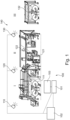
- Fig. 1 shows a control system 100 for a functional section I, II, III of a paper processing device 140.
- the control system 100 has at least one security camera 110, 120, 130, which is arranged in the functional section I, II, III, such that a functional area of the functional section I, II, III can be recorded using the security camera 110, 120, 130.
- An operating unit 101 of the system 100 is configured to operate the functional section I, II, III.
- the image data of the at least one security camera 110, 120, 130 can be selected using the operating unit 101.
- a display unit 103 is configured to display the selected image data so that a user can permit or block operation of the functional section I, II, III based on the displayed image data.
- a security device 102 can be provided, which is coupled to the security camera 110, 120, 130 and the operating unit 101, wherein the security device 102 receives image data from the security camera 110, 120, 130.
- the security device 102 is configured such that the Safety device 102, depending on the received image data of the safety camera 110, 120, 130, allows operation of the functional section I, II, III by means of the operating unit 101 or blocks operation of the functional section I, II, III by means of the operating unit 101.
- the paper processing device 140 is designed to process paper, in particular cardboard layers or cardboard boxes. During the processing process of the paper processing device 140, for example, cardboard boxes can be produced in multiple layers, cut to size, and/or printed.
- the paper processing device 140 has, in particular, a plurality of functional sections I, II, III, wherein each functional section I, II, III defines a processing step in a functional area.
- a functional section I, II, III comprises, for example, a stacking device (for stacking flat cardboard elements or for picking up individual cardboard elements from a stack), a laminating device (for gluing multiple layers of paper or cardboard layers), a paper feed device, and/or a drying device.
- the operating device 101 is designed to operate and control the functional sections I, II, III and, accordingly, the paper processing device 140.
- the operating device 101 is installed spatially remote from the functional sections I, II, III and, for example, the paper processing device 140.
- the operating device 101 can, for example, transmit control data to the paper processing device 140 via a wired or wireless connection in order to send control commands or receive status data or control data from the paper processing device 140.
- the operating unit 140 has an input element, such as a keyboard.
- the safety camera 110, 120, 130 or multiple safety cameras 110, 120, 130 of a group are assigned to a functional section I, II, III.
- the safety camera 110, 120, 130 records specific safety-relevant areas in the functional section I, II, III.
- the safety-relevant areas can represent maintenance areas, maintenance installations, or other movable machine elements in the functional section that are handled or moved by an operator during maintenance or repair. must be maintained.
- the safety cameras 110, 120, 130 monitor the safety-relevant areas of functional sections I, II, III and record image data (individual images or film sequences or live streams) and send the image data to the control unit 101 and/or the safety device 102.
- the user analyzes and evaluates the recorded image data. Furthermore, the safety device 102 can analyze and evaluate the recorded image data. Based on the recorded image data, the safety device 102 can lock or unlock the control unit 101. Additionally, the user can use the control unit 101 to lock the operation of functional sections I, II, and III.
- the safety device 102 If the safety device 102 detects, for example, a person in functional section I, II, III based on the image data, the safety device 102 locks the operating unit 101. This means that, for example, activation of the processing in functional section I, II, III from the operating unit 101 is not possible. If the operating unit 101 is located away from functional section I, II, III, remote control of functional section I, II, III is prevented. Alternatively, the safety device 102 can use the image data to detect whether the safety cameras 110, 120, 130 are functioning correctly. If the safety device 102 determines that the safety cameras 110, 120, 130 are not functioning correctly, the safety device 102 also locks the operating unit 101 to prevent a hasty and unnecessary termination of the process in functional section I, II, III.
- the control system has at least one process camera 112, 122, 132, which is arranged in the functional section I, II, III, such that a work process 111, 121, 131 in the functional section I, II, III can be recorded by the process camera 112, 122, 132.
- the process camera 112, 122, 132 is coupled to the display unit 103 or the operating unit 101 such that the user can terminate the work process 111, 121, 131 using the operating unit 101 based on the recorded work process.
- the process camera 112, 122, 132 can be coupled to the safety device 102 such that the safety device 102 can terminate the work process 111, 121, 131 based on the recorded work process.
- the process camera 112, 122, 132 captures, in particular, process-relevant images of the work process 111, 121, 131.
- the process camera 112, 122, 132 can record the position of a paper tape or the unwinding behavior of the paper tape from the roll. If the safety device 102 determines, based on the captured image data of the work process 111, 121, 131, that, for example, the track of a paper tape is incorrect, the safety device 102 can automatically terminate the work process 111, 121, 131.
- process camera 112, 122, 132 captures images of a work process 111, 121, 131, the safety camera 110, 120, 130, in comparison, captures the workspace in the functional area that can be entered by a person. It is certainly possible for a process camera 112, 122, 132 to function as a safety camera 110, 120, 130, and vice versa.
- the operating unit 101 can be used to select the image data of at least one security camera 110, 120, 130, with a display unit 103 configured to display the selected image data.
- the display unit 103 and the operating unit 101 are integrally formed, for example, as a touchscreen.
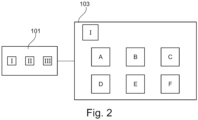
- Fig. 2 shows an exemplary representation of the operating unit 101 and the display unit 103.
- a desired functional section I is selected by means of the operating unit 101.
- the display unit 103 displays the functional section I of the paper processing device 140.
- the operating unit 101 is configured, based on the selected functional section I, to display the functional area of the functional section I recorded by the security camera 110 on the display unit 103 using camera recordings A to F from the security cameras 110 from the functional section I.
- the paper processing device 140 and its corresponding functional sections I, II, III can be displayed on the display unit 103 (e.g. a touch screen).
- a user can select this by pressing the operating unit 101 with a finger (e.g. a display area of a corresponding functional section I on the touch screen).
- images A to F of the security cameras 110 and/or the process camera 112 are displayed on the display unit 103. Furthermore, the The operating state of the work process 111, 121, 131 from functional section I can be displayed on the display unit 103. In addition, the user can be shown whether the safety camera 110 is providing image data that allows operation of the control unit 101 or not.
Landscapes
- Engineering & Computer Science (AREA)
- Physics & Mathematics (AREA)
- General Physics & Mathematics (AREA)
- Automation & Control Theory (AREA)
- General Engineering & Computer Science (AREA)
- Mechanical Engineering (AREA)
- Human Computer Interaction (AREA)
- Manufacturing & Machinery (AREA)
- Alarm Systems (AREA)
- Testing And Monitoring For Control Systems (AREA)
- Controlling Sheets Or Webs (AREA)
Applications Claiming Priority (2)
| Application Number | Priority Date | Filing Date | Title |
|---|---|---|---|
| DE102016109128 | 2016-05-18 | ||
| PCT/EP2017/025113 WO2017198342A1 (de) | 2016-05-18 | 2017-05-09 | Kontrollsystem für einen funktionsabschnitt einer papierverarbeitungsvorrichtung |
Publications (2)
| Publication Number | Publication Date |
|---|---|
| EP3458917A1 EP3458917A1 (de) | 2019-03-27 |
| EP3458917B1 true EP3458917B1 (de) | 2025-04-23 |
Family
ID=58707472
Family Applications (1)
| Application Number | Title | Priority Date | Filing Date |
|---|---|---|---|
| EP17723264.2A Active EP3458917B1 (de) | 2016-05-18 | 2017-05-09 | Kontrollsystem für einen funktionsabschnitt einer papierverarbeitungsvorrichtung |
Country Status (7)
| Country | Link |
|---|---|
| US (1) | US10865522B2 (pl) |
| EP (1) | EP3458917B1 (pl) |
| CN (1) | CN109154797B (pl) |
| ES (1) | ES3030500T3 (pl) |
| MX (1) | MX389306B (pl) |
| PL (1) | PL3458917T3 (pl) |
| WO (1) | WO2017198342A1 (pl) |
Families Citing this family (3)
| Publication number | Priority date | Publication date | Assignee | Title |
|---|---|---|---|---|
| US11726018B2 (en) * | 2018-11-30 | 2023-08-15 | Illinois Tool Works Inc. | Safety system interfaces and material testing systems including safety system interfaces |
| US11879871B2 (en) * | 2018-11-30 | 2024-01-23 | Illinois Tool Works Inc. | Safety systems requiring intentional function activation and material testing systems including safety systems requiring intentional function activation |
| CA3095666A1 (en) * | 2019-10-15 | 2021-04-15 | Ibs Of America | A system, control system, an inspection system, and a method of controlling and cleaning a steam box |
Citations (8)
| Publication number | Priority date | Publication date | Assignee | Title |
|---|---|---|---|---|
| DE19527832A1 (de) * | 1995-07-29 | 1997-02-06 | Werner & Pfleiderer Lebensmitt | Vorrichtung zum Beschicken und Entleeren von Industriebacköfen und Verfahren zum Betrieb einer derartigen Vorrichtung |
| US20030050735A1 (en) * | 2001-09-12 | 2003-03-13 | Michael Griffis | Safety circuit with automatic recovery |
| EP1479964A2 (de) * | 2003-05-22 | 2004-11-24 | Safecom Engineering Ag | Sicherheits-Fernsteuerung |
| DE102006048166A1 (de) * | 2006-08-02 | 2008-02-07 | Daimler Ag | Verfahren zur Beobachtung einer Person in einem industriellen Umfeld |
| WO2008028738A1 (de) * | 2006-09-08 | 2008-03-13 | Koenig & Bauer Aktiengesellschaft | Druckmaschine mit mindestens einem von einer mobilen bedieneinheit betätigten aggregat |
| US20140266678A1 (en) * | 2013-03-15 | 2014-09-18 | Adt Us Holdings, Inc. | Security system health monitoring |
| EP2858939A1 (en) * | 2012-06-07 | 2015-04-15 | Jaguar Land Rover Limited | Crane and related method of operation |
| DE102015003655A1 (de) * | 2014-03-28 | 2015-10-01 | Fanuc Corporation | Robotersystem zur Bestimmung eines Bedieners durch biometrische Authentifizierung |
Family Cites Families (13)
| Publication number | Priority date | Publication date | Assignee | Title |
|---|---|---|---|---|
| ATE122610T1 (de) * | 1990-02-28 | 1995-06-15 | Komori Printing Mach | Sicherheitsvorrichtung für eine druckmaschine. |
| US5717456A (en) * | 1995-03-06 | 1998-02-10 | Champion International Corporation | System for monitoring a continuous manufacturing process |
| CA2218563A1 (en) | 1996-10-18 | 1998-04-18 | Consolidated Papers, Inc. | Method of and system for video surveillance of a fast moving web |
| JP3670535B2 (ja) * | 1999-01-28 | 2005-07-13 | シャープ株式会社 | 画像情報伝送装置 |
| FI110343B (fi) * | 1999-02-25 | 2002-12-31 | Honeywell Oy | Paperikoneen ratakatkojen monitorointijärjestelmä |
| JP2001322238A (ja) * | 2000-05-17 | 2001-11-20 | Komori Corp | 印刷機 |
| DE10207871A1 (de) * | 2001-03-29 | 2002-10-10 | Heidelberger Druckmasch Ag | Sicherheitseinrichtung zur Überwachung eines nicht einsehbaren Gefahrenbereichs an einer Druckmaschine |
| DE10338973B4 (de) * | 2002-09-30 | 2013-01-31 | Goss International Montataire S.A. | Verfahren und Vorrichtung zur Störungserfassung beim Transport einer Materialbahn |
| DE102004055229A1 (de) * | 2004-11-17 | 2006-05-18 | Heidelberger Druckmaschinen Ag | Zustandsabhängige Absicherung von Maschinen |
| JP4199790B2 (ja) * | 2006-09-01 | 2008-12-17 | シャープ株式会社 | 画像処理装置 |
| JP4890393B2 (ja) * | 2007-08-28 | 2012-03-07 | 株式会社リコー | 用紙処理装置及び画像形成装置 |
| DE102009018477B4 (de) * | 2008-05-15 | 2025-06-12 | Heidelberger Druckmaschinen Ag | Videoüberwachte Druckmaschine |
| DE102009001026A1 (de) | 2009-02-20 | 2010-08-26 | Voith Patent Gmbh | Verfahren und Messvorrichtung zur optischen Erfassung und Auswertung einer Fasern beinhaltenden Bahn |
-
2017
- 2017-05-09 EP EP17723264.2A patent/EP3458917B1/de active Active
- 2017-05-09 ES ES17723264T patent/ES3030500T3/es active Active
- 2017-05-09 PL PL17723264.2T patent/PL3458917T3/pl unknown
- 2017-05-09 CN CN201780030078.XA patent/CN109154797B/zh active Active
- 2017-05-09 WO PCT/EP2017/025113 patent/WO2017198342A1/de not_active Ceased
- 2017-05-09 US US16/301,771 patent/US10865522B2/en active Active
- 2017-05-09 MX MX2018014125A patent/MX389306B/es unknown
Patent Citations (8)
| Publication number | Priority date | Publication date | Assignee | Title |
|---|---|---|---|---|
| DE19527832A1 (de) * | 1995-07-29 | 1997-02-06 | Werner & Pfleiderer Lebensmitt | Vorrichtung zum Beschicken und Entleeren von Industriebacköfen und Verfahren zum Betrieb einer derartigen Vorrichtung |
| US20030050735A1 (en) * | 2001-09-12 | 2003-03-13 | Michael Griffis | Safety circuit with automatic recovery |
| EP1479964A2 (de) * | 2003-05-22 | 2004-11-24 | Safecom Engineering Ag | Sicherheits-Fernsteuerung |
| DE102006048166A1 (de) * | 2006-08-02 | 2008-02-07 | Daimler Ag | Verfahren zur Beobachtung einer Person in einem industriellen Umfeld |
| WO2008028738A1 (de) * | 2006-09-08 | 2008-03-13 | Koenig & Bauer Aktiengesellschaft | Druckmaschine mit mindestens einem von einer mobilen bedieneinheit betätigten aggregat |
| EP2858939A1 (en) * | 2012-06-07 | 2015-04-15 | Jaguar Land Rover Limited | Crane and related method of operation |
| US20140266678A1 (en) * | 2013-03-15 | 2014-09-18 | Adt Us Holdings, Inc. | Security system health monitoring |
| DE102015003655A1 (de) * | 2014-03-28 | 2015-10-01 | Fanuc Corporation | Robotersystem zur Bestimmung eines Bedieners durch biometrische Authentifizierung |
Also Published As
| Publication number | Publication date |
|---|---|
| US20190211505A1 (en) | 2019-07-11 |
| ES3030500T3 (en) | 2025-06-30 |
| WO2017198342A1 (de) | 2017-11-23 |
| MX2018014125A (es) | 2019-04-29 |
| CN109154797B (zh) | 2021-11-23 |
| EP3458917A1 (de) | 2019-03-27 |
| PL3458917T3 (pl) | 2025-06-23 |
| US10865522B2 (en) | 2020-12-15 |
| CN109154797A (zh) | 2019-01-04 |
| MX389306B (es) | 2025-03-20 |
Similar Documents
| Publication | Publication Date | Title |
|---|---|---|
| EP3467601B1 (de) | Sicherheitssystem zur absicherung eines kooperativen betriebs von menschen, robotern und maschinen | |
| EP1367314B1 (de) | Vorrichtung zur Überwachung eines Erfassungsbereiches an einem Arbeitsmittel | |
| EP2637067B1 (de) | Sensoranordnung zum Detektieren eines sicheren Anlagenzustandes einer automatisiert betriebenen Anlage | |
| EP3152017B1 (de) | Verfahren zum betreiben einer plattenbearbeitungsanlage, sowie plattenbearbeitungsanlage | |
| EP2139803B1 (de) | Verfahren zum steuern einer lastbewegungsvorrichtung und steuerung einer lastbewegungsvorrichtung | |
| EP3458917B1 (de) | Kontrollsystem für einen funktionsabschnitt einer papierverarbeitungsvorrichtung | |
| DE10296623T5 (de) | Industrieller Roboter | |
| DE20321554U1 (de) | Objekterfassung und Lichtgitter | |
| EP2286393A1 (de) | Sicherheitsvorrichtung und verfahren zur überwachung eines überwachungsbereichs | |
| EP1662349B1 (de) | Absicherung von Maschinen in Abhängigkeit von deren Zustand | |
| DE19636703A1 (de) | Vorrichtung zur Steuerung eines automatischen Druckplattenwechsels | |
| EP2525268B1 (de) | Schaltvorrichtung für eine Maschine, eine Anlage und/oder ein Transportsystem | |
| AT521872A1 (de) | Verfahren zum Betreiben eines Maschinensteuerungssystems sowie entsprechendes Maschinensteuerungssystem | |
| DE102005050824A1 (de) | Verfahren zur ortsabhängigen Absicherung von gefährlichen Bereichen | |
| DE102018210625A1 (de) | Werkzeugmaschine mit Steuervorrichtung | |
| EP3371663B1 (de) | Steuerungssystem für elektrisch gesteuerte anlagen | |
| EP3447540B1 (de) | Lichtvorhang | |
| DE10207871A1 (de) | Sicherheitseinrichtung zur Überwachung eines nicht einsehbaren Gefahrenbereichs an einer Druckmaschine | |
| DE102005003254A1 (de) | Optoelektronischer Sensor und Konfigurationsverfahren | |
| DE60102177T2 (de) | Sicherheitseinrichtung für eine Rollenrotationsmaschine | |
| WO2017072246A1 (de) | Steuerungssystem für die sichere steuerung von maschinen | |
| DE102018106529A1 (de) | Druckmaschine und Verfahren zum Überwachen einer Druckmaschine | |
| EP4547575B1 (de) | Verbesserte umschaltung von einem energiesparmodus in einen normalbetriebsmodus in einem kommissioniersystem | |
| EP3058428A1 (de) | Mobile anlagensteuerung | |
| DE102006006133A1 (de) | Lichtschranke mit separaten Ausgangssignalen |
Legal Events
| Date | Code | Title | Description |
|---|---|---|---|
| STAA | Information on the status of an ep patent application or granted ep patent |
Free format text: STATUS: UNKNOWN |
|
| STAA | Information on the status of an ep patent application or granted ep patent |
Free format text: STATUS: THE INTERNATIONAL PUBLICATION HAS BEEN MADE |
|
| PUAI | Public reference made under article 153(3) epc to a published international application that has entered the european phase |
Free format text: ORIGINAL CODE: 0009012 |
|
| STAA | Information on the status of an ep patent application or granted ep patent |
Free format text: STATUS: REQUEST FOR EXAMINATION WAS MADE |
|
| 17P | Request for examination filed |
Effective date: 20181121 |
|
| AK | Designated contracting states |
Kind code of ref document: A1 Designated state(s): AL AT BE BG CH CY CZ DE DK EE ES FI FR GB GR HR HU IE IS IT LI LT LU LV MC MK MT NL NO PL PT RO RS SE SI SK SM TR |
|
| AX | Request for extension of the european patent |
Extension state: BA ME |
|
| DAV | Request for validation of the european patent (deleted) | ||
| DAX | Request for extension of the european patent (deleted) | ||
| STAA | Information on the status of an ep patent application or granted ep patent |
Free format text: STATUS: EXAMINATION IS IN PROGRESS |
|
| 17Q | First examination report despatched |
Effective date: 20210122 |
|
| RAP1 | Party data changed (applicant data changed or rights of an application transferred) |
Owner name: BOBST MEX SA |
|
| REG | Reference to a national code |
Ref country code: DE Free format text: PREVIOUS MAIN CLASS: G05B0009020000 Ipc: G05B0019406100 Ref country code: DE Ref legal event code: R079 Ref document number: 502017016810 Country of ref document: DE Free format text: PREVIOUS MAIN CLASS: G05B0009020000 Ipc: G05B0019406100 |
|
| GRAP | Despatch of communication of intention to grant a patent |
Free format text: ORIGINAL CODE: EPIDOSNIGR1 |
|
| STAA | Information on the status of an ep patent application or granted ep patent |
Free format text: STATUS: GRANT OF PATENT IS INTENDED |
|
| RIC1 | Information provided on ipc code assigned before grant |
Ipc: G05B 19/4061 20060101AFI20241119BHEP |
|
| INTG | Intention to grant announced |
Effective date: 20241206 |
|
| GRAS | Grant fee paid |
Free format text: ORIGINAL CODE: EPIDOSNIGR3 |
|
| GRAA | (expected) grant |
Free format text: ORIGINAL CODE: 0009210 |
|
| STAA | Information on the status of an ep patent application or granted ep patent |
Free format text: STATUS: THE PATENT HAS BEEN GRANTED |
|
| AK | Designated contracting states |
Kind code of ref document: B1 Designated state(s): AL AT BE BG CH CY CZ DE DK EE ES FI FR GB GR HR HU IE IS IT LI LT LU LV MC MK MT NL NO PL PT RO RS SE SI SK SM TR |
|
| REG | Reference to a national code |
Ref country code: GB Ref legal event code: FG4D Free format text: NOT ENGLISH |
|
| REG | Reference to a national code |
Ref country code: CH Ref legal event code: EP |
|
| REG | Reference to a national code |
Ref country code: DE Ref legal event code: R096 Ref document number: 502017016810 Country of ref document: DE |
|
| REG | Reference to a national code |
Ref country code: IE Ref legal event code: FG4D Free format text: LANGUAGE OF EP DOCUMENT: GERMAN |
|
| REG | Reference to a national code |
Ref country code: ES Ref legal event code: FG2A Ref document number: 3030500 Country of ref document: ES Kind code of ref document: T3 Effective date: 20250630 |
|
| PGFP | Annual fee paid to national office [announced via postgrant information from national office to epo] |
Ref country code: PL Payment date: 20250514 Year of fee payment: 9 Ref country code: DE Payment date: 20250514 Year of fee payment: 9 |
|
| PGFP | Annual fee paid to national office [announced via postgrant information from national office to epo] |
Ref country code: GB Payment date: 20250508 Year of fee payment: 9 Ref country code: ES Payment date: 20250606 Year of fee payment: 9 |
|
| PGFP | Annual fee paid to national office [announced via postgrant information from national office to epo] |
Ref country code: FR Payment date: 20250505 Year of fee payment: 9 |
|
| REG | Reference to a national code |
Ref country code: NL Ref legal event code: MP Effective date: 20250423 |
|
| PG25 | Lapsed in a contracting state [announced via postgrant information from national office to epo] |
Ref country code: NL Free format text: LAPSE BECAUSE OF FAILURE TO SUBMIT A TRANSLATION OF THE DESCRIPTION OR TO PAY THE FEE WITHIN THE PRESCRIBED TIME-LIMIT Effective date: 20250423 |
|
| PG25 | Lapsed in a contracting state [announced via postgrant information from national office to epo] |
Ref country code: FI Free format text: LAPSE BECAUSE OF FAILURE TO SUBMIT A TRANSLATION OF THE DESCRIPTION OR TO PAY THE FEE WITHIN THE PRESCRIBED TIME-LIMIT Effective date: 20250423 Ref country code: PT Free format text: LAPSE BECAUSE OF FAILURE TO SUBMIT A TRANSLATION OF THE DESCRIPTION OR TO PAY THE FEE WITHIN THE PRESCRIBED TIME-LIMIT Effective date: 20250825 |
|
| REG | Reference to a national code |
Ref country code: LT Ref legal event code: MG9D |
|
| PG25 | Lapsed in a contracting state [announced via postgrant information from national office to epo] |
Ref country code: NO Free format text: LAPSE BECAUSE OF FAILURE TO SUBMIT A TRANSLATION OF THE DESCRIPTION OR TO PAY THE FEE WITHIN THE PRESCRIBED TIME-LIMIT Effective date: 20250723 Ref country code: GR Free format text: LAPSE BECAUSE OF FAILURE TO SUBMIT A TRANSLATION OF THE DESCRIPTION OR TO PAY THE FEE WITHIN THE PRESCRIBED TIME-LIMIT Effective date: 20250724 |
|
| PGFP | Annual fee paid to national office [announced via postgrant information from national office to epo] |
Ref country code: IT Payment date: 20250611 Year of fee payment: 9 |
|
| PG25 | Lapsed in a contracting state [announced via postgrant information from national office to epo] |
Ref country code: BG Free format text: LAPSE BECAUSE OF FAILURE TO SUBMIT A TRANSLATION OF THE DESCRIPTION OR TO PAY THE FEE WITHIN THE PRESCRIBED TIME-LIMIT Effective date: 20250423 |
|
| PG25 | Lapsed in a contracting state [announced via postgrant information from national office to epo] |
Ref country code: HR Free format text: LAPSE BECAUSE OF FAILURE TO SUBMIT A TRANSLATION OF THE DESCRIPTION OR TO PAY THE FEE WITHIN THE PRESCRIBED TIME-LIMIT Effective date: 20250423 |
|
| PG25 | Lapsed in a contracting state [announced via postgrant information from national office to epo] |
Ref country code: RS Free format text: LAPSE BECAUSE OF FAILURE TO SUBMIT A TRANSLATION OF THE DESCRIPTION OR TO PAY THE FEE WITHIN THE PRESCRIBED TIME-LIMIT Effective date: 20250723 |
|
| PG25 | Lapsed in a contracting state [announced via postgrant information from national office to epo] |
Ref country code: IS Free format text: LAPSE BECAUSE OF FAILURE TO SUBMIT A TRANSLATION OF THE DESCRIPTION OR TO PAY THE FEE WITHIN THE PRESCRIBED TIME-LIMIT Effective date: 20250823 |
|
| PG25 | Lapsed in a contracting state [announced via postgrant information from national office to epo] |
Ref country code: LV Free format text: LAPSE BECAUSE OF FAILURE TO SUBMIT A TRANSLATION OF THE DESCRIPTION OR TO PAY THE FEE WITHIN THE PRESCRIBED TIME-LIMIT Effective date: 20250423 |
|
| REG | Reference to a national code |
Ref country code: CH Ref legal event code: H13 Free format text: ST27 STATUS EVENT CODE: U-0-0-H10-H13 (AS PROVIDED BY THE NATIONAL OFFICE) Effective date: 20251223 |
|
| PG25 | Lapsed in a contracting state [announced via postgrant information from national office to epo] |
Ref country code: SM Free format text: LAPSE BECAUSE OF FAILURE TO SUBMIT A TRANSLATION OF THE DESCRIPTION OR TO PAY THE FEE WITHIN THE PRESCRIBED TIME-LIMIT Effective date: 20250423 Ref country code: DK Free format text: LAPSE BECAUSE OF FAILURE TO SUBMIT A TRANSLATION OF THE DESCRIPTION OR TO PAY THE FEE WITHIN THE PRESCRIBED TIME-LIMIT Effective date: 20250423 |
|
| PG25 | Lapsed in a contracting state [announced via postgrant information from national office to epo] |
Ref country code: LU Free format text: LAPSE BECAUSE OF NON-PAYMENT OF DUE FEES Effective date: 20250509 |
|
| PG25 | Lapsed in a contracting state [announced via postgrant information from national office to epo] |
Ref country code: CH Free format text: LAPSE BECAUSE OF NON-PAYMENT OF DUE FEES Effective date: 20250531 |
|
| PG25 | Lapsed in a contracting state [announced via postgrant information from national office to epo] |
Ref country code: CZ Free format text: LAPSE BECAUSE OF FAILURE TO SUBMIT A TRANSLATION OF THE DESCRIPTION OR TO PAY THE FEE WITHIN THE PRESCRIBED TIME-LIMIT Effective date: 20250423 |
|
| PG25 | Lapsed in a contracting state [announced via postgrant information from national office to epo] |
Ref country code: EE Free format text: LAPSE BECAUSE OF FAILURE TO SUBMIT A TRANSLATION OF THE DESCRIPTION OR TO PAY THE FEE WITHIN THE PRESCRIBED TIME-LIMIT Effective date: 20250423 |
|
| REG | Reference to a national code |
Ref country code: DE Ref legal event code: R097 Ref document number: 502017016810 Country of ref document: DE |
|
| PG25 | Lapsed in a contracting state [announced via postgrant information from national office to epo] |
Ref country code: SK Free format text: LAPSE BECAUSE OF FAILURE TO SUBMIT A TRANSLATION OF THE DESCRIPTION OR TO PAY THE FEE WITHIN THE PRESCRIBED TIME-LIMIT Effective date: 20250423 Ref country code: RO Free format text: LAPSE BECAUSE OF FAILURE TO SUBMIT A TRANSLATION OF THE DESCRIPTION OR TO PAY THE FEE WITHIN THE PRESCRIBED TIME-LIMIT Effective date: 20250423 |
|
| REG | Reference to a national code |
Ref country code: BE Ref legal event code: MM Effective date: 20250531 |
|
| PG25 | Lapsed in a contracting state [announced via postgrant information from national office to epo] |
Ref country code: MC Free format text: LAPSE BECAUSE OF FAILURE TO SUBMIT A TRANSLATION OF THE DESCRIPTION OR TO PAY THE FEE WITHIN THE PRESCRIBED TIME-LIMIT Effective date: 20250423 |
|
| PLBE | No opposition filed within time limit |
Free format text: ORIGINAL CODE: 0009261 |
|
| STAA | Information on the status of an ep patent application or granted ep patent |
Free format text: STATUS: NO OPPOSITION FILED WITHIN TIME LIMIT |
|
| REG | Reference to a national code |
Ref country code: CH Ref legal event code: L10 Free format text: ST27 STATUS EVENT CODE: U-0-0-L10-L00 (AS PROVIDED BY THE NATIONAL OFFICE) Effective date: 20260304 |
|
| 26N | No opposition filed |
Effective date: 20260126 |
|
| PG25 | Lapsed in a contracting state [announced via postgrant information from national office to epo] |
Ref country code: IE Free format text: LAPSE BECAUSE OF NON-PAYMENT OF DUE FEES Effective date: 20250509 |
|
| PG25 | Lapsed in a contracting state [announced via postgrant information from national office to epo] |
Ref country code: BE Free format text: LAPSE BECAUSE OF NON-PAYMENT OF DUE FEES Effective date: 20250531 |