EP3459480A1 - Appareil permettant de localiser un champ électrique - Google Patents
Appareil permettant de localiser un champ électrique Download PDFInfo
- Publication number
- EP3459480A1 EP3459480A1 EP17192463.2A EP17192463A EP3459480A1 EP 3459480 A1 EP3459480 A1 EP 3459480A1 EP 17192463 A EP17192463 A EP 17192463A EP 3459480 A1 EP3459480 A1 EP 3459480A1
- Authority
- EP
- European Patent Office
- Prior art keywords
- electrodes
- electroporation
- catheter
- catheter tip
- electrode
- Prior art date
- Legal status (The legal status is an assumption and is not a legal conclusion. Google has not performed a legal analysis and makes no representation as to the accuracy of the status listed.)
- Withdrawn
Links
- 230000005684 electric field Effects 0.000 title claims abstract description 55
- 238000004520 electroporation Methods 0.000 claims abstract description 100
- 230000000694 effects Effects 0.000 claims abstract description 10
- 238000000034 method Methods 0.000 claims description 39
- 230000007831 electrophysiology Effects 0.000 claims description 21
- 238000002001 electrophysiology Methods 0.000 claims description 21
- 206010003658 Atrial Fibrillation Diseases 0.000 claims description 17
- 210000000709 aorta Anatomy 0.000 claims description 16
- 210000002216 heart Anatomy 0.000 claims description 16
- 210000002620 vena cava superior Anatomy 0.000 claims description 15
- 210000004351 coronary vessel Anatomy 0.000 claims description 12
- 239000012530 fluid Substances 0.000 claims description 12
- 210000001147 pulmonary artery Anatomy 0.000 claims description 11
- 238000011282 treatment Methods 0.000 claims description 10
- FAPWRFPIFSIZLT-UHFFFAOYSA-M Sodium chloride Chemical compound [Na+].[Cl-] FAPWRFPIFSIZLT-UHFFFAOYSA-M 0.000 claims description 8
- 230000000712 assembly Effects 0.000 claims description 8
- 238000000429 assembly Methods 0.000 claims description 8
- 229910052751 metal Inorganic materials 0.000 claims description 8
- 239000002184 metal Substances 0.000 claims description 8
- 239000011780 sodium chloride Substances 0.000 claims description 8
- 230000008859 change Effects 0.000 claims description 5
- 230000008878 coupling Effects 0.000 claims description 4
- 238000010168 coupling process Methods 0.000 claims description 4
- 238000005859 coupling reaction Methods 0.000 claims description 4
- 229920000642 polymer Polymers 0.000 claims description 4
- 230000000903 blocking effect Effects 0.000 claims description 2
- 238000004891 communication Methods 0.000 claims description 2
- 238000013022 venting Methods 0.000 claims description 2
- 230000002401 inhibitory effect Effects 0.000 claims 1
- 210000001519 tissue Anatomy 0.000 description 56
- 210000000577 adipose tissue Anatomy 0.000 description 18
- 210000004165 myocardium Anatomy 0.000 description 16
- 238000001816 cooling Methods 0.000 description 15
- 210000000609 ganglia Anatomy 0.000 description 15
- 238000002679 ablation Methods 0.000 description 14
- 238000010438 heat treatment Methods 0.000 description 10
- 230000006378 damage Effects 0.000 description 9
- 230000002262 irrigation Effects 0.000 description 7
- 238000003973 irrigation Methods 0.000 description 7
- 239000004020 conductor Substances 0.000 description 6
- 210000004027 cell Anatomy 0.000 description 5
- 238000013153 catheter ablation Methods 0.000 description 4
- 210000002569 neuron Anatomy 0.000 description 4
- 230000002685 pulmonary effect Effects 0.000 description 4
- 230000033764 rhythmic process Effects 0.000 description 4
- 210000001782 transverse sinus Anatomy 0.000 description 4
- 230000002427 irreversible effect Effects 0.000 description 3
- 230000033001 locomotion Effects 0.000 description 3
- 238000005259 measurement Methods 0.000 description 3
- 230000037361 pathway Effects 0.000 description 3
- 210000003102 pulmonary valve Anatomy 0.000 description 3
- 210000003492 pulmonary vein Anatomy 0.000 description 3
- 210000005245 right atrium Anatomy 0.000 description 3
- 238000001356 surgical procedure Methods 0.000 description 3
- XKRFYHLGVUSROY-UHFFFAOYSA-N Argon Chemical compound [Ar] XKRFYHLGVUSROY-UHFFFAOYSA-N 0.000 description 2
- 238000011298 ablation treatment Methods 0.000 description 2
- 230000002159 abnormal effect Effects 0.000 description 2
- 230000005856 abnormality Effects 0.000 description 2
- 210000003484 anatomy Anatomy 0.000 description 2
- 230000003466 anti-cipated effect Effects 0.000 description 2
- 210000001765 aortic valve Anatomy 0.000 description 2
- 238000013459 approach Methods 0.000 description 2
- 206010003119 arrhythmia Diseases 0.000 description 2
- 230000001746 atrial effect Effects 0.000 description 2
- 210000003403 autonomic nervous system Anatomy 0.000 description 2
- 230000008901 benefit Effects 0.000 description 2
- 230000005540 biological transmission Effects 0.000 description 2
- 239000008280 blood Substances 0.000 description 2
- 210000004369 blood Anatomy 0.000 description 2
- 210000004413 cardiac myocyte Anatomy 0.000 description 2
- 210000003191 femoral vein Anatomy 0.000 description 2
- 210000005003 heart tissue Anatomy 0.000 description 2
- 239000012212 insulator Substances 0.000 description 2
- 230000003902 lesion Effects 0.000 description 2
- 230000000670 limiting effect Effects 0.000 description 2
- 230000002107 myocardial effect Effects 0.000 description 2
- 229910001000 nickel titanium Inorganic materials 0.000 description 2
- 210000000056 organ Anatomy 0.000 description 2
- 230000036279 refractory period Effects 0.000 description 2
- 238000011160 research Methods 0.000 description 2
- 230000002441 reversible effect Effects 0.000 description 2
- 210000005241 right ventricle Anatomy 0.000 description 2
- 210000000591 tricuspid valve Anatomy 0.000 description 2
- 210000001631 vena cava inferior Anatomy 0.000 description 2
- 230000002861 ventricular Effects 0.000 description 2
- PDWUPXJEEYOOTR-UHFFFAOYSA-N 2-[(3-iodophenyl)methyl]guanidine Chemical compound NC(=N)NCC1=CC=CC(I)=C1 PDWUPXJEEYOOTR-UHFFFAOYSA-N 0.000 description 1
- 206010002091 Anaesthesia Diseases 0.000 description 1
- 206010003662 Atrial flutter Diseases 0.000 description 1
- 208000024172 Cardiovascular disease Diseases 0.000 description 1
- RYGMFSIKBFXOCR-UHFFFAOYSA-N Copper Chemical compound [Cu] RYGMFSIKBFXOCR-UHFFFAOYSA-N 0.000 description 1
- 208000003098 Ganglion Cysts Diseases 0.000 description 1
- 206010019280 Heart failures Diseases 0.000 description 1
- 240000002834 Paulownia tomentosa Species 0.000 description 1
- 235000010678 Paulownia tomentosa Nutrition 0.000 description 1
- 208000005400 Synovial Cyst Diseases 0.000 description 1
- 208000007536 Thrombosis Diseases 0.000 description 1
- 229910045601 alloy Inorganic materials 0.000 description 1
- 239000000956 alloy Substances 0.000 description 1
- 238000001949 anaesthesia Methods 0.000 description 1
- 230000037005 anaesthesia Effects 0.000 description 1
- 210000002376 aorta thoracic Anatomy 0.000 description 1
- 229910052786 argon Inorganic materials 0.000 description 1
- 230000006793 arrhythmia Effects 0.000 description 1
- 210000001367 artery Anatomy 0.000 description 1
- 206010003668 atrial tachycardia Diseases 0.000 description 1
- 210000002453 autonomic neuron Anatomy 0.000 description 1
- 210000000467 autonomic pathway Anatomy 0.000 description 1
- 210000003050 axon Anatomy 0.000 description 1
- 230000015572 biosynthetic process Effects 0.000 description 1
- 210000004204 blood vessel Anatomy 0.000 description 1
- 230000000747 cardiac effect Effects 0.000 description 1
- 230000002612 cardiopulmonary effect Effects 0.000 description 1
- 230000005800 cardiovascular problem Effects 0.000 description 1
- 210000005056 cell body Anatomy 0.000 description 1
- 230000030833 cell death Effects 0.000 description 1
- 230000001413 cellular effect Effects 0.000 description 1
- 229910052802 copper Inorganic materials 0.000 description 1
- 239000010949 copper Substances 0.000 description 1
- 230000003247 decreasing effect Effects 0.000 description 1
- 230000001419 dependent effect Effects 0.000 description 1
- 238000006073 displacement reaction Methods 0.000 description 1
- 229940079593 drug Drugs 0.000 description 1
- 239000003814 drug Substances 0.000 description 1
- 230000002526 effect on cardiovascular system Effects 0.000 description 1
- 238000010292 electrical insulation Methods 0.000 description 1
- 238000011156 evaluation Methods 0.000 description 1
- 210000001105 femoral artery Anatomy 0.000 description 1
- 239000000835 fiber Substances 0.000 description 1
- 238000010304 firing Methods 0.000 description 1
- 210000002837 heart atrium Anatomy 0.000 description 1
- 239000001307 helium Substances 0.000 description 1
- 229910052734 helium Inorganic materials 0.000 description 1
- SWQJXJOGLNCZEY-UHFFFAOYSA-N helium atom Chemical compound [He] SWQJXJOGLNCZEY-UHFFFAOYSA-N 0.000 description 1
- 230000023597 hemostasis Effects 0.000 description 1
- 210000003090 iliac artery Anatomy 0.000 description 1
- 210000003111 iliac vein Anatomy 0.000 description 1
- 238000003384 imaging method Methods 0.000 description 1
- 230000000977 initiatory effect Effects 0.000 description 1
- 230000030214 innervation Effects 0.000 description 1
- 230000001788 irregular Effects 0.000 description 1
- 210000004731 jugular vein Anatomy 0.000 description 1
- 210000005240 left ventricle Anatomy 0.000 description 1
- 230000007246 mechanism Effects 0.000 description 1
- 238000012986 modification Methods 0.000 description 1
- 230000004048 modification Effects 0.000 description 1
- 210000005036 nerve Anatomy 0.000 description 1
- HLXZNVUGXRDIFK-UHFFFAOYSA-N nickel titanium Chemical compound [Ti].[Ti].[Ti].[Ti].[Ti].[Ti].[Ti].[Ti].[Ti].[Ti].[Ti].[Ni].[Ni].[Ni].[Ni].[Ni].[Ni].[Ni].[Ni].[Ni].[Ni].[Ni].[Ni].[Ni].[Ni] HLXZNVUGXRDIFK-UHFFFAOYSA-N 0.000 description 1
- 230000001314 paroxysmal effect Effects 0.000 description 1
- 210000003516 pericardium Anatomy 0.000 description 1
- 230000008569 process Effects 0.000 description 1
- 230000000750 progressive effect Effects 0.000 description 1
- 230000002829 reductive effect Effects 0.000 description 1
- 208000037803 restenosis Diseases 0.000 description 1
- 239000010935 stainless steel Substances 0.000 description 1
- 229910001220 stainless steel Inorganic materials 0.000 description 1
- 210000001321 subclavian vein Anatomy 0.000 description 1
- 230000002459 sustained effect Effects 0.000 description 1
- 230000008685 targeting Effects 0.000 description 1
- 230000003685 thermal hair damage Effects 0.000 description 1
- 230000000451 tissue damage Effects 0.000 description 1
- 231100000827 tissue damage Toxicity 0.000 description 1
- 238000002604 ultrasonography Methods 0.000 description 1
- 230000002792 vascular Effects 0.000 description 1
- 210000003462 vein Anatomy 0.000 description 1
- 230000003313 weakening effect Effects 0.000 description 1
Images




Classifications
-
- A—HUMAN NECESSITIES
- A61—MEDICAL OR VETERINARY SCIENCE; HYGIENE
- A61B—DIAGNOSIS; SURGERY; IDENTIFICATION
- A61B18/00—Surgical instruments, devices or methods for transferring non-mechanical forms of energy to or from the body
- A61B18/04—Surgical instruments, devices or methods for transferring non-mechanical forms of energy to or from the body by heating
- A61B18/12—Surgical instruments, devices or methods for transferring non-mechanical forms of energy to or from the body by heating by passing a current through the tissue to be heated, e.g. high-frequency current
- A61B18/14—Probes or electrodes therefor
- A61B18/1492—Probes or electrodes therefor having a flexible, catheter-like structure, e.g. for heart ablation
-
- A—HUMAN NECESSITIES
- A61—MEDICAL OR VETERINARY SCIENCE; HYGIENE
- A61B—DIAGNOSIS; SURGERY; IDENTIFICATION
- A61B18/00—Surgical instruments, devices or methods for transferring non-mechanical forms of energy to or from the body
- A61B2018/00005—Cooling or heating of the probe or tissue immediately surrounding the probe
- A61B2018/00011—Cooling or heating of the probe or tissue immediately surrounding the probe with fluids
- A61B2018/00023—Cooling or heating of the probe or tissue immediately surrounding the probe with fluids closed, i.e. without wound contact by the fluid
-
- A—HUMAN NECESSITIES
- A61—MEDICAL OR VETERINARY SCIENCE; HYGIENE
- A61B—DIAGNOSIS; SURGERY; IDENTIFICATION
- A61B18/00—Surgical instruments, devices or methods for transferring non-mechanical forms of energy to or from the body
- A61B2018/00053—Mechanical features of the instrument of device
- A61B2018/00214—Expandable means emitting energy, e.g. by elements carried thereon
- A61B2018/0022—Balloons
-
- A—HUMAN NECESSITIES
- A61—MEDICAL OR VETERINARY SCIENCE; HYGIENE
- A61B—DIAGNOSIS; SURGERY; IDENTIFICATION
- A61B18/00—Surgical instruments, devices or methods for transferring non-mechanical forms of energy to or from the body
- A61B2018/00315—Surgical instruments, devices or methods for transferring non-mechanical forms of energy to or from the body for treatment of particular body parts
- A61B2018/00345—Vascular system
- A61B2018/00351—Heart
- A61B2018/00363—Epicardium
-
- A—HUMAN NECESSITIES
- A61—MEDICAL OR VETERINARY SCIENCE; HYGIENE
- A61B—DIAGNOSIS; SURGERY; IDENTIFICATION
- A61B18/00—Surgical instruments, devices or methods for transferring non-mechanical forms of energy to or from the body
- A61B2018/00315—Surgical instruments, devices or methods for transferring non-mechanical forms of energy to or from the body for treatment of particular body parts
- A61B2018/00434—Neural system
-
- A—HUMAN NECESSITIES
- A61—MEDICAL OR VETERINARY SCIENCE; HYGIENE
- A61B—DIAGNOSIS; SURGERY; IDENTIFICATION
- A61B18/00—Surgical instruments, devices or methods for transferring non-mechanical forms of energy to or from the body
- A61B2018/00571—Surgical instruments, devices or methods for transferring non-mechanical forms of energy to or from the body for achieving a particular surgical effect
- A61B2018/00613—Irreversible electroporation
-
- A—HUMAN NECESSITIES
- A61—MEDICAL OR VETERINARY SCIENCE; HYGIENE
- A61B—DIAGNOSIS; SURGERY; IDENTIFICATION
- A61B18/00—Surgical instruments, devices or methods for transferring non-mechanical forms of energy to or from the body
- A61B2018/00636—Sensing and controlling the application of energy
- A61B2018/00642—Sensing and controlling the application of energy with feedback, i.e. closed loop control
- A61B2018/00654—Sensing and controlling the application of energy with feedback, i.e. closed loop control with individual control of each of a plurality of energy emitting elements
-
- A—HUMAN NECESSITIES
- A61—MEDICAL OR VETERINARY SCIENCE; HYGIENE
- A61B—DIAGNOSIS; SURGERY; IDENTIFICATION
- A61B18/00—Surgical instruments, devices or methods for transferring non-mechanical forms of energy to or from the body
- A61B2018/00636—Sensing and controlling the application of energy
- A61B2018/0066—Sensing and controlling the application of energy without feedback, i.e. open loop control
-
- A—HUMAN NECESSITIES
- A61—MEDICAL OR VETERINARY SCIENCE; HYGIENE
- A61B—DIAGNOSIS; SURGERY; IDENTIFICATION
- A61B18/00—Surgical instruments, devices or methods for transferring non-mechanical forms of energy to or from the body
- A61B2018/00636—Sensing and controlling the application of energy
- A61B2018/00696—Controlled or regulated parameters
- A61B2018/00761—Duration
-
- A—HUMAN NECESSITIES
- A61—MEDICAL OR VETERINARY SCIENCE; HYGIENE
- A61B—DIAGNOSIS; SURGERY; IDENTIFICATION
- A61B18/00—Surgical instruments, devices or methods for transferring non-mechanical forms of energy to or from the body
- A61B2018/00636—Sensing and controlling the application of energy
- A61B2018/00696—Controlled or regulated parameters
- A61B2018/00767—Voltage
-
- A—HUMAN NECESSITIES
- A61—MEDICAL OR VETERINARY SCIENCE; HYGIENE
- A61B—DIAGNOSIS; SURGERY; IDENTIFICATION
- A61B18/00—Surgical instruments, devices or methods for transferring non-mechanical forms of energy to or from the body
- A61B18/04—Surgical instruments, devices or methods for transferring non-mechanical forms of energy to or from the body by heating
- A61B18/12—Surgical instruments, devices or methods for transferring non-mechanical forms of energy to or from the body by heating by passing a current through the tissue to be heated, e.g. high-frequency current
- A61B18/1206—Generators therefor
- A61B2018/1266—Generators therefor with DC current output
-
- A—HUMAN NECESSITIES
- A61—MEDICAL OR VETERINARY SCIENCE; HYGIENE
- A61B—DIAGNOSIS; SURGERY; IDENTIFICATION
- A61B18/00—Surgical instruments, devices or methods for transferring non-mechanical forms of energy to or from the body
- A61B18/04—Surgical instruments, devices or methods for transferring non-mechanical forms of energy to or from the body by heating
- A61B18/12—Surgical instruments, devices or methods for transferring non-mechanical forms of energy to or from the body by heating by passing a current through the tissue to be heated, e.g. high-frequency current
- A61B18/14—Probes or electrodes therefor
- A61B2018/1405—Electrodes having a specific shape
- A61B2018/1407—Loop
-
- A—HUMAN NECESSITIES
- A61—MEDICAL OR VETERINARY SCIENCE; HYGIENE
- A61B—DIAGNOSIS; SURGERY; IDENTIFICATION
- A61B18/00—Surgical instruments, devices or methods for transferring non-mechanical forms of energy to or from the body
- A61B18/04—Surgical instruments, devices or methods for transferring non-mechanical forms of energy to or from the body by heating
- A61B18/12—Surgical instruments, devices or methods for transferring non-mechanical forms of energy to or from the body by heating by passing a current through the tissue to be heated, e.g. high-frequency current
- A61B18/14—Probes or electrodes therefor
- A61B2018/1467—Probes or electrodes therefor using more than two electrodes on a single probe
Definitions
- This disclosure relates to apparatus useful in the medical field.
- the apparatus may be useful in the treatment of atrial fibrillation.
- Atrial fibrillation is one heart condition in which the heart beats in an irregular fashion, often much faster than is considered normal. Undiagnosed or untreated atrial fibrillation may lead to weakening of the heart and the potential for heart failure.
- Atrial fibrillation can be controlled in suitable subjects by medication or by electrical stimuli (controlled electric shock) to restore a normal rhythm, or by means of catheter ablation of abnormal heart tissue.
- electrical stimuli controlled electric shock
- a thin catheter bearing electrodes is introduced to the heart via a blood vessel, and an area of tissue abnormality can be identified according to evaluation of electrical activity of the heart tissue.
- the area of tissue abnormality can be ablated by introducing high radio frequency energy via the catheter to create localised heat to target the tissue to be ablated.
- a cryoablation technique can be used. Cryoablation may use argon or helium delivered under high pressure via a catheter to achieve temperatures of -55 to -90 °C at the catheter tip. Tissue adjacent the tip may be cooled for about 2 minutes leading to subsequent formation of very localised lesions with adjacent tissue being unaffected. Ablation of the abnormal tissue may allow the restoration of normal rhythm of the heart.
- Epicardial (external surface) sites may also contribute to initiation of atrial fibrillation.
- Sites where clusters of autonomic neurons interface with each other and with the heart itself are known as the ganglionated plexi sites, which are typically embedded within fat pads on the epicardial surface of the heart, but can be in direct contact with the myocardium.
- the ganglionated plexi can be ablated using radiofrequency or cryoablation during open surgery, thorascopic surgery, or from an endocardial position via the myocardium.
- ablation techniques are not well suited to ablation of the ganglionated plexi sites within the transverse sinus and aortocaval sinus (superior sinus) due to the risk of thermal or physical damage to collateral structures.
- aortocaval ganglionated plexi and the aortic root ganglionated plexi are evidently significant with regard to atrial fibrillation in comparison with other ganglionated plexi sites, they are difficult to access surgically, and their proximity to critical arterial structures that could be easily damaged is a relevant factor in devising a procedure. Surgical access to these sites at the top of the heart requires more extensive tissue cutting and displacement compared to other ganglionated plexi on the rear surfaces of the heart. This necessitates longer procedures with the associated risks of longer cardiopulmonary pump time.
- the current energy sources used for ablation present a hazard to the arteries and veins that are grouped tightly in this location, including the pulmonary artery, the aorta, the right and left coronary arteries and the superior vena cava. Damage due to RF or cryo energy can cause lesions leading to thrombus, restenosis, and occlusion as well as potentially causing perforation. Taking these challenging factors into consideration, the ganglionated plexi at these sites are not usually targeted which limits the ability to reduce atrial fibrillation through ablation of these autonomic nerve sites.
- EP 2 986 243 A1 discloses a method and a device for modulating the autonomic nervous system adjacent a pericardial space to treat cardiac arrhythmia.
- the device performs modulation or ablation of the autonomic nervous system at selected treatment areas within the pericardium.
- Electroporation may be considered as an alternative to ablation. This is an athermal process that involves application of high voltage direct current pulses for very short durations which avoids heat build-up, for example applying 1000 volts for 100 ⁇ s. However, the efficacy of electroporation is also temperature dependent, with the threshold for electroporation being decreased at elevated temperatures. Electroporation could selectively ablate neurons in a targeted manner without discernible collateral damage to surrounding structures such as myocardium and arterial or venous tissue.
- Electrophysiology apparatus disclosed herein comprises a high voltage pulsed DC supply, and at least one catheter configured for endocardial access, the catheter including a catheter tip and electrode assembly connectable with the high voltage pulsed DC supply.
- the electrophysiology apparatus may comprise a catheter assembly including more than one catheter including a catheter tip and electrode assembly so that the electrophysiology apparatus comprises at least two electroporation electrodes connectable with the high voltage pulsed DC supply such that the at least two electroporation electrodes are oppositely charged.
- a catheter assembly means a plurality of catheters capable of being introduced to target tissue, and arranged to be used together in an operational space including target tissue for the purposes of modifying the target tissue by electroporation.
- Each such catheter of the catheter assembly may have a proximal end adapted for a user control, for example to manipulate the catheter, and a distal end referred to herein as a catheter tip, which catheter tip is configured for introduction endocardially via a lumen of a natural vessel selected from any of the superior vena cava, the aorta, pulmonary arteries, coronary arteries.
- the catheter tip may have one of more selectively controllable electrodes located thereon.
- the catheter tip and electrode(s) together provide a catheter tip and electrode assembly.
- Each catheter tip and electrode assembly can be used as an electroporation electrode when connected to a high voltage pulsed direct current supply.
- a single catheter may have multiple catheter tip and electrode assemblies, for example a catheter may have a bifurcated tip having selectively controllable electrodes on each limb of the bifurcated tip.
- a suitable catheter may have an internal lumen (throughbore) for passage of electrical conductors or fluids.
- the catheter tip and electrode assembly comprises at least three electroporation electrodes provided on separate catheters and connectable with the high voltage pulsed DC supply such that, selectively, at least two of the electroporation electrodes are oppositely charged.
- multiple electrodes are connectable to the high voltage pulsed DC supply, and selectively switchable such that at least two of the electroporation electrodes are oppositely charged at any one time so as to be capable of causing electroporation to tissue contacted by the electroporation electrodes, and whereby the electric field focus varies but the target tissue to be ablated is continually ablated by means of the different selected pairs of electroporation electrodes according to the selective switching steps.
- the catheter tip and electrode assembly may comprise a plurality of catheter tips and each catheter tip may be provided with at least one electrode capable of serving as one of the said at least two electroporation electrodes.
- a catheter may have a straight linear tip, or may have multiple tips such as for example a bifurcated tip, or may have a curvilinear tip for example of part circular, or helical form.
- the respective tips may have spaced thereon a plurality of electrodes, for example from 2 to 8, or a multiplicity of spaced electrodes, say up to 40 or more.
- the electrodes are located on an expandable support such as a balloon, or upon a cage or basket support frame.
- Each electrode may be individually controlled, such that one or more electrodes may be selectively operated alone, in selected coupling combinations, or together at the same time. In such embodiments, differences in patient anatomy or size differences in the target or surrounding tissue can be accommodated.
- the apparatus can be configured such that in use all of the electrodes on a single catheter tip have the same polarity and may be operated simultaneously.
- the apparatus may also be configured such that individual electrodes can be operated independently in order that voltage levels and polarity can be selectively controlled.
- Electrodes may be designed to minimise sharp points or edges and preferably have smooth contours so that changes in surfaces, edges, ends or corners are rounded in order to reduce the risk of point concentration of the electric field.
- An electrode for mounting upon a catheter tip may be of tubular form, and may be a short hollow cylinder having an outside diameter which may be from 2 to 4 mm but can lie in the range of from 1 mm up to 8 mm, and having a length of from 2 to 10 mm but can range from 0.5 mm up to 20 mm.
- An electrode for mounting upon a catheter tip may be of tubular form and have one or more irrigation holes in the cylindrical sidewall allowing transmission of fluid supplied via the catheter to the external surface of the electrode.
- irrigation holes may be used to direct conductive saline towards target tissue, thereby increasing the distance over which the electric field will develop.
- irrigation is not required for cooling of the electrode.
- the irrigation hole(s) could be positioned in the surface of the catheter adjacent to the electrode, rather than being within the sidewall of the electrode.
- Electrodes may be partially insulated to preferentially direct the electric field in a desired direction, and reduce the effect of the electric field in other directions.
- an expandable balloon may be use to provide the desired electrical insulation when appropriately positioned to cover parts of the electrode, leaving selected surface(s) exposed. Use of a balloon may also serve to move the electrode(s) closer to a tissue surface to be treated.
- the catheter tip and electrode assembly may comprise a sheath for electrical field blocking.
- the sheath is designed to prevent electrical fields from being absorbed by collateral structures near to the target tissue.
- the sheath may be configured to fit over the catheter tip and electrode assembly and may be fenestrated so as o have a plurality of openings for selective electric field emission.
- the openings serve as "windows" which may expose one or more electrodes to allow selective directional control for the electrical field emissions.
- the sheath may be adjusted circumferentially or longitudinally to influence electrical field emission.
- the sheath may be fenestrated by provision of multiple holes or apertures positioned along the length and around the circumference of the sheath. It will be understood that rotational or axial movement of the sheath can provide for directing the field to different locations.
- the sheath may comprise a metal reinforced polymer, such as a metal-braided polymer tubes of a type already widely used in the field for catheter structures.
- a metal reinforced polymer such as a metal-braided polymer tubes of a type already widely used in the field for catheter structures.
- US 6 635 047 B2 discloses a metal braid reinforced polymer tube for use as a coronary guide catheter. The parts of the tube containing the metal braid structure acts as a Faraday cage such that an electrical field does not pass through it.
- the catheter may be referred to as having a proximal portion and a distal portion, wherein “proximal” and “distal” are defined in this disclosure with reference to a user of apparatus, such that the proximal portion may comprise a handle for manipulation of the catheter, and the distal portion may comprise the catheter tip and electrode assembly.
- the catheter tip and electrode assembly may be sufficiently flexible to allow spaced positioning of one electrode with respect to another electrode when presented to a surface such as tissue to be treated, and to allow selective orientation of the respective electrodes to alter direction of an electrical field emanating therefrom.
- the catheter tip and electrode assembly may incorporate at least one articulation point at a location proximal and adjacent to the electrodes. This allows for deflection of the electrodes such that the orientation of the electrical field lines can be altered. Thus without changing the nominal position of the catheter, a field orientation change can be achieved.
- the catheter tip and electrode assembly may be introduced on a common catheter configured for endocardial access, and having deflectable catheter tips whereby electrodes provided on the respective deflectable catheter tips may be individually re-oriented to change electrical field orientation emanating from each electrode.
- a plurality of catheters may be used to introduce the electrodes, such that for example one catheter may be used to introduce an electrode connectable to the positive terminal of a high voltage pulsed DC supply, and another catheter may be used to introduce an electrode connectable to the negative terminal of the high voltage pulsed DC supply.
- the disclosed apparatus is useful for physiological modification of tissue, and can be operated by introduction of the selected catheter(s) to a surgical site , and control of an electrical power source to deliver powerful direct current pulses of short duration whereby a high voltage is applicable to tissue without the drawback of heat associated with electric current.
- This procedure is known as "Electroporation" and modifies tissue such that the tissue is initially rendered more permeable and at increased energy levels (higher voltages and longer pulse durations) the electroporation can be controlled to cause cell death and thereby achieve an effect equivalent to tissue ablation.
- Electroporation of target tissue is achievable using the apparatus disclosed herein, in that when electrodes of opposite charge are brought into contact with tissue a potential difference is applied across the tissue, and that electrode contact completes a circuit, which circuit includes the high voltage pulsed DC supply, electrodes and the tissue, and thereby accomplishes the electroporation of target tissue with no significant or enduring damage to tissue adjacent to the target tissue
- a system for carrying out electroporation of tissue comprising a high voltage pulsed DC supply, and a catheter configured for endocardial access, the catheter including a plurality of catheter tip and electrode assemblies connectable with the high voltage pulsed DC supply such that at least one electrode is positive (+) and a different electrode is negative (-), and a controller operably connected to the high voltage pulsed DC supply, and the plurality of catheter tip and electrode assemblies for selectively controlling the pairing of (+) and (-) electrodes of the catheter tip and electrode assemblies according to a switching sequence, and the duration of an electrical field pulse delivered by the high voltage pulsed DC supply via said paired electrodes, wherein the system is operable to provide an electrical field pulse of a voltage and duration to cause electroporation of target tissue with no significant or enduring damage to tissue adjacent to the target tissue.
- ganglionated plexi can be targeted by a localised electrical field generated around and between catheter tip and electrode assemblies as disclosed herein.
- Ganglionated plexi contain neurons which may be preferentially susceptible to electroporation in comparison to the myocardium. This susceptibility may be attributable to relative size difference between the two cell types; cardiac myocytes are typically 10 -20 ⁇ m in diameter, and 50-100 ⁇ m in length whilst a neuron soma (body) can be from 4 to 100 ⁇ m in diameter, with the axons extending over 1000 ⁇ m in length. Control of the electrical field strength and extending the duration of pulses can shift the electroporation mechanism from reversible to irreversible electroporation.
- a known endovascular procedure using fluoroscopic guidance may be adopted initially, which procedure may include use of a Seldinger type technique using an access sheath, guidewire, and guiding catheter, via a femoral vein (left or right), up through the iliac vein, the inferior vena cava, through the right atrium, and into the superior vena cava target site.
- An electroporation catheter may then be tracked to this site, using the radiopaque electrodes to assist with guidance and positioning.
- an endocardial target location say the superior vena cava
- the superior vena cava may be accessed by femoral vein needle puncture with tracking under fluoroscopic guidance with the patient under general anaesthesia.
- the superior vena cava can also be accessed via the internal jugular vein, or subclavian vein, which are less common routes, but may be useful in certain circumstances, for example where anatomical variability may make the inferior route more difficult to track, or for example if the patient had a filter within the inferior vena cava.
- Access to the right pulmonary artery may also be achievable via the right atrium (inferior or superior route), across the tricuspid valve to the right ventricle and then through the pulmonary valve into the pulmonary trunk.
- Guidewires and guide catheters can again be used to assist with tracking the electroporation catheter into the right pulmonary artery. Given that this route crosses through the tricuspid and pulmonary valve, the ablation catheter selected would ideally have a profile no larger than 4-5 Fr.
- Access to the aorta may be achieved via a standard femoral artery puncture, with the pathway being via the iliac artery to the aorta.
- the electroporation catheter may be tracked around the aortic arch with the distal end electroporation electrodes positioned proximal to the aortic valve.
- Conventional needles, access sheaths, guidewires and guide catheters can again be used to assist with access and tracking.
- This access route may be also used when the ablation catheter needs to be placed in the right or left coronary arteries. When positioning in the proximal coronary arteries the distal end profile of the ablation catheter would also ideally be no larger than 4-5 Fr.
- a first catheter tip and electrode assembly may be introduced by a selected pathway, and a second catheter tip and electrode assembly may be introduced via an alternative pathway, so that the first and second catheter tip and electrode assemblies form a pair of electrodes between which an electrical field may be generated to allow electroporation of target tissue and achieve a tissue modulation equivalent to ablation by any of the prior art methods, but with reduced collateral tissue damage.
- the electroporation catheter Upon completion of the desired electroporation procedure, the electroporation catheter would be withdrawn first, followed by removal of the guide catheter and access sheath. A standard vascular closure technique can then be used to achieve haemostasis at the access site.
- the atrial refractory period may be measured before and after electroporation.
- Extension of the atrial refractory period is an indicator that atrial fibrillation is less likely to be induced and sustained.
- These measurements can be done using standard electrophysiology devices and techniques and can also be used to get a measure of atrial fibrillation inducibility.
- An example of such a pacing protocol is described by RB Krol et al (Journal of Interventional Cardiac Electrophysiology 1999; 3: 19-25 ).
- Another potential measurement tool would be 1-123-Metaiodobenzylguanidine (MIBG) imaging to assess innervation before and after ganglia ablation.
- MIBG 1-123-Metaiodobenzylguanidine
- the articulation can be provided by any appropriate method, such as for example, pull wires that can be manipulated proximally to give the distal motions.
- the articulation can also be used simply as an additional adjustment to achieve the best nominal position of the electrode relative to the target anatomy and the coupling electrode(s).
- the catheter tip and electrode assembly may be configured to be positioned and repositionable within an operational space, for example a spherical volume of space.
- the operational space may surround target tissue within or adjacent to a natural vessel lumen or natural organ cavity.
- the natural vessel may be any of the superior vena cava, the aorta, pulmonary arteries, coronary arteries, for example and the organ may be the heart, and the cavity may be the atrium or ventricle chambers of the heart.
- the target tissue may be any of the ganglionated plexi adjacent to or accessible via the said natural vessels.
- At least two electrodes of opposite charge may be located at separate endocardial locations such that an electrical field can be developed between these electrodes.
- the target ganglionated plexi may be pre-heated by raising the temperature of the surrounding fat pads using targeted laser energy, or introducing localised warm saline which could be flushed directly into the target area, for example into the pericardial space, particularly over the transverse sinus and oblique sinus areas, or a warm saline-containing balloon could be positioned at discreet ganglia locations.
- a balloon may be introduced as a separate epicardial device or integrated into an epicardial electroporation catheter for the electroporation apparatus.
- a suitable laser may be of the NdYAG or Diode type.
- a tunable laser may be used, or the gain adjusted to select a wavelength which will preferentially target fat as opposed to heating surrounding tissue.
- ultrasound may be used to heat the fat pads surrounding the ganglionated plexi.
- heating of the fat pads could be complemented by cooling the myocardium, for example by introducing a chilled saline balloon, whereby the temperature of the myocardium may be cooled locally to about 5-30°C.
- cooling of the myocardium may be conducted in the absence of heating of the fat pads.
- cooling may be effected by cooling of the blood in the pulmonary veins through provision of a catheter adapted to cool the blood as it flows past the catheter.
- Use of a cooling catheter and/or a cooling balloon, optionally in combination, in the proximity of the pulmonary veins may be employed.
- the operational space including target tissue may be of maximum width dimension in the range of 4 to 8 cm, for example a spherical volume having a diameter of about 6 cm.
- the configuration may be such that the electrodes of said at least two electroporation electrodes which are oppositely charged have at least 2 mm of spacing therebetween. In embodiments, the electrodes of said at least two electroporation electrodes which are oppositely charged may have at least 5 mm of spacing therebetween.
- the inferior aspect of the operational space may be positioned at least 2 mm above the transverse pericardial sinus, and optionally no more than 20 mm above the transverse pericardial sinus.
- the vertical axis of such a "sphere” may be positioned midway between the nominally vertical axes of the superior vena cava and the ascending aorta.
- the operational space including target tissue may be of maximum width dimension in the range of 4 to 8 cm, for example a spherical volume having a diameter of about 6 cm.
- the configuration may be such that the electrodes of said at least two electroporation electrodes which are oppositely charged have at least 2 mm of spacing therebetween. In embodiments, the electrodes of said at least two electroporation electrodes which are oppositely charged may have at least 10 mm of spacing therebetween.
- the horizontal central axis of such a "sphere” can be aligned with the transverse sinus within a tolerance of +/-10mm. This places the operational space more inferior relative to the heart in comparison with the use in treating the aortocaval ganglionated plexi described in Example 1.
- the vertical axis of the "sphere" may be positioned midway between the nominally vertical axes of the ascending aorta and the pulmonary trunk.
- An apparatus suitable for carrying out an electroporation treatment (referring to Fig. 1 ) comprises first and second catheters having respectively first and second catheter tips (1; 3) of the curved loop type, with each curved loop tip (1, 3) bearing multiple electrodes (4; 6) respectively connectable by means of electrical conductors (7; 9) to positive (+) and negative (-) poles of a pulsed direct current power supply (8).
- one pole (-) of the pulsed direct current power supply (8) may be connected to a catheter tip (1) positioned in the superior vena cava, and the other pole (+) of the pulsed direct current power supply (8) is connected to a catheter tip located in the aorta (3).
- the pulsed direct current electric field will be at its peak strength in between these catheter tips.
- the choice of polarity of electrode at each catheter tip in contact with the tissue does not matter provided always that a potential difference is established and at least one electrode in contact with tissue is of an opposite charge from at least one other electrode in contact with tissue, for example, of at least two electrodes one is positive and the other is negative.
- An apparatus connectable by means of electrical conductors to positive (+) and negative (-) poles of a pulsed direct current power supply, as in Example 3, and suitable for carrying out an electroporation treatment comprises a catheter assembly including first, second and third catheter tips (21; 22; 23) of the curved loop type, each curved loop tip (21, 22, 23) bearing multiple electrodes (24; 25; 26) and being respectively positioned in the right pulmonary artery, superior vena cava, and aorta.
- the electrical field can be applied between any selected two catheter tips coupled such that a slightly different field focus exists with each alternate couple but throughout the ganglionated plexi are continuously electroporated.
- An electroporation voltage of 1000 Volts may be applied in a pulse of approximately 100 microseconds.
- FIG. 3a, 3b, and 3c A possible sequence is illustrated in Figs. 3a, 3b, and 3c , wherein a first catheter tip is coupled with a second catheter tip; then after a period of electroporation, the second catheter tip is coupled with the third catheter tip; then after a period of electroporation the first catheter tip is coupled with the third catheter tip.
- the catheter tip/electrode assembly is schematically represented as a filled circle in a natural vessel close to the ganglionated plexi (GP) and the sequence of coupled charges applied is indicated by +ve and -ve for each stage.
- the electroporation period can be shorter than necessary to reach anticipated completion, and the said combinations may be cycled through in sequence with sufficient repetition to achieve completion.
- the apparatus described for Example 4 may be used in a different method wherein two of the catheter tips are connected to the source to have the same polarity, whilst the third catheter tip is connected to the source to have the opposite polarity (as illustrated in Fig. 4 .
- An electroporation voltage of 1000 Volts may be applied in a pulse of approximately 100 microseconds to provide higher field density focused on the ganglionated plexi.
- the apparatus described for Example 4 may be used in a different method wherein two of the catheter tips are connected to the source to have the same polarity, whilst the third catheter tip is connected to the source to have the opposite polarity.
- the level of voltage applied differs between different electrode couples.
- an enhanced field may be created by applying 600 Volts between the first and third catheter tips, and 1000 Volts between the second and third catheter tips, whereby the voltage difference between the first and third catheter tips means that a current and field will also exist between them.
- any of the three catheter tip illustrative embodiments disclosed here can be selected for any arrangement within any of the pulmonary arteries, superior vena cava, and aorta in order to maximise the electrical field imparted to the aortocaval ganglia, i.e. creating different three-dimensional field geometries.
- the differing fields could be applied simultaneously, or pulsed in sequence between different paired catheter tip electrodes.
- the aforesaid embodiments may also apply to electroporation of the aortic root ganglionated plexi located on the upper surface of the left ventricle boundary, adjacent to the right coronary artery.
- This aortic root ganglionated plexi can be treated by inserting the catheter tip electrodes into combinations of the aorta 64 , pulmonary trunk 61, right coronary artery 62 and left coronary artery 63.
- a first catheter tip electrode may be positioned into the pulmonary trunk via the right atrium, right ventricle and just past the pulmonary valve.
- a second catheter tip electrode may be positioned into the proximal region of the right coronary artery, via the aorta, which permits creation of an electrical field between the first and second catheter tip electrodes to allow electroporation of the aortic root ganglionated plexi.
- placing one catheter tip electrode in the aorta, just above the aortic valve, and a second catheter tip electrode 10-30 mm distally into the right coronary artery permits creation of another electrical field to allow electroporation of the aortic root ganglionated plexi.
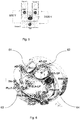
- placing catheter tip electrodes into the proximal regions of both left and right coronary arteries also allows electroporation of the aortic root ganglionated plexi ( Fig. 6 )..
- using three catheter tip electrodes as described for Examples 4 to 6 above may also be utilised to create additional electrode field shapes, all intersecting and ablating the aortic root ganglionated plexi.
- a voltage of 1000 Volts may be needed, with an operational range for the apparatus of 500- 2000 Volts, being applied at a pulse duration of 100 microseconds, with an operational range of 1 microsecond to 1 millisecond.
- the resulting electroporation field strength will be in the region of 1000 Volts per centimetre depending on anatomical variations and positioning of the respective catheter tips. Multiple repeat pulses would be used, all pulses being monophasic. Such a region of field strength is anticipated to provide an operating zone that is primarily in the regime of reversible electroporation for myocardial tissue, but irreversible for ganglia structures in the fat pads..
- a catheter tip and electrode assembly may be sheathed using a sheath having single or multiple apertures the size and shape of which may be the same or different.
- a circular aperture 70 in a sheath 71 is illustrated, and the sheath 71 would be moveable upon a catheter (not shown) axially and rotationally with respect to the longitudinal axis of the catheter so as to be fully or partially aligned with an electrode on the catheter tip to adjust electrical field emission.
- a rectangular aperture 72 in a sheath 73 is illustrated, and the sheath 73 would be moveable upon a catheter (not shown) axially and rotationally with respect to the longitudinal axis of the catheter by a user so as to be fully or partially aligned with an electrode on the catheter tip to adjust electrical field emission.
- a rectangular aperture 72 in a sheath 73 is illustrated, and the sheath is shown overlying a catheter tip and electrode assembly 75 such that the rectangular aperture or "window" is aligned with an electrode 76 on the catheter tip to allow electrical field emission.
- the relative movement of the sheath with respect to the catheter can be achieved by a user manipulating a proximal handle of the catheter and/or a gripping portion of the overlying sheath.
- the sheath may be a metal braided sheath as illustrated in Fig. 11 wherein a metal cellular pattern structure 77 serves as a Faraday cage concealed within a polymeric casing 78 of the sheath.
- the metal may be of any suitable conductive material such a conductive metal or alloy, for example copper, stainless steel or a nickel-titanium alloy (nitinol).
- a suitable catheter has a throughbore through which electrical conductor wires can be passed to connect with the respective electrodes in the illustrated embodiments.
- a straight linear catheter tip 81 has spaced apart electrodes 83 attached to the catheter tip,
- a bifurcated linear catheter tip 82 I shown which has spaced apart electrodes 84, 84' on the respective limbs of the bifurcated catheter tip 82.
- a loop type, curvilinear catheter tip 85 bearing spaced electrodes 86 is illustrated in Fig. 15 .
- Each of the electrodes can be selectively controlled to operate together or individually in a sequence and at varying electrical field output.
- an electrode configured to fit over a catheter tip may be of a tubular form 90 with an irrigation hole 91 to allow through flow of a fluid.
- the fluid may be introduced through a hollow catheter introduced to a throughbore 100 of electrode of the tubular form 90, and having a corresponding aperture to register with the irrigation hole 91.
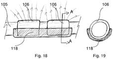
- Fig. 18 illustrates schematically a portion of a catheter tip and electrode assembly which is partially insulated, the catheter 105 bearing two spaced electrodes 106 each partially covered by an insulator 118, optionally the insulator 118 being a portion of an inflatable envelope or "balloon"; and Fig. 19 shows a cross-section [A-A] of the insulated electrode bearing potion of the catheter tip and electrode assembly
- an epicardial fat pad with ganglia is represented undergoing simultaneous temperature treatments such that by application of heat on the epicardial side, heating of the fat pad is achieved, and by application of cooling on the endocardial side, cooling of the myocardium is achieved.
- heating of the fat pad is achieved, and by application of cooling on the endocardial side, cooling of the myocardium is achieved.
- the ganglia become more susceptible to electroporation and thus can be targeted at a lower electrical field strength, which mitigates the risk of unintended damage to the myocardium. This risk of unintended damage is still further managed by introducing cooling of the myocardium tissue surface.
- Cooling of the myocardium is achievable by introducing a chilled saline balloon, whereby the temperature of the myocardium may be cooled locally to about 5-30 °C.
- Heating of the fat pad is achievable by introducing a warm saline-containing balloon to overlie and contact the fat pad.
- an electroporation apparatus including a bipolar catheter tip-electrode assembly may be introduced to contact epicardial tissue at spaced locations such that a (+) electrode of the catheter tip-electrode assembly is applied to the epicardial tissue or fat pad in the vicinity of the ganglia, and a (-) electrode is also applied to a different area of the epicardial tissue or fat pad in the vicinity of the ganglia ( Fig. 8 ), the electrodes being connected to a D.C. source for effecting electroporation by means of an electrical field extending over the epicardial surface between the electrodes.
- an electrode for example (+) electrode of the catheter tip-electrode assembly is introduced to contact epicardial tissue at a selected location of the epicardial tissue or fat pad in the vicinity of the ganglia, and another electrode of opposite polarity, in this example (-) electrode of the catheter tip-electrode assembly is introduced to contact myocardial tissue in the vicinity of the ganglia, the electrodes being connected to a D.C. source for effecting electroporation by means of an electrical field extending through the myocardium between the electrodes.
- An electroporation apparatus suitable for carrying out the procedure including temperature treatments comprises an elongate tubular catheter having a proximal end and a distal end, and internal fluid channels.
- the distal end of the catheter has spaced electrodes on a side surface, and a recess between the electrodes.
- the recess houses an inflatable balloon in communication with the internal fluid channels for receiving and venting a temperature control fluid, such as heated or cooled saline which may be circulated under pressure.
- Electrical conductor wires located upon or within the elongate tubular catheter are connectable to an external direct current supply with controller to adjust the voltage of the electrical supply.
- the inflatable balloon for receiving a temperature controlled fluid is housed in a distal end face recess, instead of in a side surface of the elongate tubular catheter.
- a unipolar electroporation apparatus has a single distal end electrode connected to a direct current electrical supply.
- a single electrode When used in a unipolar manner a single electrode would be used in conjunction with a back pad/dispersive electrode of opposite polarity on the patient (sometimes called an "indifferent electrode").
- Still further embodiments of the enhanced electroporation apparatus using differing combinations of electrodes, e.g. three electrodes as disclosed in Example 4 above are contemplated, and whilst examples are provided by way of illustration, it will be appreciated that these are indicative designs and that other designs with different overall shape and electrode arrangements are possible, so that these examples are non-limiting and attention is directed to the scope of the claims hereinafter appearing.
Landscapes
- Health & Medical Sciences (AREA)
- Life Sciences & Earth Sciences (AREA)
- Surgery (AREA)
- Engineering & Computer Science (AREA)
- Plasma & Fusion (AREA)
- Medical Informatics (AREA)
- Otolaryngology (AREA)
- Physics & Mathematics (AREA)
- Cardiology (AREA)
- Biomedical Technology (AREA)
- Heart & Thoracic Surgery (AREA)
- Nuclear Medicine, Radiotherapy & Molecular Imaging (AREA)
- Molecular Biology (AREA)
- Animal Behavior & Ethology (AREA)
- General Health & Medical Sciences (AREA)
- Public Health (AREA)
- Veterinary Medicine (AREA)
- Surgical Instruments (AREA)
Priority Applications (4)
| Application Number | Priority Date | Filing Date | Title |
|---|---|---|---|
| EP17192463.2A EP3459480A1 (fr) | 2017-09-21 | 2017-09-21 | Appareil permettant de localiser un champ électrique |
| PCT/EP2018/075075 WO2019057665A1 (fr) | 2017-09-21 | 2018-09-17 | Appareil pour localiser un champ électrique |
| EP18765933.9A EP3684278B1 (fr) | 2017-09-21 | 2018-09-17 | Appareil permettant de localiser un champ électrique |
| US16/647,831 US20200275973A1 (en) | 2017-09-21 | 2018-09-17 | Apparatus for localising an electrical field |
Applications Claiming Priority (1)
| Application Number | Priority Date | Filing Date | Title |
|---|---|---|---|
| EP17192463.2A EP3459480A1 (fr) | 2017-09-21 | 2017-09-21 | Appareil permettant de localiser un champ électrique |
Publications (1)
| Publication Number | Publication Date |
|---|---|
| EP3459480A1 true EP3459480A1 (fr) | 2019-03-27 |
Family
ID=59930263
Family Applications (2)
| Application Number | Title | Priority Date | Filing Date |
|---|---|---|---|
| EP17192463.2A Withdrawn EP3459480A1 (fr) | 2017-09-21 | 2017-09-21 | Appareil permettant de localiser un champ électrique |
| EP18765933.9A Active EP3684278B1 (fr) | 2017-09-21 | 2018-09-17 | Appareil permettant de localiser un champ électrique |
Family Applications After (1)
| Application Number | Title | Priority Date | Filing Date |
|---|---|---|---|
| EP18765933.9A Active EP3684278B1 (fr) | 2017-09-21 | 2018-09-17 | Appareil permettant de localiser un champ électrique |
Country Status (3)
| Country | Link |
|---|---|
| US (1) | US20200275973A1 (fr) |
| EP (2) | EP3459480A1 (fr) |
| WO (1) | WO2019057665A1 (fr) |
Cited By (5)
| Publication number | Priority date | Publication date | Assignee | Title |
|---|---|---|---|---|
| RU2764828C1 (ru) * | 2020-07-28 | 2022-01-21 | Байосенс Вебстер (Изрэйл) Лтд. | Управление абляцией при необратимой электропорации с использованием фокального катетера, имеющего датчики усилия контакта и температуры |
| EP4212120A1 (fr) * | 2022-01-12 | 2023-07-19 | AtriAN Medical Limited | Dispositif d'ablation électrique |
| US11786300B2 (en) | 2021-04-07 | 2023-10-17 | Btl Medical Technologies S.R.O. | Pulsed field ablation device and method |
| US11896298B2 (en) | 2021-07-06 | 2024-02-13 | Btl Medical Development A.S. | Pulsed field ablation device and method |
| US12076067B2 (en) | 2022-10-05 | 2024-09-03 | Btl Medical Development A.S. | Pulsed field ablation device and method |
Families Citing this family (7)
| Publication number | Priority date | Publication date | Assignee | Title |
|---|---|---|---|---|
| US12403305B2 (en) | 2016-06-27 | 2025-09-02 | Galvanize Therapeutics, Inc. | Immunostimulation in the treatment of viral infection |
| EP3474760B1 (fr) | 2016-06-27 | 2023-01-11 | Galvanize Therapeutics, Inc. | Générateur et un cathéter avec une électrode pour traiter une voie pulmonaire |
| DK3731771T3 (da) | 2017-12-26 | 2023-08-28 | Galvanize Therapeutics Inc | V462033dk00 |
| CN118203401A (zh) * | 2019-04-18 | 2024-06-18 | 盖能适治疗股份有限公司 | 用于治疗异常组织的装置、系统和方法 |
| US11540877B2 (en) * | 2019-12-03 | 2023-01-03 | Biosense Webster (Israel) Ltd. | Pulse generator for irreversible electroporation |
| US12076071B2 (en) | 2020-08-14 | 2024-09-03 | Kardium Inc. | Systems and methods for treating tissue with pulsed field ablation |
| US20240299091A1 (en) * | 2021-05-20 | 2024-09-12 | The Trustees Of Dartmouth College | Radial Pulse Field Ablation Catheter System |
Citations (7)
| Publication number | Priority date | Publication date | Assignee | Title |
|---|---|---|---|---|
| EP1077048A2 (fr) * | 1999-08-16 | 2001-02-21 | Hans-Jürgen Dipl.-Ing. Bisping | Arrangement des électrodes pour un cathéter médical |
| US20020040204A1 (en) | 1996-06-24 | 2002-04-04 | Dev Nagendu B. | Electroporation-enhanced inhibition of vascular neointimal hyperplasia |
| US6635047B2 (en) | 2001-08-06 | 2003-10-21 | Scimed Life Systems, Inc. | Integrated polymer and braid for intravascular catheters |
| US20060265014A1 (en) * | 2002-04-08 | 2006-11-23 | Ardian, Inc. | Methods and apparatus for bilateral renal neuromodulation |
| US20130030430A1 (en) * | 2011-07-29 | 2013-01-31 | Stewart Mark T | Intracardiac tools and methods for delivery of electroporation therapies |
| EP2986243A1 (fr) | 2013-04-15 | 2016-02-24 | Mayo Foundation for Medical Education and Research | Procédé et appareil pour l'ablation épicardique, par voie percutanée et sans lésion myocardique, de plexus cardiaques ganglionnés |
| WO2017024123A1 (fr) * | 2015-08-06 | 2017-02-09 | Medtronic, Inc. | Ablation de tissu cardiaque par champ pulsé |
Family Cites Families (4)
| Publication number | Priority date | Publication date | Assignee | Title |
|---|---|---|---|---|
| US20050261672A1 (en) * | 2004-05-18 | 2005-11-24 | Mark Deem | Systems and methods for selective denervation of heart dysrhythmias |
| CN105979896A (zh) * | 2014-02-11 | 2016-09-28 | 圣犹达医疗用品心脏病学部门有限公司 | 消融导管和相关联的方法 |
| WO2015175944A1 (fr) * | 2014-05-16 | 2015-11-19 | Gary Long | Méthodes et appareil d'ablation tissulaire à plusieurs cathéters |
| US10172673B2 (en) * | 2016-01-05 | 2019-01-08 | Farapulse, Inc. | Systems devices, and methods for delivery of pulsed electric field ablative energy to endocardial tissue |
-
2017
- 2017-09-21 EP EP17192463.2A patent/EP3459480A1/fr not_active Withdrawn
-
2018
- 2018-09-17 EP EP18765933.9A patent/EP3684278B1/fr active Active
- 2018-09-17 WO PCT/EP2018/075075 patent/WO2019057665A1/fr not_active Ceased
- 2018-09-17 US US16/647,831 patent/US20200275973A1/en not_active Abandoned
Patent Citations (8)
| Publication number | Priority date | Publication date | Assignee | Title |
|---|---|---|---|---|
| US20020040204A1 (en) | 1996-06-24 | 2002-04-04 | Dev Nagendu B. | Electroporation-enhanced inhibition of vascular neointimal hyperplasia |
| EP1077048A2 (fr) * | 1999-08-16 | 2001-02-21 | Hans-Jürgen Dipl.-Ing. Bisping | Arrangement des électrodes pour un cathéter médical |
| US6635047B2 (en) | 2001-08-06 | 2003-10-21 | Scimed Life Systems, Inc. | Integrated polymer and braid for intravascular catheters |
| US20060265014A1 (en) * | 2002-04-08 | 2006-11-23 | Ardian, Inc. | Methods and apparatus for bilateral renal neuromodulation |
| US20130030430A1 (en) * | 2011-07-29 | 2013-01-31 | Stewart Mark T | Intracardiac tools and methods for delivery of electroporation therapies |
| US20160051324A1 (en) | 2011-07-29 | 2016-02-25 | Medtronic Ablation Frontiers Llc | Intracardiac tools and methods for delivery of electroporation therapies |
| EP2986243A1 (fr) | 2013-04-15 | 2016-02-24 | Mayo Foundation for Medical Education and Research | Procédé et appareil pour l'ablation épicardique, par voie percutanée et sans lésion myocardique, de plexus cardiaques ganglionnés |
| WO2017024123A1 (fr) * | 2015-08-06 | 2017-02-09 | Medtronic, Inc. | Ablation de tissu cardiaque par champ pulsé |
Non-Patent Citations (6)
| Title |
|---|
| LO ET AL., HEART RHYTHM, vol. 10, no. 5, 2013, pages 751 - 757 |
| LU ET AL., JOURNAL OF CARDIOVASCULAR ELECTROPHYSIOLOGY, vol. 21, no. 12, 2010, pages 1392 - 1399 |
| R LEMERY ET AL., HEART RHYTHM, vol. 14, no. 1, 2017, pages 128 - 132 |
| RB KROL ET AL., JOURNAL OF INTERVENTIONAL CARDIAC ELECTROPHYSIOLOGY, vol. 3, 1999, pages 19 - 25 |
| TUNG ET AL., CIRCULATION RESEARCH, 1991 |
| WANG ET AL., JOURNAL OF THE AMERICAN COLLEGE OF CARDIOLOGY, vol. 1, 2015, pages 390 - 397 |
Cited By (8)
| Publication number | Priority date | Publication date | Assignee | Title |
|---|---|---|---|---|
| RU2764828C1 (ru) * | 2020-07-28 | 2022-01-21 | Байосенс Вебстер (Изрэйл) Лтд. | Управление абляцией при необратимой электропорации с использованием фокального катетера, имеющего датчики усилия контакта и температуры |
| EP3944830A1 (fr) | 2020-07-28 | 2022-02-02 | Biosense Webster (Israel) Ltd | Contrôle de l'ablation par électroporation irréversible à l'aide d'un cathéter focal doté de capteurs de force de contact et de température |
| US11786300B2 (en) | 2021-04-07 | 2023-10-17 | Btl Medical Technologies S.R.O. | Pulsed field ablation device and method |
| US11832785B2 (en) | 2021-04-07 | 2023-12-05 | Btl Medical Development A.S. | Pulsed field ablation device and method |
| US11896298B2 (en) | 2021-07-06 | 2024-02-13 | Btl Medical Development A.S. | Pulsed field ablation device and method |
| EP4212120A1 (fr) * | 2022-01-12 | 2023-07-19 | AtriAN Medical Limited | Dispositif d'ablation électrique |
| US12076067B2 (en) | 2022-10-05 | 2024-09-03 | Btl Medical Development A.S. | Pulsed field ablation device and method |
| US12279801B2 (en) | 2022-10-05 | 2025-04-22 | Btl Medical Development A.S. | Pulsed field ablation device and method |
Also Published As
| Publication number | Publication date |
|---|---|
| EP3684278A1 (fr) | 2020-07-29 |
| EP3684278B1 (fr) | 2024-06-05 |
| US20200275973A1 (en) | 2020-09-03 |
| WO2019057665A1 (fr) | 2019-03-28 |
| EP3684278C0 (fr) | 2024-06-05 |
Similar Documents
| Publication | Publication Date | Title |
|---|---|---|
| EP3684278B1 (fr) | Appareil permettant de localiser un champ électrique | |
| EP3801327B1 (fr) | Appareil d'électrophysiologie | |
| US20220338925A1 (en) | Enhanced electroporation of cardiac tissue | |
| US10987163B2 (en) | Treatment of atrial fibrillation using high-frequency pacing and ablation of renal nerves | |
| US6217576B1 (en) | Catheter probe for treating focal atrial fibrillation in pulmonary veins | |
| US6308091B1 (en) | Mapping and ablation catheter system | |
| US5687723A (en) | Mapping and ablation catheter system | |
| JP6301926B2 (ja) | カテーテル、カテーテルシステム、及び組織構造を刺通する方法 | |
| US20050010095A1 (en) | Multi-purpose catheter apparatus and method of use | |
| EP4134031B1 (fr) | Systèmes d'électroporation à l'aide de formes d'ondes asymétriques et de formes d'ondes à durée de rafale réduite | |
| US20160113711A1 (en) | Ablation catheter and method of forming a circular lesion | |
| CN119836310A (zh) | 锁骨下动脉周围去神经支配的系统和方法 | |
| EP4626348A2 (fr) | Dispositifs de cathéter multifonctionnel et méthodes de diagnostic et de traitement d'affections cardiaques | |
| GB2347084A (en) | Ablation lead with screw tip | |
| WO2025222080A1 (fr) | Dispositifs médicaux conçus pour une électroporation thérapeutique à température régulée |
Legal Events
| Date | Code | Title | Description |
|---|---|---|---|
| PUAI | Public reference made under article 153(3) epc to a published international application that has entered the european phase |
Free format text: ORIGINAL CODE: 0009012 |
|
| STAA | Information on the status of an ep patent application or granted ep patent |
Free format text: STATUS: THE APPLICATION HAS BEEN PUBLISHED |
|
| AK | Designated contracting states |
Kind code of ref document: A1 Designated state(s): AL AT BE BG CH CY CZ DE DK EE ES FI FR GB GR HR HU IE IS IT LI LT LU LV MC MK MT NL NO PL PT RO RS SE SI SK SM TR |
|
| AX | Request for extension of the european patent |
Extension state: BA ME |
|
| STAA | Information on the status of an ep patent application or granted ep patent |
Free format text: STATUS: THE APPLICATION IS DEEMED TO BE WITHDRAWN |
|
| 18D | Application deemed to be withdrawn |
Effective date: 20190928 |