EP3459656A1 - Procédé et dispositif de fabrication additive d'un composant - Google Patents
Procédé et dispositif de fabrication additive d'un composant Download PDFInfo
- Publication number
- EP3459656A1 EP3459656A1 EP18195228.4A EP18195228A EP3459656A1 EP 3459656 A1 EP3459656 A1 EP 3459656A1 EP 18195228 A EP18195228 A EP 18195228A EP 3459656 A1 EP3459656 A1 EP 3459656A1
- Authority
- EP
- European Patent Office
- Prior art keywords
- component
- working space
- temperature
- layer
- melting
- Prior art date
- Legal status (The legal status is an assumption and is not a legal conclusion. Google has not performed a legal analysis and makes no representation as to the accuracy of the status listed.)
- Withdrawn
Links
Images

Classifications
-
- B—PERFORMING OPERATIONS; TRANSPORTING
- B22—CASTING; POWDER METALLURGY
- B22F—WORKING METALLIC POWDER; MANUFACTURE OF ARTICLES FROM METALLIC POWDER; MAKING METALLIC POWDER; APPARATUS OR DEVICES SPECIALLY ADAPTED FOR METALLIC POWDER
- B22F3/00—Manufacture of workpieces or articles from metallic powder characterised by the manner of compacting or sintering; Apparatus specially adapted therefor ; Presses and furnaces
- B22F3/10—Sintering only
- B22F3/1017—Multiple heating or additional steps
- B22F3/1028—Controlled cooling
-
- B—PERFORMING OPERATIONS; TRANSPORTING
- B22—CASTING; POWDER METALLURGY
- B22F—WORKING METALLIC POWDER; MANUFACTURE OF ARTICLES FROM METALLIC POWDER; MAKING METALLIC POWDER; APPARATUS OR DEVICES SPECIALLY ADAPTED FOR METALLIC POWDER
- B22F10/00—Additive manufacturing of workpieces or articles from metallic powder
- B22F10/20—Direct sintering or melting
- B22F10/28—Powder bed fusion, e.g. selective laser melting [SLM] or electron beam melting [EBM]
-
- B—PERFORMING OPERATIONS; TRANSPORTING
- B22—CASTING; POWDER METALLURGY
- B22F—WORKING METALLIC POWDER; MANUFACTURE OF ARTICLES FROM METALLIC POWDER; MAKING METALLIC POWDER; APPARATUS OR DEVICES SPECIALLY ADAPTED FOR METALLIC POWDER
- B22F3/00—Manufacture of workpieces or articles from metallic powder characterised by the manner of compacting or sintering; Apparatus specially adapted therefor ; Presses and furnaces
- B22F3/24—After-treatment of workpieces or articles
-
- B—PERFORMING OPERATIONS; TRANSPORTING
- B29—WORKING OF PLASTICS; WORKING OF SUBSTANCES IN A PLASTIC STATE IN GENERAL
- B29C—SHAPING OR JOINING OF PLASTICS; SHAPING OF MATERIAL IN A PLASTIC STATE, NOT OTHERWISE PROVIDED FOR; AFTER-TREATMENT OF THE SHAPED PRODUCTS, e.g. REPAIRING
- B29C64/00—Additive manufacturing, i.e. manufacturing of three-dimensional [3D] objects by additive deposition, additive agglomeration or additive layering, e.g. by 3D printing, stereolithography or selective laser sintering
- B29C64/10—Processes of additive manufacturing
- B29C64/141—Processes of additive manufacturing using only solid materials
- B29C64/153—Processes of additive manufacturing using only solid materials using layers of powder being selectively joined, e.g. by selective laser sintering or melting
-
- B—PERFORMING OPERATIONS; TRANSPORTING
- B33—ADDITIVE MANUFACTURING TECHNOLOGY
- B33Y—ADDITIVE MANUFACTURING, i.e. MANUFACTURING OF THREE-DIMENSIONAL [3D] OBJECTS BY ADDITIVE DEPOSITION, ADDITIVE AGGLOMERATION OR ADDITIVE LAYERING, e.g. BY 3D PRINTING, STEREOLITHOGRAPHY OR SELECTIVE LASER SINTERING
- B33Y10/00—Processes of additive manufacturing
-
- B—PERFORMING OPERATIONS; TRANSPORTING
- B33—ADDITIVE MANUFACTURING TECHNOLOGY
- B33Y—ADDITIVE MANUFACTURING, i.e. MANUFACTURING OF THREE-DIMENSIONAL [3D] OBJECTS BY ADDITIVE DEPOSITION, ADDITIVE AGGLOMERATION OR ADDITIVE LAYERING, e.g. BY 3D PRINTING, STEREOLITHOGRAPHY OR SELECTIVE LASER SINTERING
- B33Y30/00—Apparatus for additive manufacturing; Details thereof or accessories therefor
-
- B—PERFORMING OPERATIONS; TRANSPORTING
- B33—ADDITIVE MANUFACTURING TECHNOLOGY
- B33Y—ADDITIVE MANUFACTURING, i.e. MANUFACTURING OF THREE-DIMENSIONAL [3D] OBJECTS BY ADDITIVE DEPOSITION, ADDITIVE AGGLOMERATION OR ADDITIVE LAYERING, e.g. BY 3D PRINTING, STEREOLITHOGRAPHY OR SELECTIVE LASER SINTERING
- B33Y50/00—Data acquisition or data processing for additive manufacturing
- B33Y50/02—Data acquisition or data processing for additive manufacturing for controlling or regulating additive manufacturing processes
-
- B—PERFORMING OPERATIONS; TRANSPORTING
- B22—CASTING; POWDER METALLURGY
- B22F—WORKING METALLIC POWDER; MANUFACTURE OF ARTICLES FROM METALLIC POWDER; MAKING METALLIC POWDER; APPARATUS OR DEVICES SPECIALLY ADAPTED FOR METALLIC POWDER
- B22F10/00—Additive manufacturing of workpieces or articles from metallic powder
- B22F10/60—Treatment of workpieces or articles after build-up
- B22F10/64—Treatment of workpieces or articles after build-up by thermal means
-
- B—PERFORMING OPERATIONS; TRANSPORTING
- B22—CASTING; POWDER METALLURGY
- B22F—WORKING METALLIC POWDER; MANUFACTURE OF ARTICLES FROM METALLIC POWDER; MAKING METALLIC POWDER; APPARATUS OR DEVICES SPECIALLY ADAPTED FOR METALLIC POWDER
- B22F12/00—Apparatus or devices specially adapted for additive manufacturing; Auxiliary means for additive manufacturing; Combinations of additive manufacturing apparatus or devices with other processing apparatus or devices
- B22F12/20—Cooling means
-
- B—PERFORMING OPERATIONS; TRANSPORTING
- B22—CASTING; POWDER METALLURGY
- B22F—WORKING METALLIC POWDER; MANUFACTURE OF ARTICLES FROM METALLIC POWDER; MAKING METALLIC POWDER; APPARATUS OR DEVICES SPECIALLY ADAPTED FOR METALLIC POWDER
- B22F3/00—Manufacture of workpieces or articles from metallic powder characterised by the manner of compacting or sintering; Apparatus specially adapted therefor ; Presses and furnaces
- B22F3/24—After-treatment of workpieces or articles
- B22F2003/248—Thermal after-treatment
-
- B—PERFORMING OPERATIONS; TRANSPORTING
- B22—CASTING; POWDER METALLURGY
- B22F—WORKING METALLIC POWDER; MANUFACTURE OF ARTICLES FROM METALLIC POWDER; MAKING METALLIC POWDER; APPARATUS OR DEVICES SPECIALLY ADAPTED FOR METALLIC POWDER
- B22F2999/00—Aspects linked to processes or compositions used in powder metallurgy
-
- B—PERFORMING OPERATIONS; TRANSPORTING
- B29—WORKING OF PLASTICS; WORKING OF SUBSTANCES IN A PLASTIC STATE IN GENERAL
- B29C—SHAPING OR JOINING OF PLASTICS; SHAPING OF MATERIAL IN A PLASTIC STATE, NOT OTHERWISE PROVIDED FOR; AFTER-TREATMENT OF THE SHAPED PRODUCTS, e.g. REPAIRING
- B29C64/00—Additive manufacturing, i.e. manufacturing of three-dimensional [3D] objects by additive deposition, additive agglomeration or additive layering, e.g. by 3D printing, stereolithography or selective laser sintering
- B29C64/30—Auxiliary operations or equipment
- B29C64/364—Conditioning of environment
-
- Y—GENERAL TAGGING OF NEW TECHNOLOGICAL DEVELOPMENTS; GENERAL TAGGING OF CROSS-SECTIONAL TECHNOLOGIES SPANNING OVER SEVERAL SECTIONS OF THE IPC; TECHNICAL SUBJECTS COVERED BY FORMER USPC CROSS-REFERENCE ART COLLECTIONS [XRACs] AND DIGESTS
- Y02—TECHNOLOGIES OR APPLICATIONS FOR MITIGATION OR ADAPTATION AGAINST CLIMATE CHANGE
- Y02P—CLIMATE CHANGE MITIGATION TECHNOLOGIES IN THE PRODUCTION OR PROCESSING OF GOODS
- Y02P10/00—Technologies related to metal processing
- Y02P10/25—Process efficiency
Definitions
- the present invention relates to a method for the additive production of a component. Furthermore, the present invention relates to a device for the additive production of a component, which is designed for carrying out the method.
- additive manufacturing processes such as 3D printing processes
- 3D printing processes are becoming increasingly important as they have significant advantages in terms of freedom of shaping, near net shape, flexibility and speed over conventional manufacturing processes, which often include operations such as sawing, milling, turning, welding, gluing, screwing or the like ,
- a well-known additive manufacturing process is selective laser melting or selective laser melting, which is also referred to as SLM process.
- SLM method as well as in some other additive manufacturing methods, a material layer of a component material is first provided on a working space floor, in particular as a material layer with a constant layer thickness.
- the component material has, for example, a powder or granular form and is evenly distributed on the working space floor, in particular by means of doctoring.
- the component material is selectively or locally selectively melted by means of a melting device or at least selectively or selectively sintered locally.
- the targeted melting or targeted sintering creates a coherent structure of a component layer of the component.
- Targeted melting or targeted sintering is a central feature of many additive processes.
- local melting also has material-related or metallographic disadvantages.
- the component structure produced essentially corresponds to a welded structure that has been produced with a high cooling rate, since in each case only small areas are melted and the molten areas are cooled particularly rapidly via the adjacent cooler component material.
- High cooling rates or such component structures are a disadvantage, in particular for heat-resistant or hot-crack-sensitive materials, since the components produced often have an increased brittleness and particularly favor a disadvantageous crack formation by which, in particular, a mechanical load-bearing capacity of the component can be considerably reduced.
- the object is achieved by a method for the additive production of a component according to independent claim 1. Furthermore, the above object is achieved by a device for the additive production of a component according to independent claim 9. Further features and details of the invention will become apparent from the dependent claims, the description and the drawings. In this case, features and details that are described in connection with the inventive method for the additive production of a component, of course, also in connection with the inventive device for the additive production of a component and in each case vice versa, so taken with respect to the disclosure of the individual invention aspects always reciprocal reference will or can become.
- the working space floor is the basis for the additive manufacturing of the component.
- the working space floor is designed such that the component material can be provided thereon and can be distributed to a material layer, in particular a material layer with a constant or essentially constant material layer thickness.
- the provision of the material layer takes place by means of the layer application device, wherein the material layer is preferably provided as a material layer with a constant or essentially constant layer thickness.
- the provision of the material layer can take place, for example, by deliberate depositing and / or doctoring by means of the layer application device.
- provision may be made for a plurality of component materials to be used for a component layer or different component layers. In the case of different component materials, it is preferred that the different component materials have the same or at least a similar melting point in order to ensure a good bonding of the various component materials by the targeted melting.
- Different component materials are particularly advantageous if a component is to be produced which has different component properties, wherein these different component properties are not or only with great effort achieved by a targeted process control, such as temperature control, atmosphere influencing or the like.
- the provision of the material layer with different component materials can be carried out, for example, by means of a corresponding powder mixture or by application, in particular targeted application, of a plurality of powders of different component materials.
- the component material is arranged on the provision of an existing object in order to enter into a material connection during targeted melting with this object or to embed the object in the component material and thus to hold it in a form-fitting manner.
- energy is selectively introduced into at least one predetermined area of the material layer in order to melt this area or at least to sinter it.
- a plurality of areas are melted, which may be interconnected or separated from each other.
- the introduction of the energy can be done for example by means of a laser beam and / or an electron beam or the like.
- the component material of a molten region forms a cohesive material unit by binding the individual granulate or powder constituents of the component material together.
- the material unit After the subsequent solidification of the molten component material, the material unit has a dimensional stability. In this way, a component material layer has been produced.
- the working space bottom is preferably lowered by a layer thickness of the produced component material layer in order to promote the provision and targeted melting of a following material layer.
- a further material layer and targeted melting of the further material layer it is possible to produce a further component layer, which is materially connected to the previous component layer.
- the at least one first Temper michsselltes is performed in addition to the targeted melting or sintering in the working space and at the at least one first component site. It can be provided according to the invention that the at least one first tempering measure is directed to a plurality of first component locations or the complete component. Furthermore, the at least one first tempering measure can be carried out in such a way that different first component locations or the complete component are influenced differently.
- the first Temper michsdorfdging for example, during or after the targeted melting of the provided material layer or the generation of a component layer done. It can be provided according to the invention that the first tempering measure is performed in such a way that in this way several component layers are influenced.
- the first tempering measure is preferably carried out at component locations at which the component has high notch effects or an unfavorable stress distribution structurally conditioned in order to improve the mechanical properties of the component at these particularly endangered component sites.
- the first tempering measure is preferably carried out such that component properties of the at least one first component location of the component are selectively modified.
- the component properties relate, for example, to the microstructure, the microstructure, the crystal structure, the residual stress or deformation state, crystal growth or the like.
- the properties of the connection of the different component materials can also be selectively influenced by means of the first temperature control measure, for example diffusion depth, crystal growth, microstructure composite or the like.
- An inventive method has over conventional methods for the additive production of a component has the advantage that with simple means and cost, a component can be produced additively, which has at least partially improved component properties.
- the tensile strength and / or compressive strength and / or notched impact strength of the additive-produced component can be improved.
- a preferred embodiment of the invention may be provided in a method that is carried out as at least one first Temper michssell Vietnamese a targeted local heat input or targeted local heat removal at the at least one first component site.
- heat for example, a solution annealing, diffusion annealing, tempering or the like can be effected. It can be achieved according to the invention also a re-melting of the at least one first component site.
- the at least one first Temper michsdorfdging intensity and / or duration of action are selectively controlled so as to influence, for example, the penetration depth of a warming.
- a targeted local heat removal for example, a compensation or a quenching process can be achieved.
- a local heat removal is, for example, by local inflow of a cooling gas or a process-compatible cooling medium, such as injection of a vaporizable water mist, away from the melting area, feasible.
- the at least one first tempering measure is carried out such that a temperature gradient of at least one second component location of a component layer is influenced differently than the temperature gradient of the at least one first component location.
- no interference an indirect influence on the heat conduction of the component or a direct influence, which deliberately different than the direct influence of the first component site is educated, understood. This has the advantage that the additive production of a component which has component regions with specifically different material properties is improved.
- At least one second Temper istssell Spotify is performed in the working space such that the working space is uniformly or substantially uniformly tempered.
- the entire working space or only a portion of the working space can be influenced.
- heat is preferably introduced into the working space.
- the heat is generated for example by means of a heater.
- the heat input is preferably for increasing or maintaining a component temperature. It may be provided according to the invention that a cooling rate of the component is reduced by the introduction of heat. In this way, short- or medium-term heat treatments or a trace heating of the melting process are possible, as it is advantageous, for example, for materials susceptible to hot cracking. Also, in this way cooling-related residual stresses can be reduced.
- the temperature and / or the temperature gradient of the at least one first component location is determined by means of a temperature detection device, wherein the at least one first temperature control measure is controlled as a function of the determined temperature and / or the determined temperature gradient of the at least one first component location.
- the temperature sensing device is preferably designed as an infrared thermometer or camera.
- the temperature detection device is also designed to determine an internal temperature of the working space.
- a temperature distribution of the at least one first component layer is determined by means of the temperature detection device.
- the at least one second tempering measure is controlled as a function of the determined temperature gradient of the at least one first component location.
- the control of the first Temper istsdorflite is taken into account.
- the temperature gradients of the other component sites of the component can be selectively influenced via an improved control of the second tempering measure and can be tuned to the temperature gradient of the first component location.
- sudden component structure changes in the component can be avoided or at least significantly reduced.
- component properties of the component can be further improved.
- the working space for influencing the generation of at least one component layer is acted upon by means of an atmosphere control device with a protective gas and / or charged with an active gas and / or fully or partially evacuated.
- a shielding gas By means of a shielding gas, a safe process control can be achieved, so that unwanted chemical effects on the component material during melting can be avoided.
- an active gas By means of an active gas, a targeted reaction with the component material, in particular with the component material located in the molten state, can be effected. In this way, for example, an oxidation of the Induceable component material, by means of which contamination of the component material can be eliminated. Under a vacuum, access of gases to the molten component material is excluded or at least severely restricted.
- melt gas components can escape and be removed.
- the removal of these gas components is preferably carried out by means of the atmosphere control device.
- the object is achieved by a device for the additive production of a component.
- the device has a working space, which is bounded below by a working space floor, a layer application device for providing a material layer of at least one component material in the working space and a melting device for selectively melting the provided material layer for generating a component layer of the component in the working space.
- the device is designed for carrying out the method according to the invention.
- the working space is preferably laterally bounded by a working space wall of the device.
- the working space floor is preferably laterally surrounded by the working space wall and preferably sealed to the working space wall, for example by a sealing strip, in particular made of metal, hard plastic, silicone, rubber or the like.
- the working space floor is preferably movable vertically relative to the working space wall, so that the generation of the component layers can always take place at the same height.
- the device has a working space ceiling, on which components of the device can be arranged. It is further preferred that the working space by means of the working space floor, the working space wall and the working space ceiling is airtight or at least substantially airtight sealable.
- the layer application device is designed to arrange the powdery or granular component material preferably on the working space floor or on an already previously generated component layer to the material layer.
- the layer-applying device can, for example, have a pouring device for pouring the component material as well as a doctor device for uniformly distributing the component material by doctoring.
- the layer application device can have a heating device in order to heat the component material in order to improve processability, in particular fusibility or sinterability, of the component material.
- the melting device is designed for targeted melting of the material layer for generating the component layer of the component.
- predefined molten contours can be generated in the component layer by means of the melting device.
- the melting device preferably has a laser and / or an electron beam device or the like for melting the material layer. It is preferred that the melting device is designed to carry out the first tempering measure.
- the device preferably has a control device which is designed to control the working space bottom, the layer application device and the melting device.
- the control device By means of the control device, the first Temper istsdorflite is controllable.
- the control device is designed to control at least one heating device and / or at least one cooling device of the device.
- the device is designed to carry out the method according to the invention.
- the device according to the invention has the same advantages as already described for the method for the additive production of a component according to the first aspect of the invention. Accordingly, the inventive device for the additive production of a component over conventional devices has the advantage that with simple means and cost, a component can be produced additively, which has at least partially improved component properties. Thus, for example, the tensile strength and / or compressive strength and / or notched impact strength of the additive-produced component can be improved.
- the device has a first tempering device, which is designed to carry out the at least one first tempering measure.
- the first tempering device in this case is a device other than the melting device.
- the first tempering device is designed for heating and / or sintering and / or melting and / or cooling of the component material.
- the control device is designed to control the first temperature control device.
- the first tempering device preferably has a laser and / or an electron beam device and / or a cooling device.
- a first tempering device has the advantage that the temperature or a temperature gradient of defined regions of the component or at least one component layer can be influenced in a targeted manner.
- the device has at least one second tempering device, which is designed as a heating device and / or cooling device.
- the second tempering device is preferably integrated into the working space floor and / or the working space wall and / or the working space ceiling or at least designed for direct tempering of the working space floor and / or the working space wall and / or the work space ceiling.
- the control device is designed to control the second tempering device.
- the second tempering device is coupled to an atmosphere control device and configured to directly heat or cool a gas flow caused by the atmosphere control device.
- the second tempering device is preferably designed to carry out the second tempering measure.
- a second tempering device has the advantage that a temperature in the working space can be controlled by simple means.
- cooling rates of the component are reducible to increase crystal growth and thus increase ductility of the component.
- this cooling rates of the component can be increased in order to shorten the crystal growth and thus to increase the strength of the component.
- the device has at least one temperature detection device for determining the temperature and / or the temperature gradient of the at least one first component location.
- the temperature detection device is preferably designed to detect a temperature distribution on a component layer or a component surface.
- the device comprises at least one atmosphere control device, which is designed to pressurize the working space with a protective gas and / or with an active gas and / or for complete or partial evacuation of the working space.
- An interface of the atmosphere control device and the working space for passing gas is preferably formed in the working space ceiling and / or an upper area of the working space wall.
- the atmosphere control device has at least one nozzle for selectively influencing the atmosphere at a component location of an upper component layer.
- the atmosphere control device is preferably controllable by means of the control device. By the atmosphere control device, an atomic sphere in the working space is selectively controlled or generated. As a result, component properties of the component can be improved.
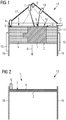
- a preferred embodiment of a device 13 according to the invention is shown schematically in a sectional view.
- the device 13 has a working space 5, which is bounded at the bottom by a working space floor 2, laterally by working space walls 16 and upwards by a working space ceiling 17.
- the working space floor 2 is movable relative to the working space walls 16 in the direction of movement B and counter to the direction of movement B.
- On the working space floor 2, a component 1 is already partially generated.
- the component 1 is surrounded by granular or powdered component material 4.
- the device 13 has a layer application device 6 by means of which the component material 4 in layers in the working space 5 can be introduced.
- a melting device 7 of the device 13 arranged on the working space ceiling 17 is designed to melt or sinter the component material 4 of an upper material layer 3 in a targeted manner to generate a first component layer 9.
- the device 13 has a first tempering device 14, which is arranged on the working space ceiling 17.
- a temperature or a temperature gradient of any first component location 8 of the first component layer 9 can be influenced in a targeted manner by a first tempering measure, e.g. by heating or cooling.
- the first tempering device 14 is designed such that the temperature of a second component location 10 of the first component layer 9 is not influenced or only marginally influenced by the first temperature control measure.
- an atmosphere control device 12 for applying the working space 5 with a protective gas or an active gas and for evacuating the working space 5 is arranged on a working space wall 16.
- a second tempering device 15 is arranged on the working space walls 16, which is designed for heating or cooling the working space walls 16 or of the working space 5, in particular in the context of the second tempering measure.
- a, in particular optical, temperature detecting device 11 for detecting temperatures or temperature gradients of the first component layer 9 is arranged.
- a further temperature detecting device 11 for detecting a temperature of the working space wall 16 and / or a gas in the working space 5 is arranged.
- the temperature detection device 11 is a control of Melting device 7, the first tempering device 14 and the second tempering device 15 can be improved.
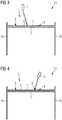
- a first method step of a preferred embodiment of the method according to the invention is shown schematically in a side view.
- a material layer 3 of granular or powdered component material 4 is arranged on the working space floor 2 in the working space 5 by means of the layer application device 6 of the device 13.
- a second process step of a preferred embodiment of the method according to the invention is shown schematically in a side view.
- part of the component material 4 of the material layer 3 is melted by means of the melting device 7 in a targeted manner.
- the molten component material 4 then cools again and solidifies to form a complex. In this way, the first component layer 9 of the component 1 is generated.
- a third method step of a preferred embodiment of the method according to the invention is shown schematically in a side view.
- the first tempering measure is carried out by means of the first tempering device 14.
- heat is introduced into a first component location 8 of the first component layer 9 of the component 1 in order, for example, to increase the temperature of the first component location 8, to hold it or to slow it down.
- the third method step can also take place during the second method step.
- the working space floor 2 is preferably moved downwards in the direction of movement B by a layer thickness of the first component layer 9, so that subsequently the preceding method steps can be repeated. In this way, the component 1 can be produced in layers.
- Fig. 5 shows an exemplary temperature profile of a first component site 8 in the execution of the method according to the invention in a diagram.
- the melting process begins at the first component location 8, in which the component material 4 is melted or sintered.
- the melting process is completed, and the first tempering measure is performed.
- the temperature of the first component location 8 is kept constant by the first temperature control measure until the third time t3, so that, for example, crystal growth is improved.
- the first tempering measure is ended so that the temperature of the first component point 8 drops again more sharply until the fourth point in time t4.
- a first tempering measure and / or a second tempering measure is carried out again in order to keep the temperature of the first component spot 8 constant. From the fifth time t5, the component 1 cools without further targeted temperature effects on the ambient temperature.
- a dashed line shown from the fifth point in time t5 shows an optional first tempering measure in which the first component location 8 is specifically cooled, such as e.g. in a quenching process. Subsequently, the component 1 heats up without further targeted temperature effects on the ambient temperature.
Landscapes
- Engineering & Computer Science (AREA)
- Manufacturing & Machinery (AREA)
- Chemical & Material Sciences (AREA)
- Materials Engineering (AREA)
- Mechanical Engineering (AREA)
- Physics & Mathematics (AREA)
- Optics & Photonics (AREA)
- Plasma & Fusion (AREA)
- Powder Metallurgy (AREA)
Applications Claiming Priority (1)
| Application Number | Priority Date | Filing Date | Title |
|---|---|---|---|
| DE102017216704.1A DE102017216704A1 (de) | 2017-09-21 | 2017-09-21 | Verfahren und Vorrichtung zur additiven Herstellung eines Bauteils |
Publications (1)
| Publication Number | Publication Date |
|---|---|
| EP3459656A1 true EP3459656A1 (fr) | 2019-03-27 |
Family
ID=63642740
Family Applications (1)
| Application Number | Title | Priority Date | Filing Date |
|---|---|---|---|
| EP18195228.4A Withdrawn EP3459656A1 (fr) | 2017-09-21 | 2018-09-18 | Procédé et dispositif de fabrication additive d'un composant |
Country Status (2)
| Country | Link |
|---|---|
| EP (1) | EP3459656A1 (fr) |
| DE (1) | DE102017216704A1 (fr) |
Families Citing this family (2)
| Publication number | Priority date | Publication date | Assignee | Title |
|---|---|---|---|---|
| DE102019121180A1 (de) * | 2019-08-06 | 2021-02-11 | Bayerische Motoren Werke Aktiengesellschaft | Verfahren zur Herstellung eines Bauteils, insbesondere eines Kraftfahrzeugbauteils |
| DE102021101846A1 (de) | 2021-01-27 | 2022-07-28 | Rheinisch-Westfälische Technische Hochschule (RWTH) Aachen, Körperschaft des öffentlichen Rechts | Verfahren für die generative fertigung von bauteilen |
Citations (5)
| Publication number | Priority date | Publication date | Assignee | Title |
|---|---|---|---|---|
| DE102007059865A1 (de) * | 2007-12-12 | 2009-06-18 | Bayerische Motoren Werke Aktiengesellschaft | Verfahren zur Herstellung eines Formkörpers durch schichtweises Aufbauen aus pulverförmigem, metallischen Werkstoff |
| DE102013226298A1 (de) * | 2013-12-17 | 2015-06-18 | MTU Aero Engines AG | Belichtung bei generativer Fertigung |
| WO2015109102A1 (fr) * | 2014-01-20 | 2015-07-23 | United Technologies Corporation | Système de fabrication d'additif utilisant un processus d'épitaxie et procédé de fonctionnement |
| DE102014203711A1 (de) * | 2014-02-28 | 2015-09-03 | MTU Aero Engines AG | Erzeugung von Druckeigenspannungen bei generativer Fertigung |
| DE102014222526A1 (de) * | 2014-11-05 | 2016-05-12 | MTU Aero Engines AG | Verfahren und Vorrichtung zum generativen Herstellen zumindest eines Bauteilbereichs eines Bauteils |
-
2017
- 2017-09-21 DE DE102017216704.1A patent/DE102017216704A1/de not_active Withdrawn
-
2018
- 2018-09-18 EP EP18195228.4A patent/EP3459656A1/fr not_active Withdrawn
Patent Citations (5)
| Publication number | Priority date | Publication date | Assignee | Title |
|---|---|---|---|---|
| DE102007059865A1 (de) * | 2007-12-12 | 2009-06-18 | Bayerische Motoren Werke Aktiengesellschaft | Verfahren zur Herstellung eines Formkörpers durch schichtweises Aufbauen aus pulverförmigem, metallischen Werkstoff |
| DE102013226298A1 (de) * | 2013-12-17 | 2015-06-18 | MTU Aero Engines AG | Belichtung bei generativer Fertigung |
| WO2015109102A1 (fr) * | 2014-01-20 | 2015-07-23 | United Technologies Corporation | Système de fabrication d'additif utilisant un processus d'épitaxie et procédé de fonctionnement |
| DE102014203711A1 (de) * | 2014-02-28 | 2015-09-03 | MTU Aero Engines AG | Erzeugung von Druckeigenspannungen bei generativer Fertigung |
| DE102014222526A1 (de) * | 2014-11-05 | 2016-05-12 | MTU Aero Engines AG | Verfahren und Vorrichtung zum generativen Herstellen zumindest eines Bauteilbereichs eines Bauteils |
Also Published As
| Publication number | Publication date |
|---|---|
| DE102017216704A1 (de) | 2019-03-21 |
Similar Documents
| Publication | Publication Date | Title |
|---|---|---|
| EP2340925B1 (fr) | Procédé de fabrication générative d'un objet tridimensionnel doté d'une amenée de chaleur en continu | |
| EP3069816B1 (fr) | Procede et dispositif de fabrication additive a l'aide d'une matiere sous forme de fil | |
| EP3036086B1 (fr) | Dispositif de fabrication d'objets tridimensionnels | |
| EP3099469B1 (fr) | Procédé et dispositif de commande améliorée de l'apport d'énergie dans un procédé de construction additive par génération de couches | |
| DE102007009273C5 (de) | Verfahren und Vorrichtung zur Herstellung eines dreidimensionalen Gegenstandes aus einem verfestigbaren Material | |
| EP3434450B1 (fr) | Procédé et dispositif de fabrication d'un composant tridimensionnel | |
| DE102011078075A1 (de) | Durch Warmbehandlungsnachbearbeitung passendgemachte Eigenschaften | |
| DE102013108111A1 (de) | Additive Fertigung | |
| EP2905346B1 (fr) | Procede de traitement de la chaleur | |
| EP2886226A2 (fr) | Éclairage pour la fabrication générative | |
| EP2913124A2 (fr) | Production de contraintes de compression lors de fabrication générative | |
| EP3059076A1 (fr) | Procede et dispositif destines a fabriquer un objet tridimensionnel | |
| DE102007057450A1 (de) | Verfahren und Vorrichtung zur Herstellung eines dreidimensionalen Gegenstandes aus einem verfestigbaren Material | |
| EP3248719B1 (fr) | Procédé et dispositif de fabrication additive d'au moins une partie d'un composant | |
| DE102015225652A1 (de) | Verfahren zur additiven Herstellung, Bauteil und Einrichtung zur additiven Herstellung | |
| DE102014201259A1 (de) | Wärmebehandlungsvorrichtung | |
| EP3069804B1 (fr) | Procédé de fabrication additive d'une piece | |
| EP3459656A1 (fr) | Procédé et dispositif de fabrication additive d'un composant | |
| DE112016001842T5 (de) | Lasergesinterte Oberfläche einer Matritze für ein Werkzeug | |
| DE102018209037A1 (de) | Verfahren und Vorrichtung zur additiven Herstellung eines Bauteils | |
| DE112005002851B4 (de) | Stranggiessen reaktionsfreudiger Metalle mit einer Glasbeschichtung | |
| DE102019111924A1 (de) | Vorrichtung zur additiven Fertigung und Verfahren zur additiven Fertigung | |
| DE102017110651B4 (de) | Verfahren für die additive Herstellung von Werkstücken | |
| DE102009018762A1 (de) | Verfahren zum Herstellen eines metallischen Verbundwerkstoffs mit Kohlenstoffnanoröhren sowie eines endformnahen Bauteils aus diesem Verbundwerkstoff | |
| DE102016205782A1 (de) | Verfahren und Vorrichtung zum Herstellen zumindest eines Bauteilbereichs eines Bauteils |
Legal Events
| Date | Code | Title | Description |
|---|---|---|---|
| PUAI | Public reference made under article 153(3) epc to a published international application that has entered the european phase |
Free format text: ORIGINAL CODE: 0009012 |
|
| AK | Designated contracting states |
Kind code of ref document: A1 Designated state(s): AL AT BE BG CH CY CZ DE DK EE ES FI FR GB GR HR HU IE IS IT LI LT LU LV MC MK MT NL NO PL PT RO RS SE SI SK SM TR |
|
| AX | Request for extension of the european patent |
Extension state: BA ME |
|
| 17P | Request for examination filed |
Effective date: 20190404 |
|
| RBV | Designated contracting states (corrected) |
Designated state(s): AL AT BE BG CH CY CZ DE DK EE ES FI FR GB GR HR HU IE IS IT LI LT LU LV MC MK MT NL NO PL PT RO RS SE SI SK SM TR |
|
| 17Q | First examination report despatched |
Effective date: 20200330 |
|
| STAA | Information on the status of an ep patent application or granted ep patent |
Free format text: STATUS: THE APPLICATION IS DEEMED TO BE WITHDRAWN |
|
| 18D | Application deemed to be withdrawn |
Effective date: 20200811 |