EP3459699B2 - Couteau - Google Patents
Couteau Download PDFInfo
- Publication number
- EP3459699B2 EP3459699B2 EP18196630.0A EP18196630A EP3459699B2 EP 3459699 B2 EP3459699 B2 EP 3459699B2 EP 18196630 A EP18196630 A EP 18196630A EP 3459699 B2 EP3459699 B2 EP 3459699B2
- Authority
- EP
- European Patent Office
- Prior art keywords
- cutting
- edge
- tilt angle
- edges
- transition
- Prior art date
- Legal status (The legal status is an assumption and is not a legal conclusion. Google has not performed a legal analysis and makes no representation as to the accuracy of the status listed.)
- Active
Links
Images



Classifications
-
- B—PERFORMING OPERATIONS; TRANSPORTING
- B26—HAND CUTTING TOOLS; CUTTING; SEVERING
- B26D—CUTTING; DETAILS COMMON TO MACHINES FOR PERFORATING, PUNCHING, CUTTING-OUT, STAMPING-OUT OR SEVERING
- B26D1/00—Cutting through work characterised by the nature or movement of the cutting member or particular materials not otherwise provided for; Apparatus or machines therefor; Cutting members therefor
- B26D1/0006—Cutting members therefor
-
- B—PERFORMING OPERATIONS; TRANSPORTING
- B26—HAND CUTTING TOOLS; CUTTING; SEVERING
- B26D—CUTTING; DETAILS COMMON TO MACHINES FOR PERFORATING, PUNCHING, CUTTING-OUT, STAMPING-OUT OR SEVERING
- B26D1/00—Cutting through work characterised by the nature or movement of the cutting member or particular materials not otherwise provided for; Apparatus or machines therefor; Cutting members therefor
-
- B—PERFORMING OPERATIONS; TRANSPORTING
- B26—HAND CUTTING TOOLS; CUTTING; SEVERING
- B26D—CUTTING; DETAILS COMMON TO MACHINES FOR PERFORATING, PUNCHING, CUTTING-OUT, STAMPING-OUT OR SEVERING
- B26D1/00—Cutting through work characterised by the nature or movement of the cutting member or particular materials not otherwise provided for; Apparatus or machines therefor; Cutting members therefor
- B26D1/01—Cutting through work characterised by the nature or movement of the cutting member or particular materials not otherwise provided for; Apparatus or machines therefor; Cutting members therefor involving a cutting member which does not travel with the work
- B26D1/12—Cutting through work characterised by the nature or movement of the cutting member or particular materials not otherwise provided for; Apparatus or machines therefor; Cutting members therefor involving a cutting member which does not travel with the work having a cutting member moving about an axis
- B26D1/14—Cutting through work characterised by the nature or movement of the cutting member or particular materials not otherwise provided for; Apparatus or machines therefor; Cutting members therefor involving a cutting member which does not travel with the work having a cutting member moving about an axis with a circular cutting member, e.g. disc cutter
-
- B—PERFORMING OPERATIONS; TRANSPORTING
- B26—HAND CUTTING TOOLS; CUTTING; SEVERING
- B26D—CUTTING; DETAILS COMMON TO MACHINES FOR PERFORATING, PUNCHING, CUTTING-OUT, STAMPING-OUT OR SEVERING
- B26D1/00—Cutting through work characterised by the nature or movement of the cutting member or particular materials not otherwise provided for; Apparatus or machines therefor; Cutting members therefor
- B26D1/0006—Cutting members therefor
- B26D2001/006—Cutting members therefor the cutting blade having a special shape, e.g. a special outline, serrations
-
- B—PERFORMING OPERATIONS; TRANSPORTING
- B26—HAND CUTTING TOOLS; CUTTING; SEVERING
- B26D—CUTTING; DETAILS COMMON TO MACHINES FOR PERFORATING, PUNCHING, CUTTING-OUT, STAMPING-OUT OR SEVERING
- B26D2210/00—Machines or methods used for cutting special materials
- B26D2210/02—Machines or methods used for cutting special materials for cutting food products, e.g. food slicers
Definitions
- the invention relates to a cutting blade, namely a sickle blade or a spiral blade, for a device for slicing food products, in particular for a high-speed slicer, which rotates about a rotational axis during a cutting operation.
- the blade has a radially outer peripheral edge that acts as a cutting edge and has a curved profile about the rotational axis.
- the cutting blade has a plurality of cutting teeth that are arranged successively along the peripheral edge, each cutting tooth having a cutting edge that comprises a cutting surface and a cutting edge that radially outwardly delimits the cutting surface.
- Cutting knives used to slice or cut food products, such as sausage, cheese, and meat, into slices are available in a wide variety of designs. Particularly in the field of high-speed slicers, which cut a strand- or loaf-shaped food product at high cutting speeds of several hundred to several thousand slices per minute, a basic distinction is made between so-called circular knives on the one hand and so-called sickle or spiral knives (hereinafter simply "sickle knives”) on the other.
- Circular knives have a cutting edge that runs in a circle around the axis of rotation, whereby a circular knife not only rotates around the axis of rotation but also rotates planetarily around an eccentric axis, i.e. parallel to the axis of rotation, in order to generate the cutting movement relative to the product required for cutting slices.
- Sickle knives have a cutting edge that also curves around the axis of rotation, but the radius of the cutting edge varies between a smallest radius and a largest radius such that the cutting edge describes a sickle-shaped or spiral curve.
- Sickle knives rotate exclusively around their axis of rotation, whereby it is the non-circular shape of the cutting edge that ensures the required cutting movement relative to the product.
- the intended direction of rotation of sickle knives is selected such that the knife plunges into the product at an initial peripheral area of the cutting edge, which has a relatively small radius and is also referred to as the plunge area.
- the actual cutting movement for separating a slice or piece from the product occurs because the radius increases as the knife rotates further, thus moving the cutting edge through the product.
- radius refers to a line segment perpendicular to the knife's axis of rotation. It should be distinguished from the term "radius of curvature.” According to the usual convention for defining a tangent at a given point on a plane curve that is not a circle, the radius of curvature is the tangent radius of the circle of curvature that best approximates the curve at that point. The tangent of the curve at that point is perpendicular to the tangent radius of that point. For a sickle knife, which consequently has a non-circular cutting edge, the center of the circle of curvature does not lie, or at least not necessarily, on the knife's axis of rotation.
- radius refers to a line segment perpendicular to the knife's axis of rotation through this point
- motion tangent or “motion vector” refers to a straight line perpendicular to the radius through this point.
- Cutting knives for slicing food products both circular knives and sickle knives, either with a non-toothed cutting edge or with a toothing.
- Cutting knives with a toothing are, for example, made of EP 0 548 615 B1 and FR 2 661 634 A1 known.
- the rind can detach during cutting.
- product slices can tear or tear.
- unwanted wedge-shaped slices can be separated.
- Another problem that occurs in practice is the folding or at least partial folding of the product slices. Investigations conducted by the inventors using high-speed cameras during the slicing of cooked ham, for example, have shown that the slices in the upper area, i.e. where the cutting blade dips into the product, tend to fold during the slicing process, so that at least some of the separated slices do not lie flat, but are partially folded on their front side in the direction of transport and consequently lie at an angle.
- the object of the invention is to create or be able to produce a cutting blade of the type mentioned above, i.e., a sickle or spiral blade, with which improved cutting quality can be achieved.
- the aim is to achieve the most consistent cutting quality possible across the entire usable cutting width of a slicing machine, also known as the cutting shaft width.
- the invention is, in principle, applicable to sickle or spiral knives as well as to circular knives with regard to all independent aspects.
- each cutting surface is inclined relative to a clamping plane perpendicular to the rotation axis or a cutting plane, and the inclination of the cutting surfaces varies along the peripheral edge.
- the cutting plane is understood to be a plane of the cutting blade that can be uniquely defined by the cutting edges of the cutting teeth forming the blade edge. In a preferred embodiment of the invention, in which all or at least several cutting edges lie in a common plane, this plane is the cutting plane.
- the clamping plane can coincide with the cutting plane defined by the cutting edge of the knife. However, this definition of the clamping plane is not mandatory.
- the clamping plane can also be the plane defined by the back of a knife base body, for example. Depending on whether the cutting plane defined by the knife cutting edge is spaced from the plane defined by the back of the knife base body in the direction of the knife's axis of rotation (case 1) or not (case 2), the clamping plane is either spaced from the cutting plane (case 1) or coincides with the cutting plane (case 2).
- the distance between the cutting plane and the plane defined by the back of the knife base body, measured in the direction of the axis of rotation and which is non-zero is also referred to as the pitch. In case 2, the pitch is zero.
- the actual position of the clamping plane is not decisive, but it is only important that the clamping plane perpendicular to the axis of rotation. Therefore, in the present disclosure, as an alternative to the clamping plane, reference is sometimes made to a "plane parallel to the clamping plane.”
- the direction and degree of the inclination of the cutting surfaces can generally be selected depending on various criteria, in particular the properties of the food product to be sliced. Furthermore, adjustments can be made to the positioning of the products to be sliced relative to the cutting blade or the cutting blade's rotation axis.
- the inclination can be defined as the superposition of a tilt and an inclination.
- An "inclined cutting surface” here means that the cutting surface—to a greater or lesser extent, depending in particular on the size of the lead angle of the cutting edge (see below)—points in the intended direction of rotation of the knife.
- the inclination of a cutting surface can be defined, including its cutting edge, using a single angle that the cutting surface forms with the cutting plane.
- the cutting edge then forms the intersection line between the cutting surface and the cutting plane.
- This angle, at which the cutting surface is inclined to the cutting plane will be referred to as the tilt angle KW.
- This definition forms a third aspect of the present disclosure not belonging to the invention.
- This lead angle can be defined in different ways and represents the inventive aspect (claim 1) of the present disclosure.
- each cutting surface is inclined relative to the cutting plane by the tilt angle KW and at the same time the cutting edge of each cutting surface has a lead angle, e.g., relative to the movement tangent at a defined point of the cutting edge, for example the rear end point of the cutting edge.
- Different inclinations of the cutting surfaces can be achieved, for example, by varying the tilt angle while maintaining a constant lead angle, or vice versa. Alternatively, it is possible to vary both angles.
- the resulting inclination of a cutting surface can be selected depending on the circumferential position of the respective cutting tooth.
- the inclined cutting edges of the cutting surfaces i.e. those each having a lead angle different from zero, can be described as a staggered or scale-like arrangement, which is characterized in particular by the fact that there is a transition between two successive cutting surfaces.
- This transition can basically be designed as desired, but is preferably always characterized by the fact that in the region of the transition the two immediately successive cutting surfaces are offset from one another with respect to the axis of rotation. In other words, a height offset or a jump is present at a transition from one cutting surface to the cutting surface of a cutting tooth that immediately follows in the circumferential direction.
- the cutting quality can be significantly improved if at least some of the cutting edges of the cutting surfaces are provided with a lead angle other than zero, so that - if, according to the preferred design of the toothing, the cutting surfaces of immediately consecutive cutting teeth are each inclined - there is a transition between these cutting surfaces that can be identified as such.
- the invention (claim 1) relates to the orientation of the cutting edges, which can in principle be described and defined independently of the size and orientation of the cutting surfaces and also independently of whether the cutting surfaces are flat or curved.
- At least some cutting edges or each cutting edge encloses a lead angle other than zero with a connecting section, wherein the connecting section connects the two rear ends of a respective cutting edge and the immediately following cutting edge.
- the cutting angle or the orientation of the cutting edges can be used to determine – fundamentally individually for each cutting edge – how a particular cutting edge is oriented, e.g., in a knife-fixed reference system, and thus the orientation with which the cutting edge in question cuts into the product being cut. For a straight cutting edge lying in a defined plane, a single point on the cutting edge is sufficient to clearly define its orientation.
- another point on the cutting edge can also be selected, for example, one of the two endpoints of the cutting edge.
- the definition of the orientation of the cutting edge with respect to the motion tangent, i.e., the motion vector, which is not part of the invention, is also fundamentally arbitrary, but is appropriate in that the motion vector of a point on the cutting edge indicates the direction in which this point on the cutting edge moves relative to the product at the moment of cutting into the product.
- the absolute value of the angle between the cutting edge and the motion vector of a point on the cutting edge depends on which point on the cutting edge is involved.
- absolute values for the lead angle are given below, these always refer to the rear point of the respective cutting edge in the direction of rotation – as long as the lead angle is defined with respect to the motion vector, i.e., measured between the motion vector and the cutting edge.
- the radius which by definition decreases in the circumferential direction - viewed in the intended direction of rotation - means that the front end of each cutting edge, viewed in the intended direction of rotation, lies on a smaller radius than the rear end of the respective cutting edge.
- the invention provides for a more pronounced "slant" of the cutting edges in the case of a sickle blade, i.e., the front end preferably lies on a radius that is smaller than the radius on which the front end would lie if the front end and the rear end were located on an imaginary curve corresponding to the cutting edge of a conventional untoothed sickle blade.
- the orientation of the cutting edges is defined according to the invention such that at least some cutting edges or each cutting edge encloses a lead angle other than zero with a connecting path, wherein the connecting path connects the two rear ends of a respective cutting edge and the immediately following cutting edge.
- all rear ends of the cutting edges and/or all front ends of the cutting edges can each lie on an imaginary curve that is not a circle and that at least approximately corresponds to the cutting edge of a conventional untoothed sickle blade.
- the connecting lines then together form a polygonal line that approximates this imaginary curve.
- the cutting edges of the blade have a "stronger inclination" in that each cutting edge encloses an angle other than zero with its connecting line, which shall also be referred to here as the lead angle.
- the front end of each cutting edge therefore does not lie on a connecting line connecting the two immediately adjacent rear ends, but rather on a smaller radius.
- the value ranges for the cutting angle specified in this disclosure apply both to its definition, which is not part of the invention, with respect to the motion vector and to its definition, according to the invention, with respect to the connecting path.
- the specific value for the size of the cutting angle depends on its definition.
- the difference is small or negligible due to the short length of a cutting edge compared to the total length of the peripheral edge of the blade.
- a non-zero lead angle can be in a range of approximately 1° to 10°, and preferably approximately 3° to 6°.
- the lead angle can be in a range of approximately 10° to 20°.
- a preferred embodiment is characterized in that the lead angle is constant for all cutting surfaces.
- the cutting surfaces are each positioned in the intended direction of rotation.
- the cutting surfaces are each at least substantially planar or curved without edges.
- planar cutting surfaces at least slightly concave or convexly curved cutting surfaces are also possible.
- Such cutting surfaces can be produced, for example, using a so-called form milling cutter or a grinding tool.
- a reference e.g., a reference plane or reference lines with radii of curvature, can also be defined, at least approximately, for such curved cutting surfaces in order to clearly define the inclination of the respective curved cutting surface with respect to the clamping plane or the cutting plane.
- another parameter of the toothing according to the invention is the orientation of the cutting edges of the cutting teeth.
- at least some cutting edges or each cutting edge encloses a non-zero lead angle with a connecting section, wherein the connecting section connects the two rear ends of a respective cutting edge and the immediately following cutting edge.
- the size of the cutting angle of one or each cutting edge is fundamentally arbitrary and can be selected depending on the characteristics of the food product to be sliced.
- the cutting angle is preferably a few degrees, in particular no more than approximately 10° and, for example, in the range between 3° and 6°, although larger cutting angles are also possible.
- the cutting edges are each oriented such that the front end of each cutting edge, viewed in the intended direction of rotation—relative to the knife's axis of rotation—lies on a smaller radius than the rear end of the respective cutting edge.
- the course of each cutting edge between its front end and its rear end can, in principle, be arbitrary, i.e., both a straight course and a course with any desired curve are possible.
- the cutting edges of two immediately consecutive cutting teeth are connected to one another by a transition edge, wherein the transition edge is designed as a cutting edge.
- the cutting edges of the cutting teeth or the cutting edges radially outwardly delimiting the cutting surfaces act as the cutting edge of the cutting blade according to the invention, but also the transition edges, which connect two cutting edges of the cutting teeth that are immediately adjacent in the circumferential direction. Consequently, the cutting behavior of the cutting blade according to the invention can also be influenced by the shape or shape of a transition between two immediately adjacent cutting surfaces.
- the invention provides that all cutting edges lie in a common plane, namely in the cutting plane, and that all cutting edges and all transition edges connecting two immediately consecutive cutting edges together form an uninterrupted cutting edge, namely in the cutting plane.
- the cutting edges can also lie in different planes.
- the cutting edges each intersect the clamping plane or a plane parallel to the clamping plane.
- an uninterrupted cutting edge formed jointly by all cutting edges and all two immediately consecutive cutting edges connects the clamping plane or a plane parallel to the clamping plane multiple times, alternately coming from one side and the other side of this plane, whereby the sections of the cutting edge intersecting the plane are either only cutting edges, only transition edges, or both cutting edges and transition edges.
- the peripheral edge of a knife not according to the invention acting as a cutting edge can be provided with a so-called clearance angle which is different from zero, which is explained below in connection with Fig. 5a and 5b will be explained in more detail. If the clearance angle is different from zero, the cutting edges and the transition edges do not lie in a common plane. However, according to the invention, a clearance angle of 0° is provided, so that in a preferred embodiment, all cutting edges and all transition edges lie in a common plane, namely in the clamping plane or in a plane parallel to the clamping plane.
- the cutting surfaces each intersect the clamping plane radially outward, with the intersecting lines each forming the cutting edge, and intersect an inclined surface of the cutting blade radially inward, which forms an angle with the clamping plane.
- This angle between the inclined surface and the clamping plane is preferably smaller than the smallest tilt angle of the cutting surfaces, so that an imaginary radial extension of the inclined surface would intersect the clamping plane radially outside the cutting edges of the cutting surfaces.
- the cutting edges and/or transition edges, each connecting two immediately consecutive cutting edges are each straight.
- at least slightly curved cutting edges and/or transition edges for example, concavely or convexly curved, are also possible.
- a straight line can also be defined for a curved cutting edge, at least approximately analogous to the movement tangent presented above, which allows a clear definition of the orientation of the cutting edge.
- the cutting surfaces of two immediately consecutive cutting teeth are connected to one another by a transition surface, wherein the transition surface is designed as a recess which is recessed relative to the cutting surfaces.
- the recess may be formed as a radially extending notch, groove, furrow, or groove.
- the recess may form an undercut.
- the radial extent of two immediately adjacent cutting teeth is at least substantially equal to the radial extent of the transition surface between the two cutting surfaces.
- the cutting surfaces each transition into the transition surface over their entire radial extent.
- a transition edge can be present between each cutting surface and the transition surface.
- These transition edges can be a relatively sharp, unrounded edge or a rounded edge with a comparatively small radius of curvature.
- the transition edge can form a comparatively smooth transition and, in particular, be rounded with a comparatively large radius of curvature. This can result in the cutting surfaces and transition surfaces forming a wavy surface. It is also possible to design the two transition edges differently, so that the transition from one cutting surface to the transition surface has a comparatively sharp edge and the transition between the other cutting surface and the transition surface is relatively smooth.
- the transition surface is defined radially outwardly by a transition edge connecting the two cutting edges of the two cutting teeth.
- this transition edge itself is designed as a cutting edge.
- the cross-sectional shape of the transition surface or its profile can, in principle, be of any desired design.
- the transition surface can have any desired profile between the two cutting surfaces.
- the transition surface has a curved profile, i.e., the cross-sectional shape or profile of the transition surface is not rectilinear.
- the transition surface is at least approximately U- or V-shaped.
- the profile of the transition surface is determined in particular by the tool used for its manufacture.
- a cylindrical milling tool or a grinding tool with a longitudinal axis inclined relative to the clamping plane is used, so that the transition surface defined by the recess intersects the clamping plane radially outward.
- a different profile e.g. a straight profile of the transition surface is also possible, i.e. the transition surface can then, for example, represent the shortest path between the two transition edges into the adjacent cutting surfaces.
- the transition surface can, in relation to the size of the adjacent cutting surfaces, occupy a relevant part of the circumferential angle range.
- the transition surface can extend over a circumferential angle range that is approximately 0.1 to 0.5 times the circumferential angle range of one of the cutting surfaces.
- the transitions between immediately successive cutting surfaces are designed such that the two immediately successive cutting surfaces do not overlap when viewed in the circumferential direction of the rotation axis.
- the cutting edges of two consecutive cutting teeth do not overlap one another and/or do not merge directly into one another when viewed in the circumferential direction.
- the cutting edges preferably have a constant circumferential length and/or a constant edge length, i.e. all cutting edges preferably have the same circumferential length.
- each cutting tooth has a circumferential length and/or a tooth length of approximately 3 mm to 7 mm, preferably approximately 5 mm.
- circumferential length refers to the extent or dimension of the cutting edges or cutting teeth measured in the circumferential direction, i.e., not the length of the cutting edge or cutting tooth measured along the cutting edge. This length is referred to in this disclosure as the edge length or tooth length.
- the pitch of the cutting teeth is preferably constant and is in particular approximately between 3 mm and 6 mm, preferably approximately 5 mm.
- the pitch of the cutting teeth is understood to be the distance between two cutting teeth directly following one another in the circumferential direction, measured between corresponding points on the two cutting teeth. For a pitch of 5 mm, for example, the distance between the two front ends of the cutting edges of the two cutting teeth, in the intended direction of rotation, is 5 mm.
- the pitch of the cutting teeth can vary in the circumferential direction, in particular with regard to the circumferential lengths of the cutting teeth and/or with regard to the circumferential lengths of the transitions between the cutting teeth.
- the toothing of the cutting blade be identical in every circumferential area, i.e., not all cutting teeth of the cutting blade are necessarily identical, although such a configuration is nevertheless encompassed by the invention. Furthermore, it is not mandatory according to the invention that the entire effective cutting edge of the cutting blade be provided with a toothing.
- At least substantially the entire effective cutting edge is provided with a toothing, which, however, is designed differently in individual circumferential areas.
- the peripheral edge has at least one type I peripheral region with a plurality of cutting teeth whose cutting surfaces have the same tilt angle.
- the peripheral edge has at least one type II peripheral region with a plurality of cutting teeth whose cutting surfaces have a varying tilt angle.
- the peripheral edge has one or more peripheral regions of type I and additionally one or more peripheral regions of type II.
- the tilt angle can vary from one cutting tooth to an immediately adjacent cutting tooth, or the tilt angle can vary from a group of n > 1 consecutive cutting teeth with the same tilt angle to an immediately adjacent group of m > 1 consecutive cutting teeth with the same tilt angle.
- the tilt angle can vary either from tooth to tooth or from tooth group to tooth group.
- the peripheral edge comprises a peripheral region of type II between two peripheral regions of type I, in which the value of the tilt angle varies from the tilt angle value of one peripheral region of type I to the tilt angle value of the other peripheral region of type I.
- the radius of curvature of the peripheral edge decreases from a largest radius to a smallest radius, seen in the intended direction of rotation, wherein the value of the tilt angle of the circumferential region of type II decreases from a larger tilt angle value to a smaller tilt angle value, seen in the direction of rotation, in particular in equal angular steps from cutting tooth to cutting tooth.
- a cutting edge profile can be achieved that exhibits both optimal plunging behavior and optimal deposition behavior.
- a cutting edge profile can be simulated, such as that known from the state of the art for sickle knives with untoothed knife edges, and in which - as mentioned above in connection with DE 10 2007 040 350 A1 mentioned - there is a comparatively flat cutting angle in a plunging area and a comparatively steep cutting angle in a deposition area.
- the tilt angle of the cutting surfaces of the cutting teeth can be selected to be comparatively small in a circumferential region of type I forming the immersion region, whereas the tilt angle of the cutting surfaces is selected to be relatively large in a circumferential region of type I forming the deposition region.
- the transition region between the immersion region and the deposition region is then formed by the circumferential region of type II, in which - viewed from the immersion region - the tilt angle of the cutting surfaces increases from the smaller value of the immersion region to the larger value in the deposition region, whereby this increase can occur continuously from cutting tooth to cutting tooth or from cutting tooth group to cutting tooth group with a constant tilt angle within each group, as already generally explained above.
- the deposit area extends over a circumferential angle range approximately twice as large as the immersion area, wherein the transition area between the immersion area and the deposit area extends over a circumferential angle range which is slightly more than half the circumferential angle range of the immersion area.
- the larger tilt angle value of one circumferential region of type I can be in the range of 20° to 30° and preferably between 22° and 26°, wherein the smaller tilt angle value of the other circumferential region of type I is in the range of 15° to 22° and preferably between 17° and 19°, and wherein in the circumferential region of type II each angle change is in the range of 0.2° to 1°, preferably in the range of 0.25° to 0.5°.
- the smaller tilt angle value is approximately 18°, with either the larger tilt angle value being approximately 26° and each angle change being approximately 0.5°, or the larger tilt angle value being approximately 22° and each angle change being approximately 0.25°.
- the inclination or tilt angle of the cutting surfaces can either be constant over the entire peripheral edge or vary along the peripheral edge.
- several peripheral regions can be provided, of which at least two peripheral regions differ with regard to the value of the tilt angle, which is constant within the respective peripheral region, or with regard to the change behavior of the tilt angle within the respective peripheral region, or in that the tilt angle is constant in one peripheral region and varies in the other peripheral region.
- the tilt angle can vary in a wave-like manner, alternately increasing and decreasing from circumferential area to circumferential area, oscillating between a minimum of, say, 18° and a maximum of, say, 22° or 26°.
- the "gradient" can be, for example, 0.25° or 0.5° per cutting tooth, i.e., the tilt angle can change in equal angular increments from cutting tooth to cutting tooth.
- a variation of the tilt angle is symmetrical across the peripheral edge of the circular blade, since with a circular blade – unlike a sickle blade – due to the superposition of the inherent rotation around the axis of rotation and the orbital movement around the axis parallel to the axis of rotation, the circumferential area with which the circular blade impacts the product to be sliced is not predetermined in practice.
- the total circumference of 360° can be an integer multiple of a period of the "tilt angle oscillation.”
- the invention improves the quality of the separated product slices. This increases product yield and reduces manual rework on the separated slices or the portions formed from them. This, in turn, reduces downtime on a packaging machine downstream of the slicing device.
- a particular advantage of the cutting blade according to the invention is that the improved cutting quality simultaneously enables an increase in the cutting speed.
- the design of the cutting surfaces allows for a wide variety of knife toothing configurations. This allows the cutting knives to be specifically adapted to specific product properties. Adaptation can also be made with regard to the cutting geometry.
- the manner in which the knife penetrates the respective product can be taken into account with regard to the applications for which the cutting knife is designed. This includes the position of the product in the slicing device, particularly in a so-called cutting shaft, as well as the size of the overall intended cutting area, particularly the cutting shaft width.
- multi-track slicing i.e., the simultaneous slicing of several adjacent products.
- the products are fed simultaneously to the cutting plane defined by the knife edge at least essentially perpendicular to the cutting plane.
- a cutting blade according to the invention for a high-speed slicer for slicing food products is a sickle blade which rotates about an axis of rotation 11 in a designated direction of rotation red during a cutting operation.
- the rotating knife 10 plunges into the product to be sliced with an immersion area 33, which extends, for example, over a circumferential angle range of 74° and has a circumferential length of approximately 317 mm.
- Adjacent to the immersion area 33 is a transition area 32, which extends, for example, over a circumferential angle range of 41° and has a circumferential length of approximately 205 mm.
- Adjacent to this transition area 32 of the circumferential edge 13 is a deposit area 31 of the knife edge, which extends over a circumferential angle range of approximately 150° and has a circumferential length of approximately 917 mm.
- the knife edge comprising these three regions 31, 32, and 33 is provided with a toothing according to the invention, which will be discussed in more detail below.
- Each cutting tooth of the toothing has, among other things, a cutting surface 17 facing the front of the knife 10 (see FIG. Fig. 2 ), which has a specific inclination.
- the three areas 31, 32, 33 differ from one another with regard to the inclination of the cutting surfaces 17. This will be explained in more detail below.
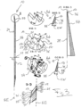
- the Fig. 1 is a plan view of the front of the knife 10, which, during the cutting operation, faces away from the product or products being sliced simultaneously.
- the rotational axis 11 runs centrally through a circular receiving opening 12 of the knife 10, by means of which the knife 10 can be attached to a knife holder of the slicing device (not shown here).
- the knife holder comprises, for example, a rotor hub of a high-speed slicer, as is generally known to those skilled in the art.
- the receiving opening 12 is followed by an end face 38 which, in this embodiment, is planar and runs perpendicular to the axis of rotation 11.
- an inclined surface 37 is connected radially to the outside of the end face 38, from which the individual cutting surfaces 17 of the cutting teeth 15 ( Fig. 2 ) extend radially outwards.
- the tilt angle of the inclined surface 37 i.e. the angle between the inclined surface 37 and a clamping plane AE (cf. Fig. 3 ), is smaller than the smallest tilt angle provided for the cutting surfaces 17.
- the inclined surface 37 is flatter than each cutting surface 17, so that an imaginary radial extension of the inclined surface 37 places the clamping plane AE radially outside the peripheral edge 13 ( Fig. 1 ) would cut.
- Fig. 2 is an enlarged section of Fig. 1 in the immersion area 33, which starts from the top from the smallest radius Rmin of the blade 10, the first nine cutting teeth 15 of the toothing are shown.
- Fig. 2 shows, the cutting surfaces 17 are each delimited radially outwardly by a cutting edge 19. Transitions 27 formed as recesses between the cutting teeth 15 are also delimited radially outwardly by a cutting edge 21 ( Fig. 3 ) which connects two cutting edges 19 of the cutting surfaces 17.
- the transition from the inclined surface 37 into the cutting surfaces 17 of the cutting teeth 15 is formed by a straight inner edge 36, from whose end points an edge extends to the corresponding end point of the respective cutting edge 19.
- These edges 25 ( Fig. 4 ) extend between the inclined surface 37 and the clamping plane AE.
- the inner edges 36 can each be sharp-edged or rounded.
- a transition edge 39 is also formed between the flat end face 38 and the inclined surface 37.
- the edge 39 can be sharp-edged or rounded.
- FIG. 3 The middle upper illustration with the section BB shows an enlarged section of the toothing of the knife 10 of Fig. 1 in the storage area 31.
- the illustration below shows an enlargement of the toothing in the transition area 32
- the illustration below with section CC shows an enlargement of the toothing in the plunge area 33.
- the intended direction of rotation Rot of the knife 10 is indicated in each case by an arrow.
- the cutting surfaces 17 are therefore not only tilted, ie they connect the inner edge 36 located above the clamping plane AE in the inclined surface 37 with the clamping plane AE, but are also angled in the direction of rotation Rot.
- the cutting surfaces 17 of the cutting teeth 15 are both tilted and angled in all three circumferential areas 31, 32 and 33 of the knife toothing.
- the tilt angle KW As for the tilt angle KW, Fig. 3 It can be seen that the tilt angle KW in the storage area 31 (upper middle illustration in Fig. 3 ) is comparatively large.
- the tilt angle KW is preferably 26° here.
- the tilt angle KW In the immersion area 33 (second to last middle illustration in Fig. 3 ) the tilt angle KW is smaller than in storage area 31.
- the tilt angle KW here is preferably 18°.
- the cutting surfaces 17 are therefore flatter or less steep than in the deposit area 31. As already explained at the beginning, this makes it possible in particular to avoid compression of the product when the knife 10 is immersed, whereas at the end of the cutting process, an improved deposit of the respective separated product slice can be achieved due to the steeper cutting surfaces 17 in the deposit area 31.
- the cutting surfaces 17 are tilted such that three consecutive cutting surfaces 17 each have the same tilt angle KW.
- the tilt angle KW decreases by 0.5° from each group of three to the immediately following group of three, with the last group of three before the plunging region 33 having a tilt angle KW of 18.5°, to which the cutting teeth 15 of the plunging region 33 then adjoin, each with a tilt angle KW of the cutting surface 17 of 18°.
- the tilt angle value in the plunging region 33 may again be 18°, whereas in the deposit region 31 the tilt angle value is 22° and each angular step between immediately successive groups of three cutting teeth 15 in the transition region 32 has a value of 0.25°.
- the pitch a of the gearing is constant over the entire circumferential area and is 5 mm in this example.
- the pitch of the gearing can vary, as already explained in the introduction.
- a transition 27 is present between each two immediately successive cutting surfaces 17, which transition is designed as a recess with a U-shaped cross-section running in the radial direction.
- Every transition 27 (see also Fig. 4 ) comprises a transition surface 23 which merges radially inwardly into the inclined surface 37 via a transition edge 35 and is delimited radially outwardly by a transition edge 21 which lies in the cutting plane SE.
- a special feature of this exemplary embodiment according to the invention is that these transition edges 21 connect the cutting edges 19 of the adjacent cutting surfaces 17 and are themselves designed as cutting edges. As a result, all cutting edges 19 and all transition edges 21 connecting two immediately consecutive cutting edges 19 together form a continuous, uninterrupted overall cutting edge.
- this uninterrupted cutting edge formed jointly by the cutting edges 19 and the transition edges 21, lies continuously in the cutting edge plane SE.
- the dash-dotted line runs through the deepest point of the transition surface 23.
- Points 1 and 2 are the intersection points of the dash-dotted line with the cutting plane SE (point 1) and with the inclined surface 37 (point 2), respectively.
- Points 3 and 4 are the intersection points of a first transition edge 25 with the cutting plane SE (point 4) and with the inclined surface 37 (point 3), respectively, whereas points 5 and 6 are the intersection points of a second transition edge 25 with the cutting plane SE (point 5) and the inclined surface 37 (point 6), respectively.
- the two transition edges 25, the cutting edge 19 and the inner edge 36 define the respective cutting surface 17, which in this example is planar, i.e., has no curved profile whatsoever.
- points 1, 4 and 5 as well as the cutting edge 19 connecting points 5 and 4 and the transition edge 21 connecting points 4 and 1 lie in the cutting plane SE, while points 2, 3 and 6 as well as the inner edge 36 connecting points 6 and 3 and the transition edge 35 connecting points 3 and 2 lie in the inclined surface 37.
- points 6 and 3 - measured in the radial direction - are at different distances from the axis of rotation 11, with point 6 being radially further out than point 3 and - since the inclined surface 37 is inclined relative to the cutting plane SE - is therefore closer to the cutting plane SE than point 3, i.e. point 6 is lower than point 3.
- Point 2 in turn, is radially further in than point 3 and consequently higher than point 3 and higher than point 6.
- point 1 is located radially further inward than point 4, which in turn is located radially further inward than point 5.
- all three points 1, 4 and 5 are at the same height level, since they lie in the common cutting plane SE.
- the specific lengths and relative positions of the edges 19, 25, 36 of the relevant cutting surface 17 connecting points 3, 4, 5 and 6 are selected in this embodiment such that the cutting surface 17 is not only tilted but also inclined, specifically such that the cutting surface 17 points in the direction of rotation.
- the cutting surfaces 17 are each positioned such that the cutting surfaces 17 point in the intended direction of rotation red.
- the four corner points 19a, 19b, 36a, and 36b lie in a common plane, namely the plane of the planar cutting surface 17.
- a planar cutting surface 17 is not mandatory.
- the cutting surface 17 can also be concave or curved. It can also be provided that the mentioned corner points do not all lie in a common plane. The cutting surface 17 is then curved accordingly.
- Fig. 4 shows purely as an example the possibilities of clearly defining the orientation of the cutting surface 17 in a knife-fixed reference system.
- FIG. 4 The rear end 19b of the cutting edge 19, viewed in the intended direction of rotation (rot), forms the reference point.
- the movement tangent T' at the rear end 19b is perpendicular to the radius R through the rear end 19b and is identical to the movement vector of the rear end 19b.
- the cutting edge 19 is inclined by an angle ⁇ , such that the cutting edge 19 points in the direction of rotation (rot).
- the lead angle AsW can be defined as the angle between a cutting edge 19 and, for example, the one (in Fig. 4 dash-dotted) connecting section V is defined, which connects the rear end 19b of the respective cutting edge 19 and the rear end 19b of the cutting edge 19 immediately following in the intended direction of rotation Red.
- all of these connecting lines V together form a polygonal line that approximates an imaginary continuous curve, which is not a circle, on which all rear ends 19b of the cutting edges 19 lie and which corresponds at least approximately to the cutting edge of a conventional untoothed sickle blade.
- the front end 19a of each cutting edge does not lie on the respective connecting line V, but rather on a smaller radius, i.e., closer to the axis of rotation of the blade than any point on the connecting line V.
- the cutting edge can also lie on the connecting line V.
- the cutting surfaces 17 can each consist of several individual surfaces, each of which is planar and/or, for example, convexly or concavely curved.
- the cutting surfaces 17 can have angular or rounded transitions between the individual surfaces.
- the cutting surfaces 17 are curved, they are preferably each part of a mathematically regular or differentiable surface and therefore have no edges.
- Fig. 5a shows the definition of the so-called clearance angle FW in a section perpendicular to the cutting plane SE defined by the cutting edge SK and parallel to the rotation axis (not shown).
- FW 0°, i.e., on the rear side of the knife RS, a surface FL adjacent to the cutting edge SK lies in the cutting plane SE.
- the right-hand illustration shows a knife not according to the invention with a clearance angle FW other than zero.
Landscapes
- Life Sciences & Earth Sciences (AREA)
- Forests & Forestry (AREA)
- Engineering & Computer Science (AREA)
- Mechanical Engineering (AREA)
- Food-Manufacturing Devices (AREA)
- Knives (AREA)
- Milling Processes (AREA)
Claims (9)
- Couteau de coupe, en particulier couteau en forme de faucille ou couteau spirale, destiné à un dispositif pour couper des produits alimentaires, en particulier à une trancheuse à haute performance, et étant en rotation autour d'un axe de rotation (11) pendant une opération de coupe, comportantune arête périphérique (13) radialement extérieure faisant office de tranchant, qui présente une allure incurvée autour de l'axe de rotation (11), et une multitude de dents de coupe (15) qui sont agencées en étant réparties successivement le long de l'arête périphérique (13),chaque dent de coupe (15) présentant un tranchant qui comprend une surface de coupe (17) et une arête de coupe (19) délimitant radialement à l'extérieur la surface de coupe (17),dans lequelau moins quelques-unes des arêtes de coupe (19) ou chaque arête de coupe (19) forme(nt) un angle de coupe (AsW), non nul, avec une ligne de liaison (V), la ligne de liaison (V) reliant entre elles les deux extrémités arrière (19b) d'une arête de coupe respective (19) et de l'arête de coupe (19) directement successive, et l'extrémité avant (19a) de l'arête de coupe respective (19) ne se situe pas sur la ligne de liaison (V), mais sur un rayon plus petit,les surfaces de coupe (17) de deux dents de coupe (15) directement successives sont reliées entre elles par une surface de transition respective (23),la surface de transition (23) est réalisée sous la forme d'un renfoncement en retrait par rapport aux surfaces de coupe (17),caractérisé en ce quechaque surface de coupe (17) est reliée aussi bien à la surface de coupe (17) d'une dent de coupe (15) directement précédente qu'à la surface de coupe (17) d'une dent de coupe (15) directement successive, par l'un des renfoncements,la surface de transition (23) est délimitée radialement vers l'extérieur par une arête de transition (21) reliant les deux arêtes de coupe (19) des dents de coupe (15),l'arête de transition (21) est conçue comme une arête de coupe, toutes les arêtes de coupe (19) et toutes les arêtes de transition (21) reliant deux arêtes de coupe (19) respectives directement successives forment conjointement un tranchant non interrompu qui se trouve dans le plan de coupe (SE).
- Couteau selon la revendication 1,
dans lequelle renfoncement est réalisé sous forme d'entaille, de rainure, de sillon ou de gorge s'étendant en direction radiale, et/oule renfoncement constitue un dégagement. - Couteau selon l'une des revendications précédentes,
dans lequelles surfaces de coupe (17) sont chacune positionnées en étant orientées dans la direction de rotation prévue (Rot), et/oules surfaces de coupe (17) sont chacune au moins essentiellement planes ou s'étendent sans arêtes de façon incurvée, en particulier de façon convexe ou concave. - Couteau selon l'une des revendications précédentes,
dans lequell'angle de coupe (AsW) des arêtes de coupe (19) le long de l'arête périphérique (13) est constant et non nul, et/oules arêtes de coupe (19) et/ou les arêtes de transition (21) reliant deux arêtes de coupe respectives (19) directement successives sont chacune rectilignes. - Couteau selon l'une des revendications précédentes,
dans lequel la surface de transition (23) présente en section transversale une allure incurvée en particulier en forme de U ou en forme de V entre les deux surfaces de coupe (17), le côté ouvert du U ou du V étant dirigé dans la même direction que les surfaces de coupe (17). - Couteau selon l'une des revendications précédentes,dans lequel les arêtes de coupe (19) présentent une longueur périphérique constante et/ou une longueur d'arête constante, et/oule pas (a) des dents de coupe (15) est constant et en particulier compris entre environ 3 mm et 6 mm, de préférence est d'environ 5 mm, ou le pas des dents de coupe (15) varie en direction périphérique, en particulier par rapport aux longueurs périphériques des dents de coupe (15) et/ou par rapport aux longueurs périphériques des transitions (27) entre les dents de coupe (15).
- Couteau selon l'une des revendications précédentes,
dans lequell'arête périphérique (13) présente au moins une zone périphérique (31, 33) de type I ayant une pluralité de dents de coupe (15) dont les surfaces de coupe (17) présentent le même angle de basculement (KW), et/oul'arête périphérique (13) présente, en particulier en supplément à au moins une zone périphérique (31, 33) de type I, au moins une zone périphérique (32) de type II ayant une pluralité de dents de coupe (15) dont les surfaces de coupe (17) présentent un angle de basculement variable (KW), etl'angle de basculement (KW) varie respectivement en particulier d'une dent de coupe (15) à une dent de coupe (15) directement voisine, ou l'angle de basculement (KW) varie respectivement d'un groupe de n > 1 dents de coupe successives (15) ayant entre elles le même angle de basculement (KW), à un groupe directement voisin de m > 1 dents de coupe successives (15) ayant entre elles le même angle de basculement (KW), et en particulier, n = m = 2, 3, 4 ou 5. - Couteau selon la revendication 7,
dans lequel
l'arête périphérique (13) entre deux zones périphériques (31, 33) de type I comprend une zone périphérique (32) de type II, dans laquelle la valeur de l'angle de basculement (KW) varie pour passer de la valeur de l'angle de basculement de ladite une zone périphérique (31) de type I à la valeur de l'angle de basculement de l'autre zone périphérique (33) de type I. - Couteau selon la revendication 7 ou 8,dans lequel le rayon de courbure de l'arête périphérique (13), vue en direction de rotation prévue (Rot), diminue pour passer d'un rayon maximal (Rmax) à un rayon minimal (Rmin), etla valeur de l'angle de basculement (KW) de la zone périphérique (32) de type II, vue en direction de rotation (Rot), diminue pour passer d'une valeur d'angle de basculement plus grande à une valeur d'angle de basculement plus petite, en particulier à des pas angulaires de même taille d'une dent de coupe (15) à une autre dent de coupe (15), eten particulier, la valeur d'angle de basculement plus grande de ladite une zone périphérique (31) de type I est dans la plage de 20° à 30° et de préférence entre 22° et 26°, et la valeur d'angle de basculement plus petite de l'autre zone périphérique (33) de type I est dans la plage de 15° à 22° et de préférence entre 17° et 19°, etchaque pas angulaire est dans la plage de 0,2° à 1°, de préférence dans la plage de 0,25° à 0,5°.
Applications Claiming Priority (3)
| Application Number | Priority Date | Filing Date | Title |
|---|---|---|---|
| DE102016124725 | 2016-12-16 | ||
| DE102017108841.5A DE102017108841A1 (de) | 2016-12-16 | 2017-04-25 | Schneidmesser und verfahren zu dessen herstellung |
| EP17205908.1A EP3338972B1 (fr) | 2016-12-16 | 2017-12-07 | Couteau |
Related Parent Applications (2)
| Application Number | Title | Priority Date | Filing Date |
|---|---|---|---|
| EP17205908.1A Division EP3338972B1 (fr) | 2016-12-16 | 2017-12-07 | Couteau |
| EP17205908.1A Division-Into EP3338972B1 (fr) | 2016-12-16 | 2017-12-07 | Couteau |
Publications (3)
| Publication Number | Publication Date |
|---|---|
| EP3459699A1 EP3459699A1 (fr) | 2019-03-27 |
| EP3459699B1 EP3459699B1 (fr) | 2020-09-16 |
| EP3459699B2 true EP3459699B2 (fr) | 2025-06-04 |
Family
ID=60627552
Family Applications (2)
| Application Number | Title | Priority Date | Filing Date |
|---|---|---|---|
| EP18196630.0A Active EP3459699B2 (fr) | 2016-12-16 | 2017-12-07 | Couteau |
| EP17205908.1A Active EP3338972B1 (fr) | 2016-12-16 | 2017-12-07 | Couteau |
Family Applications After (1)
| Application Number | Title | Priority Date | Filing Date |
|---|---|---|---|
| EP17205908.1A Active EP3338972B1 (fr) | 2016-12-16 | 2017-12-07 | Couteau |
Country Status (1)
| Country | Link |
|---|---|
| EP (2) | EP3459699B2 (fr) |
Families Citing this family (3)
| Publication number | Priority date | Publication date | Assignee | Title |
|---|---|---|---|---|
| EP3459699B2 (fr) | 2016-12-16 | 2025-06-04 | Weber Food Technology SE & Co. KG | Couteau |
| DE102019201519A1 (de) | 2019-02-06 | 2020-08-06 | Hagedorn Spiralmesser GmbH | Verzahntes Schneidmesser |
| CN113179750B (zh) * | 2021-05-27 | 2022-03-29 | 新疆农业大学 | 铲切组合式红花采摘机械手及其控制方法 |
Family Cites Families (10)
| Publication number | Priority date | Publication date | Assignee | Title |
|---|---|---|---|---|
| DE3049075A1 (de) * | 1980-12-24 | 1982-07-22 | Johannes Remmert Spezialschleiferei für die Brot-Industrie, 4796 Salzkotten | Maschinenmesser, insbesondere kreis- oder bogenfoermiger gestalt |
| DE3049147C2 (de) * | 1980-12-24 | 1983-09-15 | Johannes Remmert Spezialschleiferei für die Brot-Industrie, 4796 Salzkotten | Maschinenmesser, insbesondere kreis- oder bogenförmiger Gestalt |
| US4660453A (en) | 1985-05-28 | 1987-04-28 | Urschel Laboratories, Inc. | Circular knife and method of making same |
| DE10004836C1 (de) * | 2000-02-01 | 2001-10-31 | Mws Schneidwerkzeuge Gmbh & Co | Rundmesser für Allesschneider und Vorrichtung zur Herstellung der Schneidezahnung |
| US20060021487A1 (en) | 2004-07-30 | 2006-02-02 | William Dickover | Serrated blade for slicing machine |
| DE102007040350A1 (de) | 2007-08-27 | 2009-03-05 | Weber Maschinenbau Gmbh Breidenbach | Schneidmesser |
| FR2988312B1 (fr) | 2012-03-23 | 2014-11-28 | Adiamas | Lame de coupe, procede de realisation d'une telle lame de coupe, installation de mise en oeuvre d'un tel procede |
| CA2898260A1 (fr) * | 2013-01-25 | 2014-07-31 | Gea Food Solutions Germany Gmbh | Lame coupante a angle de coupe variable |
| EP3459699B2 (fr) | 2016-12-16 | 2025-06-04 | Weber Food Technology SE & Co. KG | Couteau |
| DE102017108841A1 (de) | 2016-12-16 | 2018-06-21 | Weber Maschinenbau Gmbh Breidenbach | Schneidmesser und verfahren zu dessen herstellung |
-
2017
- 2017-12-07 EP EP18196630.0A patent/EP3459699B2/fr active Active
- 2017-12-07 EP EP17205908.1A patent/EP3338972B1/fr active Active
Also Published As
| Publication number | Publication date |
|---|---|
| EP3338972A1 (fr) | 2018-06-27 |
| EP3459699A1 (fr) | 2019-03-27 |
| EP3459699B1 (fr) | 2020-09-16 |
| EP3338972B1 (fr) | 2019-07-17 |
Similar Documents
| Publication | Publication Date | Title |
|---|---|---|
| DE102017112177B4 (de) | Schneideinheit sowie Schneidverfahren | |
| EP3069834B1 (fr) | Dispositif de séparation d'un tronçon d'une masse alimentaire pâteuse | |
| DE69601366T2 (de) | Verfahren sowie vorrichtung zum schneiden von teigprodukten | |
| DE102007040350A1 (de) | Schneidmesser | |
| DE102017108841A1 (de) | Schneidmesser und verfahren zu dessen herstellung | |
| DE3878592T2 (de) | Schneidmesseraufbau fuer produkte, die durch druckwasser transportiert werden. | |
| DE102004059479A1 (de) | Rotationsmesser | |
| DE102012109003A1 (de) | Aufschnittschneidemaschine | |
| EP3459699B1 (fr) | Couteau | |
| DE102022113920A1 (de) | Messer, Schneideinheit sowie Aufschneide-Maschine | |
| EP3412417B1 (fr) | Dispositif et procédé de coupe | |
| DE2256467A1 (de) | Schneidvorrichtung mit drehbarem schneidorgan zur herstellung von einschnitten unterschiedlicher laenge in eine sich bewegende werkstoffbahn oder in einen abschnitt einer solchen bahn, und verfahren zur herstellung von briefumschlag-zuschnitten bzw. -rohlingen mit einer bodenklappe | |
| EP2942136A2 (fr) | Dispositif et procédé de découpe en tranches d'un produit alimentaire congelé, en forme de tronçon | |
| EP2522472B1 (fr) | Unité de perforation d'une machine d'emballage | |
| DE102016005443A1 (de) | Schneidmesser, Vorrichtung zum Aufschneiden von Lebensmittelprodukten mit einem solchen Schneidmesser sowie Verwendung und Verfahren zur Herstellung eines Schneidmessers | |
| EP3359356A1 (fr) | Dispositif pour couper un tronçon d'aliments | |
| DE102005058536B4 (de) | Schneidwerkzeugsystem, insbesondere zum Verzahnen von Kegelrädern im Einzel-Teil-Verfahren | |
| EP1582318B1 (fr) | Couteau pour une machine motorisée pour la coupe | |
| WO2021110672A1 (fr) | Appareil de coupe et procédé pour la coupe finale de filets de poisson à partir de poissons qui sont transportés, la queue en avant, dans la direction de transport t le long d'une voie de transport | |
| DE102020103045B4 (de) | Sichelmesser sowie damit ausgestattete Aufschneide-Maschine | |
| EP2014427B1 (fr) | Procédé et dispositif destinés à sectionner des couches de papiers transportées en continu | |
| DE102019111227A1 (de) | Schneidmesser, Hochgeschwindigkeitsslicer und Verfahren zum Aufschneiden von Lebensmittelprodukten | |
| EP0803334B1 (fr) | Couteau rotatif | |
| DE102023122764A1 (de) | Techniken zum Herstellen von Raspeln aus einem Lebensmittelband | |
| DE344942C (de) | Schere zum Zertrennen von T-, I- und anderen Profileisen mit aneinander vorbeigehenden Messern |
Legal Events
| Date | Code | Title | Description |
|---|---|---|---|
| PUAI | Public reference made under article 153(3) epc to a published international application that has entered the european phase |
Free format text: ORIGINAL CODE: 0009012 |
|
| STAA | Information on the status of an ep patent application or granted ep patent |
Free format text: STATUS: THE APPLICATION HAS BEEN PUBLISHED |
|
| AC | Divisional application: reference to earlier application |
Ref document number: 3338972 Country of ref document: EP Kind code of ref document: P |
|
| AK | Designated contracting states |
Kind code of ref document: A1 Designated state(s): AL AT BE BG CH CY CZ DE DK EE ES FI FR GB GR HR HU IE IS IT LI LT LU LV MC MK MT NL NO PL PT RO RS SE SI SK SM TR |
|
| AX | Request for extension of the european patent |
Extension state: BA ME |
|
| STAA | Information on the status of an ep patent application or granted ep patent |
Free format text: STATUS: REQUEST FOR EXAMINATION WAS MADE |
|
| 17P | Request for examination filed |
Effective date: 20190926 |
|
| RBV | Designated contracting states (corrected) |
Designated state(s): AL AT BE BG CH CY CZ DE DK EE ES FI FR GB GR HR HU IE IS IT LI LT LU LV MC MK MT NL NO PL PT RO RS SE SI SK SM TR |
|
| GRAP | Despatch of communication of intention to grant a patent |
Free format text: ORIGINAL CODE: EPIDOSNIGR1 |
|
| STAA | Information on the status of an ep patent application or granted ep patent |
Free format text: STATUS: GRANT OF PATENT IS INTENDED |
|
| INTG | Intention to grant announced |
Effective date: 20200514 |
|
| GRAS | Grant fee paid |
Free format text: ORIGINAL CODE: EPIDOSNIGR3 |
|
| GRAA | (expected) grant |
Free format text: ORIGINAL CODE: 0009210 |
|
| STAA | Information on the status of an ep patent application or granted ep patent |
Free format text: STATUS: THE PATENT HAS BEEN GRANTED |
|
| AC | Divisional application: reference to earlier application |
Ref document number: 3338972 Country of ref document: EP Kind code of ref document: P |
|
| AK | Designated contracting states |
Kind code of ref document: B1 Designated state(s): AL AT BE BG CH CY CZ DE DK EE ES FI FR GB GR HR HU IE IS IT LI LT LU LV MC MK MT NL NO PL PT RO RS SE SI SK SM TR |
|
| REG | Reference to a national code |
Ref country code: GB Ref legal event code: FG4D Free format text: NOT ENGLISH |
|
| REG | Reference to a national code |
Ref country code: CH Ref legal event code: EP |
|
| REG | Reference to a national code |
Ref country code: DE Ref legal event code: R096 Ref document number: 502017007352 Country of ref document: DE |
|
| REG | Reference to a national code |
Ref country code: IE Ref legal event code: FG4D Free format text: LANGUAGE OF EP DOCUMENT: GERMAN |
|
| REG | Reference to a national code |
Ref country code: AT Ref legal event code: REF Ref document number: 1313730 Country of ref document: AT Kind code of ref document: T Effective date: 20201015 |
|
| PG25 | Lapsed in a contracting state [announced via postgrant information from national office to epo] |
Ref country code: FI Free format text: LAPSE BECAUSE OF FAILURE TO SUBMIT A TRANSLATION OF THE DESCRIPTION OR TO PAY THE FEE WITHIN THE PRESCRIBED TIME-LIMIT Effective date: 20200916 Ref country code: NO Free format text: LAPSE BECAUSE OF FAILURE TO SUBMIT A TRANSLATION OF THE DESCRIPTION OR TO PAY THE FEE WITHIN THE PRESCRIBED TIME-LIMIT Effective date: 20201216 Ref country code: HR Free format text: LAPSE BECAUSE OF FAILURE TO SUBMIT A TRANSLATION OF THE DESCRIPTION OR TO PAY THE FEE WITHIN THE PRESCRIBED TIME-LIMIT Effective date: 20200916 Ref country code: GR Free format text: LAPSE BECAUSE OF FAILURE TO SUBMIT A TRANSLATION OF THE DESCRIPTION OR TO PAY THE FEE WITHIN THE PRESCRIBED TIME-LIMIT Effective date: 20201217 Ref country code: SE Free format text: LAPSE BECAUSE OF FAILURE TO SUBMIT A TRANSLATION OF THE DESCRIPTION OR TO PAY THE FEE WITHIN THE PRESCRIBED TIME-LIMIT Effective date: 20200916 Ref country code: BG Free format text: LAPSE BECAUSE OF FAILURE TO SUBMIT A TRANSLATION OF THE DESCRIPTION OR TO PAY THE FEE WITHIN THE PRESCRIBED TIME-LIMIT Effective date: 20201216 |
|
| REG | Reference to a national code |
Ref country code: NL Ref legal event code: MP Effective date: 20200916 |
|
| PG25 | Lapsed in a contracting state [announced via postgrant information from national office to epo] |
Ref country code: LV Free format text: LAPSE BECAUSE OF FAILURE TO SUBMIT A TRANSLATION OF THE DESCRIPTION OR TO PAY THE FEE WITHIN THE PRESCRIBED TIME-LIMIT Effective date: 20200916 Ref country code: RS Free format text: LAPSE BECAUSE OF FAILURE TO SUBMIT A TRANSLATION OF THE DESCRIPTION OR TO PAY THE FEE WITHIN THE PRESCRIBED TIME-LIMIT Effective date: 20200916 |
|
| REG | Reference to a national code |
Ref country code: LT Ref legal event code: MG4D |
|
| PG25 | Lapsed in a contracting state [announced via postgrant information from national office to epo] |
Ref country code: SM Free format text: LAPSE BECAUSE OF FAILURE TO SUBMIT A TRANSLATION OF THE DESCRIPTION OR TO PAY THE FEE WITHIN THE PRESCRIBED TIME-LIMIT Effective date: 20200916 Ref country code: LT Free format text: LAPSE BECAUSE OF FAILURE TO SUBMIT A TRANSLATION OF THE DESCRIPTION OR TO PAY THE FEE WITHIN THE PRESCRIBED TIME-LIMIT Effective date: 20200916 Ref country code: EE Free format text: LAPSE BECAUSE OF FAILURE TO SUBMIT A TRANSLATION OF THE DESCRIPTION OR TO PAY THE FEE WITHIN THE PRESCRIBED TIME-LIMIT Effective date: 20200916 Ref country code: RO Free format text: LAPSE BECAUSE OF FAILURE TO SUBMIT A TRANSLATION OF THE DESCRIPTION OR TO PAY THE FEE WITHIN THE PRESCRIBED TIME-LIMIT Effective date: 20200916 Ref country code: PT Free format text: LAPSE BECAUSE OF FAILURE TO SUBMIT A TRANSLATION OF THE DESCRIPTION OR TO PAY THE FEE WITHIN THE PRESCRIBED TIME-LIMIT Effective date: 20210118 Ref country code: CZ Free format text: LAPSE BECAUSE OF FAILURE TO SUBMIT A TRANSLATION OF THE DESCRIPTION OR TO PAY THE FEE WITHIN THE PRESCRIBED TIME-LIMIT Effective date: 20200916 |
|
| PG25 | Lapsed in a contracting state [announced via postgrant information from national office to epo] |
Ref country code: PL Free format text: LAPSE BECAUSE OF FAILURE TO SUBMIT A TRANSLATION OF THE DESCRIPTION OR TO PAY THE FEE WITHIN THE PRESCRIBED TIME-LIMIT Effective date: 20200916 Ref country code: IS Free format text: LAPSE BECAUSE OF FAILURE TO SUBMIT A TRANSLATION OF THE DESCRIPTION OR TO PAY THE FEE WITHIN THE PRESCRIBED TIME-LIMIT Effective date: 20210116 Ref country code: ES Free format text: LAPSE BECAUSE OF FAILURE TO SUBMIT A TRANSLATION OF THE DESCRIPTION OR TO PAY THE FEE WITHIN THE PRESCRIBED TIME-LIMIT Effective date: 20200916 Ref country code: AL Free format text: LAPSE BECAUSE OF FAILURE TO SUBMIT A TRANSLATION OF THE DESCRIPTION OR TO PAY THE FEE WITHIN THE PRESCRIBED TIME-LIMIT Effective date: 20200916 |
|
| REG | Reference to a national code |
Ref country code: DE Ref legal event code: R026 Ref document number: 502017007352 Country of ref document: DE |
|
| PLBI | Opposition filed |
Free format text: ORIGINAL CODE: 0009260 |
|
| PLBI | Opposition filed |
Free format text: ORIGINAL CODE: 0009260 |
|
| PLAX | Notice of opposition and request to file observation + time limit sent |
Free format text: ORIGINAL CODE: EPIDOSNOBS2 |
|
| PG25 | Lapsed in a contracting state [announced via postgrant information from national office to epo] |
Ref country code: SK Free format text: LAPSE BECAUSE OF FAILURE TO SUBMIT A TRANSLATION OF THE DESCRIPTION OR TO PAY THE FEE WITHIN THE PRESCRIBED TIME-LIMIT Effective date: 20200916 |
|
| 26 | Opposition filed |
Opponent name: GEA FOOD SOLUTIONS GERMANY GMBH Effective date: 20210614 |
|
| 26 | Opposition filed |
Opponent name: HAGEDORN SPIRALMESSER GMBH Effective date: 20210616 |
|
| REG | Reference to a national code |
Ref country code: CH Ref legal event code: PL |
|
| PG25 | Lapsed in a contracting state [announced via postgrant information from national office to epo] |
Ref country code: DK Free format text: LAPSE BECAUSE OF FAILURE TO SUBMIT A TRANSLATION OF THE DESCRIPTION OR TO PAY THE FEE WITHIN THE PRESCRIBED TIME-LIMIT Effective date: 20200916 Ref country code: SI Free format text: LAPSE BECAUSE OF FAILURE TO SUBMIT A TRANSLATION OF THE DESCRIPTION OR TO PAY THE FEE WITHIN THE PRESCRIBED TIME-LIMIT Effective date: 20200916 Ref country code: MC Free format text: LAPSE BECAUSE OF FAILURE TO SUBMIT A TRANSLATION OF THE DESCRIPTION OR TO PAY THE FEE WITHIN THE PRESCRIBED TIME-LIMIT Effective date: 20200916 |
|
| REG | Reference to a national code |
Ref country code: BE Ref legal event code: MM Effective date: 20201231 |
|
| PG25 | Lapsed in a contracting state [announced via postgrant information from national office to epo] |
Ref country code: FR Free format text: LAPSE BECAUSE OF NON-PAYMENT OF DUE FEES Effective date: 20201231 Ref country code: IE Free format text: LAPSE BECAUSE OF NON-PAYMENT OF DUE FEES Effective date: 20201207 Ref country code: LU Free format text: LAPSE BECAUSE OF NON-PAYMENT OF DUE FEES Effective date: 20201207 |
|
| PLBB | Reply of patent proprietor to notice(s) of opposition received |
Free format text: ORIGINAL CODE: EPIDOSNOBS3 |
|
| PG25 | Lapsed in a contracting state [announced via postgrant information from national office to epo] |
Ref country code: CH Free format text: LAPSE BECAUSE OF NON-PAYMENT OF DUE FEES Effective date: 20201231 Ref country code: LI Free format text: LAPSE BECAUSE OF NON-PAYMENT OF DUE FEES Effective date: 20201231 |
|
| PG25 | Lapsed in a contracting state [announced via postgrant information from national office to epo] |
Ref country code: TR Free format text: LAPSE BECAUSE OF FAILURE TO SUBMIT A TRANSLATION OF THE DESCRIPTION OR TO PAY THE FEE WITHIN THE PRESCRIBED TIME-LIMIT Effective date: 20200916 Ref country code: MT Free format text: LAPSE BECAUSE OF FAILURE TO SUBMIT A TRANSLATION OF THE DESCRIPTION OR TO PAY THE FEE WITHIN THE PRESCRIBED TIME-LIMIT Effective date: 20200916 Ref country code: CY Free format text: LAPSE BECAUSE OF FAILURE TO SUBMIT A TRANSLATION OF THE DESCRIPTION OR TO PAY THE FEE WITHIN THE PRESCRIBED TIME-LIMIT Effective date: 20200916 |
|
| PG25 | Lapsed in a contracting state [announced via postgrant information from national office to epo] |
Ref country code: MK Free format text: LAPSE BECAUSE OF FAILURE TO SUBMIT A TRANSLATION OF THE DESCRIPTION OR TO PAY THE FEE WITHIN THE PRESCRIBED TIME-LIMIT Effective date: 20200916 |
|
| PG25 | Lapsed in a contracting state [announced via postgrant information from national office to epo] |
Ref country code: BE Free format text: LAPSE BECAUSE OF NON-PAYMENT OF DUE FEES Effective date: 20201231 |
|
| APAH | Appeal reference modified |
Free format text: ORIGINAL CODE: EPIDOSCREFNO |
|
| APAW | Appeal reference deleted |
Free format text: ORIGINAL CODE: EPIDOSDREFNO |
|
| APAY | Date of receipt of notice of appeal deleted |
Free format text: ORIGINAL CODE: EPIDOSDNOA2O |
|
| APBM | Appeal reference recorded |
Free format text: ORIGINAL CODE: EPIDOSNREFNO |
|
| APBP | Date of receipt of notice of appeal recorded |
Free format text: ORIGINAL CODE: EPIDOSNNOA2O |
|
| APBQ | Date of receipt of statement of grounds of appeal recorded |
Free format text: ORIGINAL CODE: EPIDOSNNOA3O |
|
| APBQ | Date of receipt of statement of grounds of appeal recorded |
Free format text: ORIGINAL CODE: EPIDOSNNOA3O |
|
| P01 | Opt-out of the competence of the unified patent court (upc) registered |
Effective date: 20230522 |
|
| PG25 | Lapsed in a contracting state [announced via postgrant information from national office to epo] |
Ref country code: NL Free format text: LAPSE BECAUSE OF NON-PAYMENT OF DUE FEES Effective date: 20200923 |
|
| REG | Reference to a national code |
Ref country code: AT Ref legal event code: MM01 Ref document number: 1313730 Country of ref document: AT Kind code of ref document: T Effective date: 20221207 |
|
| RAP4 | Party data changed (patent owner data changed or rights of a patent transferred) |
Owner name: WEBER FOOD TECHNOLOGY GMBH |
|
| REG | Reference to a national code |
Ref country code: DE Ref legal event code: R081 Ref document number: 502017007352 Country of ref document: DE Owner name: WEBER FOOD TECHNOLOGY SE & CO. KG, DE Free format text: FORMER OWNER: WEBER MASCHINENBAU GMBH BREIDENBACH, 35236 BREIDENBACH, DE Ref country code: DE Ref legal event code: R081 Ref document number: 502017007352 Country of ref document: DE Owner name: WEBER FOOD TECHNOLOGY GMBH, DE Free format text: FORMER OWNER: WEBER MASCHINENBAU GMBH BREIDENBACH, 35236 BREIDENBACH, DE |
|
| PG25 | Lapsed in a contracting state [announced via postgrant information from national office to epo] |
Ref country code: AT Free format text: LAPSE BECAUSE OF NON-PAYMENT OF DUE FEES Effective date: 20221207 |
|
| PG25 | Lapsed in a contracting state [announced via postgrant information from national office to epo] |
Ref country code: AT Free format text: LAPSE BECAUSE OF NON-PAYMENT OF DUE FEES Effective date: 20221207 |
|
| APBU | Appeal procedure closed |
Free format text: ORIGINAL CODE: EPIDOSNNOA9O |
|
| REG | Reference to a national code |
Ref country code: DE Ref legal event code: R081 Ref document number: 502017007352 Country of ref document: DE Owner name: WEBER FOOD TECHNOLOGY SE & CO. KG, DE Free format text: FORMER OWNER: WEBER FOOD TECHNOLOGY GMBH, 35236 BREIDENBACH, DE |
|
| REG | Reference to a national code |
Ref country code: GB Ref legal event code: 732E Free format text: REGISTERED BETWEEN 20250206 AND 20250212 |
|
| RAP2 | Party data changed (patent owner data changed or rights of a patent transferred) |
Owner name: WEBER FOOD TECHNOLOGY SE & CO. KG |
|
| PUAH | Patent maintained in amended form |
Free format text: ORIGINAL CODE: 0009272 |
|
| STAA | Information on the status of an ep patent application or granted ep patent |
Free format text: STATUS: PATENT MAINTAINED AS AMENDED |
|
| 27A | Patent maintained in amended form |
Effective date: 20250604 |
|
| AK | Designated contracting states |
Kind code of ref document: B2 Designated state(s): AL AT BE BG CH CY CZ DE DK EE ES FI FR GB GR HR HU IE IS IT LI LT LU LV MC MK MT NL NO PL PT RO RS SE SI SK SM TR |
|
| REG | Reference to a national code |
Ref country code: DE Ref legal event code: R102 Ref document number: 502017007352 Country of ref document: DE |
|
| PGFP | Annual fee paid to national office [announced via postgrant information from national office to epo] |
Ref country code: GB Payment date: 20251218 Year of fee payment: 9 |
|
| PGFP | Annual fee paid to national office [announced via postgrant information from national office to epo] |
Ref country code: DE Payment date: 20251222 Year of fee payment: 9 |
|
| PGFP | Annual fee paid to national office [announced via postgrant information from national office to epo] |
Ref country code: AT Payment date: 20260410 Year of fee payment: 5 |
|
| PGFP | Annual fee paid to national office [announced via postgrant information from national office to epo] |
Ref country code: IT Payment date: 20251231 Year of fee payment: 9 |