EP3459781A2 - Système de transport ferroviaire, système ferroviaire et véhicule ferroviaire pour un système de transport ferroviaire - Google Patents
Système de transport ferroviaire, système ferroviaire et véhicule ferroviaire pour un système de transport ferroviaire Download PDFInfo
- Publication number
- EP3459781A2 EP3459781A2 EP18191988.7A EP18191988A EP3459781A2 EP 3459781 A2 EP3459781 A2 EP 3459781A2 EP 18191988 A EP18191988 A EP 18191988A EP 3459781 A2 EP3459781 A2 EP 3459781A2
- Authority
- EP
- European Patent Office
- Prior art keywords
- rail
- rail vehicle
- chassis
- vehicle
- transport system
- Prior art date
- Legal status (The legal status is an assumption and is not a legal conclusion. Google has not performed a legal analysis and makes no representation as to the accuracy of the status listed.)
- Withdrawn
Links
Images

Classifications
-
- B—PERFORMING OPERATIONS; TRANSPORTING
- B60—VEHICLES IN GENERAL
- B60L—PROPULSION OF ELECTRICALLY-PROPELLED VEHICLES; SUPPLYING ELECTRIC POWER FOR AUXILIARY EQUIPMENT OF ELECTRICALLY-PROPELLED VEHICLES; ELECTRODYNAMIC BRAKE SYSTEMS FOR VEHICLES IN GENERAL; MAGNETIC SUSPENSION OR LEVITATION FOR VEHICLES; MONITORING OPERATING VARIABLES OF ELECTRICALLY-PROPELLED VEHICLES; ELECTRIC SAFETY DEVICES FOR ELECTRICALLY-PROPELLED VEHICLES
- B60L5/00—Current collectors for power supply lines of electrically-propelled vehicles
- B60L5/005—Current collectors for power supply lines of electrically-propelled vehicles without mechanical contact between the collector and the power supply line
-
- H—ELECTRICITY
- H04—ELECTRIC COMMUNICATION TECHNIQUE
- H04B—TRANSMISSION
- H04B5/00—Near-field transmission systems, e.g. inductive or capacitive transmission systems
- H04B5/20—Near-field transmission systems, e.g. inductive or capacitive transmission systems characterised by the transmission technique; characterised by the transmission medium
- H04B5/24—Inductive coupling
- H04B5/26—Inductive coupling using coils
-
- B—PERFORMING OPERATIONS; TRANSPORTING
- B60—VEHICLES IN GENERAL
- B60L—PROPULSION OF ELECTRICALLY-PROPELLED VEHICLES; SUPPLYING ELECTRIC POWER FOR AUXILIARY EQUIPMENT OF ELECTRICALLY-PROPELLED VEHICLES; ELECTRODYNAMIC BRAKE SYSTEMS FOR VEHICLES IN GENERAL; MAGNETIC SUSPENSION OR LEVITATION FOR VEHICLES; MONITORING OPERATING VARIABLES OF ELECTRICALLY-PROPELLED VEHICLES; ELECTRIC SAFETY DEVICES FOR ELECTRICALLY-PROPELLED VEHICLES
- B60L5/00—Current collectors for power supply lines of electrically-propelled vehicles
- B60L5/38—Current collectors for power supply lines of electrically-propelled vehicles for collecting current from conductor rails
- B60L5/39—Current collectors for power supply lines of electrically-propelled vehicles for collecting current from conductor rails from third rail
-
- B—PERFORMING OPERATIONS; TRANSPORTING
- B60—VEHICLES IN GENERAL
- B60L—PROPULSION OF ELECTRICALLY-PROPELLED VEHICLES; SUPPLYING ELECTRIC POWER FOR AUXILIARY EQUIPMENT OF ELECTRICALLY-PROPELLED VEHICLES; ELECTRODYNAMIC BRAKE SYSTEMS FOR VEHICLES IN GENERAL; MAGNETIC SUSPENSION OR LEVITATION FOR VEHICLES; MONITORING OPERATING VARIABLES OF ELECTRICALLY-PROPELLED VEHICLES; ELECTRIC SAFETY DEVICES FOR ELECTRICALLY-PROPELLED VEHICLES
- B60L9/00—Electric propulsion with power supply external to the vehicle
-
- B—PERFORMING OPERATIONS; TRANSPORTING
- B60—VEHICLES IN GENERAL
- B60M—POWER SUPPLY LINES, AND DEVICES ALONG RAILS, FOR ELECTRICALLY- PROPELLED VEHICLES
- B60M1/00—Power supply lines for contact with collector on vehicle
- B60M1/30—Power rails
- B60M1/32—Crossings; Points
-
- B—PERFORMING OPERATIONS; TRANSPORTING
- B61—RAILWAYS
- B61B—RAILWAY SYSTEMS; EQUIPMENT THEREFOR NOT OTHERWISE PROVIDED FOR
- B61B5/00—Elevated railway systems without suspended vehicles
- B61B5/02—Elevated railway systems without suspended vehicles with two or more rails
-
- B—PERFORMING OPERATIONS; TRANSPORTING
- B66—HOISTING; LIFTING; HAULING
- B66B—ELEVATORS; ESCALATORS OR MOVING WALKWAYS
- B66B7/00—Other common features of elevators
-
- B—PERFORMING OPERATIONS; TRANSPORTING
- B66—HOISTING; LIFTING; HAULING
- B66C—CRANES; LOAD-ENGAGING ELEMENTS OR DEVICES FOR CRANES, CAPSTANS, WINCHES, OR TACKLES
- B66C7/00—Runways, tracks or trackways for trolleys or cranes
- B66C7/12—Devices for changing direction of travel or for transferring from one runway to another; Crossings; Combinations of tracks of different gauges
-
- H—ELECTRICITY
- H02—GENERATION; CONVERSION OR DISTRIBUTION OF ELECTRIC POWER
- H02J—ELECTRIC POWER NETWORKS; CIRCUIT ARRANGEMENTS OR SYSTEMS FOR SUPPLYING OR DISTRIBUTING ELECTRIC POWER; SYSTEMS FOR STORING ELECTRIC ENERGY
- H02J50/00—Circuit arrangements or systems for wireless supply or distribution of electric power
- H02J50/10—Circuit arrangements or systems for wireless supply or distribution of electric power using inductive coupling
-
- B—PERFORMING OPERATIONS; TRANSPORTING
- B60—VEHICLES IN GENERAL
- B60L—PROPULSION OF ELECTRICALLY-PROPELLED VEHICLES; SUPPLYING ELECTRIC POWER FOR AUXILIARY EQUIPMENT OF ELECTRICALLY-PROPELLED VEHICLES; ELECTRODYNAMIC BRAKE SYSTEMS FOR VEHICLES IN GENERAL; MAGNETIC SUSPENSION OR LEVITATION FOR VEHICLES; MONITORING OPERATING VARIABLES OF ELECTRICALLY-PROPELLED VEHICLES; ELECTRIC SAFETY DEVICES FOR ELECTRICALLY-PROPELLED VEHICLES
- B60L2200/00—Type of vehicles
- B60L2200/26—Rail vehicles
-
- B—PERFORMING OPERATIONS; TRANSPORTING
- B60—VEHICLES IN GENERAL
- B60L—PROPULSION OF ELECTRICALLY-PROPELLED VEHICLES; SUPPLYING ELECTRIC POWER FOR AUXILIARY EQUIPMENT OF ELECTRICALLY-PROPELLED VEHICLES; ELECTRODYNAMIC BRAKE SYSTEMS FOR VEHICLES IN GENERAL; MAGNETIC SUSPENSION OR LEVITATION FOR VEHICLES; MONITORING OPERATING VARIABLES OF ELECTRICALLY-PROPELLED VEHICLES; ELECTRIC SAFETY DEVICES FOR ELECTRICALLY-PROPELLED VEHICLES
- B60L2200/00—Type of vehicles
- B60L2200/40—Working vehicles
- B60L2200/44—Industrial trucks or floor conveyors
-
- B—PERFORMING OPERATIONS; TRANSPORTING
- B65—CONVEYING; PACKING; STORING; HANDLING THIN OR FILAMENTARY MATERIAL
- B65G—TRANSPORT OR STORAGE DEVICES, e.g. CONVEYORS FOR LOADING OR TIPPING, SHOP CONVEYOR SYSTEMS OR PNEUMATIC TUBE CONVEYORS
- B65G47/00—Article or material-handling devices associated with conveyors; Methods employing such devices
- B65G47/74—Feeding, transfer, or discharging devices of particular kinds or types
- B65G47/80—Turntables carrying articles or materials to be transferred, e.g. combined with ploughs or scrapers
-
- B—PERFORMING OPERATIONS; TRANSPORTING
- B65—CONVEYING; PACKING; STORING; HANDLING THIN OR FILAMENTARY MATERIAL
- B65G—TRANSPORT OR STORAGE DEVICES, e.g. CONVEYORS FOR LOADING OR TIPPING, SHOP CONVEYOR SYSTEMS OR PNEUMATIC TUBE CONVEYORS
- B65G54/00—Non-mechanical conveyors not otherwise provided for
- B65G54/02—Non-mechanical conveyors not otherwise provided for electrostatic, electric, or magnetic
-
- H—ELECTRICITY
- H04—ELECTRIC COMMUNICATION TECHNIQUE
- H04B—TRANSMISSION
- H04B5/00—Near-field transmission systems, e.g. inductive or capacitive transmission systems
- H04B5/20—Near-field transmission systems, e.g. inductive or capacitive transmission systems characterised by the transmission technique; characterised by the transmission medium
- H04B5/24—Inductive coupling
-
- H—ELECTRICITY
- H04—ELECTRIC COMMUNICATION TECHNIQUE
- H04B—TRANSMISSION
- H04B5/00—Near-field transmission systems, e.g. inductive or capacitive transmission systems
- H04B5/70—Near-field transmission systems, e.g. inductive or capacitive transmission systems specially adapted for specific purposes
- H04B5/79—Near-field transmission systems, e.g. inductive or capacitive transmission systems specially adapted for specific purposes for data transfer in combination with power transfer
-
- Y—GENERAL TAGGING OF NEW TECHNOLOGICAL DEVELOPMENTS; GENERAL TAGGING OF CROSS-SECTIONAL TECHNOLOGIES SPANNING OVER SEVERAL SECTIONS OF THE IPC; TECHNICAL SUBJECTS COVERED BY FORMER USPC CROSS-REFERENCE ART COLLECTIONS [XRACs] AND DIGESTS
- Y02—TECHNOLOGIES OR APPLICATIONS FOR MITIGATION OR ADAPTATION AGAINST CLIMATE CHANGE
- Y02P—CLIMATE CHANGE MITIGATION TECHNOLOGIES IN THE PRODUCTION OR PROCESSING OF GOODS
- Y02P90/00—Enabling technologies with a potential contribution to greenhouse gas [GHG] emissions mitigation
- Y02P90/60—Electric or hybrid propulsion means for production processes
-
- Y—GENERAL TAGGING OF NEW TECHNOLOGICAL DEVELOPMENTS; GENERAL TAGGING OF CROSS-SECTIONAL TECHNOLOGIES SPANNING OVER SEVERAL SECTIONS OF THE IPC; TECHNICAL SUBJECTS COVERED BY FORMER USPC CROSS-REFERENCE ART COLLECTIONS [XRACs] AND DIGESTS
- Y02—TECHNOLOGIES OR APPLICATIONS FOR MITIGATION OR ADAPTATION AGAINST CLIMATE CHANGE
- Y02T—CLIMATE CHANGE MITIGATION TECHNOLOGIES RELATED TO TRANSPORTATION
- Y02T10/00—Road transport of goods or passengers
- Y02T10/60—Other road transportation technologies with climate change mitigation effect
- Y02T10/70—Energy storage systems for electromobility, e.g. batteries
Definitions
- the invention relates to a rail-bound transport system according to the preamble of claim 1. Furthermore, the invention relates to a rail system according to the preamble of claim 11. Finally, the invention relates to a rail vehicle according to the preamble of claim 13.
- the rail-bound transport systems described here are designed for transporting payloads in in-house logistics. For example, goods and / or goods, but also containers and / or devices can be transported. In principle, the dimensions and further properties of both the transport system as a whole as well as the individual components are adapted to this in-house traffic and the associated requirements.
- the so-called in-house logistics relates in particular to transport processes, such as those typically occurring within production facilities, production facilities, warehouses or picking units, for example.
- rail systems on which rail vehicles can travel.
- the rail vehicles on suitable rolling elements, so for example wheels. With this they can be moved along the rails relatively low friction.
- a rail-bound transport system with the features of claim 1.
- Such a rail-bound transport system is provided for the internal logistics for the transport of transport units, in particular containers and / or goods and / or goods and / or equipment. It has a rail system, in particular a rail network, wherein at least one rail vehicle is movably arranged along the rail system.
- the at least one rail vehicle has at least one chassis, in particular with a plurality of rolling elements and / or wheels.
- at least one own, preferably electric drive is provided.
- the rail vehicle can be moved along the rail system or the rail travel, preferably method.
- the rail-bound transport system is characterized in that along the rail system or rail network means for inductive energy transfer of electrical energy to the at least one rail vehicle are provided.
- the at least one rail vehicle along the rail network can be supplied with electrical energy by means of inductive energy transmission.
- inductive energy transmission For a contactless energy transfer is possible, so that in particular friction and wear can be avoided.
- An inductive supply can be achieved in the usual way by means of electromagnetic alternating fields.
- the inductive energy transfer along the entire rail network is provided. Further preferably, this is at least substantially uninterrupted, that is without substantial or even without interruptions. This is especially important at transitions of different sections of track and / or also on points.
- means for inductive energy transmission are assigned to the rail system or rail network, in particular the entire rail system.
- means for inductive energy transfer are assigned on the one hand to the rail network and on the other hand to the rail vehicle.
- a continuous supply makes it possible to dispense with means for bridging, such as electricity storage or the like.
- means for bridging interruptions power storage, such as batteries, capacitors or the like should be provided.
- the rail-bound transport system preferably has at least one electrical energy transmission means. It is further preferably at least one electrical conductor for inductive energy transmission provided, which serves in particular as an electrical energy transmission means. This may in particular also be at least one coil, preferably a plurality of coils. Thus, an inductive energy transfer can be ensured.
- the at least one electrical energy transmission means is preferably arranged on the one hand preferably on and / or in the region of the rail system or of the rail network and / or on the other hand of the rail vehicle.
- these are corresponding energy transmission means on the rail system and on the rail vehicle.
- At least one inductive busbar is particularly preferably provided on the rail system side. This is preferably formed as a long-drawn and / or flat element.
- the busbar includes corresponding inductively operating components, such as electrical conductors or coils.
- On the rail vehicle side at least one inductive current collector engaging with the busbar is preferably formed.
- the current collector is preferably formed the busbar at least partially encompassing, more preferably U-shaped. Accordingly, the current collector preferably surrounds the busbar, in particular from one side, so that the legs of the current collector are preferably arranged above and below the busbar. In this case, a non-contact arrangement is preferably provided, in particular by corresponding distances between pantograph and busbar.
- the current collector also has corresponding inductively operating components, such as electrical conductors or coils.
- the inductive components of busbar and current collector correspond with each other, in particular with regard to the electromagnetic alternating fields to be generated for the inductive energy transfer.
- a safe and smooth energy transfer can be ensured.
- a plurality of busbars in particular on both sides of the rail system and / or one above the other, and / or a plurality of current collectors, in particular on both sides of the rail system and / or one above the other and / or in succession, may be provided. This makes it possible to ensure even better interruption of the power supply.
- the at least one rail vehicle has in particular at least one chassis.
- the at least one transport unit is preferably fastened to the chassis, in particular detachable.
- the at least one transport unit of the chassis of the at least one rail vehicle is designed as a means for transporting a payload, preferably as a container and / or as a device receptacle. This can be used for different purposes. In addition to the transport of goods and goods in containers and special work assignments could be provided, in particular by suitable equipment.
- the at least one rail vehicle has separate electric drives for each of the wheels.
- the electric drives are preferably independently controllable.
- the wheels and / or the drives are arranged in particular chassis and / or on the chassis or attached thereto.
- the chassis is preferably connected to the chassis.
- an operation of the chassis of the rail vehicle can be achieved regardless of the payload.
- At least one compressed air supply is provided for the at least one rail vehicle.
- the compressed air supply is preferably arranged in the region of the rail system, more preferably on the rail system. It is preferably provided for this purpose at least one connection piece for connection to an external compressed air supply.
- at least one compressed air unit in particular an electric compressed air unit, be provided on the rail vehicle, in particular at least as part of the payload.
- the compressed air can be removed, in particular at corresponding stations, from a stationary source, for example via corresponding compressed air lines or compressed air connections. A connection can then be made specifically at these removal points, in particular automatically, for example by accurately starting a connection with a corresponding counterpart.
- a mobile compressed air supply on the rail vehicle can be done by carrying a compressor. This can then be operated electrically.
- an elevator system is provided as part of the rail system. It further preferably has a movable replacement rail section for closing an open connection between two rail sections during operation of the elevator system by moving away a rail section.
- the replacement rail section is preferably provided with a lifting device, in particular a scissor lift, so as to introduce the replacement rail section into a gap between two rail sections. Such a gap arises in particular when the elevator system moves the elevator car to another level.
- At least one data connection is provided between the rail system and the at least one rail vehicle.
- the data connection is further preferably provided inductively, that is analogous to the power supply.
- the data transmission via the energy transmission means for electrical power supply, so to speak in addition for energy supply. To use the existing transmission links only a corresponding coding of the data must be made.
- the rail system has in particular, apart from simple linear or curvy sections, additional components for controlling the movement of the rail vehicles along the rail system.
- Such control devices are used to build a complex rail system that can meet high demands.
- the power supply also takes place in the area of these transitions without interruption or at least almost without interruption.
- means for bridging the power supply such as batteries, rechargeable batteries or the like.
- the object described above is also achieved by a rail system, in particular a rail network, with the features of claim 11.
- the rail system is provided for a rail-bound transport system, as described in particular above. It has rail sections for locomotion of at least one rail vehicle along it.
- at least one chassis preferably by means of the rail vehicle associated rolling elements, preferably wheels.
- the at least one rail vehicle also has at least one separate, in particular electric drive.
- the rail network is characterized in that inductive power supply means are provided for ensuring the supply of the at least one rail vehicle with electrical energy. This ensures a contactless and safe energy transfer, especially without interruptions.
- An inductive power supply can be achieved in the usual way by means of electromagnetic alternating fields.
- locomotion components are provided, which are provided for influencing and / or controlling the movement of the at least one rail vehicle along the rail system.
- the locomotion components are elevators, turntables, branches and points.
- the locomotion components are preferably arranged subsequently and / or between straight and / or curved sections. It is preferably an at least nearly continuous supply of electrical energy provided both in the area of the rail sections as well as in the field of locomotion components.
- the object described above is also achieved by a rail vehicle with the features of claim 13.
- the rail vehicle is provided for a rail-mounted transport system, as described in particular above. It has a chassis with at least one chassis, preferably with at least one rolling element, more preferably at least one wheel, and at least one drive for the at least one rolling element for locomotion along a rail system. It is designed to transport at least one attachable to the chassis transport unit or payload, in particular for goods and / or goods and / or equipment, wherein at least one energy transfer means for ensuring the electrical power supply along the rail network is provided.
- the rail vehicle is characterized in that the at least one energy transmission means is designed as an inductive energy transmission means. Accordingly, electrical energy is transmitted by induction to the rail vehicle. This allows a contactless and wear-free energy transfer.
- the at least one drive of the rail vehicle is in particular electrically designed.
- the electrical energy transmitted to the rail vehicle can be used directly for the drive, ie in particular without conversion.
- each of the rolling means is assigned a separate drive. This can be made in particular an individual control of the rolling elements.
- the rail vehicle may in particular have a compressed air supply, in particular for the operation of the vehicle and / or the supply of entrained devices.
- the compressed air supply can be provided for example by external connection and / or by carrying a compressed air unit.
- a entrained compressed air unit can then be operated in particular electrically, preferably with the inductively transmitted to the rail vehicle electrical energy.
- the compressed air can be used to operate at least one entrained device, such as a gripper.
- a section of a rail-bound transport system 10 is shown. It is an in-house used transport system 10, which is used for example for the carriage of goods, goods, products or simply stocked between different within a company. The respective payload is transported and, if necessary, processed, transhipped, packaged or treated in any other way.
- FIG. 10 shows essential components of such a rail-bound transport system 10, such as, in particular, rails, vehicles and various other components.
- the rail-bound transport system 10 described here is based on a rail system 11. Rails are particularly suitable for the purposes of an in-house transport system, since the travel routes are thus defined and thus can be kept free of any other traffic.
- the rail system 11 includes rail sections 12 along which a Rail vehicle 13 can move.
- at least one control device not shown here, is ideally provided, which controls or regulates the traffic of the rail vehicles 13 centrally or decentrally.
- a rail system 11 is referred to as a rail network when it is a branched network, so that the rail vehicles 13 can travel different paths.
- appropriate branching options are required, such as switches, turntables, elevators or the like.
- a turntable 14 is shown in detail.
- Such a turntable 14 serves to implement a rail vehicle 13 from one direction of travel to another.
- the turntable 14 has a rotation possibility for this purpose.
- a short section 15 of the rail system 11 is mounted on a turntable 16 of the turntable 14.
- This turntable 16 can be rotated in its plane, ie here in the horizontal with a vertical axis of rotation, at least between two or more positions, optionally as desired.
- a rail vehicle 13 can be moved further from a fixed rail section 12 via the rail section 15 to the rail section 12, which adjoins the other end. If the rail vehicle 13 stops on the turntable 16, the direction of movement can be changed accordingly by rotation thereof.
- the elevator system 17 can, as shown here in particular Fig. 1 you can see between two or more levels 18, 19 driving up and down.
- a lower rail plane 18 and an upper rail plane 19 are shown.
- a Slanted travel of an elevator system 17 along an inclined plane for certain purposes be appropriate, for example, in lack of space.
- the elevator system 17 ensures in each case that a rail section 20 mounted in an elevator car 20 can be moved between the rail planes 18, 19.
- a corresponding elevator drive 21 is provided with a control device, not shown here. This ensures that the cabin 20 can be moved from the lower to the upper level 18, 19 and back again, each including a rail vehicle 13 therein.
- Such an elevator system 17 can be used, for example, to raise or lower a rail vehicle 13 to another plane. For example, it can also move there. In a preferred embodiment of the invention, however, the elevator system 17 can also be used to carry out processing steps with the respective payload of the rail vehicle 13.
- the rail vehicle 13 can first be raised to the higher level 19. There, the corresponding processing of a payload takes place, such as loading and / or unloading, packaging, mechanical processing or the like. Subsequently, the elevator system 17 can carry the payload back to the output level 18. Once there, the rail vehicle 13 can continue its journey along the rail system 11. Alternatively, the rail vehicle 13 may of course be left on the higher level to continue driving there.
- the rail section 21 located in the elevator car 20 is also raised.
- the rail system 11 is interrupted in the area of the elevator 17. In order to continue to allow traffic of rail vehicles 13 in this area during the lifting operation, the missing rail section 21 of the elevator 17 must be replaced.
- a replacement rail section 23 is mounted in a recess 24 in the substructure 25 of the system below the elevator 17. This can be retracted by means of a suitable hoist, such as a Hubscherenticians 26 shown here, in the gap in the area of the elevator 17 when the elevator car 20 has left the lower level 18.
- a suitable hoist such as a Hubscherenticians 26 shown here
- FIG. 1 to 3 are multiple rail vehicles 13 'dashed lines shown as alternative positions. This is intended to illustrate conventional travel paths of a rail vehicle 13 along the rail system 11.
- the rail vehicles 13 each have a chassis 30 for movement along the rail system 11.
- This chassis 30 is connected to a chassis 31 of the rail vehicle 13.
- the chassis 31 serves as a skeleton of the rail vehicle 13 for connecting the individual components.
- the chassis 30 has a plurality of wheels 32 as rolling elements for locomotion and for storage on or on the rail sections 12, 15, 21.
- wheels 32 are provided for travel and storage on the rails of the rail system 11.
- other retaining wheels may be provided which prevent, for example, jumping out of the rail guide by a back pressure.
- support wheels can roll, for example, below the rails.
- a part of the wheels 32 is in each case connected to a drive 33.
- a drive 33 is connected to several or even each of the wheels 32 of a chassis 30.
- an individual drive and, above all, an individual control of the individual wheels 32 are made possible.
- the rail vehicle 13 can be moved upwards onto the rails of the track system 11.
- a downward-hanging construction is readily conceivable, in particular, must be provided for a corresponding arrangement of wheels.
- a typical payload is a container 34.
- Such containers 34 may be formed, for example, for receiving piece goods, such as individual items or goods of a warehouse. Then, for example, grippers, conveyor belts and the like can serve for the delivery and delivery of the piece goods.
- a container 34 for bulk material corresponding filling stations 35 and delivery stations 36 and removal points are provided. At the filling stations 35, bulk material can be correspondingly loaded into the container 34.
- the dispensing stations 36 are adapted to receive the bulk material.
- the containers 34 have corresponding discharge devices 37 entrained on the rail vehicle 13. These dispensers 37 are typically equipped with a controllable closure device, not shown here, which allows a targeted delivery of bulk material from the container 34.
- the payload such as the container 34
- the payload is preferably releasably attached to the chassis 31 of the rail vehicle 13.
- the rail vehicles 13 can thus be converted for other purposes.
- a compressed air unit or the like can be used, optionally in combination with a smaller container or other transport device.
- processing steps can be made directly on the rail vehicle 13.
- a predefined receiving device with a corresponding fastening device on the payload serves for attachment to the chassis 31.
- Receiving device and corresponding fastening device are not shown here in detail.
- a combination of retaining mandrel 38 and mandrel holder 39 may be provided, as for example in Fig. 4 is shown.
- the mandrel 38 can be retracted into the corresponding mandrel receptacle 39. Due to the pointed shape of the retaining pin 38 and also possibly a conical shape of the mandrel holder 39 can be compensated in a simple manner, smaller and larger position inaccuracies.
- the retaining mandrel 38 can typically be driven in and out and also driven by compressed air.
- the rail vehicle can be accurately positioned and fixed at the appropriate position. So unintentional Shifts and the like can be effectively prevented. Before driving on the mandrel 38 is withdrawn accordingly.
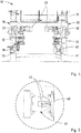
- the lower portion of the rail vehicle 13 is shown in detail, so in particular the chassis 30 and the inductive energy supply.
- the Fig. 5 shows only the essential elements of the dashed circle in the Fig. 4 marked area.
- the chassis 30 has a separate drive 33 for each of the wheels 32. These are shown here as independent electric drive motors.
- the chassis 30 itself is located below the actual chassis 31 and typically connected to it firmly.
- a bus bar 40 is provided on the rail section 12. This busbar 40 extends along the entire rail system 11 so as to be able to fully ensure the power supply.
- a corresponding current collector 41 is provided on the rail vehicle 13.
- busbars 40 may be provided on the rail system 11, for example on both sides of the respective rail section 12, 15, 21. Also, several current collectors 41 may be arranged on the rail vehicle 13 in order to avoid any interruptions in the power supply.
- the current collector 41 is U-shaped. It encompasses the busbar 40 from the side, so that in each case one of the pantograph legs 42 of the current collector 41 is arranged above or below the busbar 40. Thus, an optimal inductive coupling can be achieved.
- Bus bars 40 as well as pantographs 41 are each equipped with electrical conductors not shown here. These are in particular electrical coils. Thus, by applying electromagnetic alternating fields to the busbar 41 or the busbars 41, an inductive coupling from the busbar 41 to the pantograph or pantographs 41 takes place and so electrical energy is transmitted.
- the rail vehicle 13 is to transmit data in the direction of the rail system 11, it may be necessary to provide a corresponding feed in this direction. For example, this may be required for feedback to centralized or decentralized control devices. For example, status data or position data can be transmitted. If appropriate, however, corresponding data connections can also be established via radio links or the like, in particular via WLAN, Bluetooth or even NFC.
Landscapes
- Engineering & Computer Science (AREA)
- Mechanical Engineering (AREA)
- Power Engineering (AREA)
- Transportation (AREA)
- Computer Networks & Wireless Communication (AREA)
- Signal Processing (AREA)
- Life Sciences & Earth Sciences (AREA)
- Sustainable Development (AREA)
- Sustainable Energy (AREA)
- Platform Screen Doors And Railroad Systems (AREA)
- Electric Propulsion And Braking For Vehicles (AREA)
Applications Claiming Priority (1)
| Application Number | Priority Date | Filing Date | Title |
|---|---|---|---|
| DE102017120197.1A DE102017120197A1 (de) | 2017-09-01 | 2017-09-01 | Schienengebundenes Transportsystem, Schienensystem und Schienenfahrzeug für ein schienengebundenes Transportsystem |
Publications (2)
| Publication Number | Publication Date |
|---|---|
| EP3459781A2 true EP3459781A2 (fr) | 2019-03-27 |
| EP3459781A3 EP3459781A3 (fr) | 2019-06-26 |
Family
ID=63452541
Family Applications (1)
| Application Number | Title | Priority Date | Filing Date |
|---|---|---|---|
| EP18191988.7A Withdrawn EP3459781A3 (fr) | 2017-09-01 | 2018-08-31 | Système de transport ferroviaire, système ferroviaire et véhicule ferroviaire pour un système de transport ferroviaire |
Country Status (2)
| Country | Link |
|---|---|
| EP (1) | EP3459781A3 (fr) |
| DE (1) | DE102017120197A1 (fr) |
Cited By (5)
| Publication number | Priority date | Publication date | Assignee | Title |
|---|---|---|---|---|
| CN111038897A (zh) * | 2019-12-12 | 2020-04-21 | 广东三三智能科技有限公司 | 一种智能小车立体仓储系统 |
| CN112076480A (zh) * | 2019-06-14 | 2020-12-15 | 约瑟夫威根两合公司 | 用于运输至少一名乘员的系统 |
| WO2021013503A1 (fr) * | 2019-07-25 | 2021-01-28 | Siemens Mobility GmbH | Transfert de signal via une caténaire |
| CN113939971A (zh) * | 2019-05-23 | 2022-01-14 | 奥普蒂玛消费品有限公司 | 用于传输系统的能量供给模块、功能单元、系统、应用和装置 |
| CN115838059A (zh) * | 2022-12-07 | 2023-03-24 | 江苏威尔赛科技有限公司 | 一种拖车式医院轨道智能物流系统 |
Family Cites Families (12)
| Publication number | Priority date | Publication date | Assignee | Title |
|---|---|---|---|---|
| ATE18185T1 (de) * | 1980-12-19 | 1986-03-15 | Stig A Larsson | Transporteinrichtung fuer aufwickelbare strangfoermige gueter und ihre anwendung in einem integrierten transportsystem. |
| US5293308A (en) * | 1991-03-26 | 1994-03-08 | Auckland Uniservices Limited | Inductive power distribution system |
| JP3351264B2 (ja) * | 1996-10-16 | 2002-11-25 | 株式会社豊田自動織機 | 移動体の給電線重畳通信システム |
| DE19816768C2 (de) * | 1998-04-16 | 2002-06-27 | Mack Heinrich Gmbh & Co | Vorrichtung zum Transportieren von Achterbahnwagen |
| DE10159678B4 (de) * | 2001-12-05 | 2017-09-21 | Dürr Systems Ag | Schienengebundenes Transportsystem |
| DE20209542U1 (de) * | 2002-06-20 | 2002-09-12 | Bleichert Förderanlagen GmbH, 74706 Osterburken | Bodentransportsystem |
| DE10331778A1 (de) * | 2003-07-11 | 2005-02-10 | Siemens Ag | Innenläufer-Hängebahn mit induktiver Energieübertragung |
| DE102004031581B4 (de) * | 2004-06-29 | 2015-02-05 | Sew-Eurodrive Gmbh & Co Kg | Spurgeführtes Transportsystem |
| DE102005001117A1 (de) * | 2005-01-05 | 2006-07-13 | Menke, Wilhelm | Schiene für ein mobiles Transportsystem |
| DE102005051133B4 (de) * | 2005-10-26 | 2008-12-18 | Eisenmann Anlagenbau Gmbh & Co. Kg | Fahrerloses Transportsystem |
| DE202010004201U1 (de) * | 2010-03-25 | 2011-08-30 | Aloys Wobben | Transportsystem für eine Gießerei |
| WO2015069105A1 (fr) * | 2013-11-05 | 2015-05-14 | Ox2 B.V. | Dispositif et procédé de transport d'objets |
-
2017
- 2017-09-01 DE DE102017120197.1A patent/DE102017120197A1/de not_active Withdrawn
-
2018
- 2018-08-31 EP EP18191988.7A patent/EP3459781A3/fr not_active Withdrawn
Non-Patent Citations (1)
| Title |
|---|
| None |
Cited By (7)
| Publication number | Priority date | Publication date | Assignee | Title |
|---|---|---|---|---|
| CN113939971A (zh) * | 2019-05-23 | 2022-01-14 | 奥普蒂玛消费品有限公司 | 用于传输系统的能量供给模块、功能单元、系统、应用和装置 |
| US20220219920A1 (en) * | 2019-05-23 | 2022-07-14 | Optima consumer GmbH | Power supply module for a transport system, function unit, system, use, and arrangement |
| CN112076480A (zh) * | 2019-06-14 | 2020-12-15 | 约瑟夫威根两合公司 | 用于运输至少一名乘员的系统 |
| CN112076480B (zh) * | 2019-06-14 | 2023-03-03 | 约瑟夫威根两合公司 | 用于运输至少一名乘员的系统 |
| WO2021013503A1 (fr) * | 2019-07-25 | 2021-01-28 | Siemens Mobility GmbH | Transfert de signal via une caténaire |
| CN111038897A (zh) * | 2019-12-12 | 2020-04-21 | 广东三三智能科技有限公司 | 一种智能小车立体仓储系统 |
| CN115838059A (zh) * | 2022-12-07 | 2023-03-24 | 江苏威尔赛科技有限公司 | 一种拖车式医院轨道智能物流系统 |
Also Published As
| Publication number | Publication date |
|---|---|
| DE102017120197A1 (de) | 2019-03-07 |
| EP3459781A3 (fr) | 2019-06-26 |
Similar Documents
| Publication | Publication Date | Title |
|---|---|---|
| EP3459781A2 (fr) | Système de transport ferroviaire, système ferroviaire et véhicule ferroviaire pour un système de transport ferroviaire | |
| EP3274236B1 (fr) | Système de transport d'objets | |
| DE2440682C3 (de) | Umschlagsystem für Container und Paletten | |
| DE3136687C2 (de) | System, Betriebsverfahren und Vorrichtungen zum gleichzeitigen und rangierfreien Umschlag zwischen Schiene und Schiene sowie Strasse und Schiene | |
| EP3704000B1 (fr) | Procédé et véhicule permettant de transporter un véhicule automobile à propulsion électrique pendant son montage | |
| WO2015196221A1 (fr) | Installation de téléphérique | |
| AT509949B1 (de) | Speicherlager | |
| DE202013102852U1 (de) | Bearbeitungseinrichtung | |
| DE202017105290U1 (de) | Schienengebundenes Transportsystem, Schienensystem und Schienenfahrzeug für ein schienengebundenes Transportsystem | |
| DE102013018268A1 (de) | Transportsystem | |
| EP1925522A1 (fr) | Installation de transport à câble aérien dotée d'une station de stockage de véhicules | |
| AT504615A2 (de) | Vorrichtung zum speichern von fahrbetriebsmitteln einer seilbahnanlage in einem speicherbereich | |
| DE102017104751B4 (de) | Transportvorrichtung | |
| EP3455117B1 (fr) | Système de transport et chariot pour un système de transport | |
| DE4332232C1 (de) | Vorrichtung zum schnellen Umschlag von Transportbehältern | |
| EP2640619A1 (fr) | Dispositif de manipulation d'unités de transport transmodal | |
| DE102008047755A1 (de) | Vorrichtung und Verfahren zur Steuerung von Elektrohängebahnen | |
| DE102014226499A1 (de) | Fahrerloses Transportfahrzeug in einem Palettentransport-System | |
| DE3806347A1 (de) | Transportsystem | |
| EP2316716B1 (fr) | Dispositif de transport pour un dispositif de montage de véhicule | |
| WO2020115149A1 (fr) | Ensemble de stockage pourvu de systèmes de stockage disposés les uns à côté des autres et d'un système de préparation de commandes présentant des chariots de préparation de commande mobiles en va-et-vient | |
| DE1226389B (de) | Fuer auf Schienen verfahrbare Foerdergeraete bestimmte Einrichtung zum Zufuehren vonelektrischer Energie mit Hilfe von Kabeln | |
| DE477656C (de) | Verteilersystem fuer Fahrzeuge | |
| EP0336149B1 (fr) | Dispositif pour l'emmagasinage, l'alimentation et le traitement ultérieur de produits imprimés | |
| EP1189800A1 (fr) | Procede et dispositif pour transporter des charges |
Legal Events
| Date | Code | Title | Description |
|---|---|---|---|
| PUAI | Public reference made under article 153(3) epc to a published international application that has entered the european phase |
Free format text: ORIGINAL CODE: 0009012 |
|
| AK | Designated contracting states |
Kind code of ref document: A2 Designated state(s): AL AT BE BG CH CY CZ DE DK EE ES FI FR GB GR HR HU IE IS IT LI LT LU LV MC MK MT NL NO PL PT RO RS SE SI SK SM TR |
|
| AX | Request for extension of the european patent |
Extension state: BA ME |
|
| PUAL | Search report despatched |
Free format text: ORIGINAL CODE: 0009013 |
|
| AK | Designated contracting states |
Kind code of ref document: A3 Designated state(s): AL AT BE BG CH CY CZ DE DK EE ES FI FR GB GR HR HU IE IS IT LI LT LU LV MC MK MT NL NO PL PT RO RS SE SI SK SM TR |
|
| AX | Request for extension of the european patent |
Extension state: BA ME |
|
| RIC1 | Information provided on ipc code assigned before grant |
Ipc: B60L 9/00 20190101ALI20190523BHEP Ipc: B65G 54/02 20060101ALI20190523BHEP Ipc: H04B 5/00 20060101ALI20190523BHEP Ipc: B66C 7/12 20060101ALI20190523BHEP Ipc: B60M 1/32 20060101ALI20190523BHEP Ipc: B61B 13/00 20060101ALI20190523BHEP Ipc: B65G 1/04 20060101ALI20190523BHEP Ipc: B60L 5/39 20060101ALI20190523BHEP Ipc: B60L 5/00 20060101AFI20190523BHEP Ipc: H02J 50/10 20160101ALI20190523BHEP |
|
| STAA | Information on the status of an ep patent application or granted ep patent |
Free format text: STATUS: THE APPLICATION IS DEEMED TO BE WITHDRAWN |
|
| 18D | Application deemed to be withdrawn |
Effective date: 20200103 |