EP3459904B1 - Chariot de manutention, système hydraulique pour un chariot de manutention et procédé de fonctionnement d'un système hydraulique - Google Patents
Chariot de manutention, système hydraulique pour un chariot de manutention et procédé de fonctionnement d'un système hydraulique Download PDFInfo
- Publication number
- EP3459904B1 EP3459904B1 EP18194815.9A EP18194815A EP3459904B1 EP 3459904 B1 EP3459904 B1 EP 3459904B1 EP 18194815 A EP18194815 A EP 18194815A EP 3459904 B1 EP3459904 B1 EP 3459904B1
- Authority
- EP
- European Patent Office
- Prior art keywords
- mast
- lift cylinder
- hydraulic
- free
- lift
- Prior art date
- Legal status (The legal status is an assumption and is not a legal conclusion. Google has not performed a legal analysis and makes no representation as to the accuracy of the status listed.)
- Active
Links
Images

Classifications
-
- B—PERFORMING OPERATIONS; TRANSPORTING
- B66—HOISTING; LIFTING; HAULING
- B66F—HOISTING, LIFTING, HAULING OR PUSHING, NOT OTHERWISE PROVIDED FOR, e.g. DEVICES WHICH APPLY A LIFTING OR PUSHING FORCE DIRECTLY TO THE SURFACE OF A LOAD
- B66F9/00—Devices for lifting or lowering bulky or heavy goods for loading or unloading purposes
- B66F9/06—Devices for lifting or lowering bulky or heavy goods for loading or unloading purposes movable, with their loads, on wheels or the like, e.g. fork-lift trucks
- B66F9/075—Constructional features or details
- B66F9/20—Means for actuating or controlling masts, platforms, or forks
- B66F9/22—Hydraulic devices or systems
-
- B—PERFORMING OPERATIONS; TRANSPORTING
- B66—HOISTING; LIFTING; HAULING
- B66F—HOISTING, LIFTING, HAULING OR PUSHING, NOT OTHERWISE PROVIDED FOR, e.g. DEVICES WHICH APPLY A LIFTING OR PUSHING FORCE DIRECTLY TO THE SURFACE OF A LOAD
- B66F9/00—Devices for lifting or lowering bulky or heavy goods for loading or unloading purposes
- B66F9/06—Devices for lifting or lowering bulky or heavy goods for loading or unloading purposes movable, with their loads, on wheels or the like, e.g. fork-lift trucks
- B66F9/075—Constructional features or details
- B66F9/07504—Accessories, e.g. for towing, charging, locking
-
- B—PERFORMING OPERATIONS; TRANSPORTING
- B66—HOISTING; LIFTING; HAULING
- B66F—HOISTING, LIFTING, HAULING OR PUSHING, NOT OTHERWISE PROVIDED FOR, e.g. DEVICES WHICH APPLY A LIFTING OR PUSHING FORCE DIRECTLY TO THE SURFACE OF A LOAD
- B66F9/00—Devices for lifting or lowering bulky or heavy goods for loading or unloading purposes
- B66F9/06—Devices for lifting or lowering bulky or heavy goods for loading or unloading purposes movable, with their loads, on wheels or the like, e.g. fork-lift trucks
- B66F9/075—Constructional features or details
- B66F9/08—Masts; Guides; Chains
-
- F—MECHANICAL ENGINEERING; LIGHTING; HEATING; WEAPONS; BLASTING
- F15—FLUID-PRESSURE ACTUATORS; HYDRAULICS OR PNEUMATICS IN GENERAL
- F15B—SYSTEMS ACTING BY MEANS OF FLUIDS IN GENERAL; FLUID-PRESSURE ACTUATORS, e.g. SERVOMOTORS; DETAILS OF FLUID-PRESSURE SYSTEMS, NOT OTHERWISE PROVIDED FOR
- F15B11/00—Servomotor systems without provision for follow-up action; Circuits therefor
- F15B11/08—Servomotor systems without provision for follow-up action; Circuits therefor with only one servomotor
-
- F—MECHANICAL ENGINEERING; LIGHTING; HEATING; WEAPONS; BLASTING
- F15—FLUID-PRESSURE ACTUATORS; HYDRAULICS OR PNEUMATICS IN GENERAL
- F15B—SYSTEMS ACTING BY MEANS OF FLUIDS IN GENERAL; FLUID-PRESSURE ACTUATORS, e.g. SERVOMOTORS; DETAILS OF FLUID-PRESSURE SYSTEMS, NOT OTHERWISE PROVIDED FOR
- F15B2211/00—Circuits for servomotor systems
- F15B2211/40—Flow control
- F15B2211/405—Flow control characterised by the type of flow control means or valve
- F15B2211/40523—Flow control characterised by the type of flow control means or valve with flow dividers
- F15B2211/4053—Flow control characterised by the type of flow control means or valve with flow dividers using valves
-
- F—MECHANICAL ENGINEERING; LIGHTING; HEATING; WEAPONS; BLASTING
- F15—FLUID-PRESSURE ACTUATORS; HYDRAULICS OR PNEUMATICS IN GENERAL
- F15B—SYSTEMS ACTING BY MEANS OF FLUIDS IN GENERAL; FLUID-PRESSURE ACTUATORS, e.g. SERVOMOTORS; DETAILS OF FLUID-PRESSURE SYSTEMS, NOT OTHERWISE PROVIDED FOR
- F15B2211/00—Circuits for servomotor systems
- F15B2211/70—Output members, e.g. hydraulic motors or cylinders or control therefor
- F15B2211/71—Multiple output members, e.g. multiple hydraulic motors or cylinders
Definitions
- the invention relates to an industrial truck with a lift mast with at least one mast lift stage driven by at least one mast lift cylinder and with a free lift stage driven by at least one free lift cylinder, with which a load handling device can be moved along the lift mast. Furthermore, the invention relates to a hydraulic system for an industrial truck with a lifting mast with at least one mast lifting stage and with a free lifting stage, with which a load handling device can be moved along the lifting mast, the hydraulic system having at least one mast lifting cylinder for driving the at least one mast lifting step and at least one free lifting cylinder for Driving the at least one free lift stage comprises.
- the invention also relates to a method for operating a hydraulic system of an industrial truck with a lifting mast with at least one mast lifting step and with a free lifting step, with which a load handling device can be moved along the lifting mast, the hydraulic system having at least one Mast lift cylinder for driving the at least one mast lift stage and at least one free lift cylinder for driving the free lift stage.
- Known forklift trucks have a common hydraulic lowering branch for the mast lift and the free lift, in which a lowering valve is integrated. So that the mast lift steps and the free lift retract in the desired sequence when the load handling device is lowered, the individual mast lift steps and the free lift have hydraulic cylinders with different cross-sections. If several mast steps are extended, when the truck is in load lowering mode, the mast step whose total effective hydraulic cross-section is the smallest moves in first. The greatest hydraulic pressure is applied to this hydraulic cylinder, so that it retracts first when the hydraulic pressure drops. Usually it is the top mast lifting step. As the hydraulic pressure continues to fall, the mast steps become serial, that is one after the other, lowered. Finally, after the mast steps are fully retracted, the free lift step retracts and lowers the load handling device.
- a hydraulic system which comprises a free lift cylinder and a mast lift cylinder.
- a load handling device is coupled to the free lift cylinder, and a mast step is coupled to the mast lift cylinder.
- the two lifting cylinders are connected to a hydraulic tank via separate hydraulic return lines.
- a first return valve is provided in the first return line and a second return valve is provided in the second return line.
- the hydraulic fluid is supplied via a hydraulic pump, a supply valve and a first and a second connecting line. The supply of hydraulic fluid to the two lifting cylinders can take place at the same time.
- the supply valve is also a proportional valve
- the free lift and the mast lift can be moved independently of one another or together, depending on the valve position, to lift the load. It is also provided that shortly before the free lift cylinder reaches its end position, the feed valve is closed successively, so that the volume flow to the free lift cylinder is reduced. This document discloses the preamble of claim 1.
- an industrial truck with a lifting mast with at least one mast lifting stage driven by at least one mast lifting cylinder and with a free lifting stage driven by at least one free lifting cylinder, with which a load handling device can be moved along the lifting mast
- the industrial truck being further developed by a hydraulic system for supply the at least one mast lifting cylinder and the at least one free lifting cylinder with a hydraulic fluid
- the hydraulic system for at least temporarily actuating the at least one mast lifting cylinder and the at least one Free lift cylinder is set up in load lowering operation
- the hydraulic system for relieving the at least one mast lift cylinder and the at least one free lift cylinder in load lowering operation comprising separate hydraulic return lines
- the hydraulic system comprising a first hydraulic return line which runs between the at least one free lift cylinder and a reservoir for the hydraulic fluid
- the hydraulic system further comprises a second hydraulic return line, which runs between the at least one mast lifting cylinder and the storage container, wherein a first lowering valve is integrated into the first return line and a second lowering valve is integrated into the second
- the mast lifting steps and the load handling device are advantageously retracted and / or extended at the same time.
- the synchronous, i.e. H. At least temporarily simultaneous actuation of the at least one mast lifting cylinder and the at least one free lifting cylinder, the lowering time of the industrial truck can be reduced. This increases the handling capacity of the industrial truck. This applies if the truck reaches heights that can only be reached when the lifting mast is at least partially extended. In lifting operation, a jerky transition between free lift and mast lift can be avoided.
- An industrial truck or floor conveyor is a means of transport for the transport of goods, which is mostly used in-house and on the ground, for example a forklift.
- the industrial truck according to aspects of the invention is in load lowering mode when the load handling device is being lowered from the maximum height during the synchronous lowering process by the time span that is usually required to retract the load handling device with the free lift stage.
- the extension process ie the lifting of the load handling device to the maximum height, is more homogeneous and fluid than before. This improves the handling of the industrial truck.
- the lowering of the load handling device can be accelerated by simultaneously retracting the mast step (s) and the free lift step.
- the mast lift cylinder and the free lift cylinder can be relieved at the same time through the separate hydraulic return lines. This also applies if the mast lift cylinder and the free lift cylinder or the mast lift cylinder of the individual mast lift stages have different cross-sections, so that they extend in series, i.e. one after the other, in load lift operation. If only a single hydraulic line were also used to relieve the lifting cylinder, then the retraction of the mast lift stage and the free lift would necessarily take place in the reverse order to the extension. This is now advantageously no longer the case.
- the industrial truck is designed such that the hydraulic system comprises a first hydraulic return line that runs between the at least one free lift cylinder and a reservoir for the hydraulic fluid and the hydraulic system further comprises a second hydraulic return line that runs between the at least one mast lift cylinder and the reservoir , wherein a first lowering valve is integrated into the first return line and a second lowering valve is integrated into the second return line.
- the first lowering valve and the second lowering valve separately i. H. can be controlled independently of each other. It is thus possible to lower the mast lifting stage (s) and / or the load handling device separately and independently of one another in load lowering mode.
- the industrial truck comprises a controller which is set up to open the lowering valves at the same time when lowering the load handling device in load lowering mode.
- a controller which is set up to open the lowering valves at the same time when lowering the load handling device in load lowering mode.
- a displacement transducer is provided on the mast lift and on the free lift so that the respective speed at which the mast lift or the free lift is extended or retracted can be determined.
- a regulation is possible with which a uniform and homogeneous lowering process can be achieved, in particular so that the mast lifting stage and the load handling device reach their lower end position at least approximately simultaneously.
- the industrial truck is further developed in particular in that the hydraulic system comprises a hydraulic pump which is integrated in a hydraulic supply line and, in load lifting operation, is set up to apply pressurized hydraulic fluid to the at least one mast lifting cylinder and the at least one free lifting cylinder, the hydraulic supply line being forks between the hydraulic pump and the lifting cylinders into a first and a second supply branch and the first supply branch runs to the free lift cylinder and the second supply branch to the mast lift cylinder, with a lift valve designed as a proportional valve being integrated into the hydraulic supply line, with which a ratio between the volume flows is changeable in the first and in the second supply branch.
- the hydraulic system comprises a hydraulic pump which is integrated in a hydraulic supply line and, in load lifting operation, is set up to apply pressurized hydraulic fluid to the at least one mast lifting cylinder and the at least one free lifting cylinder, the hydraulic supply line being forks between the hydraulic pump and the lifting cylinders into a first and a second supply branch and the first supply branch runs to the free lift cylinder and the
- the free lift cylinder have a first cross section and the lift cylinder have a second cross section, the first cross section being larger than the second cross section and the lift valve being integrated into the first supply branch.
- the arrangement of the lift valve in the first supply branch is advantageous since the effective hydraulic flow cross-section of the first supply branch can be reduced by means of the lift valve. It is thus possible that the free lift cylinder and the lift cylinder can be extended at the same time by appropriate selection or adjustment of the effective hydraulic flow cross section of this supply branch.
- the control or control unit is in particular part of the operational control or operational control unit of the industrial vehicle.
- a hydraulic system for an industrial truck with a lifting mast with at least one mast lifting step and with a free lifting step with which a load handling device can be moved along the lifting mast the hydraulic system having at least one mast lifting cylinder for driving the at least one mast lifting step and at least one Comprises free lift cylinder for driving the at least one free lift stage
- the hydraulic system is further developed in that it is set up for at least temporarily simultaneously supplying the at least one mast lift cylinder and the at least one free lift cylinder with hydraulic fluid in load lowering mode
- the hydraulic system comprising a first hydraulic return line between the at least one free lift cylinder and a reservoir for the hydraulic fluid
- the hydraulic system further comprises a second separate hydraulic return line, which runs between the at least one mast lifting cylinder and the reservoir, a first lowering valve being integrated into the first return line and a second lowering valve being integrated into the second return line.
- the hydraulic system further comprises a hydraulic pump which is integrated in a hydraulic supply line and is set up in load lifting operation to pressurize the at least one mast lift cylinder and the at least one free lift cylinder with pressurized hydraulic fluid, the hydraulic supply line between the Hydraulic pump and the lifting cylinders forks into a first and a second supply branch and the first supply branch to the Free lift cylinder and the second supply branch runs to the mast lift cylinder, with a lift valve designed as a proportional valve being integrated into the hydraulic supply line, with which a ratio between the volume flows in the first and second supply branch can be changed.
- a hydraulic pump which is integrated in a hydraulic supply line and is set up in load lifting operation to pressurize the at least one mast lift cylinder and the at least one free lift cylinder with pressurized hydraulic fluid
- the hydraulic supply line between the Hydraulic pump and the lifting cylinders forks into a first and a second supply branch and the first supply branch to the Free lift cylinder and the second supply branch runs to the mast lift cylinder, with
- the object is also achieved by a method for operating a hydraulic system of an industrial truck with a lifting mast with at least one mast lifting step and with a free lifting step, with which a load handling device can be moved along the lifting mast, the hydraulic system having at least one mast lifting cylinder for driving the at least one mast lifting step and comprises at least one free lift cylinder for driving the free lift stage, the hydraulic system being developed in that it is operated in such a way that the at least one mast lift cylinder and the at least one free lift cylinder are operated at least temporarily simultaneously in load lift operation and / or load lowering operation, with the hydraulic System comprises a first hydraulic return line which runs between the at least one free lift cylinder and a reservoir for the hydraulic fluid and the hydraulic system further comprises a separate second hydraulic return line which between The at least one mast lifting cylinder and the storage container run, a first lowering valve being integrated into the first return line and a second lowering valve being integrated into the second return line, and the first lowering valve and the second lowering valve being opened at the same time in load lowering mode when the
- the hydraulic system comprises a hydraulic pump which is integrated in a hydraulic supply line and with which the at least one mast lift cylinder and the at least one free lift cylinder in load lift operation pressurized hydraulic fluid is applied, the hydraulic supply line forks between the hydraulic pump and the lifting cylinders in a first and a second supply branch and the first supply branch to the free lift cylinder and the second supply branch to the mast lift cylinder, with a lift valve designed as a proportional valve in the hydraulic supply line is integrated, with which a ratio between a volume flow in the first and in the second supply branch can be changed, wherein the free lift cylinder has a first cross section and the mast lift cylinder has a second cross section, the first cross section being larger than the second cross section and the lift valve in the first supply branch is integrated and wherein the lift valve is controlled in such a way that the free lift cylinder and the mast lift cylinder are extended at least temporarily at the same time.
- the lifting valve in a first position for a sequential extension of the free lift cylinder and the mast lift cylinder or in a second position for an at least temporarily simultaneous extension is brought.
- the corresponding operating mode can be selected manually, for example. However, it is also provided that a corresponding operating mode, in which the mast lift stage and the free lift stage are moved simultaneously, is selected if, for example, a lift height is entered manually which is outside the range that can only be reached by means of the free lift.
- Embodiments according to the invention can fulfill individual features or a combination of several features.
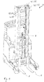
- Fig. 1 shows an industrial truck 2, for example a forklift, with a lifting mast 4, comprising, for example, a first mast lifting stage 41, the inner mast, and a second mast lifting stage 42, the central mast.
- the lifting mast 4 is supported by an in Fig. 1 Mast lifting cylinder (not shown, several mast lifting cylinders can also be provided) driven.
- the lifting mast 4 comprises, in addition to the inner mast and the central mast, a stationary mast firmly connected to the vehicle frame.
- the central mast is driven, for example, by the mast lifting cylinder, the inner mast is also coupled with the central mast, for example via a chain, so that these two extending masts extend at the same time.
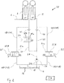
- Fig. 2 shows a schematic circuit diagram of a hydraulic system 10 as it is integrated in the industrial truck 2 according to an exemplary embodiment.
- the hydraulic system 10 is used to supply a mast lift cylinder 12 and the free lift cylinder 8, with which the load handling device 6 is moved, with a hydraulic fluid 14.
- the hydraulic fluid is taken from a reservoir 16 and also returned to it.
- the hydraulic system 10 is set up to simultaneously operate the mast lifting cylinder 12 and the free lifting cylinder 8 in the load lifting mode and / or in the lowering mode, at least at times.
- the hydraulic system 10 is set up to the mast lift cylinder 12 and the free lift cylinder 8 both in the load lifting operation, ie when lifting the Load suspension means 6, as well as in load lowering operation, that is, when lowering the load suspension means 6, to be actuated at the same time.
- the hydraulic system 10 comprises separate hydraulic return lines 18.
- a first hydraulic return line 181 runs between the free lift cylinder 8 and the storage container 16.
- a second hydraulic return line 182 is included, which runs between the mast lift cylinder 12 and the storage container 16.
- a first lowering valve 21 is integrated into the first return line 181 and a second lowering valve 22 is integrated into the second return line 182.
- the lowering valves 21, 22 are, for example, proportional valves. These can be switched between a first switching position 21a, 22a, in which the lowering valves 21, 22 work as check valves, and a second switching position 21b, 22b. In the second switching position 21b, 22b, the lowering valves 21, 22 are set up to control or regulate a first volume flow or a second volume flow.
- the first lowering valve 21 controls or regulates a first volume flow through the first return line 181, while the second lowering valve 22 controls or regulates a second volume flow through the second return line 182.
- the lowering valves 21, 22 can be controlled separately from one another.
- a controller 24 is included in the hydraulic system 10, which controls the two lowering valves 21, 22 via connecting lines (not shown).
- the controller 24 is set up or programmed in such a way that in a load lowering operation, ie when lowering the load handling device 6, the lowering valves 21, 22 open at the same time.
- the free lift cylinder 8 of the free lift stage and the mast lift cylinder 12 of the lift mast 4 are retracted at the same time.
- the load receiving means 6 actuated by the free lift stage sinks along the first mast lift stage 41, while at the same time the lift mast 4, ie the first and second mast lifting stage 41, 42, retract.
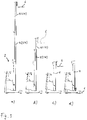
- FIG. 3a shows the industrial truck 2 with the lifting mast 4 fully extended.
- the load handling device 6 is located at the upper stop of the first mast lifting stage 41.
- a conventional industrial truck 2 comprises a common return line with which both the free lifting cylinder 8 and the mast lifting cylinder 12 are relieved of pressure.
- FIGS. 4a to 4c show a lowering process of a load handling device 6 of an industrial truck 2 according to an exemplary embodiment.
- Figure 4a shows the industrial truck 2 with the lifting mast 4 fully extended, with the load handling device 6 also being located at the upper stop of the first mast lifting step 41.
- This situation is identical to that in Fig. 3a shown.
- the in Fig. 4 illustrated industrial truck 2 the free lift stage and the mast lift stages 41, 42 by simultaneously opening the first and second lowering valve 21, 22 (cf. Fig. 2 ) lowered synchronously.
- Figure 4b shows the industrial truck 2 after a first time interval, after which the conventional industrial truck 2 in FIG Figure 3b is shown.
- the load handling device 6 has already reached the lower stop of the first mast lifting stage 41.
- the load handling device 6 is lowered significantly more quickly. Exactly that time interval is saved which the load suspension means 6 in a conventional industrial truck 2 needs in order to be lowered along a mast lifting step 41, 42.
- the hydraulic system 10 of the industrial truck 2 comprises a hydraulic pump 26 which draws hydraulic fluid 14 from the storage container 16 via a hydraulic supply line 28.
- the hydraulic pump 26 is integrated into the hydraulic supply line 28.
- the hydraulic pump 26 is used to pressurize the mast lifting cylinder 12 and the free lifting cylinder 8 with pressurized hydraulic fluid 14.
- the hydraulic supply line 28 forks between the hydraulic pump 26 and the lifting cylinders, ie the free lift cylinder 8 and the mast lift cylinder 12, into a first supply branch 31 and a second supply branch 32.
- the first supply branch 31 leads to the free lift cylinder 8
- the second supply branch 32 leads to the mast lifting cylinder 12.
- the two supply branches 31, 32 are also perceived as part of the hydraulic feed line 28.
- a lift valve 34 which can be designed as a proportional valve, is integrated into the first supply branch 31. Like the hydraulic pump 26, the lift valve 34 can be controlled or regulated via the controller 24.
- a ratio between the volume flows in the first and second supply branches 31, 32 can be changed via the settings of the lift valve 34.
- the free lift cylinder 8 has a first cross section and the mast lift cylinder 12 has a second cross section, the first cross section being larger than the second cross section. For this reason, the free lift cylinder 8 is activated at a first pressure p1, the pressure p1 being lower than the pressure p2 at which the mast lift cylinder 12 is activated.
- the effective hydraulic flow cross-section of the lifting cylinders 8, 12 can be variably adjusted via the settings of the lifting valve 34, so that it is possible to extend both lifting cylinders 8, 12 at the same time. This takes place in the first switch position 34a of the lift valve 34.
- the free lift can be blocked so that only the mast lift cylinder 12 is actuated.
- the dynamic setting of the lift valve 34 also makes it possible to achieve a smooth transition between a lift of the load-bearing means 6 effected by the free lift cylinder 8 and a lift of the same effected by the mast lift cylinder 12.
- a check valve 36 is integrated into the respective supply branch.
Landscapes
- Engineering & Computer Science (AREA)
- Structural Engineering (AREA)
- Transportation (AREA)
- Mechanical Engineering (AREA)
- Life Sciences & Earth Sciences (AREA)
- Geology (AREA)
- Civil Engineering (AREA)
- Chemical & Material Sciences (AREA)
- Combustion & Propulsion (AREA)
- Physics & Mathematics (AREA)
- Fluid Mechanics (AREA)
- General Engineering & Computer Science (AREA)
- Forklifts And Lifting Vehicles (AREA)
- Fluid-Pressure Circuits (AREA)
Claims (11)
- Chariot de manutention (2) comportant un mât de levage (4) ayant au moins un étage (41, 42) de levage de mât entraîné par au moins un vérin (12) de levage de mât et ayant un étage de levage libre entraîné par au moins un vérin (8) de levage libre, un moyen (6) de réception de charge étant apte à être déplacé le long du mât de levage (4) avec l'étage de levage libre, caractérisé par un système hydraulique (10) pour alimenter ledit au moins un vérin (12) de levage de mât et ledit au moins un vérin (8) de levage libre avec un fluide hydraulique (14), le système hydraulique (10) étant configuré pour l'actionnement simultané au moins temporaire dudit au moins un vérin (12) de levage de mât et dudit au moins un vérin (8) de levage libre lors d'une opération d'abaissement de la charge, le système hydraulique (10) comprenant des conduites de retour hydrauliques séparées (18) pour décharger ledit au moins un vérin (12) de levage de mât et ledit au moins un vérin (8) de levage libre lors d'une opération d'abaissement de la charge, le système hydraulique (10) comprenant une première conduite (181) de retour hydraulique qui s'étend entre ledit au moins un vérin (8) de levage libre et un réservoir (16) pour le fluide hydraulique (14), et le système hydraulique (10) comprend en outre une deuxième conduite (182) de retour hydraulique qui s'étend entre ledit au moins un vérin (12) de levage de mât et le réservoir (16), une première vanne d'abaissement (21) étant intégrée dans la première conduite de retour (181) et une deuxième vanne d'abaissement (22) étant intégrée dans la deuxième conduite de retour (182), et un système de commande (24) étant inclus, configuré pour ouvrir les deux vannes d'abaissement (21, 22) simultanément lors d'une opération d'abaissement de charge lorsque le moyen (6) de réception de charge est abaissé.
- Chariot de manutention (2) selon la revendication 1, caractérisé en ce que les vannes d'abaissement (21, 22) sont des vannes proportionnelles et le système de commande (24) est en outre agencé pour commander ou réguler un premier débit volumique à travers la première vanne d'abaissement (21) et un deuxième débit volumique à travers la deuxième vanne d'abaissement (22) de telle sorte que, lors d'une opération d'abaissement de la charge, lorsque le moyen (6) de réception de charge est abaissé, ledit au moins un étage (41, 42) de levage de mât et le moyen (6) de réception de charge atteignent une position finale inférieure d'une façon au moins approximativement simultanée.
- Chariot de manutention (2) selon la revendication 1 ou la revendication 2, caractérisé en ce que le système hydraulique (10) comprend une pompe hydraulique (26) qui est intégrée dans une conduite d'alimentation hydraulique (28) et qui, lors d'une opération de levage de la charge, est configurée pour agir sur ledit au moins un vérin (12) de levage de mât et ledit au moins un vérin (8) de levage libre avec un fluide hydraulique (14) sous pression, la conduite d'alimentation hydraulique (28) se divisant en une première et une deuxième branche d'alimentation (31, 32) entre la pompe hydraulique (26) et les vérins de levage (8, 12), la première branche d'alimentation (31) allant au vérin (8) de levage libre et la deuxième branche d'alimentation (32) allant au vérin de levage de mât (12), une vanne de levage (34) conçue sous la forme d'une vanne proportionnelle étant intégrée dans la conduite d'alimentation hydraulique (28) et un rapport entre les débits volumétriques dans la première et dans la deuxième branches d'alimentation (31, 32) étant apte à être modifié au moyen de cette vanne.
- Chariot de manutention (2) selon la revendication 3, caractérisé en ce que le vérin (8) de levage libre présente une première section transversale et le vérin de levage (12) présente une deuxième section transversale, la première section transversale étant plus grande que la deuxième section transversale et la vanne de levage (34) étant intégrée dans la première branche d'alimentation (31).
- Chariot de manutention (2) selon la revendication 3 ou la revendication 4, caractérisé par une commande (24) qui est configurée pour actionner la vanne de levage (34) de telle sorte que, lors d'une opération de levage de la charge, le vérin (8) de levage libre et le vérin (12) de levage de mât sont sortis simultanément, au moins par moments.
- Système hydraulique (10) pour un chariot de manutention (2) comportant un mât de levage (4) ayant au moins un étage (41, 42) de levage de mât et un étage de levage libre, au moyen duquel un moyen (6) de réception de charge est apte à être déplacé le long du mât de levage (4), le système hydraulique (10) comportant au moins un vérin (12) de levage de mât pour entraîner au moins un étage (41, 42) de levage de mât et au moins un vérin de levage libre (12), 42) et au moins un vérin (8) de levage libre pour entraîner ledit au moins un étage de levage libre, caractérisé en ce que le système hydraulique (10) est conçu pour alimenter simultanément, au moins par moments, ledit au moins un vérin (12) de levage de mât et ledit au moins un vérin (8) de levage libre avec un fluide hydraulique (14) lors d'une opération d'abaissement de charge, le système hydraulique (10) comprenant une première conduite (181) de retour hydraulique qui s'étend entre ledit au moins un vérin (8) de levage libre et un réservoir (16) pour le fluide hydraulique (14), et le système hydraulique (10) comprend en outre une deuxième conduite (182) de retour hydraulique séparée qui s'étend entre ledit au moins un vérin (12) de levage de mât et le réservoir (16), une première vanne d'abaissement (21) étant intégrée dans la première conduite de retour (181) et une deuxième vanne d'abaissement (22) étant intégrée dans la deuxième conduite de retour (182).
- Système hydraulique (10) selon la revendication 6, caractérisé en ce que le système hydraulique (10) comprend en outre une pompe hydraulique (26) qui est intégrée dans une conduite d'alimentation hydraulique (28) et qui, lors d'une opération de levage de charge, est conçue pour alimenter ledit au moins un vérin (12) de levage de mât et ledit au moins un vérin (8) de levage libre avec un fluide hydraulique (14) sous pression, la conduite d'alimentation hydraulique (28) se divisant en une première et une deuxième branche d'alimentation (31, 32) entre la pompe hydraulique (26) et les vérins de levage (8), 12) en une première et une deuxième branche d'alimentation (31, 32), la première branche d'alimentation (31) allant vers le vérin (8) de levage libre et la deuxième branche d'alimentation (32) allant vers le vérin (12) de levage de mât, une vanne de levage (34) qui est conçue sous la forme d'une vanne proportionnelle étant intégrée dans la conduite d'alimentation hydraulique (28), un rapport entre les débits volumiques dans la première et dans la deuxième branche d'alimentation (31, 32) étant apte à être modifié au moyen de cette vanne.
- Procédé pour faire fonctionner un système hydraulique (10) d'un chariot de manutention (2) comportant un mât de levage (4) ayant au moins un étage (41, 42) de levage de mât et un étage de levage libre, avec lequel un moyen (6) de réception de charge est apte à être déplacé le long du mât de levage (4), le système hydraulique (10) comprenant au moins un vérin (12) de levage de mât pour l'entraînement dudit au moins un étage (41, 42) de levage de mât, et au moins un vérin de levage libre (8) pour l'entraînement de l'étage de levage libre, caractérisé en ce que le système hydraulique (10) est conçu de telle sorte que, lors d'une opération d'abaissement de charge, ledit au moins un vérin (12) de levage de mât et ledit au moins un vérin (8) de levage libre sont actionnés simultanément, au moins par moments, le système hydraulique (10) comprenant une première conduite (181) de retour hydraulique qui s'étend entre ledit au moins un vérin (8) de levage libre et un réservoir (16) pour le fluide hydraulique (14) et le système hydraulique (10) comprenant en outre une deuxième conduite (182) de retour hydraulique séparée qui s'étend entre ledit au moins un vérin (12) de levage de mât et le réservoir (16), une première vanne d'abaissement (21) étant intégrée dans la première conduite de retour (181) et une deuxième vanne d'abaissement (22) étant intégrée dans la deuxième conduite de retour (182), et la première vanne d'abaissement (21) et la deuxième vanne d'abaissement (22) étant ouvertes simultanément lors d'une opération d'abaissement de la charge, lorsque le moyen (6) de réception de charge est abaissé.
- Procédé selon la revendication 8, caractérisé en ce que les vannes d'abaissement (21, 22) sont des vannes proportionnelles et un premier débit volumique est commandé ou régulé par la première vanne d'abaissement (21) et un deuxième débit volumique est commandé ou régulé par la deuxième vanne d'abaissement (22) de telle sorte que, lors de l'abaissement du moyen (6) de réception de charge, ledit au moins un étage (41, 42) de levage de mât et le moyen (6) de réception de charge atteignent une position finale inférieure d'une façon au moins approximativement simultanée.
- Procédé selon la revendication 8 ou la revendication 9, caractérisé en ce que le système hydraulique (10) comprend une pompe hydraulique (26) qui est intégrée dans une conduite d'alimentation hydraulique (28) et avec laquelle, lors d'une opération de levage de la charge, ledit au moins un vérin (12) de levage de mât et ledit au moins un vérin (8) de levage libre sont alimentés en fluide hydraulique (14) sous pression, la conduite d'alimentation hydraulique (28) se divisant entre la pompe hydraulique (26) et les vérins de levage (8, 12) en une première et une deuxième branche d'alimentation (31, 32), la première branche d'alimentation (31) allant vers le vérin (8) de levage libre et la deuxième branche d'alimentation (32) allant vers le vérin (12) de levage de mât, une vanne de levage (34) conçue sous la forme d'une vanne proportionnelle étant intégrée dans la conduite d'alimentation hydraulique (28), un rapport entre un débit volumique dans la première et dans la deuxième branche d'alimentation (31, 32) étant apte à être modifié au moyen de cette vanne, le vérin (8) de levage libre présentant une première section transversale et le vérin (12) de levage de mât présentant une deuxième section transversale, la première section transversale étant plus grande que la deuxième section transversale et la vanne de levage (34) étant intégrée dans la première branche d'alimentation (31) et la vanne de levage (34) étant commandée de telle sorte que le vérin (8) de levage libre et le vérin de levage du mât (12) sont sortis simultanément, au moins par moments.
- Procédé selon la revendication 10, caractérisé en ce que, en fonction d'un mode de fonctionnement du chariot de manutention (2) et/ou en fonction d'une hauteur de levage présélectionnée du moyen (6) de réception de charge, la vanne de levage (34) est amenée dans une première position pour une extension séquentielle du vérin (8) de levage libre et du vérin (12) de levage de mât ou dans une deuxième position pour une extension simultanée, au moins par moments.
Applications Claiming Priority (1)
| Application Number | Priority Date | Filing Date | Title |
|---|---|---|---|
| DE102017121818.1A DE102017121818B4 (de) | 2017-09-20 | 2017-09-20 | Flurförderzeug, hydraulisches System für ein Flurförderzeug und Verfahren zum Betreiben eines hydraulischen Systems |
Publications (3)
| Publication Number | Publication Date |
|---|---|
| EP3459904A1 EP3459904A1 (fr) | 2019-03-27 |
| EP3459904B1 true EP3459904B1 (fr) | 2021-08-04 |
| EP3459904B2 EP3459904B2 (fr) | 2024-09-11 |
Family
ID=63637736
Family Applications (1)
| Application Number | Title | Priority Date | Filing Date |
|---|---|---|---|
| EP18194815.9A Active EP3459904B2 (fr) | 2017-09-20 | 2018-09-17 | Chariot de manutention, système hydraulique pour un chariot de manutention et procédé de fonctionnement d'un système hydraulique |
Country Status (4)
| Country | Link |
|---|---|
| US (2) | US11427451B2 (fr) |
| EP (1) | EP3459904B2 (fr) |
| CN (1) | CN109534238B (fr) |
| DE (1) | DE102017121818B4 (fr) |
Families Citing this family (14)
| Publication number | Priority date | Publication date | Assignee | Title |
|---|---|---|---|---|
| DE102016124504A1 (de) * | 2016-12-15 | 2018-06-21 | Jungheinrich Aktiengesellschaft | Hubvorrichtung für ein Flurförderzeug sowie ein solches Flurförderzeug |
| DE102018117391A1 (de) | 2018-07-18 | 2020-01-23 | Jungheinrich Ag | Flurförderzeug mit einem hydraulischen System sowie Verfahren zum Betreiben eines hydraulischen Systems |
| USD940989S1 (en) * | 2019-05-17 | 2022-01-11 | Doosan Industrial Vehicle Co., Ltd. | Forklift |
| US20220356051A1 (en) * | 2019-05-28 | 2022-11-10 | Vehicle Service Group, Llc | Load-sensing vehicle lift |
| USD960484S1 (en) * | 2019-11-27 | 2022-08-09 | Hangzhou Hikrobot Technology Co., Ltd. | Forklift |
| KR102385239B1 (ko) * | 2020-06-19 | 2022-04-11 | 두산산업차량 주식회사 | 지게차 |
| JP1699646S (fr) * | 2020-08-07 | 2021-11-15 | ||
| USD981077S1 (en) * | 2020-12-17 | 2023-03-14 | Doosan Industrial Vehicle Co., Ltd. | Forklift |
| USD1021316S1 (en) * | 2021-10-18 | 2024-04-02 | Robopac S.P.A. | Lift truck |
| JP7729212B2 (ja) * | 2022-01-13 | 2025-08-26 | 株式会社豊田自動織機 | フォークリフトの荷役装置 |
| USD1021317S1 (en) * | 2022-05-03 | 2024-04-02 | Robopac S.P.A. | Lift truck |
| DE102022120009A1 (de) * | 2022-08-09 | 2024-02-15 | Linde Material Handling Gmbh | Hydraulisches System für ein Flurförderzeug |
| EP4624410A1 (fr) * | 2024-03-26 | 2025-10-01 | Toyota Material Handling Manufacturing Sweden AB | Procédé pour lever/abaisser un assemble de mât d'un véhicule de manutention de matériaux et véhicule de manutention de matériaux |
| US12600609B2 (en) | 2024-06-20 | 2026-04-14 | Mitsubishi Logisnext Americas Inc. | Hose supports for facilitating the assembly of masts for material handling vehicles and related methods |
Citations (10)
| Publication number | Priority date | Publication date | Assignee | Title |
|---|---|---|---|---|
| DE4305192A1 (fr) | 1992-02-20 | 1993-08-26 | Linde Ag | |
| EP1369377A2 (fr) | 2002-06-05 | 2003-12-10 | BT Industries | Procédé de commande pour chariot élévateur |
| EP1600420A1 (fr) | 2004-05-25 | 2005-11-30 | The Raymond Corporation | Mât à plusieurs étages et circuit hydraulique |
| WO2009141242A1 (fr) | 2008-05-23 | 2009-11-26 | Bt Products Ab | Chariot élévateur industriel avec commande de vitesse |
| DE102009011865A1 (de) | 2009-03-05 | 2010-09-16 | Jungheinrich Aktiengesellschaft | Hubvorrichtung für ein Flurförderzeug |
| US20110139546A1 (en) | 2008-08-27 | 2011-06-16 | Bt Products Ab | Hydraulic system for double stacker industrial truck |
| EP2465812A1 (fr) | 2010-12-16 | 2012-06-20 | BT Products AB | Camion industriel comportant un mât extensible |
| EP1593645B1 (fr) | 2004-05-03 | 2012-08-08 | Toyota Material Handling Europe AB | Appareil de levage hydraulique pour le mât télescopique d'un chariot élévateur à fourches |
| DE102016103256A1 (de) | 2015-12-29 | 2017-06-29 | Still Gmbh | Flurförderzeug mit einem Hubgerüst |
| EP3336051A1 (fr) | 2016-12-15 | 2018-06-20 | Jungheinrich Aktiengesellschaft | Dispositif de levage pour un chariot de manutention ainsi qu'un tel chariot de manutention |
Family Cites Families (6)
| Publication number | Priority date | Publication date | Assignee | Title |
|---|---|---|---|---|
| US3871266A (en) * | 1973-07-16 | 1975-03-18 | Hyster Co | Hydraulic cylinder phasing system |
| US5115720A (en) * | 1990-04-02 | 1992-05-26 | Baker Material Handling Corporation | Hydraulic valve bank |
| US5657834A (en) * | 1994-08-30 | 1997-08-19 | Crown Equipment Corporation | Mast staging cushion apparatus |
| DE102005050733A1 (de) * | 2005-10-22 | 2007-04-26 | Jungheinrich Ag | Hubmast für Stapler |
| DE102016124505A1 (de) * | 2016-12-15 | 2018-06-21 | Jungheinrich Aktiengesellschaft | Flurförderzeug mit einer Steuereinheit zur Regelung der Bewegung einer Kolbenstange eines Hydraulikzylinders sowie ein solches Verfahren |
| CA2998893A1 (fr) * | 2017-03-23 | 2018-09-23 | The Raymond Corporation | Systemes et methodes de stabilisation de mat sur un vehicule de transport de materiau |
-
2017
- 2017-09-20 DE DE102017121818.1A patent/DE102017121818B4/de active Active
-
2018
- 2018-09-17 EP EP18194815.9A patent/EP3459904B2/fr active Active
- 2018-09-17 US US16/132,568 patent/US11427451B2/en active Active
- 2018-09-20 CN CN201811096977.2A patent/CN109534238B/zh active Active
-
2022
- 2022-07-18 US US17/867,209 patent/US11905153B2/en active Active
Patent Citations (10)
| Publication number | Priority date | Publication date | Assignee | Title |
|---|---|---|---|---|
| DE4305192A1 (fr) | 1992-02-20 | 1993-08-26 | Linde Ag | |
| EP1369377A2 (fr) | 2002-06-05 | 2003-12-10 | BT Industries | Procédé de commande pour chariot élévateur |
| EP1593645B1 (fr) | 2004-05-03 | 2012-08-08 | Toyota Material Handling Europe AB | Appareil de levage hydraulique pour le mât télescopique d'un chariot élévateur à fourches |
| EP1600420A1 (fr) | 2004-05-25 | 2005-11-30 | The Raymond Corporation | Mât à plusieurs étages et circuit hydraulique |
| WO2009141242A1 (fr) | 2008-05-23 | 2009-11-26 | Bt Products Ab | Chariot élévateur industriel avec commande de vitesse |
| US20110139546A1 (en) | 2008-08-27 | 2011-06-16 | Bt Products Ab | Hydraulic system for double stacker industrial truck |
| DE102009011865A1 (de) | 2009-03-05 | 2010-09-16 | Jungheinrich Aktiengesellschaft | Hubvorrichtung für ein Flurförderzeug |
| EP2465812A1 (fr) | 2010-12-16 | 2012-06-20 | BT Products AB | Camion industriel comportant un mât extensible |
| DE102016103256A1 (de) | 2015-12-29 | 2017-06-29 | Still Gmbh | Flurförderzeug mit einem Hubgerüst |
| EP3336051A1 (fr) | 2016-12-15 | 2018-06-20 | Jungheinrich Aktiengesellschaft | Dispositif de levage pour un chariot de manutention ainsi qu'un tel chariot de manutention |
Also Published As
| Publication number | Publication date |
|---|---|
| DE102017121818B4 (de) | 2025-09-04 |
| US20220348447A1 (en) | 2022-11-03 |
| EP3459904A1 (fr) | 2019-03-27 |
| US11905153B2 (en) | 2024-02-20 |
| CN109534238B (zh) | 2022-01-04 |
| EP3459904B2 (fr) | 2024-09-11 |
| US11427451B2 (en) | 2022-08-30 |
| DE102017121818A1 (de) | 2019-03-21 |
| CN109534238A (zh) | 2019-03-29 |
| US20190084816A1 (en) | 2019-03-21 |
Similar Documents
| Publication | Publication Date | Title |
|---|---|---|
| EP3459904B2 (fr) | Chariot de manutention, système hydraulique pour un chariot de manutention et procédé de fonctionnement d'un système hydraulique | |
| EP1915538B1 (fr) | Montage pour commander un cylindre d'entrainement hydraulique a double effet | |
| EP3336051B1 (fr) | Dispositif de levage pour un chariot de manutention ainsi qu'un tel chariot de manutention | |
| AT399130B (de) | Anordnung zur hydraulischen betätigung eines fahrzeugverdeckes | |
| EP3159549B1 (fr) | Dispositif de recuperation d'energie hydraulique pour un engin de travail et engin de travail correspondant | |
| DE202014006861U1 (de) | Arbeitsmaschine | |
| DE10307993B4 (de) | Hebesteuerungs-bzw. Regelungssystem für eine Lasthebeeinrichtung sowie Verfahren zum Betrieb einer Lasthebevorrichtung | |
| DE19744429A1 (de) | Flurförderfahrzeug mit einer Lastaufnahmevorrichtung und Verfahren zum Absenken der Lastaufnahmevorrichtung | |
| DE2132842A1 (de) | Sicherheitseinrichtung fuer Hubstapler | |
| DE4234064C2 (de) | Rampenfläche zum Be- und Entladen einer insbesondere durch Seitenwände begrenzten Ladefläche eines Transportfahrzeuges | |
| DE19935854C2 (de) | Hydraulische Betätigungsanordnung | |
| DE2066194C2 (fr) | ||
| DE3640305A1 (de) | Hydraulik-antriebssystem fuer den gegenmassewagen eines gegenmassekrans | |
| WO2002076703A2 (fr) | Dispositif de serrage electromecanique | |
| EP4321471A1 (fr) | Système hydraulique pour un chariot de manutention | |
| DE3020432A1 (de) | Abbaumaschine zum abbauen von gestein oder mineral | |
| DE102008049135A1 (de) | Hydrauliksystem zum Verstellen von Flügel-Aufbauteilen eines Lkws | |
| DE3617080A1 (de) | Mehrstufige hydraulische kolben/zylindereinheit | |
| EP1967485B1 (fr) | Chariot de manutention | |
| EP4385938B1 (fr) | Dispositif de soupape pour un chariot de manutention | |
| DE3050174C2 (de) | Hydraulischer Steuerkreis eines hydraulisch betätigbaren Krans | |
| EP3597588B1 (fr) | Chariot de manutention doté d'un système hydraulique ainsi que procédé de fonctionnement d'un système hydraulique | |
| DE10063610A1 (de) | Eilgangsteuerung | |
| EP1911695A2 (fr) | Procédé de commande du synchronisme d'au moins deux cylindres de pression ainsi que commande de synchronisme | |
| DE19715224C2 (de) | Hydroseilaufzug |
Legal Events
| Date | Code | Title | Description |
|---|---|---|---|
| PUAI | Public reference made under article 153(3) epc to a published international application that has entered the european phase |
Free format text: ORIGINAL CODE: 0009012 |
|
| STAA | Information on the status of an ep patent application or granted ep patent |
Free format text: STATUS: THE APPLICATION HAS BEEN PUBLISHED |
|
| AK | Designated contracting states |
Kind code of ref document: A1 Designated state(s): AL AT BE BG CH CY CZ DE DK EE ES FI FR GB GR HR HU IE IS IT LI LT LU LV MC MK MT NL NO PL PT RO RS SE SI SK SM TR |
|
| AX | Request for extension of the european patent |
Extension state: BA ME |
|
| STAA | Information on the status of an ep patent application or granted ep patent |
Free format text: STATUS: REQUEST FOR EXAMINATION WAS MADE |
|
| 17P | Request for examination filed |
Effective date: 20190906 |
|
| RBV | Designated contracting states (corrected) |
Designated state(s): AL AT BE BG CH CY CZ DE DK EE ES FI FR GB GR HR HU IE IS IT LI LT LU LV MC MK MT NL NO PL PT RO RS SE SI SK SM TR |
|
| GRAP | Despatch of communication of intention to grant a patent |
Free format text: ORIGINAL CODE: EPIDOSNIGR1 |
|
| STAA | Information on the status of an ep patent application or granted ep patent |
Free format text: STATUS: GRANT OF PATENT IS INTENDED |
|
| INTG | Intention to grant announced |
Effective date: 20210428 |
|
| GRAS | Grant fee paid |
Free format text: ORIGINAL CODE: EPIDOSNIGR3 |
|
| GRAA | (expected) grant |
Free format text: ORIGINAL CODE: 0009210 |
|
| STAA | Information on the status of an ep patent application or granted ep patent |
Free format text: STATUS: THE PATENT HAS BEEN GRANTED |
|
| AK | Designated contracting states |
Kind code of ref document: B1 Designated state(s): AL AT BE BG CH CY CZ DE DK EE ES FI FR GB GR HR HU IE IS IT LI LT LU LV MC MK MT NL NO PL PT RO RS SE SI SK SM TR |
|
| REG | Reference to a national code |
Ref country code: GB Ref legal event code: FG4D Free format text: NOT ENGLISH |
|
| REG | Reference to a national code |
Ref country code: AT Ref legal event code: REF Ref document number: 1416809 Country of ref document: AT Kind code of ref document: T Effective date: 20210815 |
|
| REG | Reference to a national code |
Ref country code: CH Ref legal event code: EP |
|
| REG | Reference to a national code |
Ref country code: DE Ref legal event code: R096 Ref document number: 502018006406 Country of ref document: DE |
|
| REG | Reference to a national code |
Ref country code: IE Ref legal event code: FG4D Free format text: LANGUAGE OF EP DOCUMENT: GERMAN |
|
| REG | Reference to a national code |
Ref country code: SE Ref legal event code: TRGR |
|
| REG | Reference to a national code |
Ref country code: LT Ref legal event code: MG9D |
|
| REG | Reference to a national code |
Ref country code: NL Ref legal event code: MP Effective date: 20210804 |
|
| PG25 | Lapsed in a contracting state [announced via postgrant information from national office to epo] |
Ref country code: LT Free format text: LAPSE BECAUSE OF FAILURE TO SUBMIT A TRANSLATION OF THE DESCRIPTION OR TO PAY THE FEE WITHIN THE PRESCRIBED TIME-LIMIT Effective date: 20210804 Ref country code: BG Free format text: LAPSE BECAUSE OF FAILURE TO SUBMIT A TRANSLATION OF THE DESCRIPTION OR TO PAY THE FEE WITHIN THE PRESCRIBED TIME-LIMIT Effective date: 20211104 Ref country code: PT Free format text: LAPSE BECAUSE OF FAILURE TO SUBMIT A TRANSLATION OF THE DESCRIPTION OR TO PAY THE FEE WITHIN THE PRESCRIBED TIME-LIMIT Effective date: 20211206 Ref country code: NO Free format text: LAPSE BECAUSE OF FAILURE TO SUBMIT A TRANSLATION OF THE DESCRIPTION OR TO PAY THE FEE WITHIN THE PRESCRIBED TIME-LIMIT Effective date: 20211104 Ref country code: RS Free format text: LAPSE BECAUSE OF FAILURE TO SUBMIT A TRANSLATION OF THE DESCRIPTION OR TO PAY THE FEE WITHIN THE PRESCRIBED TIME-LIMIT Effective date: 20210804 Ref country code: HR Free format text: LAPSE BECAUSE OF FAILURE TO SUBMIT A TRANSLATION OF THE DESCRIPTION OR TO PAY THE FEE WITHIN THE PRESCRIBED TIME-LIMIT Effective date: 20210804 Ref country code: FI Free format text: LAPSE BECAUSE OF FAILURE TO SUBMIT A TRANSLATION OF THE DESCRIPTION OR TO PAY THE FEE WITHIN THE PRESCRIBED TIME-LIMIT Effective date: 20210804 Ref country code: ES Free format text: LAPSE BECAUSE OF FAILURE TO SUBMIT A TRANSLATION OF THE DESCRIPTION OR TO PAY THE FEE WITHIN THE PRESCRIBED TIME-LIMIT Effective date: 20210804 |
|
| PG25 | Lapsed in a contracting state [announced via postgrant information from national office to epo] |
Ref country code: PL Free format text: LAPSE BECAUSE OF FAILURE TO SUBMIT A TRANSLATION OF THE DESCRIPTION OR TO PAY THE FEE WITHIN THE PRESCRIBED TIME-LIMIT Effective date: 20210804 Ref country code: LV Free format text: LAPSE BECAUSE OF FAILURE TO SUBMIT A TRANSLATION OF THE DESCRIPTION OR TO PAY THE FEE WITHIN THE PRESCRIBED TIME-LIMIT Effective date: 20210804 Ref country code: GR Free format text: LAPSE BECAUSE OF FAILURE TO SUBMIT A TRANSLATION OF THE DESCRIPTION OR TO PAY THE FEE WITHIN THE PRESCRIBED TIME-LIMIT Effective date: 20211105 |
|
| PG25 | Lapsed in a contracting state [announced via postgrant information from national office to epo] |
Ref country code: NL Free format text: LAPSE BECAUSE OF FAILURE TO SUBMIT A TRANSLATION OF THE DESCRIPTION OR TO PAY THE FEE WITHIN THE PRESCRIBED TIME-LIMIT Effective date: 20210804 |
|
| REG | Reference to a national code |
Ref country code: DE Ref legal event code: R026 Ref document number: 502018006406 Country of ref document: DE |
|
| PG25 | Lapsed in a contracting state [announced via postgrant information from national office to epo] |
Ref country code: DK Free format text: LAPSE BECAUSE OF FAILURE TO SUBMIT A TRANSLATION OF THE DESCRIPTION OR TO PAY THE FEE WITHIN THE PRESCRIBED TIME-LIMIT Effective date: 20210804 |
|
| PLBI | Opposition filed |
Free format text: ORIGINAL CODE: 0009260 |
|
| REG | Reference to a national code |
Ref country code: CH Ref legal event code: PL |
|
| PLAB | Opposition data, opponent's data or that of the opponent's representative modified |
Free format text: ORIGINAL CODE: 0009299OPPO |
|
| PLAX | Notice of opposition and request to file observation + time limit sent |
Free format text: ORIGINAL CODE: EPIDOSNOBS2 |
|
| REG | Reference to a national code |
Ref country code: BE Ref legal event code: MM Effective date: 20210930 |
|
| 26 | Opposition filed |
Opponent name: STILL GMBH Effective date: 20220428 |
|
| PG25 | Lapsed in a contracting state [announced via postgrant information from national office to epo] |
Ref country code: SM Free format text: LAPSE BECAUSE OF FAILURE TO SUBMIT A TRANSLATION OF THE DESCRIPTION OR TO PAY THE FEE WITHIN THE PRESCRIBED TIME-LIMIT Effective date: 20210804 Ref country code: SK Free format text: LAPSE BECAUSE OF FAILURE TO SUBMIT A TRANSLATION OF THE DESCRIPTION OR TO PAY THE FEE WITHIN THE PRESCRIBED TIME-LIMIT Effective date: 20210804 Ref country code: RO Free format text: LAPSE BECAUSE OF FAILURE TO SUBMIT A TRANSLATION OF THE DESCRIPTION OR TO PAY THE FEE WITHIN THE PRESCRIBED TIME-LIMIT Effective date: 20210804 Ref country code: MC Free format text: LAPSE BECAUSE OF FAILURE TO SUBMIT A TRANSLATION OF THE DESCRIPTION OR TO PAY THE FEE WITHIN THE PRESCRIBED TIME-LIMIT Effective date: 20210804 Ref country code: EE Free format text: LAPSE BECAUSE OF FAILURE TO SUBMIT A TRANSLATION OF THE DESCRIPTION OR TO PAY THE FEE WITHIN THE PRESCRIBED TIME-LIMIT Effective date: 20210804 Ref country code: CZ Free format text: LAPSE BECAUSE OF FAILURE TO SUBMIT A TRANSLATION OF THE DESCRIPTION OR TO PAY THE FEE WITHIN THE PRESCRIBED TIME-LIMIT Effective date: 20210804 Ref country code: AL Free format text: LAPSE BECAUSE OF FAILURE TO SUBMIT A TRANSLATION OF THE DESCRIPTION OR TO PAY THE FEE WITHIN THE PRESCRIBED TIME-LIMIT Effective date: 20210804 |
|
| R26 | Opposition filed (corrected) |
Opponent name: STILL GMBH Effective date: 20220428 |
|
| PG25 | Lapsed in a contracting state [announced via postgrant information from national office to epo] |
Ref country code: LU Free format text: LAPSE BECAUSE OF NON-PAYMENT OF DUE FEES Effective date: 20210917 Ref country code: IE Free format text: LAPSE BECAUSE OF NON-PAYMENT OF DUE FEES Effective date: 20210917 Ref country code: BE Free format text: LAPSE BECAUSE OF NON-PAYMENT OF DUE FEES Effective date: 20210930 |
|
| PG25 | Lapsed in a contracting state [announced via postgrant information from national office to epo] |
Ref country code: SI Free format text: LAPSE BECAUSE OF FAILURE TO SUBMIT A TRANSLATION OF THE DESCRIPTION OR TO PAY THE FEE WITHIN THE PRESCRIBED TIME-LIMIT Effective date: 20210804 Ref country code: LI Free format text: LAPSE BECAUSE OF NON-PAYMENT OF DUE FEES Effective date: 20210930 Ref country code: CH Free format text: LAPSE BECAUSE OF NON-PAYMENT OF DUE FEES Effective date: 20210930 |
|
| PLBB | Reply of patent proprietor to notice(s) of opposition received |
Free format text: ORIGINAL CODE: EPIDOSNOBS3 |
|
| PG25 | Lapsed in a contracting state [announced via postgrant information from national office to epo] |
Ref country code: CY Free format text: LAPSE BECAUSE OF FAILURE TO SUBMIT A TRANSLATION OF THE DESCRIPTION OR TO PAY THE FEE WITHIN THE PRESCRIBED TIME-LIMIT Effective date: 20210804 |
|
| PG25 | Lapsed in a contracting state [announced via postgrant information from national office to epo] |
Ref country code: HU Free format text: LAPSE BECAUSE OF FAILURE TO SUBMIT A TRANSLATION OF THE DESCRIPTION OR TO PAY THE FEE WITHIN THE PRESCRIBED TIME-LIMIT; INVALID AB INITIO Effective date: 20180917 |
|
| P01 | Opt-out of the competence of the unified patent court (upc) registered |
Effective date: 20230628 |
|
| PG25 | Lapsed in a contracting state [announced via postgrant information from national office to epo] |
Ref country code: MK Free format text: LAPSE BECAUSE OF FAILURE TO SUBMIT A TRANSLATION OF THE DESCRIPTION OR TO PAY THE FEE WITHIN THE PRESCRIBED TIME-LIMIT Effective date: 20210804 |
|
| PG25 | Lapsed in a contracting state [announced via postgrant information from national office to epo] |
Ref country code: TR Free format text: LAPSE BECAUSE OF FAILURE TO SUBMIT A TRANSLATION OF THE DESCRIPTION OR TO PAY THE FEE WITHIN THE PRESCRIBED TIME-LIMIT Effective date: 20210804 |
|
| PUAH | Patent maintained in amended form |
Free format text: ORIGINAL CODE: 0009272 |
|
| STAA | Information on the status of an ep patent application or granted ep patent |
Free format text: STATUS: PATENT MAINTAINED AS AMENDED |
|
| 27A | Patent maintained in amended form |
Effective date: 20240911 |
|
| AK | Designated contracting states |
Kind code of ref document: B2 Designated state(s): AL AT BE BG CH CY CZ DE DK EE ES FI FR GB GR HR HU IE IS IT LI LT LU LV MC MK MT NL NO PL PT RO RS SE SI SK SM TR |
|
| REG | Reference to a national code |
Ref country code: DE Ref legal event code: R102 Ref document number: 502018006406 Country of ref document: DE |
|
| PG25 | Lapsed in a contracting state [announced via postgrant information from national office to epo] |
Ref country code: MT Free format text: LAPSE BECAUSE OF FAILURE TO SUBMIT A TRANSLATION OF THE DESCRIPTION OR TO PAY THE FEE WITHIN THE PRESCRIBED TIME-LIMIT Effective date: 20210804 |
|
| REG | Reference to a national code |
Ref country code: AT Ref legal event code: MM01 Ref document number: 1416809 Country of ref document: AT Kind code of ref document: T Effective date: 20230917 |
|
| REG | Reference to a national code |
Ref country code: SE Ref legal event code: RPEO |
|
| PG25 | Lapsed in a contracting state [announced via postgrant information from national office to epo] |
Ref country code: AT Free format text: LAPSE BECAUSE OF NON-PAYMENT OF DUE FEES Effective date: 20230917 |
|
| PG25 | Lapsed in a contracting state [announced via postgrant information from national office to epo] |
Ref country code: AT Free format text: LAPSE BECAUSE OF NON-PAYMENT OF DUE FEES Effective date: 20230917 |
|
| PGFP | Annual fee paid to national office [announced via postgrant information from national office to epo] |
Ref country code: DE Payment date: 20250919 Year of fee payment: 8 |
|
| PGFP | Annual fee paid to national office [announced via postgrant information from national office to epo] |
Ref country code: GB Payment date: 20250923 Year of fee payment: 8 |
|
| PGFP | Annual fee paid to national office [announced via postgrant information from national office to epo] |
Ref country code: FR Payment date: 20250922 Year of fee payment: 8 |
|
| PGFP | Annual fee paid to national office [announced via postgrant information from national office to epo] |
Ref country code: SE Payment date: 20250922 Year of fee payment: 8 |
|
| PGFP | Annual fee paid to national office [announced via postgrant information from national office to epo] |
Ref country code: IT Payment date: 20250930 Year of fee payment: 8 |
|
| PGFP | Annual fee paid to national office [announced via postgrant information from national office to epo] |
Ref country code: AT Payment date: 20260410 Year of fee payment: 5 |