EP3460162A1 - Cadre de fenêtre avec dispositif de fixation monolithique - Google Patents
Cadre de fenêtre avec dispositif de fixation monolithique Download PDFInfo
- Publication number
- EP3460162A1 EP3460162A1 EP18191805.3A EP18191805A EP3460162A1 EP 3460162 A1 EP3460162 A1 EP 3460162A1 EP 18191805 A EP18191805 A EP 18191805A EP 3460162 A1 EP3460162 A1 EP 3460162A1
- Authority
- EP
- European Patent Office
- Prior art keywords
- section
- wing
- fixing device
- opening
- frame
- Prior art date
- Legal status (The legal status is an assumption and is not a legal conclusion. Google has not performed a legal analysis and makes no representation as to the accuracy of the status listed.)
- Withdrawn
Links
- XLYOFNOQVPJJNP-UHFFFAOYSA-N water Substances O XLYOFNOQVPJJNP-UHFFFAOYSA-N 0.000 claims 2
- 239000000853 adhesive Substances 0.000 claims 1
- 230000001070 adhesive effect Effects 0.000 claims 1
- 238000003780 insertion Methods 0.000 claims 1
- 230000037431 insertion Effects 0.000 claims 1
- 238000000034 method Methods 0.000 claims 1
Images


Classifications
-
- E—FIXED CONSTRUCTIONS
- E06—DOORS, WINDOWS, SHUTTERS, OR ROLLER BLINDS IN GENERAL; LADDERS
- E06B—FIXED OR MOVABLE CLOSURES FOR OPENINGS IN BUILDINGS, VEHICLES, FENCES OR LIKE ENCLOSURES IN GENERAL, e.g. DOORS, WINDOWS, BLINDS, GATES
- E06B3/00—Window sashes, door leaves, or like elements for closing wall or like openings; Layout of fixed or moving closures, e.g. windows in wall or like openings; Features of rigidly-mounted outer frames relating to the mounting of wing frames
- E06B3/96—Corner joints or edge joints for windows, doors, or the like frames or wings
- E06B3/964—Corner joints or edge joints for windows, doors, or the like frames or wings using separate connection pieces, e.g. T-connection pieces
- E06B3/968—Corner joints or edge joints for windows, doors, or the like frames or wings using separate connection pieces, e.g. T-connection pieces characterised by the way the connecting pieces are fixed in or on the frame members
- E06B3/9684—Corner joints or edge joints for windows, doors, or the like frames or wings using separate connection pieces, e.g. T-connection pieces characterised by the way the connecting pieces are fixed in or on the frame members by hooking protrusions on the connecting piece in openings of the frame member, e.g. by snap-locking
- E06B3/9685—Mitre joints
-
- E—FIXED CONSTRUCTIONS
- E06—DOORS, WINDOWS, SHUTTERS, OR ROLLER BLINDS IN GENERAL; LADDERS
- E06B—FIXED OR MOVABLE CLOSURES FOR OPENINGS IN BUILDINGS, VEHICLES, FENCES OR LIKE ENCLOSURES IN GENERAL, e.g. DOORS, WINDOWS, BLINDS, GATES
- E06B3/00—Window sashes, door leaves, or like elements for closing wall or like openings; Layout of fixed or moving closures, e.g. windows in wall or like openings; Features of rigidly-mounted outer frames relating to the mounting of wing frames
- E06B3/96—Corner joints or edge joints for windows, doors, or the like frames or wings
- E06B3/964—Corner joints or edge joints for windows, doors, or the like frames or wings using separate connection pieces, e.g. T-connection pieces
- E06B3/968—Corner joints or edge joints for windows, doors, or the like frames or wings using separate connection pieces, e.g. T-connection pieces characterised by the way the connecting pieces are fixed in or on the frame members
- E06B3/9687—Corner joints or edge joints for windows, doors, or the like frames or wings using separate connection pieces, e.g. T-connection pieces characterised by the way the connecting pieces are fixed in or on the frame members with screws blocking the connecting piece inside or on the frame member
- E06B3/9688—Mitre joints
Definitions
- the present patent application for industrial invention relates to a window frame, in particular for shutters, provided with monolithic fixing device.
- shutters comprise a frame, which is made of sections that are fixed together in rectangular frame configuration, and a plurality of slates disposed between the sections.
- said sections comprise an upper crossbar, a lower crossbar and two uprights.
- the mounting method of the shutters provides for fixing the two uprights to the upper crossbar, inserting the slates between the two uprights and fixing the lower crossbar to the uprights.
- Each section comprises an external side that faces the exterior of the frame, and an internal side that faces the opening defined by the four sections of the frame.
- each section comprises an internal side that is suitable for facing the interior of the building, and an external side that is suitable for facing the exterior of the building.
- the sections are connected by means of fixing brackets disposed at the ends of the sections.
- said fixing brackets have an "L"-shape and comprise a first wing, which is suitable for being disposed inside a first section, and a second wing, which is suitable for being disposed inside the second section.
- Said fixing brackets can be monolithic fixing brackets and non-monolithic fixing brackets.
- Monolithic fixing brackets have low manufacturing costs, but are impaired by drawbacks related with their mounting inside the sections.
- the mounting method of the frame After connecting the uprights to the upper crossbar, the mounting method of the frame provides for mounting two brackets on the lower crossbar; each bracket is inserted with a first wing inside the end of the section, whereas the other wing is ready to be inserted inside one of the two vertical uprights.
- the lower crossbar is moved closer to the free ends of the uprights, in such a way as to permit the insertion of the wings that protrude from the lower crossbar in the empty spaces of the uprights.
- Adhesive is normally used to fix the wings to the sections. The use of the adhesive prevents the sections from being dismounted.
- the external side of the first section protrudes outwards relative to the external side of the second section, or vice versa.
- the internal side of a first section does not lie on the same plane as the internal side of a second section, causing the formation of a tooth.
- the frame When the sections are misaligned, in addition to being aesthetically impaired, the frame has sharp corners that may cut or hurt the user.
- Non-monolithic fixing brackets are usually more expensive than the monolithic ones, but are easier and quicker to mount compared to the monolithic fixing brackets. Moreover, non-monolithic brackets do not originate the aforementioned drawback related with the misalignment of the sections.
- Each wing of a non-monolithic bracket is fixed to the section by means of removable fixing means, such as buttons or screws.
- Each wing of the fixing bracket comprises a threaded hole and each section comprises a hole that is aligned with the hole of the wing of the fixing bracket, in such a way as to insert the screw of the fixing means in the hole of the wing when the fixing bracket is mounted in the section.
- the screw of the fixing means comprises a body that is screwed into the hole of the wing of the non-monolithic fixing bracket, and a head that is stopped against the section, in such a way as to fix the fixing bracket to the section.
- Such fixing brackets are normally provided with adjustment means to adjust the position of the fixing bracket after inserting the fixing bracket in the sections.
- the sections comprise openings that are suitable to permit the insertion of tools that cooperate with the adjustment means of the fixing bracket. Said openings are normally obtained on the external side of the section at the vertex formed by the two sections.
- a first drawback of the window frames provided with non-monolithic fixing brackets consists in the fact that the holes and/or the openings of the sections of the frame, which are necessary for the correct positioning and fixing of the fixing bracket in the sections, let the rain water penetrate inside the section.
- Such a drawback especially refers to the openings that are obtained in the upper crossbar. The rain water stagnates inside the section, damaging the section and the fixing bracket.
- a second drawback of said window frames consists in the fact that the holes and/or the openings of the sections are visible, impairing the aesthetics of the window frame.
- window frames for shutters are impaired by an additional drawback because of the fact that rain water can penetrate through a slot obtained on the internal side of the lower crossbar and suitable for housing the lower slate of the shutter. The rain water stagnates inside the slot, from which it cannot be ejected.
- the purpose of the present invention is to overcome the drawbacks of the prior art by disclosing a window frame provided with a fixing device that is inexpensive, easy to install in the sections and capable of ensuring the correct alignment of the sections, avoiding the stepped arrangement and the non-coplanarity of the sections.
- Another purpose is to disclose a window frame with sections wherein no penetration or stagnation of rain water is possible.
- An additional purpose is to disclose a window frame that is not provided with holes and/or visible openings, in such a way as to be aesthetically pleasant.
- Another purpose is to disclose a window frame without water stagnation inside the slot obtained on the lower crossbar of the frame.
- the window frame of the invention is defined by claim 1.
- the advantages of the window frame according to the present invention are manifest, wherein the provision of a first wing having a width in correspondence of the fixed peg that is lower than the maximum width of the first wing guarantees a simple, practical installation of the fixing device in the sections. Moreover, the provision of said fixing device avoids the misalignment of the sections after they are mounted.
- a window frame according to the invention is disclosed, which is generally indicated with reference numeral (100).
- the frame (100) comprises four sections (2, 2') connected together in frame-like configuration in such a way as to define a space. More precisely, the frame (100) comprises two first sections (2) in parallel position, and two second sections (2') in parallel position, which are perpendicular to the first sections (2).
- first sections (2) are uprights and the second sections (2') are crossbars.
- each section (2, 2') are inclined by 45° relative to the longitudinal axis of the section (2, 2').
- the end surface of a section (2) is stopped against the end surface of another section (2').
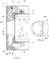
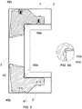
- Each section (2, 2') comprises a longitudinal empty space (3), which is shown in Figs. 4 and 5 , and two openings that provide access to the empty space (3) obtained at each end of the section (2, 2').
- Each section (2, 2') comprises an external wall (23) facing towards the exterior of the frame (100) and an internal wall (22) opposite to the external wall (23) and facing towards the space of the frame (100).
- each section (2, 2') comprises a transverse opening (21, 25) that provides access to the empty space (3).
- the opening (21) of the first section (2) is obtained on the internal wall (22) of the first section (2).
- the first section (2) has two openings (21) that are disposed at the ends of the first section (2).
- the opening (25) of the second section (2') is obtained in lower position on the second section (2'). More precisely, the second section (2') used as upper crossbar is provided with the opening (25) obtained on the internal wall (22) of the second section (2'). The second section (2') used as lower crossbar is provided with the opening (25) obtained on the external wall (23) of the second section (2').
- the sections (2, 2') are connected together by means of fixing devices (4) disposed in the empty spaces (3) of two consecutive sections in order to connect the two sections (2, 2').
- the frame (100) with four sections (2, 2') connected together in such a way as to form four corners comprises four fixing devices (4), one for each corner.
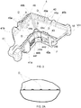
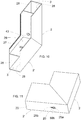
- the fixing device (4) is monolithic and comprises a first wing (40) disposed inside the empty space (3) of one of the two first sections (2), and a second wing (41) disposed inside the empty space (3) of one of the two second sections (2'). Being monolithic, the fixing device (4) is inexpensive and easy to make.
- Each wing (40, 41) comprises an internal surface (40a, 41a) disposed in contact with the internal wall (22) of the section (2, 2'), and an external surface (40b, 41b) disposed in contact with the external wall (23) of the section (2, 2').
- Each wing (40, 41) comprises a first surface (45a, 46a), which is shown in Fig. 2 , and a second surface (45b, 46b), which is shown in Fig. 3 , which are parallel and perpendicular to the internal surfaces (40a, 41a) and to the external surfaces (40b, 41 b) of the corresponding wing (40,41).
- the wings (40, 41) are disposed in such a way as to form a corner (49). More precisely, the wings (40, 41) form an external corner (49b) in the junction between the external surfaces (40b, 41b) of the wings (40, 41) and form an internal corner (49a) in the junction between the internal surfaces (40a, 41a) of the wings (40, 41).
- the external surface (40b) of the first wing (40) and the external surface (41b) of the second wing (41) form an external obtuse corner ( ⁇ )
- the internal surface (40a) of the first wing (40) and the internal surface (41a) of the second wing (41) form an internal corner ( ⁇ ).
- the first wing (40) advantageously comprises:
- the second inlet (44d) is advantageously provided with a lower radius of curvature than the first inlet (44c).
- the second wing (41) comprises:
- the second inlet (44f) of the second wing (41) advantageously has a radius of curvature that is higher than the first inlet (44e) of the second wing (41) and is equal to the radius of curvature of the first inlet (44c) of the first wing (40). Moreover, advantageously, the first inlet (44e) of the second wing (41) has the same radius of curvature as the second inlet (44d) of the first wing (40).
- first inlets (44c, 44e) of the two wings (40, 41) are joined in such a way as to form a first counter-surface (44a) disposed on the internal surface (41a) of the second wing (41), and the second inlets (44d, 44f) of the two wings (40, 41) are joined in such a way as to form a second counter-surface (44b) disposed on the internal surface (40a) of the first wing (40).
- the counter-surfaces (44a, 44b) permit the correct positioning of the fixing device inside the sections (2, 2'). As shown in Fig. 9A , when the fixing device (4) is fixed to the sections (2, 2'), the first counter-surface (44a) is stopped against the internal wall of the second section (2'), whereas the second counter-surface (44b) is stopped against the internal wall of the first section (2). In view of the above, the two counter-surfaces (44a, 44b) of the fixing device (4) block the corner formed by the junction between the internal walls (22) of the two sections (2, 2'), in such a way that the sections (2, 2') are disposed at right angle.
- each wing may comprise only one inlet, which is joined with the inlet of the other wing to form the counter-surfaces.
- the fixing device (4) comprises a fixed peg (43) that protrudes from the internal surface (40a) of the first wing (40) and is disposed in the opening (21) of the first section (2).
- the fixed peg (43) fixes the first wing (40) to the first section (2).
- the first wing (40) has a section (48) that extends after the fixed peg (43), going from the corner (49) towards the fixed peg (43).
- said section (48) is an ending section of the wing.
- said section (48) may not be an ending section and may be followed by one or more additional sections.
- the first wing (40) has a variable width. It must be noted that the term “width” indicates the distance between the internal surface (40a) and the external surface (40b) of the first wing (40) and the term “variable” means that the width of the first wing (40) is not constant.
- the first wing (40) has at least one section with a minimum width and at least one section with a maximum width, which is slightly lower than the width of the empty space (3) of the first section (2).
- the internal surface (40a) and the external surface (40b) of the first wing (40) can have a curvilinear profile and/or a profile formed of broken lines that are joined together in such a way as to define sections with minimum width and sections with maximum width.
- the external surface (40a) of the first wing (40) is smooth and the first wing (40) has a tapered shape going towards the corner (49).
- the first wing (40) has its maximum width in the ending section (48) and has a width in correspondence of the fixed peg (43) that is lower to the maximum width of the first wing (40).
- the first wing (40) can be inserted in the first section (2) in spite of the fact that the fixed peg (43) protrudes from the first wing (40).
- the first wing (40) is provided with two notches (43a) that are obtained on the internal surface (40a) of the first wing (40) and are suitable for permitting the correct positioning of the fixing device (4) inside the empty spaces (3) of the sections (2, 2').
- the second wing (41) has a variable width.
- the second wing (41) has at least one section with a minimum width and at least one section with a maximum width, which is slightly lower than the width of the empty space (3) of the second section (2').
- the internal surface (41a) and the external surface (41b) of the second wing (41) can have a curvilinear profile and/or a profile formed of broken lines that are joined together in such a way as to define sections with minimum width and sections with maximum width.
- the second wing (41) has a maximum width near the corner (49) of the fixing device and has a minimum width in its ending section.
- the second wing (40) can be inserted in the first section (2) and can be moved in such a way as to position the fixing device (4) correctly inside the sections (2, 2').
- the fixing device (4) advantageously comprises removable teeth (D) that protrude from the first surface (45a, 46a) and from the second surface (45b, 46b) of each wing (40, 41) to compensate for the difference in height between the wings (40, 41) and the empty space (3) of the sections (2, 2').
- said teeth (D) are disposed on the edges of the wings (40, 41) and in the corner (49) of the fixing device (4).
- the teeth (D) disposed on the edges of the wings (40, 41) are aligned in rows. As shown in Fig. 2A , the teeth (D) of each row have a decreasing height going from the corner (49) towards the ends of each wing (40, 41).
- said teeth can be partially or totally removed because of the sliding movement of the walls of the fixing device (4) against the internal surfaces (28) of a front wall and/or of a back wall of the sections (2, 2'), as shown in Fig. 10 .
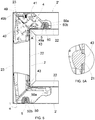
- the window frame (100) comprises fixing means (5) for fixing the second wing (41) to the second section (2').
- the fixing means (5) can be of any type, such as for example nails or anchor plugs.
- the fixing means (5) comprise screws (50).
- Each screw (50) is screwed in a threaded hole (47) obtained in the second wing (41) of the fixing device (4), as shown in Figs. 3 and 4 .
- the threaded hole (47) is a so-called “slotted" hole, meaning that, in addition to being provided with an axial opening for the screw (50), said threaded hole (47) is also provided with a radial opening that ends in the second surface (45b, 46b) of each wing (40, 41).
- the width of the radial opening is equal to the internal diameter of the threaded hole (47), in such a way to screw the screw (50) firmly inside the threaded hole (47) and at the same time simplify the molding of the fixing device (4).
- the threaded hole (47) of the second wing (2) is suitable for being aligned with the opening (25) of the second section (2').
- the screw (50) has a threaded body (50a) that is screwed in the threaded hole (47) of the second wing (41), and a head (50b) positioned inside the opening (25) of the second section (2') and flush with a surface of the second section (2').
- the opening (25) of the second section (2') advantageously comprises a hole (25a) crossed by the threaded body (50a) of the screw (50) of the fixing means (5), and a notch (25b) that ends in the hole (25a) of the opening (25) of the second section (2').
- the notch (25b) permits the insertion of a tool that collaborates with the fixing device (4) for moving the fixing device inside the sections (2, 2').
- the second wing (41) advantageously comprises a first threaded hole obtained on the internal surface (41a) of the second wing (41) and a second threaded hole obtained on the external surface (41b) of the second wing (41).
- the fixing device (4) can be used for fixing the uprights to the lower crossbar and to the upper crossbar.
- the second threaded hole of the second wing (41) is aligned with the hole (25a) of the opening (25) of the second section (2') that is obtained on the external wall (23) of the second section (2').
- the screw (50) is screwed under the lower crossbar until it is flush with the external wall (23) of the second section (2'). In view of the above, the screw (50) is not visible.
- the first threaded hole of the second wing (41) is aligned with the hole (25a) of the opening (25) of the second section (2') that is obtained on the internal wall (22) of the second section (2').
- the screw (50) is screwed under the upper crossbar until it is flush with the internal wall (22) of the second section (2').
- the screw (50) is not visible because the screw (50) is covered with slates or with a glass, which are suitable for being disposed in the space of the frame (100).
- the provision of an opening (25) obtained on the internal wall (22) of the second section (2'), which is suitable for acting as upper crossbar prevents the rain water from penetrating inside the second section (2').
- the fixing devices of the first type comprise a threaded hole that is obtained on the internal surface of the second wing and are suitable for being disposed inside the upper crossbar.
- the fixing devices of the second type comprise a threaded hole that is obtained on the external surface of the second wing and are suitable for being disposed inside the lower crossbar.
- the second section (2') used as lower crossbar comprises a slot (26) that is obtained on the internal wall (22) of the second section (2').
- a slot (26) is suitable for housing a lower slate, when the window frame (100) is used for a shutter.
- Such a second section (2') comprises an additional opening (27) that is obtained on the internal wall (22) of the second section (2') in correspondence of the slot (26).
- the additional opening (27) permits the entrance of the water contained in the slot (26) into the empty space (3) of the second section (2').
- Such water comes out of the empty space (3) of the second section (2') through the notch (25b) of the opening (25) of the second section (2').
- the hole (25a) of the opening (25) of the second section (2') is closed by the head of the screw (50), whereas the notch (25b) is free to let the water out from the empty space (3) of the second section (2').
- the mounting method of the window frame (100) provides for inserting the second wing (41) of the fixing device (4) in the empty space (3) of the second section (2').
- the second wing (41) of the fixing device (4) is disposed in such a way that one of the two threaded holes (47) is proximal to the opening (25) of the second section (2'), whereas the other threaded hole (47) is disposed on the opposite surface of the second wing (41).
- the first wing (40) of the fixing device (4) is inserted in the empty space (3) of the first section (2) by moving the sections (2, 2') closer until the two sections (2, 2') are stopped one against the other.
- the fixed peg (43) of the fixing device (4) is proximal to the opening (21) of the first section (2), as shown in Fig. 4A .
- the ending section (48) of the first wing (40) is stopped both against the internal wall (22) and the external wall (23) of the first section (2). Because of the variable width of the first wing (40) and, more precisely, because of the fact that the width of the first wing (40) in the peg (43) is lower than the maximum width of the first wing (40), the peg (43) can be disposed inside the empty space (3).
- the fixing device (4) is disposed inside the sections (2, 2') in such a way that the longitudinal axis of the first wing is parallel to the longitudinal axis of the first section (2), whereas the longitudinal axis of the second wing (41) is oblique relative to the longitudinal axis of the second section (2').
- the fixing device When connecting the two uprights to the upper crossbar, the fixing device can be installed in the sections either by inserting first the first wing in the first section and then the second wing in the second section, or by disposing first the second wing in the second section and then the first wing in the first section.
- a tool such as a screwdriver, is disposed in the notch (25b) of the opening (25) of the second section (2'), in such a way that the tool intercepts the second wing (41) of the fixing device (4). More precisely, the tool is inserted in the threaded hole (47) of the second wing (41) in proximal position to the opening (25) of the second section (2').
- the walls that define the threaded hole (47) of the second wing (41) act as counter-surface for the tool.
- the second wing (41) can be provided with depressions or teeth that act as counter-surfaces for the tool.
- the tool is moved in such a way as to align the threaded hole (47) of the second wing (41) with the hole (25a) of the opening (25) of the second section (2'), as shown in Figs. 5 , 7 and 9 .
- Such a movement of the tool determines a rotation of the fixing device (4) inside the sections (2, 2') around an internal edge (F) of an ending wall of the first wing (40).
- Such an internal edge (F) acts as pivoting peg for the rotation of the fixing device (4).
- the fixing device (4) rotates until the internal surface (40a) of the first wing (40) is stopped against the internal wall (22) of the first section (2); preferably, the fixing device (4) rotates by an angle comprised between 5° and 30°.
- the fixed peg (43) is disposed inside the opening (21) of the first section (2), fixing the first wing (40) to the first section (4), as shown in Fig. 5A .
- the fixed peg (43) While positioning inside the opening (21) of the first section (2), the fixed peg (43) is stopped against the walls that define the opening (21) of the first section (2), and pushes the first section (2) towards the second section (2').
- the fixing device (4) is disposed in such a way that the longitudinal axis of the first wing (40) is oblique relative to the longitudinal axis of the first section (2), whereas the longitudinal axis of the second wing (41) is parallel to the longitudinal axis of the second section (2').
- the second wing (41) of the fixing device (4) is fixed to the second section (2') by means of the fixing means (5), tightening the screw in the threaded hole (47) of the second wing (41) that is aligned with the hole (25a) of the opening (25) of the second section (2').
- the installation of the fixing device (4) in the sections (2, 2') is easy and practical. Moreover, the provision of said fixing device (4) avoids the problem of misalignment. More precisely, the problem of a stepped arrangement is avoided thanks to the counter-surfaces (44a, 44b) of the wings (40, 41) of the fixing device (4), which guarantee the correct mutual position of the sections (2, 2'). Moreover, the problem of non-coplanarity is avoided thanks to the teeth (D) that protrude from the first surface (45a, 46a) and from the second surface (45b, 46b) of the wings (40, 41) of the fixing device (4).
- the frame may comprise two or three sections that are fixed together and connected to another element.
Landscapes
- Engineering & Computer Science (AREA)
- Civil Engineering (AREA)
- Structural Engineering (AREA)
- Wing Frames And Configurations (AREA)
Applications Claiming Priority (1)
| Application Number | Priority Date | Filing Date | Title |
|---|---|---|---|
| IT201700105971 | 2017-09-21 |
Publications (1)
| Publication Number | Publication Date |
|---|---|
| EP3460162A1 true EP3460162A1 (fr) | 2019-03-27 |
Family
ID=61006212
Family Applications (1)
| Application Number | Title | Priority Date | Filing Date |
|---|---|---|---|
| EP18191805.3A Withdrawn EP3460162A1 (fr) | 2017-09-21 | 2018-08-30 | Cadre de fenêtre avec dispositif de fixation monolithique |
Country Status (1)
| Country | Link |
|---|---|
| EP (1) | EP3460162A1 (fr) |
Citations (3)
| Publication number | Priority date | Publication date | Assignee | Title |
|---|---|---|---|---|
| DE3900609A1 (de) * | 1989-01-11 | 1990-07-12 | Langenhorst Guenter | Rahmen aus auf gehrung gestossenen rahmenteilen, die in eine wandoeffnung einzusetzen sind, insbesondere tuerrahmen, fensterrahmen o. dgl. |
| WO2000045681A1 (fr) * | 1999-02-03 | 2000-08-10 | Weltec B.V. | Joint d'angle et notamment assemblage a onglet entre deux elements cadre |
| WO2014122181A1 (fr) * | 2013-02-08 | 2014-08-14 | L.M. Dei F.Lli Monticelli - S.R.L. | Carré de serrage amélioré à broches fixes pour raccordement angulaire de sections |
-
2018
- 2018-08-30 EP EP18191805.3A patent/EP3460162A1/fr not_active Withdrawn
Patent Citations (3)
| Publication number | Priority date | Publication date | Assignee | Title |
|---|---|---|---|---|
| DE3900609A1 (de) * | 1989-01-11 | 1990-07-12 | Langenhorst Guenter | Rahmen aus auf gehrung gestossenen rahmenteilen, die in eine wandoeffnung einzusetzen sind, insbesondere tuerrahmen, fensterrahmen o. dgl. |
| WO2000045681A1 (fr) * | 1999-02-03 | 2000-08-10 | Weltec B.V. | Joint d'angle et notamment assemblage a onglet entre deux elements cadre |
| WO2014122181A1 (fr) * | 2013-02-08 | 2014-08-14 | L.M. Dei F.Lli Monticelli - S.R.L. | Carré de serrage amélioré à broches fixes pour raccordement angulaire de sections |
Similar Documents
| Publication | Publication Date | Title |
|---|---|---|
| US3654734A (en) | Adjustable door or window frame | |
| US4813204A (en) | Adjustable door jamb assembly | |
| US4250673A (en) | Window replacement system | |
| PL201510B1 (pl) | Złącze teowe pomiędzy szczebliną i słupkiem elewacji lub dachu świetlikowego | |
| GB2109850A (en) | Method of installing a replacement door or window frame on an existing sub-frame | |
| US5295327A (en) | Sheet metal door frame and a method for installing the same in a doorway | |
| RU2089713C1 (ru) | Система соединения профильных элементов дверей и окон, способ соединения пары профилей и рама дверей и окон | |
| EP3460162A1 (fr) | Cadre de fenêtre avec dispositif de fixation monolithique | |
| EP3121363A1 (fr) | Équerre de fixation pour cadres constitués de profilés | |
| UA53727C2 (uk) | Розташування деталі набору | |
| EP2832276A1 (fr) | Ensemble de porte | |
| GB2313857A (en) | A method of attaching solar shading to curtain walling | |
| EP1722063A2 (fr) | Dispositif pour le montage des châssis | |
| JP5085884B2 (ja) | ふかし枠、及び、建具 | |
| EP2322737A2 (fr) | Ensemble de lattes de finition pour ouverture de construction | |
| JP7061957B2 (ja) | 建具 | |
| EP3587721A1 (fr) | Fenêtre, porte ou persienne pour zones extérieures, procédé de montage correspondant et ensemble de verrouillage pour verrouiller un panneau sur un cadre porteur de ladite fenêtre, porte ou persienne | |
| US6138428A (en) | Cladding for windows and/or doors | |
| EP4234876A1 (fr) | Procédé d'installation d'un pare-soleil dans une ouverture de lumière d'un élément de construction et élément de construction | |
| US12049785B2 (en) | Window frame ventilator | |
| EP3982802B1 (fr) | Appareil de couplage réglable et procédé de couplage d'un écran ou d'un panneau à une structure | |
| KR200438907Y1 (ko) | 창호틀 셋팅블럭 | |
| JP7101603B2 (ja) | 建具 | |
| AU2003231324A1 (en) | A kit for the construction of a frame for a door or window | |
| GB2363155A (en) | Wedge shaped member for use in sub frames for bay windows |
Legal Events
| Date | Code | Title | Description |
|---|---|---|---|
| PUAI | Public reference made under article 153(3) epc to a published international application that has entered the european phase |
Free format text: ORIGINAL CODE: 0009012 |
|
| AK | Designated contracting states |
Kind code of ref document: A1 Designated state(s): AL AT BE BG CH CY CZ DE DK EE ES FI FR GB GR HR HU IE IS IT LI LT LU LV MC MK MT NL NO PL PT RO RS SE SI SK SM TR |
|
| AX | Request for extension of the european patent |
Extension state: BA ME |
|
| STAA | Information on the status of an ep patent application or granted ep patent |
Free format text: STATUS: THE APPLICATION IS DEEMED TO BE WITHDRAWN |
|
| 18D | Application deemed to be withdrawn |
Effective date: 20190928 |