EP3460219A1 - Turbomachine avec une boîte de vitesses et ensemble de machine électrique intégré - Google Patents
Turbomachine avec une boîte de vitesses et ensemble de machine électrique intégré Download PDFInfo
- Publication number
- EP3460219A1 EP3460219A1 EP18194838.1A EP18194838A EP3460219A1 EP 3460219 A1 EP3460219 A1 EP 3460219A1 EP 18194838 A EP18194838 A EP 18194838A EP 3460219 A1 EP3460219 A1 EP 3460219A1
- Authority
- EP
- European Patent Office
- Prior art keywords
- turbine rotor
- rotor blades
- electric machine
- turbine
- planet gear
- Prior art date
- Legal status (The legal status is an assumption and is not a legal conclusion. Google has not performed a legal analysis and makes no representation as to the accuracy of the status listed.)
- Granted
Links
Images


Classifications
-
- F—MECHANICAL ENGINEERING; LIGHTING; HEATING; WEAPONS; BLASTING
- F02—COMBUSTION ENGINES; HOT-GAS OR COMBUSTION-PRODUCT ENGINE PLANTS
- F02C—GAS-TURBINE PLANTS; AIR INTAKES FOR JET-PROPULSION PLANTS; CONTROLLING FUEL SUPPLY IN AIR-BREATHING JET-PROPULSION PLANTS
- F02C3/00—Gas-turbine plants characterised by the use of combustion products as the working fluid
- F02C3/04—Gas-turbine plants characterised by the use of combustion products as the working fluid having a turbine driving a compressor
-
- F—MECHANICAL ENGINEERING; LIGHTING; HEATING; WEAPONS; BLASTING
- F01—MACHINES OR ENGINES IN GENERAL; ENGINE PLANTS IN GENERAL; STEAM ENGINES
- F01D—NON-POSITIVE DISPLACEMENT MACHINES OR ENGINES, e.g. STEAM TURBINES
- F01D15/00—Adaptations of machines or engines for special use; Combinations of engines with devices driven thereby
- F01D15/10—Adaptations for driving, or combinations with, electric generators
-
- B—PERFORMING OPERATIONS; TRANSPORTING
- B64—AIRCRAFT; AVIATION; COSMONAUTICS
- B64D—EQUIPMENT FOR FITTING IN OR TO AIRCRAFT; FLIGHT SUITS; PARACHUTES; ARRANGEMENT OR MOUNTING OF POWER PLANTS OR PROPULSION TRANSMISSIONS IN AIRCRAFT
- B64D27/00—Arrangement or mounting of power plants in aircraft; Aircraft characterised by the type or position of power plants
- B64D27/02—Aircraft characterised by the type or position of power plants
- B64D27/10—Aircraft characterised by the type or position of power plants of gas-turbine type
-
- F—MECHANICAL ENGINEERING; LIGHTING; HEATING; WEAPONS; BLASTING
- F01—MACHINES OR ENGINES IN GENERAL; ENGINE PLANTS IN GENERAL; STEAM ENGINES
- F01D—NON-POSITIVE DISPLACEMENT MACHINES OR ENGINES, e.g. STEAM TURBINES
- F01D1/00—Non-positive-displacement machines or engines, e.g. steam turbines
- F01D1/24—Non-positive-displacement machines or engines, e.g. steam turbines characterised by counter-rotating rotors subjected to same working fluid stream without intermediate stator blades or the like
- F01D1/26—Non-positive-displacement machines or engines, e.g. steam turbines characterised by counter-rotating rotors subjected to same working fluid stream without intermediate stator blades or the like traversed by the working-fluid substantially axially
-
- F—MECHANICAL ENGINEERING; LIGHTING; HEATING; WEAPONS; BLASTING
- F01—MACHINES OR ENGINES IN GENERAL; ENGINE PLANTS IN GENERAL; STEAM ENGINES
- F01D—NON-POSITIVE DISPLACEMENT MACHINES OR ENGINES, e.g. STEAM TURBINES
- F01D15/00—Adaptations of machines or engines for special use; Combinations of engines with devices driven thereby
- F01D15/12—Combinations with mechanical gearing
-
- F—MECHANICAL ENGINEERING; LIGHTING; HEATING; WEAPONS; BLASTING
- F01—MACHINES OR ENGINES IN GENERAL; ENGINE PLANTS IN GENERAL; STEAM ENGINES
- F01D—NON-POSITIVE DISPLACEMENT MACHINES OR ENGINES, e.g. STEAM TURBINES
- F01D25/00—Component parts, details, or accessories, not provided for in, or of interest apart from, other groups
- F01D25/16—Arrangement of bearings; Supporting or mounting bearings in casings
-
- F—MECHANICAL ENGINEERING; LIGHTING; HEATING; WEAPONS; BLASTING
- F01—MACHINES OR ENGINES IN GENERAL; ENGINE PLANTS IN GENERAL; STEAM ENGINES
- F01D—NON-POSITIVE DISPLACEMENT MACHINES OR ENGINES, e.g. STEAM TURBINES
- F01D5/00—Blades; Blade-carrying members; Heating, heat-insulating, cooling or antivibration means on the blades or the members
- F01D5/02—Blade-carrying members, e.g. rotors
- F01D5/03—Annular blade-carrying members having blades on the inner periphery of the annulus and extending inwardly radially, i.e. inverted rotors
-
- F—MECHANICAL ENGINEERING; LIGHTING; HEATING; WEAPONS; BLASTING
- F02—COMBUSTION ENGINES; HOT-GAS OR COMBUSTION-PRODUCT ENGINE PLANTS
- F02C—GAS-TURBINE PLANTS; AIR INTAKES FOR JET-PROPULSION PLANTS; CONTROLLING FUEL SUPPLY IN AIR-BREATHING JET-PROPULSION PLANTS
- F02C6/00—Plural gas-turbine plants; Combinations of gas-turbine plants with other apparatus; Adaptations of gas-turbine plants for special use
-
- F—MECHANICAL ENGINEERING; LIGHTING; HEATING; WEAPONS; BLASTING
- F02—COMBUSTION ENGINES; HOT-GAS OR COMBUSTION-PRODUCT ENGINE PLANTS
- F02C—GAS-TURBINE PLANTS; AIR INTAKES FOR JET-PROPULSION PLANTS; CONTROLLING FUEL SUPPLY IN AIR-BREATHING JET-PROPULSION PLANTS
- F02C7/00—Features, components parts, details or accessories, not provided for in, or of interest apart form groups F02C1/00 - F02C6/00; Air intakes for jet-propulsion plants
- F02C7/36—Power transmission arrangements between the different shafts of the gas turbine plant, or between the gas-turbine plant and the power user
-
- F—MECHANICAL ENGINEERING; LIGHTING; HEATING; WEAPONS; BLASTING
- F02—COMBUSTION ENGINES; HOT-GAS OR COMBUSTION-PRODUCT ENGINE PLANTS
- F02K—JET-PROPULSION PLANTS
- F02K3/00—Plants including a gas turbine driving a compressor or a ducted fan
- F02K3/02—Plants including a gas turbine driving a compressor or a ducted fan in which part of the working fluid by-passes the turbine and combustion chamber
- F02K3/04—Plants including a gas turbine driving a compressor or a ducted fan in which part of the working fluid by-passes the turbine and combustion chamber the plant including ducted fans, i.e. fans with high volume, low pressure outputs, for augmenting the jet thrust, e.g. of double-flow type
- F02K3/06—Plants including a gas turbine driving a compressor or a ducted fan in which part of the working fluid by-passes the turbine and combustion chamber the plant including ducted fans, i.e. fans with high volume, low pressure outputs, for augmenting the jet thrust, e.g. of double-flow type with front fan
-
- F—MECHANICAL ENGINEERING; LIGHTING; HEATING; WEAPONS; BLASTING
- F02—COMBUSTION ENGINES; HOT-GAS OR COMBUSTION-PRODUCT ENGINE PLANTS
- F02K—JET-PROPULSION PLANTS
- F02K5/00—Plants including an engine, other than a gas turbine, driving a compressor or a ducted fan
-
- H—ELECTRICITY
- H02—GENERATION; CONVERSION OR DISTRIBUTION OF ELECTRIC POWER
- H02K—DYNAMO-ELECTRIC MACHINES
- H02K7/00—Arrangements for handling mechanical energy structurally associated with dynamo-electric machines, e.g. structural association with mechanical driving motors or auxiliary dynamo-electric machines
- H02K7/10—Structural association with clutches, brakes, gears, pulleys or mechanical starters
- H02K7/116—Structural association with clutches, brakes, gears, pulleys or mechanical starters with gears
-
- H—ELECTRICITY
- H02—GENERATION; CONVERSION OR DISTRIBUTION OF ELECTRIC POWER
- H02K—DYNAMO-ELECTRIC MACHINES
- H02K7/00—Arrangements for handling mechanical energy structurally associated with dynamo-electric machines, e.g. structural association with mechanical driving motors or auxiliary dynamo-electric machines
- H02K7/18—Structural association of electric generators with mechanical driving motors, e.g. with turbines
- H02K7/1807—Rotary generators
- H02K7/1823—Rotary generators structurally associated with turbines or similar engines
-
- F—MECHANICAL ENGINEERING; LIGHTING; HEATING; WEAPONS; BLASTING
- F05—INDEXING SCHEMES RELATING TO ENGINES OR PUMPS IN VARIOUS SUBCLASSES OF CLASSES F01-F04
- F05D—INDEXING SCHEME FOR ASPECTS RELATING TO NON-POSITIVE-DISPLACEMENT MACHINES OR ENGINES, GAS-TURBINES OR JET-PROPULSION PLANTS
- F05D2220/00—Application
- F05D2220/30—Application in turbines
- F05D2220/32—Application in turbines in gas turbines
-
- F—MECHANICAL ENGINEERING; LIGHTING; HEATING; WEAPONS; BLASTING
- F05—INDEXING SCHEMES RELATING TO ENGINES OR PUMPS IN VARIOUS SUBCLASSES OF CLASSES F01-F04
- F05D—INDEXING SCHEME FOR ASPECTS RELATING TO NON-POSITIVE-DISPLACEMENT MACHINES OR ENGINES, GAS-TURBINES OR JET-PROPULSION PLANTS
- F05D2220/00—Application
- F05D2220/70—Application in combination with
- F05D2220/76—Application in combination with an electrical generator
-
- F—MECHANICAL ENGINEERING; LIGHTING; HEATING; WEAPONS; BLASTING
- F05—INDEXING SCHEMES RELATING TO ENGINES OR PUMPS IN VARIOUS SUBCLASSES OF CLASSES F01-F04
- F05D—INDEXING SCHEME FOR ASPECTS RELATING TO NON-POSITIVE-DISPLACEMENT MACHINES OR ENGINES, GAS-TURBINES OR JET-PROPULSION PLANTS
- F05D2240/00—Components
- F05D2240/50—Bearings
-
- F—MECHANICAL ENGINEERING; LIGHTING; HEATING; WEAPONS; BLASTING
- F05—INDEXING SCHEMES RELATING TO ENGINES OR PUMPS IN VARIOUS SUBCLASSES OF CLASSES F01-F04
- F05D—INDEXING SCHEME FOR ASPECTS RELATING TO NON-POSITIVE-DISPLACEMENT MACHINES OR ENGINES, GAS-TURBINES OR JET-PROPULSION PLANTS
- F05D2260/00—Function
- F05D2260/40—Transmission of power
- F05D2260/403—Transmission of power through the shape of the drive components
- F05D2260/4031—Transmission of power through the shape of the drive components as in toothed gearing
- F05D2260/40311—Transmission of power through the shape of the drive components as in toothed gearing of the epicyclical, planetary or differential type
Definitions
- the present subject matter relates generally to a turbomachine, and more particularly, to a turbomachine having a gearbox with an electric machine assembly integrated at least partially therein.
- a gas turbine engine generally includes a fan and a core arranged in flow communication with one another. Additionally, the core of the gas turbine engine generally includes, in serial flow order, a compressor section, a combustion section, a turbine section, and an exhaust section.
- air is provided from the fan to an inlet of the compressor section where one or more axial compressors progressively compress the air until it reaches the combustion section.
- Fuel is mixed with the compressed air and burned within the combustion section to provide combustion gases.
- the combustion gases are routed from the combustion section to the turbine section.
- the flow of combustion gasses through the turbine section drives the turbine section and is then routed through the exhaust section, e.g., to atmosphere.
- At least certain of these gas turbine engines additionally include an outer nacelle at least partially enclosing the fan and/or the core, and defining a bypass airflow passage with the core.
- the gas turbine engine may include a generator within the nacelle.
- the generator may be coupled to one or more rotating components of the core, such that it is rotatable with the core.
- a generator within the nacelle may result in a relatively heavy generator that may take up a relatively large footprint within the nacelle. Such may therefore result in less than ideal aerodynamic lines in an under-cowl area result. Accordingly, a gas turbine engine including an electric machine, such as an electric generator, that is not positioned in the outer nacelle would be beneficial. Further, an electric machine included within the gas turbine engine having a reduced overall weight would also be useful.
- a turbomachine In one exemplary aspect of the present disclosure, a turbomachine is provided.
- the turbomachine defines a radial direction and an axial direction.
- the turbomachine includes a turbine section including a turbine, the turbine including a first plurality of turbine rotor blades and a second plurality of turbine rotor blades, the first plurality of turbine rotor blades and second plurality of turbine rotor blades alternatingly spaced along the axial direction.
- the turbomachine also includes a gearbox including a ring gear, a planet gear, and a sun gear, wherein the first plurality of turbine rotor blades and the second plurality of turbine rotor blades are each coupled to one of the ring gear, the planet gear, or the sun gear such that the first plurality of turbine rotor blades is rotatable with the second plurality of turbine rotor blades through the gearbox.
- the turbomachine also includes an electric machine assembly including a rotor and a stator, the rotor coupled to one of the ring gear, the planet gear, or the sun gear of the gearbox such that the rotor rotates relative to the stator during operation of the turbomachine.
- the gearbox further includes a planet gear carrier, wherein the planet gear defines a local axis and is rotatably coupled to the planet gear carrier such that it is rotatable about its local axis, wherein the rotor of the electric machine assembly is coupled to the planet gear such that the rotor is rotatable about the local axis of the planet gear with the planet gear.
- the planet gear of the gearbox includes a plurality of planet gears, wherein the gearbox further includes a planet gear carrier, wherein each planet gear of the plurality of planet gears defines a local axis and is rotatably coupled to the planet gear carrier such that it is rotatable about its respective local axis, wherein the electric machine assembly further includes a plurality of rotors, wherein each of the plurality of rotors is coupled to one of the planet gears of the plurality of planet gears such that it is rotatable about the local axis of the respective planet gear with the respective planet gear.
- the electric machine assembly is configured to generate between about 100 kilowatts of electrical power and about 10 megawatts of electrical power during operation.
- the electric machine assembly is configured to provide between about 130 horsepower and about 13,000 horsepower of mechanical power to the first rotatable component, the second rotatable component, or both during operation.
- the first plurality of turbine rotor blades is coupled to the ring gear
- the second plurality of turbine rotor blades is coupled to the sun gear
- the rotor of the electric machine assembly is coupled to one of the ring gear or the sun gear.
- the first plurality of turbine rotor blades is configured as a plurality of low-speed turbine rotor blades
- the second plurality of turbine rotor blades is configured as a plurality of high-speed turbine rotor blades
- the plurality of low-speed turbine rotor blades are configured to rotate in an opposite circumferential direction than the plurality of high-speed turbine rotor blades.
- a turbomachine in another exemplary aspect of the present disclosure, includes a first rotatable component; a second rotatable component; a stationary component; and a gearbox.
- the gearbox includes a ring gear, a sun gear, a planet gear, and a planet gear carrier, the planet gear defining a local axis and coupled to the planet gear carrier, wherein the first rotatable component, the second rotatable component, and the stationary component are each coupled to one of the ring gear, the planet gear carrier, or the sun gear such that the first rotatable component is rotatable with the second rotatable component through the gearbox.
- the turbomachine also includes an electric machine assembly including a rotor and a stator, the rotor coupled to the planet gear of the gearbox such that the rotor is rotatable about the local axis of the planet gear with the planet gear during operation of the turbomachine.
- the first rotatable component is a first plurality of turbine rotor blades
- the second rotatable component is a second plurality of turbine rotor blades
- the first plurality of turbine rotor blades and second plurality of turbine rotor blades are alternatingly spaced along an axial direction of the turbomachine.
- the first plurality of turbine rotor blades is configured as a plurality of low-speed turbine rotor blades
- the second plurality of turbine rotor blades is configured as a plurality of high-speed turbine rotor blades
- the plurality of low-speed turbine rotor blades are configured to rotate in an opposite circumferential direction than the plurality of high-speed turbine rotor blades.
- stator is fixed relative to the planet gear carrier.
- the planet gear is coupled to a planet gear shaft extending along the local axis of the planet gear, and wherein the rotor of the electric machine assembly is coupled to the planet gear shaft.
- the planet gear and planet gear shaft are together rotatably supported substantially completely by a bearing assembly, the bearing assembly including a first bearing positioned forward of the planet gear and rotor and a second bearing positioned aft of the planet gear and rotor.
- the planet gear of the gearbox is a first planet gear
- the gearbox further includes a second planet gear coupled to the planet gear carrier and defining a local axis
- the rotor and the stator of the electric machine assembly are configured as part of a first electric machine
- the electric machine assembly further includes a second electric machine, the second electric machine including a second rotor and a second stator, wherein the second rotor is coupled to the second planet gear of the gearbox such that the second rotor is rotatable about the local axis of the second planet gear with the second planet gear during operation of the turbomachine.
- the electric machine assembly includes a main electric line, and wherein the first electric machine and the second electric machine are electrically connected in series with the main electric line.
- the first rotatable component is a low pressure spool of the turbomachine
- the second rotatable component is a fan shaft of a fan assembly of the turbomachine
- a propulsion system in another aspect of the present disclosure, includes a turbomachine including a gearbox and an electric machine assembly, the gearbox including a ring gear, a planet gear, and a sun gear, and the electric machine assembly including a rotor and a stator, the rotor of the electric machine assembly coupled to one of the ring gear, the planet gear, or the sun gear of the gearbox such that the rotor rotates relative to the stator during operation.
- the propulsion system also includes an electrical power component, the electric machine assembly electrically connectable with the electrical power component for providing electrical power to, or receiving electrical power from, the electrical power component during operation of the turbomachine.
- the electrical power component is configured as an electric energy storage unit configured to receive electrical power from the electric machine of the turbomachine during operation of the turbomachine.
- the electrical power component is configured as an electric propulsor configured to generate thrust for the propulsion system when the electric machine of the turbomachine provides electrical power to the electric propulsor.
- the electric machine assembly is configured to generate between about 100 kilowatts of electrical power and about 10 megawatts of electrical power during operation.
- first, second, and third may be used interchangeably to distinguish one component from another and are not intended to signify location or importance of the individual components.
- forward and aft refer to relative positions within a gas turbine engine or vehicle, and refer to the normal operational attitude of the gas turbine engine or vehicle.
- forward refers to a position closer to an engine inlet and aft refers to a position closer to an engine nozzle or exhaust.
- upstream and downstream refer to the relative direction with respect to fluid flow in a fluid pathway.
- upstream refers to the direction from which the fluid flows
- downstream refers to the direction to which the fluid flows.
- Coupled refers to both direct coupling, fixing, or attaching, as well as indirect coupling, fixing, or attaching through one or more intermediate components or features, unless otherwise specified herein.
- low speed and high-speed refer to relative speeds, such as relative rotational speeds, of two components during operations of the turbomachine, and do not imply or require any minimum or maximum absolute speeds.
- Approximating language is applied to modify any quantitative representation that could permissibly vary without resulting in a change in the basic function to which it is related. Accordingly, a value modified by a term or terms, such as “about”, “approximately”, and “substantially”, are not to be limited to the precise value specified. In at least some instances, the approximating language may correspond to the precision of an instrument for measuring the value, or the precision of the methods or machines for constructing or manufacturing the components and/or systems. For example, the approximating language may refer to being within a 10 percent margin.
- the present disclosure is generally related to a turbomachine including a first rotatable component, a second rotatable component, a stationary component, and a gearbox.
- the gearbox includes a ring gear, a planet gear, and a sun gear, with each of the first rotatable component, the second rotatable component, and the stationary component coupled to one of the ring gear, the planet gear, or sun gear, such that the first rotatable component is rotatable with the second rotatable component through the gearbox.
- the first rotatable component may be a first plurality of turbine rotor blades of a turbine and the second rotatable component may be a second plurality of turbine rotor blades of the turbine.
- the turbomachine also includes an electric machine assembly integrated at least partially into the gearbox.
- the electric machine assembly may include an electric machine having a rotor coupled to the planet gear of the gearbox and a stator coupled to, e.g., a planet gear carrier of the gearbox.
- the electric machine assembly may further include a plurality of electric machines coupled in a similar manner to a respective plurality of planet gears of the gearbox.
- the electric machine of the electric machine assembly may instead include a rotor coupled to the ring gear, the sun gear, or the planet gear carrier (e.g., in the event the ring gear or sun gear is held stationary).
- an electric machine assembly integrated into a gearbox in accordance with one or more these exemplary embodiments may result in an overall more efficient gas turbine engine, as an overall weight of the gearbox and electric machine may be reduced. Further, inclusion of an electric machine assembly integrated into a gearbox in accordance with one or more these exemplary embodiments may result in a more compact electric machine assembly given that certain components within the gearbox may serve dual functions.
- Fig. 1 is a schematic cross-sectional view of a gas turbine engine in accordance with an exemplary embodiment of the present disclosure. More particularly, for the embodiment of Fig. 1 , the gas turbine engine is a high-bypass turbofan jet engine 10, referred to herein as "turbofan engine 10." As shown in Fig. 1 , the turbofan engine 10 defines an axial direction A (extending parallel to a longitudinal centerline 12 provided for reference), a radial direction R, and a circumferential direction (i.e., a direction extending about the axial direction A; not depicted). In general, the turbofan 10 includes a fan section 14 and a core turbine engine 16 disposed downstream from the fan section 14.
- the exemplary core turbine engine 16 depicted generally includes a substantially tubular outer casing 18 that defines an annular inlet 20.
- the outer casing 18 encases, in serial flow relationship, a compressor section including a booster or low pressure (LP) compressor 22 and a high pressure (HP) compressor 24; a combustion section 26; a turbine section including a high pressure (HP) turbine 28 and a low pressure (LP) turbine 30; and a jet exhaust nozzle section 32.
- the compressor section, combustion section 26, and turbine section together define a core air flowpath 37 extending from the annular inlet 20 through the LP compressor 22, HP compressor 24, combustion section 26, HP turbine section 28, LP turbine section 30 and jet nozzle exhaust section 32.
- a high pressure (HP) shaft or spool 34 drivingly connects the HP turbine 28 to the HP compressor 24.
- a low pressure (LP) shaft or spool 36 drivingly connects the LP turbine 30 to the LP compressor 22.
- the fan section 14 includes a fan 38 having a plurality of fan blades 40 coupled to a disk 42 in a spaced apart manner. As depicted, the fan blades 40 extend outwardly from disk 42 generally along the radial direction R. The fan blades 40 and disk 42 are together rotatable about the longitudinal axis 12 by LP shaft 36 across a power gear box 46.
- the power gear box 46 includes a plurality of gears for stepping down the rotational speed of the LP shaft 36 to a more efficient rotational fan speed.
- the disk 42 is covered by rotatable front nacelle 48 aerodynamically contoured to promote an airflow through the plurality of fan blades 40.
- the exemplary fan section 14 includes an annular fan casing or outer nacelle 50 that circumferentially surrounds the fan 38 and/or at least a portion of the core turbine engine 16. It should be appreciated that for the embodiment depicted, the nacelle 50 is supported relative to the core turbine engine 16 by a plurality of circumferentially-spaced outlet guide vanes 52. Moreover, a downstream section 54 of the nacelle 50 extends over an outer portion of the core turbine engine 16 so as to define a bypass airflow passage 56 therebetween.
- a volume of air 58 enters the turbofan 10 through an associated inlet 60 of the nacelle 50 and/or fan section 14.
- a first portion of the air 58 as indicated by arrows 62 is directed or routed into the bypass airflow passage 56 and a second portion of the air 58 as indicated by arrow 64 is directed or routed into the LP compressor 22.
- the ratio between the first portion of air 62 and the second portion of air 64 is commonly known as a bypass ratio.
- the pressure of the second portion of air 64 is then increased as it is routed through the high pressure (HP) compressor 24 and into the combustion section 26, where it is mixed with fuel and burned to provide combustion gases 66.
- HP high pressure
- the combustion gases 66 are routed through the HP turbine 28 where a portion of thermal and/or kinetic energy from the combustion gases 66 is extracted via sequential stages of HP turbine stator vanes 68 that are coupled to the outer casing 18 and HP turbine rotor blades 70 that are coupled to the HP shaft or spool 34, thus causing the HP shaft or spool 34 to rotate, thereby supporting operation of the HP compressor 24.
- the combustion gases 66 are then routed through the LP turbine 30 where a second portion of thermal and kinetic energy is extracted from the combustion gases 66 via sequential stages of a first plurality of LP turbine rotor blades 72 that are coupled to an outer drum 73, and a second plurality of LP turbine rotor blades 74 that are coupled to an inner drum 75.
- the first plurality of LP turbine rotor blades 72 and second plurality of LP turbine rotor blades 74 are alternatingly spaced and rotatable with one another through a gearbox 80 to together drive the LP shaft or spool 36, thus causing the LP shaft or spool 36 to rotate. Such thereby supports operation of the LP compressor 22 and/or rotation of the fan 38.
- the turbomachine may further include an electric machine assembly integrated with the power gear box 46 rotatably connecting the LP shaft 36 with the fan 38, or with the gearbox 80 rotatably connecting the first plurality of LP turbine rotor blades 72 and the second plurality of LP turbine rotor blades 74, or with both.
- the turbofan engine 10 may include an electric machine assembly integrated into one or both of these gearboxes, e.g., to generate electrical power during operation of the turbofan engine 10, or alternatively, to add mechanical power to the turbofan engine 10 (e.g., during emergency operations or high power demand operations).
- the combustion gases 66 are subsequently routed through the jet exhaust nozzle section 32 of the core turbine engine 16 to provide propulsive thrust. Simultaneously, the pressure of the first portion of air 62 is substantially increased as the first portion of air 62 is routed through the bypass airflow passage 56 before it is exhausted from a fan nozzle exhaust section 76 of the turbofan 10, also providing propulsive thrust.
- the HP turbine 28, the LP turbine 30, and the jet exhaust nozzle section 32 at least partially define a hot gas path 78 for routing the combustion gases 66 through the core turbine engine 16.
- turbofan engine 10 depicted in Fig. 1 is by way of example only, and that in other exemplary embodiments, the turbofan engine 10 may have any other suitable configuration.
- the turbine fan engine 10 may instead be configured as any other suitable turbomachine including, e.g., any other suitable number of shafts or spools, and excluding, e.g., the power gearbox 46 and/or fan 38, etc.
- the turbofan engine 10 may instead be configured as, e.g., a turbojet engine, a turboshaft engine, a turboprop engine, etc., and further may be configured as an aeroderivative gas turbine engine or industrial gas turbine engine.
- FIG. 2 a schematic, side, cross-sectional view is provided of a turbine section 100 of a turbomachine in accordance with an exemplary embodiment of the present disclosure.
- the exemplary turbine section 100 depicted in Fig. 2 may be incorporated into, e.g., the exemplary turbofan engine 10 described above with reference to Fig. 1 .
- the turbine section 100 may be integrated into any other suitable machine utilizing a turbine.
- the turbomachine generally defines a radial direction R, an axial direction A, and a longitudinal centerline 102.
- the turbine section 100 includes a turbine 104, with the turbine 104 of the turbine section 100 being rotatable about the axial direction A (i.e., includes one or more components rotatable about the axial direction A).
- the turbine 104 may be a low pressure turbine (such as the exemplary low pressure turbine 30 of Fig. 1 ), or alternatively may be any other turbine (such as, a high pressure turbine, an intermediate turbine, a dual use turbine functioning as part of a high pressure turbine and/or a low pressure turbine, etc.).
- the turbine 104 includes a plurality of turbine rotor blades spaced along the axial direction A. More specifically, for the exemplary embodiment depicted, the turbine 104 includes a first plurality of turbine rotor blades 106 and a second plurality of turbine rotor blades 108. As will be discussed in greater detail below, the first plurality of turbine rotor blades 106 and second plurality of turbine rotor blades 108 are alternatingly spaced along the axial direction A.
- each of the first plurality of turbine rotor blades 106 extends generally along the radial direction R between a radially inner end 110 and a radially outer end 112. Additionally, the first plurality of turbine rotor blades 106 includes a first turbine rotor blade 106A, a second turbine rotor blade 106B, and a third turbine rotor blade 106C, each spaced apart from one another generally along the axial direction A. At least two of the first plurality of turbine rotor blades 106 are spaced from one another along the axial direction A and coupled to one another at the respective radially outer ends 112.
- each of the first turbine rotor blade 106A, the second turbine rotor blade 106B, and the third turbine rotor blade 106C are coupled to one another through their respective radially outer ends 112. More specifically, still, each of the first turbine rotor blade 106A, the second turbine rotor blade 106B, and the third turbine rotor blade 106C of the first plurality of turbine rotor blades 106 are coupled at their respective radially outer ends 112 through an outer drum 114.
- the second plurality of turbine rotor blades 108 each also extend generally along the radial direction R between a radially inner end 118 and a radially outer end 120. Additionally, for the embodiment depicted, the second plurality of turbine rotor blades 108 includes a first turbine rotor blade 108A, a second turbine rotor blade 108B, and a third turbine rotor blade 108C, each spaced apart from another generally along the axial direction A. For the embodiment depicted, at least two of the second plurality of turbine rotor blades 108 are spaced from one another along the axial direction A and coupled to one another at the respective radially inner ends 118 through the inner drum 116.
- first plurality of turbine rotor blades 106 and/or the second plurality of turbine rotor blades 108 may be coupled together in any suitable manner, and that as used herein, “coupled at the radially inner ends” and “coupled at the radially outer ends” refers generally to any direct or indirect coupling means or mechanism to connect the respective components.
- the second plurality of turbine rotor blades 108 may include multiple stages of rotors (not shown) spaced along the axial direction A, with the first turbine rotor blade 108A, the second turbine rotor blade 108B, and the third turbine rotor blade 108C coupled to the respective stages of rotors at the respectively radially inner ends 118 through, e.g. dovetail base portions.
- the respective stages of rotors may, in turn, be coupled together to therefore "couple the second plurality of turbine rotor blades 108 at their respective radially inner ends 118."
- the first plurality of turbine rotor blades 106 and the second plurality of turbine rotor blades 108 are alternatingly spaced along the axial direction A.
- the term "alternatingly spaced along the axial direction A" refers to the second plurality of turbine rotor blades 108 including at least one turbine rotor blade positioned along the axial direction A between two axially spaced turbine rotor blades of the first plurality of turbine rotor blades 106.
- alternatingly spaced along the axial direction A refers to the second plurality of turbine rotor blades 108 including at least one turbine rotor blade positioned between the first and second turbine rotor blades 106A, 106B of the first plurality of turbine rotor blades 106 along the axial direction A, or between the second and third turbine rotor blades 106B, 106C of the first plurality of turbine rotor blades 106 along the axial direction A.
- the first turbine rotor blade 106A of the first plurality of turbine rotor blades 106 is positioned aft of the first turbine rotor blade 108A of the second plurality of turbine rotor blades 108; the second turbine rotor blade 106B of the first plurality of turbine rotor blades 106 is positioned between the first and second turbine rotor blades 108A, 108B of the second plurality of turbine rotor blades 108; and the third turbine rotor blade 106C of the first plurality of turbine rotor blades 106 is positioned between the second and third turbine rotor blades 108B, 108C of the second plurality of turbine rotor blades 108.
- the first plurality of turbine rotor blades 106 may have any other suitable configuration and/or the second plurality of turbine rotor blades 108 may have any other suitable configuration.
- the first and/or second pluralities of turbine rotor blades 106, 108 may be configured in a split drum configuration.
- the radially outer end 112 of the first turbine rotor blade 106A may be coupled to the radially outer end 112 of the second turbine rotor blade 106B, and a radially inner end 110 of the second turbine rotor blade 106B may be coupled to the a radially inner end 110 of the third turbine rotor blade 106C.
- first turbine rotor blade 106A and second turbine rotor blade 106B of the first plurality of turbine rotor blades 106 may be coupled through a first outer drum, and further the second turbine rotor blade 106B and the third turbine rotor blade 106C of the first plurality of turbine rotor blades 106 may be coupled through a first inner drum.
- the radially inner end 118 of the first turbine rotor blade 108A may be coupled to the radially inner end 118 of the third turbine rotor blade 108C, and further the radially outer end 120 of the third turbine rotor blade 108C may be coupled to the radially outer end 120 of the second turbine rotor blade 108B.
- the first turbine rotor blade 108A and third turbine rotor blade 108C may be coupled through a second inner drum, and the third turbine rotor blade 108C and the second turbine rotor blade 108B may be coupled through a second outer drum.
- first plurality of turbine rotor blades 106 and the second plurality of turbine rotor blades 108 may have any other suitable configuration.
- first turbine rotor blade 106A, second turbine rotor blade 106B, and third turbine rotor blade 106C of the first plurality of turbine rotor blades 106 generally represent a first stage of turbine rotor blades, a second stage of turbine rotor blades, and a third stage of turbine rotor blades, respectively.
- first turbine rotor blade 106A, second turbine rotor blade 106B, and third turbine rotor blade 108C of the second plurality of turbine rotor blades 108 each also generally represent a first stage of turbine rotor blades, a second stage of turbine rotor blades, and a third stage of turbine rotor blades, respectively.
- first plurality of turbine rotor blades 106 and/or the second plurality of turbine rotor blades 108 may include any other suitable number of stages of turbine rotor blades, such as two stages, four stages, etc., and further that in certain exemplary embodiments, the turbine 104 may additionally include one or more stages of stator vanes.
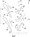
- FIG. 3 depicts a first stage of turbine rotor blades 106A of the first plurality of turbine rotor blades 106 and a first stage of turbine rotor blades 108A of the second plurality of turbine rotor blades 108.
- the first plurality of turbine rotor blades may be configured to rotate in a first circumferential direction C1
- the second plurality of turbine rotor blades may be configured to rotate in a second circumferential direction C2.
- each of the turbine rotor blades 106A of the first plurality of turbine rotor blades 106 include an airfoil 180
- each of the turbine rotor blades 108A of the second plurality of turbine rotor blades 108 include an airfoil 182.
- the airfoils 180 each define an exit angle 184
- similarly the airfoils 182 each define an exit angle 186.
- the exit angles 184, 186 each represent an angular relationship of a longitudinal centerline 102 (i.e., of the turbomachine within which they are installed) to an exit direction of the gases flowing from an upstream end 188 towards a downstream end 190 of the respective airfoils 180, 182.
- the exit angle 184 may be a negative angle, such as a negative acute angle
- the exit angle 186 may be a positive angle, such as a positive acute angle ("positive” and "negative” being used herein to denote a relative value of the respective exit angles 184, 186 viewed from the same perspective).
- exit angles 184, 186 of the airfoils 180, 182, respectively, a cause the first plurality of turbine rotor blades 106 and second plurality of turbine rotor blades 108 to rotate in the first and second circumferential directions C1, C2, respectively.
- the airfoils 180, 182 may each further include a suction side 192 and a pressure side 194.
- the suction side 192 of the airfoils 180 are configured as convex toward the first circumferential direction C1 and the pressure side 194 of the airfoils 180 are configured as concave toward the first circumferential direction C1.
- the suction side 192 of the airfoils 182 are configured as convex toward the second circumferential direction C2 and the pressure side 194 of the airfoils 180 are configured as concave toward the second circumferential direction C2.
- Such a configuration may further result in the first plurality of turbine rotor blades 106 and second plurality of turbine rotor blades 108 rotating in the first and second circumferential directions C1, C2, respectively.
- the turbomachine further includes a gearbox 122, a spool 124 (which in at least certain exemplary embodiments may be configured as the exemplary low pressure spool 36 described above with reference to Fig. 1 ), and a bearing assembly 162.
- the turbine section 100 additionally includes a turbine center frame 150, a turbine rear frame 152, and various support assemblies to connect and support the various rotatable components and stationary components within the turbine section 100.
- a gearbox 122 which in at least certain exemplary embodiments may be configured as the exemplary low pressure spool 36 described above with reference to Fig. 1
- the turbine section 100 additionally includes a turbine center frame 150, a turbine rear frame 152, and various support assemblies to connect and support the various rotatable components and stationary components within the turbine section 100.
- the turbine section 100 additionally includes a first support member assembly 126 having a first support member 128, a second support member assembly 132 having a second support member 134, a center frame support assembly 154 having a radially inner center frame support member 158 and a radially outer center frame support member 160, and a rear frame support assembly 156.
- the first support member 128 of the first support member assembly 126 generally extends between the first plurality of turbine rotor blades 106 and the spool 124, and more particularly, couples the radially inner end 110 of the first turbine rotor blade 106A of the first plurality of turbine rotor blades 106 to the spool 124.
- the first plurality of turbine rotor blades 106 is configured as a plurality of low-speed turbine rotor blades
- the second plurality of turbine rotor blades 108 is configured as a plurality of high-speed turbine rotor blades.
- the second support member 134 of the second support member assembly 132 is coupled to the second plurality of turbine rotor blades 108, or more particularly, is coupled to the radially inner end 118 of the first turbine rotor blade 108A of the second plurality of turbine rotor blades 108 for the embodiment depicted.
- the first support member 128 may couple to any of the other turbine rotor blades within the first plurality of turbine rotor blades 106 at a radially inner end 110 (either directly or through, e.g., a rotor - not shown), and similarly, the second support member 134 may couple to any of the other turbine rotor blades of the second plurality of turbine rotor blades 108 at a radially inner end 118 (either directly or through, e.g., a rotor - not shown).
- the bearing assembly 162 is provided to allow the various support assemblies to rotatably support one another.
- the bearing assembly 162 includes a first bearing 164, a second bearing 166, a third bearing 168, and a fourth bearing 170.
- the first bearing 164 and the second bearing 166 each rotatably support the second plurality of turbine rotor blades 108 through the second support member 134, and are each supported by the radially outer center frame support member 160 of the center frame support assembly 154.
- the third bearing 168 and the fourth bearing 170 of the bearing assembly 162 each rotatably support the spool 124, and are supported by the turbine center frame 150 and the turbine rear frame 152, respectively.
- the first bearing 164 is configured as a ball bearing and the second bearing 166, third bearing 168, and fourth bearing 170 are each configured as a roller bearings.
- the first bearing 164, second bearing 166, third bearing 168, and fourth bearing 170 may instead be configured in any other suitable manner, such as the other of a roller bearing or ball bearing, or alternatively, as a tapered roller bearing, an air bearing, etc.
- the bearing assembly 162 may have any other suitable configuration, including any other suitable placement of the bearings and number of bearings.
- the first plurality of turbine rotor blades 106 and the second plurality of turbine rotor blades 108 are rotatable with one another through the gearbox 122.
- the gearbox 122 is aligned with, or positioned aft of, a midpoint 176 of the turbine 104 for the embodiment depicted.
- the term "aligned with,” with reference to the axial direction A refers to the two components and/or positions having at least a portion of the same axial position.
- midpoint refers generally to an axial location halfway between a forward-most forward edge of a forward-most turbine rotor blade of the turbine 104 and an aft-most aft edge of an aft-most turbine rotor blade of the turbine 104.
- the midpoint 176 of the turbine 104 is an axial location halfway between a forward-most forward edge 172 of the third turbine rotor blade 108C of the second plurality of turbine rotor blades 108 and an aft-most aft edge 174 of the first turbine rotor blade 106A of the first plurality of turbine rotor blades 106.
- the gearbox 122 may be positioned at any other suitable location.
- the gearbox 122 may instead be positioned forward of the midpoint 176 of the turbine 104.
- the exemplary gearbox 122 depicted generally includes a ring gear 144, a sun gear 148, a planet gear 146 (or rather a plurality of planet gears 146), and a planet gear carrier.
- Each of the plurality of planet gears 146 are rotatably coupled to the planet gear carrier 147, as will be described in greater detail below.
- a first rotatable component of the turbomachine, a second rotatable component of the turbomachine, and a stationary component of the turbomachine are each couple to one of the ring gear 144, the sun gear 148, or the planet gears 146 such that the first rotatable component is rotatable with the second rotatable component through the gearbox 122.
- the first rotatable component is the first plurality of turbine rotor blades 106
- the second rotatable component is the second plurality of turbine rotor blades 108
- the stationary component is one of the forward turbine frame 150 or rear turbine frame 152.
- the first plurality of turbine rotor blades 106, the second plurality of turbine rotor blades 108, and one of the turbine center frame 150 or turbine rear frame 152 are each coupled to one of the ring gear 144, the sun gear 148, and the planet gears 146 (e.g., through the planet gear carrier 147) such that the first plurality of turbine rotor blades 106 is rotatable with the second plurality of turbine rotor blades 108 through the gearbox 122.
- the ring gear 144 is coupled to the first plurality of turbine rotor blades 106
- the sun gear 148 is coupled to the second plurality of turbine rotor blades 108
- the planet gears 146 are coupled to the turbine center frame 150 (through the planet gear carrier 147).
- the first support member 128 couples the first plurality of turbine rotor blades 106 to the ring gear 144 of the gearbox 122.
- the second support member 134 similarly couples the second plurality of turbine rotor blades 108, or rather the radially inner end 118 of the first turbine rotor blade 108A of the second plurality of turbine rotor blades 108, to sun gear 148 of the gearbox 122.
- the plurality of planet gears 146 and planet gear carrier 147 are coupled to the center frame support assembly 154, and more particularly, to the radially outer center frame support member 160 of the center frame support assembly 154.
- the first plurality of turbine rotor blades 106 are configured to rotate in an opposite direction than the second plurality of turbine rotor blades 108.
- the first plurality of turbine rotor blades 106 may be configured to rotate in a first circumferential direction C1 (see Fig. 3 ), while the second plurality of turbine rotor blades 108 may be configured to rotate in a second circumferential direction C2 (see Fig. 3 ), opposite the first circumferential direction C1.
- the turbine 104 may instead be configured to "co-rotate,” wherein the first plurality of turbine rotor blades 106 and the second plurality of turbine rotor blades 108 each rotate the same circumferential direction.
- first circumferential direction C1 and the second circumferential direction C2 as used and described herein are intended to denote directions relative to one another. Therefore, the first circumferential direction C1 may refer to a clockwise rotation (viewed from downstream looking upstream) and the second circumferential direction C2 may refer to a counter-clockwise rotation (viewed from downstream looking upstream). Alternatively, the first circumferential direction C1 may refer to a counter-clockwise rotation (viewed from downstream looking upstream) and the second circumferential direction C2 may refer to a clockwise rotation (viewed from downstream looking upstream).
- the turbomachine further includes an electric machine assembly 220 integrated with the gearbox 122.
- Fig. 4 provides a close-up, cross-sectional, schematic view of a portion of the exemplary gearbox 122 and electric machine assembly 220 of Fig. 2 .
- the electric machine assembly 220 generally includes a first electric machine 222, the first electric machine 222 including a first rotor 224 and a first stator 225.
- the first rotor 224 is coupled to one of the ring gear 144, the planet gear 146, or the sun gear 148 of the gearbox 122 such that the first rotor 224 rotates relative to the first stator 225 during operation of the turbomachine.
- the planet gear 146 depicted which may be a first planet gear 146A, defines a local axis 226A and is rotatably coupled to the planet gear carrier 147 such that it is rotatable about its local axis 226A.
- the first rotor 224 of the first electric machine 222 is coupled to the first planet gear 146A such that the first rotor 224 is rotatable about the local axis 226A of the first planet gear 146A with the first planet gear 146A.
- the first planet gear 146A is coupled to a first planet gear shaft 228A, the first planet gear shaft 228A extending along the local axis 226A of the first planet gear 146A.
- the first rotor 224 of the first electric machine 222 is coupled to the first planet gear shaft 228A, such that rotation of the first planet gear 146A correspondingly rotates the first rotor 224.
- the first stator 225 of the first electric machine 222 is fixed relative to the planet gear carrier 147.
- the first electric machine 222 includes a mount 230 extending from the planet gear carrier 147 to the first stator 225 to fix the first stator 225 in position.
- the first rotor 224 of the first electric machine 222 is configured to rotate relative to the first stator 225 of the first electric machine 222 during operation of the turbomachine.
- the electric machine assembly 220 including the first electric machine 222, is integrated into the gearbox 122.
- the gearbox 122 includes a first planet gear bearing assembly 232.
- the first planet gear 146A and first planet gear shaft 228A are together rotatably supported substantially completely by the first planet gear bearing assembly 232.
- the first planet gear bearing assembly 232 generally includes a first bearing 234 positioned forward of the first planet gear 146A and the first rotor 224 of the first electric machine 222 and a second bearing 236 positioned aft of the first planet gear 146A and the first rotor 224 of the first electric machine 222.
- the first bearing 234 and the second bearing 236 are, for the embodiment depicted, the only bearings of the first planet gear bearing assembly 232.
- integrating the electric machine assembly 220 into the gearbox 122 may allow for an overall reduction in size and weight of the two components, as the two components are sharing use of certain components. Additionally, coupling the first rotor 224 of the first electric machine 222 to the first planet gear 146A may result in a more efficient electric machine 222, as the relatively high rotational speeds of the first planet gear 146A may provide the first electric machine 222 with a desired rotor tip speed for efficient operation.
- the gearbox 122 includes a plurality of planet gears 146
- the electric machine assembly 220 further includes a plurality of rotors and a plurality of stators.
- Each of the plurality of rotors is coupled to one of the planet gears 146 of the plurality of planet gears 146 such that each rotor is rotatable about the local axis 226 of the respective planet gear 146 with the respective planet gear 146.
- the gearbox 122 includes four planet gears 146 and the electric machine assembly 220 includes four electric machines.
- the plurality of planet gears 146 includes the first planet gear 146A, a second planet gear 146B, a third planet gear 146C, and a fourth planet gear 146D
- the electric machine assembly 220 includes the first electric machine 222, a second electric machine 238, a third electric machine 240, and a fourth electric machine 242.
- Each of the planet gears 146A, 146B, 146C, 146D defines a respective local axis 226A, 226B, 226C, 226D and is rotatably coupled to the planet gear carrier 147 (depicted in Phantom in Fig. 5 for clarity), such that it may rotate relative to the planet gear carrier 147 about its respective local axis 226A, 226B, 226C, 226D.
- each of the electric machines 238, 240, 242 of the electric machine assembly 220 may be configured in a similar manner as the first electric machine 222 described above with reference to Fig. 4 .
- the first electric machine 222 includes the first rotor 224 coupled to the first planet gear 146A and the first stator 225 fixed to the planet gear carrier 147.
- the second electric machine 238 includes a second rotor 244 coupled to the second planet gear 146B and a second stator 246 coupled to the planet gear carrier 147;
- the third electric machine 240 includes a third rotor 248 coupled to the third planet gear 146C and a third stator 250 coupled to the planet gear carrier 147;
- the fourth electric machine 242 includes a fourth rotor 252 coupled to the fourth planet gear 146 and a fourth stator 254 coupled to the planet gear carrier 147.
- each of the planet gears 146A, 146B, 146C, 146D includes a respective planet gear shaft 228A, 228B, 228C, 228D extending along the respective local axis 226A, 226B, 226C, 226D of the respective planet gear 146A, 146B, 146C, 146D and the rotors 224, 244, 248, 252 of the respective electric machines 222, 238, 240, 242 are coupled to the respective planet gear shafts 228A, 228B, 228C, 228D.
- Fig. 6 a schematic view of the exemplary electric machine assembly 220 described above with reference to, e.g., Fig. 5 is provided.
- the electric machine assembly 220 further includes a main electric line 255
- Fig. 6 depicts schematically an electrical connection between each of the plurality of electric machines (i.e., the first electric machine 222, the second electric machine 238, the third electric machine 240, and the fourth electric machine 242) of the exemplary electric machine assembly 220 described above and to the main electric line 255.
- each of the plurality of electric machines 222, 238, 240, 242 generally includes a positive terminal 256 and a negative terminal 258.
- each of the plurality of electric machines 222, 238, 240, 242 are electrically connected in series with one another and the main electric line 255.
- the negative terminal 258 of the first electric machine 222 is electrically connected to the positive terminal 256 of the second electric machine 238, the negative terminal 258 of the second electric machine 238 is electrically connected to the positive terminal 256 of the third electric machine 240, and the negative terminal 258 of the third electric machine 240 is electrically connected to the positive terminal 256 of the fourth electric machine 242.
- the main electric line 255 includes a positive electric line 260 and a negative electric line 262.
- the negative terminal 258 of the fourth electric machine 242 is electrically connected to the negative electric line 262 of the main electric line 255 and the positive terminal 256 of the first electric machine 222 is electrically connected to the positive electric line 260 of the main electric line 255.
- inclusion of the plurality of electric machines 222, 238, 240, 242 configured in such an exemplary embodiment may allow for the electric machine assembly 220 to provide electrical power through the main electric line 255 at, e.g., a relatively high voltage.
- connecting the electric machines 222, 238, 240, 242 in series may allow for the electric machine assembly 220 to provide electrical power at a voltage approximately four times greater than a voltage of an individual one of the electric machines.
- the electrical power generated is provided to electrical power sinks across an aircraft. More specifically, transferring the electrical power at higher voltages may allow for use of smaller and lighter electrical lines (as compared to electrical lines configured to transfer the same wattage at a higher current), which may result in an overall lighter propulsion system for the aircraft.
- the plurality of electric machines 222, 238, 240, 242 may instead be electrically coupled together and with the main electric line 255 in any other suitable manner.
- Fig. 7 an alternative exemplary embodiment of the exemplary electric machine assembly 220 described above with reference to, e.g., Figs. 4 and 5 is depicted.
- the exemplary electric machine assembly 220 of Fig. 7 may be configured in substantially the same manner as exemplary electric machine assembly 220 described above with reference to Fig. 6 .
- the exemplary electric machine assembly 220 of Fig. 7 generally includes a main electric line 255 having a positive electric line 260 and a negative electric line 262.
- the plurality of electric machines 222, 238, 240, 242 are instead electrically connected in parallel with one another and with the main electric line 255.
- the positive terminals 256 of each of the plurality of electric machines 222, 238, 240, 242 are connected together and to the positive electric line 260 of the main electric line 255.
- the negative terminals 258 of each of the plurality of electric machines 222, 238, 240, 242 are connected together and to the negative electric line 262 of the main electric line 255.
- inclusion of the plurality of electric machines 222, 238, 240, 242 configured in accordance with such an exemplary embodiment may result in a more robust electric machine assembly 220 having increased redundancy. Further, such a configuration may allow for the electric machine assembly 220 to provide electrical power at a higher current than would otherwise be possible. For example, for the embodiment depicted, connecting the electric machines 222, 238, 240, 242 in parallel may allow for the electric machine assembly 220 to provide electrical power at having a current approximately four times greater than a current electrical power generated by an individual one of the electric machines.
- the plurality of electric machines 222, 238, 240, 242 may be connected together and to the main electric line 260 in any other suitable manner.
- the plurality of electric machines 222, 238, 240, 242 of the electric machine assembly 220 may be connected together using a combination of parallel and series connections.
- the electric machine assembly 220 may not include each of the plurality of electric machines 222, 238, 240, 242, and instead may only include the first electric machine 222 having the first rotor 224 coupled to, e.g., the first planet gear 146A. Accordingly, using the nomenclature "first" electric machine does not imply that there necessarily are multiple electric machines within the electric machine assembly 220.
- the gearbox 122 may include any other suitable number of planet gears 146, and further, the electric machine assembly 220 may include any other suitable number of electric machines (e.g., two, three, etc.).
- the exemplary electric machine assembly 220 includes a first electric machine 222 having a first rotor 224 coupled to a first planet gear 146A
- the electric machine assembly 220 may additionally, or alternatively, include one or more electric machines with a rotor coupled to, e.g., a sun gear 148, a ring gear 144, or a planet gear carrier 147 (e.g., when one of the sun gear 148 or ring gear 144 is coupled to a stationery member).
- a sun gear 148 e.g., a sun gear 148, a ring gear 144, or a planet gear carrier 147 (e.g., when one of the sun gear 148 or ring gear 144 is coupled to a stationery member).
- a sun gear 148 e.g., a sun gear 148, a ring gear 144
- a planet gear carrier 147 e.g., when one of the sun gear 148 or ring gear 144 is coupled to a stationery member
- FIG. 8 depicts a close-up, schematic, cross-sectional view of a gearbox 122 and an integrated electric machine assembly 220 in accordance with another example embodiment of the present disclosure.
- the exemplary gearbox 122 and electric machine assembly 220 of Fig. 8 may be configured in substantially the same manner as exemplary gearbox 122 and electric machine assembly 220 described above with reference to Fig. 4 .
- the gearbox 122 generally includes a ring gear 144, a plurality of planet gears 146 coupled to a planet gear carrier 147, and a sun gear 148.
- the ring gear 144 is coupled to a first rotatable component (which may be a first plurality of turbine rotor blades 106)
- the sun gear 148 is coupled to a second rotatable component (which may be a second plurality of turbine rotor blades 108)
- the plurality of planet gears 146 and planet gear carrier 147 are coupled to a stationary component (which may be a turbine center frame 150).
- the electric machine assembly 220 includes a first electric machine 222 integrated with the gearbox 122.
- a first rotor 224 of the first electric machine 222 is not rotatable with a first planet gear 146A, and instead, the first rotor 224 of the first electric machine 222 is coupled to and rotatable with one of the ring gear 144 or the sun gear 148. More particularly, for the embodiment of Fig. 8 , the first rotor 224 of the first electric machine 222 is coupled to and rotatable with the ring gear 144. Similar to the embodiment above, a first stator 225 the first electric machine 222 is fixed to the planet gear carrier 147, such that the first rotor 224 of the first electric machine 222 rotates relative to the first stator 225 during operation of the turbomachine.
- the first electric machine 222 may be configured as an "outrunner” electric machine (as compared to the "inrunner” configuration of the electric machines 222, 238, 240, 242 of the electric machine assembly 220 described above with rooms to, e.g., Fig. 4 ).
- an electric machine assembly 220 may be provided integrated into any other suitable gearbox 122 of a turbomachine having a first rotatable component, a second rotatable component, and a stationary component, wherein the first rotatable component, the second rotatable component and the stationary component are each coupled to one of a ring gear, a planet gear (through a planet gear carrier), or a sun gear of the gearbox such that the first rotatable component is rotatable with the second rotatable component through the gearbox.
- the turbomachine may include an electric machine assembly 220 integrated into, e.g., a power gearbox rotatably coupling a low pressure spool of the turbomachine to a fan shaft of a fan assembly of the turbomachine.
- the electric machine assembly 220 may be integrated into the power gear box 46 of the exemplary turbomachine 10 described above with reference to Fig. 1 , such that the first rotatable component is the low pressure spool 36 and the second rotatable component is the fan shaft of the fan assembly 38 of the exemplary turbo fan engine 10 described above with reference to Fig. 1 .
- the electric machine assembly 220 may be a relatively powerful electric machine assembly 220 capable of generating a relatively large amount of electrical power and/or providing a relatively large amount of mechanical power.
- the electric machine assembly 220 may be configured as an electric generator assembly (i.e., all electric machines of the electric machine assembly 220 are operating as electric generators to convert mechanical power into electrical power)
- the electric machine assembly 220 may be configured to generate between about one hundred (100) kilowatts of electrical power during operation of the turbomachine and about ten (10) megawatts of electrical power during operation of the turbomachine.
- the electric machine assembly 220 may be configured to generate at least about two hundred (200) kilowatts of electrical power, such as at least about three hundred (300) kilowatts of electrical power, such as at least about four hundred (400) kilowatts of electrical power during operation of the turbomachine.
- the electric machine assembly 220 may be configured as an electric motor assembly (i.e., all electric machines of the electric machine assembly 220 are operating to receive electrical power and convert such electrical power to mechanical power)
- the electric machine assembly 220 may be configured to provide between about one hundred and thirty (130) horsepower and about 13,000 horsepower of mechanical power to a first rotatable component of the turbomachine, a second rotatable component of the turbomachine, or both during operation.
- the electric machine assembly 220 may be configured to provide at least about two hundred and sixty (260) horsepower, such as at least about three hundred and ninety (390) horsepower, such as at least about five hundred and twenty (520) horsepower during operation.
- the electric machine, or each electric machine, of the electric machine assembly 220 described herein may be any suitable type of electric machine.
- the electric machine(s) may be alternating current ("AC") electric machine(s), direct current (“DC") electric machine(s), or some combination of the two.
- one or more of the electric machine(s) may be one or more of: an asynchronous or induction electric machine(s) (such as a wound field electric machine), synchronous electric machine(s), permanent magnet electric machine(s), brushless electric machine(s), brushed electric machine(s), etc.
- the turbomachine including the gearbox 122 having the electric machine assembly 220 integrated therewith may be configured as part of a propulsion system 300.
- a propulsion system 300 For example, referring now briefly to Fig. 9 , a top, schematic view is provided of an exemplary aircraft 302 having a propulsion system 300 as may incorporate various embodiments of the present disclosure. As shown in Fig. 9 , the aircraft 302 defines a longitudinal centerline 304 that extends therethrough, a lateral direction L, a forward end 306, and an aft end 308.
- the aircraft 302 includes a fuselage 310, extending longitudinally from the forward end 306 of the aircraft 302 to the aft end 308 of the aircraft 302, a first wing 312, and a second wing 314.
- the first and second wings 312, 314 each extend laterally outward with respect to the longitudinal centerline 304.
- the first wing 312 and a portion of the fuselage 310 together define a first side 316 of the aircraft 302, and the second wing 314 and another portion of the fuselage 310 together define a second side 318 of the aircraft 302.
- the first side 316 of the aircraft 302 is configured as the port side of the aircraft 302
- the second side 318 of the aircraft 302 is configured as the starboard side of the aircraft 302.
- Each of the wings 312, 314 for the exemplary embodiment depicted includes one or more leading edge flaps 320 and one or more trailing edge flaps 322.
- the aircraft 302 further includes a vertical stabilizer 324 having a rudder flap (not shown) for yaw control, and a pair of horizontal stabilizers 326, each having an elevator flap 328 for pitch control.
- the fuselage 310 additionally includes an outer surface or skin 330.
- the exemplary aircraft 302 is provided by way of example only and that in other exemplary embodiments, the aircraft 302 may have any other suitable configuration.
- the exemplary aircraft 302 includes the propulsion system 300.
- the propulsion system includes a first propulsor 332 and a second propulsor 334.
- the first propulsor 332 may be a turbomachine having a gearbox with an electric machine assembly integrated therewith.
- the first propulsor 332 may be one or more of the exemplary turbofan engine 10 and turbomachines described above with reference to Figs. 1 through 8 , including the exemplary gearbox 80 or 122 having the electric machine assembly 220 integrated therewith.
- the first propulsor 332 may include any other suitable turbomachine having a gearbox with an electric machine assembly in accordance with any of the other embodiments of the present disclosure integrated therewith.
- the second propulsor 334 of the exemplary propulsion system 300 depicted is an electric propulsor (e.g., an electric fan having an electric motor driving a propeller/fan). More specifically, the propulsion system 300 further includes an electric bus 336 and an electric energy storage unit 338 (e.g., one or more batteries).
- the electric bus 336 electrically connects the electric propulsor to the electric machine assembly 220, and more specifically to the main electric line 255 (see, e.g., Fig. 6 ) of the electric machine assembly 220 of the first propulsor 332, and is further electrically connected to the electric energy storage unit 338.
- the electric bus 336 may selectively electrically connect the electric machine assembly 220 to the electric energy storage unit 338 and/or to the second propulsor 334 (i.e., the electric propulsor).
- the electric machine assembly 220 may be electrically connectable to one or more electrical power components, such as the electric energy storage unit 338 or the electric propulsor (i.e., the second propulsor 334), for providing electrical power to, or receiving electrical power from, such electrical power component during operation of the turbomachine and propulsion system 300.
- the electric energy storage unit 338 may be configured to receive electrical power from the electric machine assembly 220 of the turbomachine during operation of the turbomachine.
- the electric energy storage unit 338 may be configured to provide electrical power to the electric machine assembly 220 of the turbomachine during operation.
- electrical power may be provided from the electric energy storage unit 338 to the electric machine assembly 220 to supplement an amount of power of the turbomachine is generating during certain operations, such as during certain high power operations, or alternatively, may be configured to drive the turbomachine, or a fan of the turbomachine, during emergency operations.
- the electrical power component may be the electric propulsor (i.e., the second propulsor 334).
- the electric machine assembly 220 may be configured to provide electrical power to the electric propulsor (i.e., the second propulsor 334), such that the electric propulsor generates thrust for the propulsion system 300 when the electric machine assembly 220 of the turbomachine provides electrical power to the electric propulsor (i.e., the second propulsor 334).
- the propulsion system 300 may have any other suitable configuration.
- the propulsion system 300 may include a plurality of electric propulsors, with each such electric propulsors electrically coupled to the electric bus 336 (and electrically connectable to the electric machine assembly 220).
- the propulsion system 300 may include any other suitable number of gas turbine engines, such as one or more of the exemplary turbomachines discussed herein, each of which including an electric machine assembly in accordance with one or more exemplary embodiments of the present disclosure.
- the propulsion system 300 may arrange the electric propulsors and gas turbine engines in any suitable manner along, e.g., the first wing 312, the second wing 314, the aft end 308, etc.
Landscapes
- Engineering & Computer Science (AREA)
- Mechanical Engineering (AREA)
- General Engineering & Computer Science (AREA)
- Chemical & Material Sciences (AREA)
- Combustion & Propulsion (AREA)
- Power Engineering (AREA)
- Aviation & Aerospace Engineering (AREA)
- Retarders (AREA)
- Connection Of Motors, Electrical Generators, Mechanical Devices, And The Like (AREA)
- Turbine Rotor Nozzle Sealing (AREA)
Applications Claiming Priority (1)
| Application Number | Priority Date | Filing Date | Title |
|---|---|---|---|
| US15/709,535 US11008883B2 (en) | 2017-09-20 | 2017-09-20 | Turbomachine with a gearbox and integrated electric machine assembly |
Publications (2)
| Publication Number | Publication Date |
|---|---|
| EP3460219A1 true EP3460219A1 (fr) | 2019-03-27 |
| EP3460219B1 EP3460219B1 (fr) | 2020-11-18 |
Family
ID=63637750
Family Applications (1)
| Application Number | Title | Priority Date | Filing Date |
|---|---|---|---|
| EP18194838.1A Active EP3460219B1 (fr) | 2017-09-20 | 2018-09-17 | Turbomachine avec une boîte de vitesses et ensemble de machine électrique intégré |
Country Status (5)
| Country | Link |
|---|---|
| US (1) | US11008883B2 (fr) |
| EP (1) | EP3460219B1 (fr) |
| JP (1) | JP6800189B2 (fr) |
| CN (1) | CN109519279B (fr) |
| CA (1) | CA3016727C (fr) |
Cited By (11)
| Publication number | Priority date | Publication date | Assignee | Title |
|---|---|---|---|---|
| EP3643906A1 (fr) * | 2018-10-23 | 2020-04-29 | Rolls-Royce plc | Boîte de vitesses épicyclique |
| IT202000002695A1 (it) * | 2020-02-11 | 2021-08-11 | Ge Avio Srl | Gruppo trasmissione ad ingranaggi provvisto di un motore elettrico |
| EP4148263A1 (fr) * | 2021-09-08 | 2023-03-15 | Rolls-Royce plc | Moteur à turbine à gaz amélioré |
| GB2610567A (en) * | 2021-09-08 | 2023-03-15 | Rolls Royce Plc | An improved gas turbine engine |
| EP4148264A1 (fr) * | 2021-09-08 | 2023-03-15 | Rolls-Royce plc | Moteur à turbine à gaz amélioré |
| US11879413B2 (en) | 2021-09-08 | 2024-01-23 | Rolls-Royce Plc | Gas turbine engine |
| US11920540B2 (en) | 2021-09-08 | 2024-03-05 | Rolls-Royce Plc | Gas turbine engine with a defined fan axis angle between a fan tip axis and a centerline |
| US11993387B2 (en) | 2021-09-08 | 2024-05-28 | Rolls-Royce Plc | Gas turbine engine |
| US12006055B2 (en) | 2021-09-08 | 2024-06-11 | Rolls-Royce Plc | Gas turbine engine with electric machines |
| US12092030B2 (en) | 2021-09-08 | 2024-09-17 | Rolls-Royce Plc | Gas turbine engine |
| US12104530B2 (en) | 2021-09-08 | 2024-10-01 | Rolls-Royce Plc | Gas turbine engine |
Families Citing this family (23)
| Publication number | Priority date | Publication date | Assignee | Title |
|---|---|---|---|---|
| US10823001B2 (en) * | 2017-09-20 | 2020-11-03 | General Electric Company | Turbomachine with alternatingly spaced turbine rotor blades |
| US11053019B2 (en) | 2018-04-19 | 2021-07-06 | The Boeing Company | Hybrid propulsion engines for aircraft |
| US10981660B2 (en) * | 2018-04-19 | 2021-04-20 | The Boeing Company | Hybrid propulsion engines for aircraft |
| US10968825B2 (en) | 2018-04-19 | 2021-04-06 | The Boeing Company | Flow multiplier systems for aircraft |
| US11891967B2 (en) * | 2018-09-21 | 2024-02-06 | Safran Aircraft Engines | Turbofan comprising a power supply device to drive the compressor |
| US11168617B2 (en) * | 2019-01-30 | 2021-11-09 | Raytheon Technologies Corporation | Electric enhanced transmission for multi-spool load-sharing turbofan engine |
| CN110159430A (zh) * | 2019-05-30 | 2019-08-23 | 邱德泉 | 一种直压式燃气轮机 |
| FR3098547B1 (fr) * | 2019-07-08 | 2022-04-29 | Safran Aircraft Engines | Assemblage de maintien d’un train d’engrenages dans une turbomachine |
| FR3098860B1 (fr) * | 2019-07-16 | 2021-06-18 | Safran Trans Systems | Reducteur a train epicycloïdal pour une turbomachine |
| FR3107916B1 (fr) * | 2020-03-03 | 2024-10-11 | Safran | Turbomachine d’aéronef avec un compresseur hybride |
| IT202000004828A1 (it) * | 2020-03-06 | 2021-09-06 | Ge Avio Srl | Supporto rotazionale per un complesso di rotore interdigitato. |
| FR3107938B1 (fr) | 2020-03-09 | 2022-02-04 | Safran Aircraft Engines | Reducteur de vitesse equipe d’une machine electrique |
| US20220065163A1 (en) * | 2020-08-31 | 2022-03-03 | General Electric Company | Ground operations of a hybrid electric propulsion system |
| EP3968503B1 (fr) * | 2020-08-31 | 2025-02-12 | General Electric Company | Turbomachine équipée d'une machine électrique intégrée dotée d'un stator segmenté et mobile |
| US20220090512A1 (en) * | 2020-09-18 | 2022-03-24 | Ge Avio Srl | Turbomachine |
| US11512637B2 (en) * | 2020-11-12 | 2022-11-29 | General Electric Company | Turbine engine bearing arrangement |
| US11428160B2 (en) | 2020-12-31 | 2022-08-30 | General Electric Company | Gas turbine engine with interdigitated turbine and gear assembly |
| US12149154B2 (en) | 2021-07-22 | 2024-11-19 | General Electric Company | Electric machine having a hybrid insulative-conductive manifold |
| CN113775416B (zh) * | 2021-09-14 | 2024-12-13 | 西北工业大学 | 一种空水两用跨介质轴流式涡轮发动机 |
| CN116054517A (zh) * | 2021-10-26 | 2023-05-02 | 励富创瑞士控股有限公司 | 节能无刷微启动发电机 |
| US11746858B1 (en) | 2022-03-11 | 2023-09-05 | Deere & Company | Multi-power source planetary system for a machine |
| WO2023211278A1 (fr) * | 2022-04-27 | 2023-11-02 | Verdego Aero, Inc. | Turboréacteur hybride à train planétaire pour mélange d'énergie entre une sortie électrique et un ventilateur de dérivation à poussée variable |
| US12480449B2 (en) | 2022-08-22 | 2025-11-25 | General Electric Company | Propulsion system including an electric machine for starting a gas turbine engine |
Citations (5)
| Publication number | Priority date | Publication date | Assignee | Title |
|---|---|---|---|---|
| GB1097632A (en) * | 1965-11-19 | 1968-01-03 | Bristol Siddeley Engines Ltd | Gas turbine power plant |
| US4936748A (en) * | 1988-11-28 | 1990-06-26 | General Electric Company | Auxiliary power source in an unducted fan gas turbine engine |
| EP1933017A2 (fr) * | 2006-12-06 | 2008-06-18 | General Electric Company | Couplage variable de bobines de moteur de réacteur à double flux via un train d'engrenages planétaire ou différentiel ouvert avec couplage pour l'extraction de puissance et l'exploitabilité du moteur |
| EP1936238A2 (fr) * | 2006-12-22 | 2008-06-25 | General Electric Company | Couplage magnétique variable de machinerie rotative |
| EP2728140A2 (fr) * | 2012-10-31 | 2014-05-07 | Rolls-Royce Deutschland Ltd & Co KG | Ensemble compresseur booster pour turbine à gaz comprenant un engrenage |
Family Cites Families (30)
| Publication number | Priority date | Publication date | Assignee | Title |
|---|---|---|---|---|
| US3688505A (en) | 1969-10-13 | 1972-09-05 | Gen Motors Corp | Ducted fan engine |
| JPS59200598A (ja) | 1983-04-27 | 1984-11-13 | Honda Keisuke | 可変指向型振動子 |
| DE3738703A1 (de) | 1987-05-27 | 1988-12-08 | Mtu Muenchen Gmbh | Kombiniertes, umschaltbares strahltriebwerk zum antrieb von flugzeugen und raumfahrzeugen |
| US5010729A (en) | 1989-01-03 | 1991-04-30 | General Electric Company | Geared counterrotating turbine/fan propulsion system |
| JP3707072B2 (ja) | 2001-01-05 | 2005-10-19 | 石川島播磨重工業株式会社 | ガスタービン発電設備 |
| US7185496B2 (en) * | 2004-07-12 | 2007-03-06 | Honeywell International, Inc. | Synchronizing stationary clutch of compression braking with a two spool gas turbine engine |
| US8104257B2 (en) * | 2004-12-01 | 2012-01-31 | United Technologies Corporation | Tip turbine engine with multiple fan and turbine stages |
| EP1825111B1 (fr) * | 2004-12-01 | 2011-08-31 | United Technologies Corporation | Carter de compresseur à rotation inverse pour un moteur à turbine en bout |
| EP1825113B1 (fr) | 2004-12-01 | 2012-10-24 | United Technologies Corporation | Boîte de vitesses contre-rotative pour moteur à turbine en bout |
| US7832193B2 (en) | 2006-10-27 | 2010-11-16 | General Electric Company | Gas turbine engine assembly and methods of assembling same |
| GB0821684D0 (en) | 2008-11-28 | 2008-12-31 | Rolls Royce Plc | Aeroengine starter/generator arrangement |
| US8191352B2 (en) | 2008-12-19 | 2012-06-05 | General Electric Company | Geared differential speed counter-rotatable low pressure turbine |
| FR2940247B1 (fr) | 2008-12-19 | 2011-01-21 | Snecma | Systeme d'helices contrarotatives entrainees par un train epicycloidal offrant une repartition de couple equilibree entre les deux helices |
| US8661781B2 (en) | 2009-02-13 | 2014-03-04 | The Boeing Company | Counter rotating fan design and variable blade row spacing optimization for low environmental impact |
| US8375695B2 (en) | 2009-06-30 | 2013-02-19 | General Electric Company | Aircraft gas turbine engine counter-rotatable generator |
| FR2950381B1 (fr) * | 2009-09-18 | 2011-10-28 | Snecma | Turbomachine a helices non carenees contrarotatives |
| US9021778B2 (en) * | 2011-06-28 | 2015-05-05 | United Technologies Corporation | Differential gear system with carrier drive |
| US20130247539A1 (en) * | 2012-03-26 | 2013-09-26 | Richard John Hoppe | Multi-shaft power extraction from gas turbine engine |
| DE102012210242A1 (de) * | 2012-06-18 | 2013-12-19 | Robert Bosch Gmbh | Elektromotor mit Planetengetriebe |
| EP3604764B1 (fr) | 2013-03-07 | 2023-04-19 | Rolls-Royce Corporation | Moteur à turbine à gaz à arbres multiples |
| AT514396B1 (de) | 2013-05-17 | 2015-11-15 | Set Sustainable Energy Technologies Gmbh | Verfahren und Vorrichtung zum Anfahren eines Triebstranges |
| US9701395B2 (en) | 2014-01-06 | 2017-07-11 | United Technologies Corporation | Contra-rotating open rotor distributed propulsion system |
| DE102014203999A1 (de) * | 2014-03-05 | 2015-09-24 | Volkswagen Aktiengesellschaft | Elektrischer Antrieb, Verfahren zu dessen Betrieb und serieller Hybridantriebsstrang für ein Kraftfahrzeug |
| US9915164B2 (en) * | 2014-05-20 | 2018-03-13 | United Technologies Corporation | Geared turbofan with high speed generator |
| US9917490B2 (en) * | 2014-11-21 | 2018-03-13 | Hamilton Sundstrand Corporation | Tail cone generator with integral speed increasing gearbox |
| US10669946B2 (en) * | 2015-06-05 | 2020-06-02 | Raytheon Technologies Corporation | Geared architecture for a gas turbine engine |
| US10590854B2 (en) * | 2016-01-26 | 2020-03-17 | United Technologies Corporation | Geared gas turbine engine |
| US11473441B2 (en) * | 2016-09-28 | 2022-10-18 | General Electric Company | Embedded electric machine |
| US20180209350A1 (en) * | 2017-01-23 | 2018-07-26 | United Technologies Corporation | Advanced Geared Gas Turbine Engine |
| US11371379B2 (en) * | 2017-08-22 | 2022-06-28 | General Electric Company | Turbomachine with alternatingly spaced turbine rotor blades |
-
2017
- 2017-09-20 US US15/709,535 patent/US11008883B2/en active Active
-
2018
- 2018-09-06 CA CA3016727A patent/CA3016727C/fr active Active
- 2018-09-07 JP JP2018167435A patent/JP6800189B2/ja active Active
- 2018-09-17 EP EP18194838.1A patent/EP3460219B1/fr active Active
- 2018-09-19 CN CN201811092684.7A patent/CN109519279B/zh active Active
Patent Citations (5)
| Publication number | Priority date | Publication date | Assignee | Title |
|---|---|---|---|---|
| GB1097632A (en) * | 1965-11-19 | 1968-01-03 | Bristol Siddeley Engines Ltd | Gas turbine power plant |
| US4936748A (en) * | 1988-11-28 | 1990-06-26 | General Electric Company | Auxiliary power source in an unducted fan gas turbine engine |
| EP1933017A2 (fr) * | 2006-12-06 | 2008-06-18 | General Electric Company | Couplage variable de bobines de moteur de réacteur à double flux via un train d'engrenages planétaire ou différentiel ouvert avec couplage pour l'extraction de puissance et l'exploitabilité du moteur |
| EP1936238A2 (fr) * | 2006-12-22 | 2008-06-25 | General Electric Company | Couplage magnétique variable de machinerie rotative |
| EP2728140A2 (fr) * | 2012-10-31 | 2014-05-07 | Rolls-Royce Deutschland Ltd & Co KG | Ensemble compresseur booster pour turbine à gaz comprenant un engrenage |
Cited By (17)
| Publication number | Priority date | Publication date | Assignee | Title |
|---|---|---|---|---|
| EP3643906A1 (fr) * | 2018-10-23 | 2020-04-29 | Rolls-Royce plc | Boîte de vitesses épicyclique |
| US11313440B2 (en) | 2018-10-23 | 2022-04-26 | Rolls-Royce Plc | Epicyclic gearbox |
| IT202000002695A1 (it) * | 2020-02-11 | 2021-08-11 | Ge Avio Srl | Gruppo trasmissione ad ingranaggi provvisto di un motore elettrico |
| US11591971B2 (en) | 2020-02-11 | 2023-02-28 | Ge Avio S.R.L. | Hybrid transmission on propeller gearbox |
| US12116939B2 (en) | 2020-02-11 | 2024-10-15 | Ge Avio S.R.L. | Hybrid transmission on propeller gearbox |
| US11879413B2 (en) | 2021-09-08 | 2024-01-23 | Rolls-Royce Plc | Gas turbine engine |
| EP4148264A1 (fr) * | 2021-09-08 | 2023-03-15 | Rolls-Royce plc | Moteur à turbine à gaz amélioré |
| EP4148262A1 (fr) * | 2021-09-08 | 2023-03-15 | Rolls-Royce plc | Turbine à gaz amélioré |
| GB2610567A (en) * | 2021-09-08 | 2023-03-15 | Rolls Royce Plc | An improved gas turbine engine |
| US11920540B2 (en) | 2021-09-08 | 2024-03-05 | Rolls-Royce Plc | Gas turbine engine with a defined fan axis angle between a fan tip axis and a centerline |
| US11976611B2 (en) | 2021-09-08 | 2024-05-07 | Rolls-Royce Plc | Gas turbine engine |
| US11993387B2 (en) | 2021-09-08 | 2024-05-28 | Rolls-Royce Plc | Gas turbine engine |
| US12006055B2 (en) | 2021-09-08 | 2024-06-11 | Rolls-Royce Plc | Gas turbine engine with electric machines |
| US12092037B2 (en) | 2021-09-08 | 2024-09-17 | Rolls-Royce Plc | Gas turbine engine with electric machines |
| US12092030B2 (en) | 2021-09-08 | 2024-09-17 | Rolls-Royce Plc | Gas turbine engine |
| US12104530B2 (en) | 2021-09-08 | 2024-10-01 | Rolls-Royce Plc | Gas turbine engine |
| EP4148263A1 (fr) * | 2021-09-08 | 2023-03-15 | Rolls-Royce plc | Moteur à turbine à gaz amélioré |
Also Published As
| Publication number | Publication date |
|---|---|
| US20190085714A1 (en) | 2019-03-21 |
| BR102018068280A2 (pt) | 2019-05-07 |
| JP2019070384A (ja) | 2019-05-09 |
| CA3016727A1 (fr) | 2019-03-20 |
| US11008883B2 (en) | 2021-05-18 |
| CN109519279A (zh) | 2019-03-26 |
| JP6800189B2 (ja) | 2020-12-16 |
| EP3460219B1 (fr) | 2020-11-18 |
| CN109519279B (zh) | 2021-09-24 |
| CA3016727C (fr) | 2020-10-27 |
Similar Documents
| Publication | Publication Date | Title |
|---|---|---|
| EP3460219B1 (fr) | Turbomachine avec une boîte de vitesses et ensemble de machine électrique intégré | |
| CA3003834C (fr) | Systeme de propulsion destine a un aeronef | |
| CN109018380B (zh) | 用于飞行器的混合电力推进系统及操作方法 | |
| CN108928493B (zh) | 用于飞行器的推进系统及其操作方法 | |
| CN114790942B (zh) | 嵌入式电机 | |
| US12116939B2 (en) | Hybrid transmission on propeller gearbox | |
| EP3216698A1 (fr) | Système de propulsion pour aéronef | |
| EP3360783A1 (fr) | Système de propulsion pour aéronef | |
| US10823000B2 (en) | Turbomachine with alternatingly spaced turbine rotor blades | |
| US10823001B2 (en) | Turbomachine with alternatingly spaced turbine rotor blades | |
| US10781717B2 (en) | Turbomachine with alternatingly spaced turbine rotor blades | |
| US11098592B2 (en) | Turbomachine with alternatingly spaced turbine rotor blades | |
| US11739694B2 (en) | Embedded electric motor assembly | |
| US20230095723A1 (en) | Turbine engine with variable pitch fan | |
| CN115199406A (zh) | 具有嵌入式电机的三流燃气涡轮发动机 | |
| US20230184175A1 (en) | Systems and methods for aligning a gearbox of a gas turbine engine | |
| BR102018068280B1 (pt) | Turbo-máquina |
Legal Events
| Date | Code | Title | Description |
|---|---|---|---|
| PUAI | Public reference made under article 153(3) epc to a published international application that has entered the european phase |
Free format text: ORIGINAL CODE: 0009012 |
|
| STAA | Information on the status of an ep patent application or granted ep patent |
Free format text: STATUS: THE APPLICATION HAS BEEN PUBLISHED |
|
| AK | Designated contracting states |
Kind code of ref document: A1 Designated state(s): AL AT BE BG CH CY CZ DE DK EE ES FI FR GB GR HR HU IE IS IT LI LT LU LV MC MK MT NL NO PL PT RO RS SE SI SK SM TR |
|
| AX | Request for extension of the european patent |
Extension state: BA ME |
|
| STAA | Information on the status of an ep patent application or granted ep patent |
Free format text: STATUS: REQUEST FOR EXAMINATION WAS MADE |
|
| 17P | Request for examination filed |
Effective date: 20190927 |
|
| RBV | Designated contracting states (corrected) |
Designated state(s): AL AT BE BG CH CY CZ DE DK EE ES FI FR GB GR HR HU IE IS IT LI LT LU LV MC MK MT NL NO PL PT RO RS SE SI SK SM TR |
|
| GRAP | Despatch of communication of intention to grant a patent |
Free format text: ORIGINAL CODE: EPIDOSNIGR1 |
|
| STAA | Information on the status of an ep patent application or granted ep patent |
Free format text: STATUS: GRANT OF PATENT IS INTENDED |
|
| INTG | Intention to grant announced |
Effective date: 20200610 |
|
| GRAS | Grant fee paid |
Free format text: ORIGINAL CODE: EPIDOSNIGR3 |
|
| GRAA | (expected) grant |
Free format text: ORIGINAL CODE: 0009210 |
|
| STAA | Information on the status of an ep patent application or granted ep patent |
Free format text: STATUS: THE PATENT HAS BEEN GRANTED |
|
| AK | Designated contracting states |
Kind code of ref document: B1 Designated state(s): AL AT BE BG CH CY CZ DE DK EE ES FI FR GB GR HR HU IE IS IT LI LT LU LV MC MK MT NL NO PL PT RO RS SE SI SK SM TR |
|
| REG | Reference to a national code |
Ref country code: GB Ref legal event code: FG4D |
|
| REG | Reference to a national code |
Ref country code: CH Ref legal event code: EP |
|
| REG | Reference to a national code |
Ref country code: IE Ref legal event code: FG4D |
|
| REG | Reference to a national code |
Ref country code: DE Ref legal event code: R096 Ref document number: 602018009812 Country of ref document: DE |
|
| REG | Reference to a national code |
Ref country code: AT Ref legal event code: REF Ref document number: 1336031 Country of ref document: AT Kind code of ref document: T Effective date: 20201215 |
|
| REG | Reference to a national code |
Ref country code: AT Ref legal event code: MK05 Ref document number: 1336031 Country of ref document: AT Kind code of ref document: T Effective date: 20201118 |
|
| REG | Reference to a national code |
Ref country code: NL Ref legal event code: MP Effective date: 20201118 |
|
| PG25 | Lapsed in a contracting state [announced via postgrant information from national office to epo] |
Ref country code: GR Free format text: LAPSE BECAUSE OF FAILURE TO SUBMIT A TRANSLATION OF THE DESCRIPTION OR TO PAY THE FEE WITHIN THE PRESCRIBED TIME-LIMIT Effective date: 20210219 Ref country code: NO Free format text: LAPSE BECAUSE OF FAILURE TO SUBMIT A TRANSLATION OF THE DESCRIPTION OR TO PAY THE FEE WITHIN THE PRESCRIBED TIME-LIMIT Effective date: 20210218 Ref country code: FI Free format text: LAPSE BECAUSE OF FAILURE TO SUBMIT A TRANSLATION OF THE DESCRIPTION OR TO PAY THE FEE WITHIN THE PRESCRIBED TIME-LIMIT Effective date: 20201118 Ref country code: RS Free format text: LAPSE BECAUSE OF FAILURE TO SUBMIT A TRANSLATION OF THE DESCRIPTION OR TO PAY THE FEE WITHIN THE PRESCRIBED TIME-LIMIT Effective date: 20201118 Ref country code: PT Free format text: LAPSE BECAUSE OF FAILURE TO SUBMIT A TRANSLATION OF THE DESCRIPTION OR TO PAY THE FEE WITHIN THE PRESCRIBED TIME-LIMIT Effective date: 20210318 |
|
| PG25 | Lapsed in a contracting state [announced via postgrant information from national office to epo] |
Ref country code: AT Free format text: LAPSE BECAUSE OF FAILURE TO SUBMIT A TRANSLATION OF THE DESCRIPTION OR TO PAY THE FEE WITHIN THE PRESCRIBED TIME-LIMIT Effective date: 20201118 Ref country code: BG Free format text: LAPSE BECAUSE OF FAILURE TO SUBMIT A TRANSLATION OF THE DESCRIPTION OR TO PAY THE FEE WITHIN THE PRESCRIBED TIME-LIMIT Effective date: 20210218 Ref country code: IS Free format text: LAPSE BECAUSE OF FAILURE TO SUBMIT A TRANSLATION OF THE DESCRIPTION OR TO PAY THE FEE WITHIN THE PRESCRIBED TIME-LIMIT Effective date: 20210318 Ref country code: LV Free format text: LAPSE BECAUSE OF FAILURE TO SUBMIT A TRANSLATION OF THE DESCRIPTION OR TO PAY THE FEE WITHIN THE PRESCRIBED TIME-LIMIT Effective date: 20201118 Ref country code: PL Free format text: LAPSE BECAUSE OF FAILURE TO SUBMIT A TRANSLATION OF THE DESCRIPTION OR TO PAY THE FEE WITHIN THE PRESCRIBED TIME-LIMIT Effective date: 20201118 Ref country code: SE Free format text: LAPSE BECAUSE OF FAILURE TO SUBMIT A TRANSLATION OF THE DESCRIPTION OR TO PAY THE FEE WITHIN THE PRESCRIBED TIME-LIMIT Effective date: 20201118 |
|
| REG | Reference to a national code |
Ref country code: LT Ref legal event code: MG9D |
|
| PG25 | Lapsed in a contracting state [announced via postgrant information from national office to epo] |
Ref country code: HR Free format text: LAPSE BECAUSE OF FAILURE TO SUBMIT A TRANSLATION OF THE DESCRIPTION OR TO PAY THE FEE WITHIN THE PRESCRIBED TIME-LIMIT Effective date: 20201118 |
|
| PG25 | Lapsed in a contracting state [announced via postgrant information from national office to epo] |
Ref country code: SM Free format text: LAPSE BECAUSE OF FAILURE TO SUBMIT A TRANSLATION OF THE DESCRIPTION OR TO PAY THE FEE WITHIN THE PRESCRIBED TIME-LIMIT Effective date: 20201118 Ref country code: CZ Free format text: LAPSE BECAUSE OF FAILURE TO SUBMIT A TRANSLATION OF THE DESCRIPTION OR TO PAY THE FEE WITHIN THE PRESCRIBED TIME-LIMIT Effective date: 20201118 Ref country code: EE Free format text: LAPSE BECAUSE OF FAILURE TO SUBMIT A TRANSLATION OF THE DESCRIPTION OR TO PAY THE FEE WITHIN THE PRESCRIBED TIME-LIMIT Effective date: 20201118 Ref country code: RO Free format text: LAPSE BECAUSE OF FAILURE TO SUBMIT A TRANSLATION OF THE DESCRIPTION OR TO PAY THE FEE WITHIN THE PRESCRIBED TIME-LIMIT Effective date: 20201118 Ref country code: SK Free format text: LAPSE BECAUSE OF FAILURE TO SUBMIT A TRANSLATION OF THE DESCRIPTION OR TO PAY THE FEE WITHIN THE PRESCRIBED TIME-LIMIT Effective date: 20201118 Ref country code: LT Free format text: LAPSE BECAUSE OF FAILURE TO SUBMIT A TRANSLATION OF THE DESCRIPTION OR TO PAY THE FEE WITHIN THE PRESCRIBED TIME-LIMIT Effective date: 20201118 |
|
| REG | Reference to a national code |
Ref country code: DE Ref legal event code: R097 Ref document number: 602018009812 Country of ref document: DE |
|
| PG25 | Lapsed in a contracting state [announced via postgrant information from national office to epo] |
Ref country code: DK Free format text: LAPSE BECAUSE OF FAILURE TO SUBMIT A TRANSLATION OF THE DESCRIPTION OR TO PAY THE FEE WITHIN THE PRESCRIBED TIME-LIMIT Effective date: 20201118 |
|
| PLBE | No opposition filed within time limit |
Free format text: ORIGINAL CODE: 0009261 |
|
| STAA | Information on the status of an ep patent application or granted ep patent |
Free format text: STATUS: NO OPPOSITION FILED WITHIN TIME LIMIT |
|
| 26N | No opposition filed |
Effective date: 20210819 |
|
| PG25 | Lapsed in a contracting state [announced via postgrant information from national office to epo] |
Ref country code: IT Free format text: LAPSE BECAUSE OF FAILURE TO SUBMIT A TRANSLATION OF THE DESCRIPTION OR TO PAY THE FEE WITHIN THE PRESCRIBED TIME-LIMIT Effective date: 20201118 Ref country code: NL Free format text: LAPSE BECAUSE OF FAILURE TO SUBMIT A TRANSLATION OF THE DESCRIPTION OR TO PAY THE FEE WITHIN THE PRESCRIBED TIME-LIMIT Effective date: 20201118 Ref country code: AL Free format text: LAPSE BECAUSE OF FAILURE TO SUBMIT A TRANSLATION OF THE DESCRIPTION OR TO PAY THE FEE WITHIN THE PRESCRIBED TIME-LIMIT Effective date: 20201118 |
|
| PG25 | Lapsed in a contracting state [announced via postgrant information from national office to epo] |
Ref country code: SI Free format text: LAPSE BECAUSE OF FAILURE TO SUBMIT A TRANSLATION OF THE DESCRIPTION OR TO PAY THE FEE WITHIN THE PRESCRIBED TIME-LIMIT Effective date: 20201118 |
|
| PG25 | Lapsed in a contracting state [announced via postgrant information from national office to epo] |
Ref country code: ES Free format text: LAPSE BECAUSE OF FAILURE TO SUBMIT A TRANSLATION OF THE DESCRIPTION OR TO PAY THE FEE WITHIN THE PRESCRIBED TIME-LIMIT Effective date: 20201118 |
|
| REG | Reference to a national code |
Ref country code: CH Ref legal event code: PL |
|
| REG | Reference to a national code |
Ref country code: BE Ref legal event code: MM Effective date: 20210930 |
|
| PG25 | Lapsed in a contracting state [announced via postgrant information from national office to epo] |
Ref country code: IS Free format text: LAPSE BECAUSE OF FAILURE TO SUBMIT A TRANSLATION OF THE DESCRIPTION OR TO PAY THE FEE WITHIN THE PRESCRIBED TIME-LIMIT Effective date: 20210318 Ref country code: MC Free format text: LAPSE BECAUSE OF FAILURE TO SUBMIT A TRANSLATION OF THE DESCRIPTION OR TO PAY THE FEE WITHIN THE PRESCRIBED TIME-LIMIT Effective date: 20201118 |
|
| PG25 | Lapsed in a contracting state [announced via postgrant information from national office to epo] |
Ref country code: LU Free format text: LAPSE BECAUSE OF NON-PAYMENT OF DUE FEES Effective date: 20210917 Ref country code: IE Free format text: LAPSE BECAUSE OF NON-PAYMENT OF DUE FEES Effective date: 20210917 Ref country code: BE Free format text: LAPSE BECAUSE OF NON-PAYMENT OF DUE FEES Effective date: 20210930 |
|
| PG25 | Lapsed in a contracting state [announced via postgrant information from national office to epo] |
Ref country code: LI Free format text: LAPSE BECAUSE OF NON-PAYMENT OF DUE FEES Effective date: 20210930 Ref country code: CH Free format text: LAPSE BECAUSE OF NON-PAYMENT OF DUE FEES Effective date: 20210930 |
|
| P01 | Opt-out of the competence of the unified patent court (upc) registered |
Effective date: 20230414 |
|
| PG25 | Lapsed in a contracting state [announced via postgrant information from national office to epo] |
Ref country code: CY Free format text: LAPSE BECAUSE OF FAILURE TO SUBMIT A TRANSLATION OF THE DESCRIPTION OR TO PAY THE FEE WITHIN THE PRESCRIBED TIME-LIMIT Effective date: 20201118 |
|
| PG25 | Lapsed in a contracting state [announced via postgrant information from national office to epo] |
Ref country code: HU Free format text: LAPSE BECAUSE OF FAILURE TO SUBMIT A TRANSLATION OF THE DESCRIPTION OR TO PAY THE FEE WITHIN THE PRESCRIBED TIME-LIMIT; INVALID AB INITIO Effective date: 20180917 |
|
| PG25 | Lapsed in a contracting state [announced via postgrant information from national office to epo] |
Ref country code: MK Free format text: LAPSE BECAUSE OF FAILURE TO SUBMIT A TRANSLATION OF THE DESCRIPTION OR TO PAY THE FEE WITHIN THE PRESCRIBED TIME-LIMIT Effective date: 20201118 |
|
| PG25 | Lapsed in a contracting state [announced via postgrant information from national office to epo] |
Ref country code: MT Free format text: LAPSE BECAUSE OF FAILURE TO SUBMIT A TRANSLATION OF THE DESCRIPTION OR TO PAY THE FEE WITHIN THE PRESCRIBED TIME-LIMIT Effective date: 20201118 |
|
| PGFP | Annual fee paid to national office [announced via postgrant information from national office to epo] |
Ref country code: DE Payment date: 20250820 Year of fee payment: 8 |
|
| PGFP | Annual fee paid to national office [announced via postgrant information from national office to epo] |
Ref country code: GB Payment date: 20250820 Year of fee payment: 8 |
|
| PGFP | Annual fee paid to national office [announced via postgrant information from national office to epo] |
Ref country code: FR Payment date: 20250820 Year of fee payment: 8 |
|
| PG25 | Lapsed in a contracting state [announced via postgrant information from national office to epo] |
Ref country code: TR Free format text: LAPSE BECAUSE OF FAILURE TO SUBMIT A TRANSLATION OF THE DESCRIPTION OR TO PAY THE FEE WITHIN THE PRESCRIBED TIME-LIMIT Effective date: 20201118 |