EP3460232B1 - Luftgestütztes system sowie system und verfahren zur luftgestützten stromerzeugung - Google Patents
Luftgestütztes system sowie system und verfahren zur luftgestützten stromerzeugung Download PDFInfo
- Publication number
- EP3460232B1 EP3460232B1 EP17192432.7A EP17192432A EP3460232B1 EP 3460232 B1 EP3460232 B1 EP 3460232B1 EP 17192432 A EP17192432 A EP 17192432A EP 3460232 B1 EP3460232 B1 EP 3460232B1
- Authority
- EP
- European Patent Office
- Prior art keywords
- unit
- airborne
- power
- coupling
- tether
- Prior art date
- Legal status (The legal status is an assumption and is not a legal conclusion. Google has not performed a legal analysis and makes no representation as to the accuracy of the status listed.)
- Active
Links
Images









Classifications
-
- F—MECHANICAL ENGINEERING; LIGHTING; HEATING; WEAPONS; BLASTING
- F03—MACHINES OR ENGINES FOR LIQUIDS; WIND, SPRING, OR WEIGHT MOTORS; PRODUCING MECHANICAL POWER OR A REACTIVE PROPULSIVE THRUST, NOT OTHERWISE PROVIDED FOR
- F03D—WIND MOTORS
- F03D9/00—Adaptations of wind motors for special use; Combinations of wind motors with apparatus driven thereby; Wind motors specially adapted for installation in particular locations
- F03D9/30—Wind motors specially adapted for installation in particular locations
- F03D9/32—Wind motors specially adapted for installation in particular locations on moving objects, e.g. vehicles
-
- B—PERFORMING OPERATIONS; TRANSPORTING
- B64—AIRCRAFT; AVIATION; COSMONAUTICS
- B64C—AEROPLANES; HELICOPTERS
- B64C31/00—Aircraft intended to be sustained without power plant; Powered hang-glider-type aircraft; Microlight-type aircraft
- B64C31/06—Kites
-
- F—MECHANICAL ENGINEERING; LIGHTING; HEATING; WEAPONS; BLASTING
- F03—MACHINES OR ENGINES FOR LIQUIDS; WIND, SPRING, OR WEIGHT MOTORS; PRODUCING MECHANICAL POWER OR A REACTIVE PROPULSIVE THRUST, NOT OTHERWISE PROVIDED FOR
- F03D—WIND MOTORS
- F03D5/00—Other wind motors
-
- F—MECHANICAL ENGINEERING; LIGHTING; HEATING; WEAPONS; BLASTING
- F05—INDEXING SCHEMES RELATING TO ENGINES OR PUMPS IN VARIOUS SUBCLASSES OF CLASSES F01-F04
- F05B—INDEXING SCHEME RELATING TO WIND, SPRING, WEIGHT, INERTIA OR LIKE MOTORS, TO MACHINES OR ENGINES FOR LIQUIDS COVERED BY SUBCLASSES F03B, F03D AND F03G
- F05B2240/00—Components
- F05B2240/90—Mounting on supporting structures or systems
- F05B2240/92—Mounting on supporting structures or systems on an airbourne structure
- F05B2240/921—Mounting on supporting structures or systems on an airbourne structure kept aloft due to aerodynamic effects
-
- Y—GENERAL TAGGING OF NEW TECHNOLOGICAL DEVELOPMENTS; GENERAL TAGGING OF CROSS-SECTIONAL TECHNOLOGIES SPANNING OVER SEVERAL SECTIONS OF THE IPC; TECHNICAL SUBJECTS COVERED BY FORMER USPC CROSS-REFERENCE ART COLLECTIONS [XRACs] AND DIGESTS
- Y02—TECHNOLOGIES OR APPLICATIONS FOR MITIGATION OR ADAPTATION AGAINST CLIMATE CHANGE
- Y02E—REDUCTION OF GREENHOUSE GAS [GHG] EMISSIONS, RELATED TO ENERGY GENERATION, TRANSMISSION OR DISTRIBUTION
- Y02E10/00—Energy generation through renewable energy sources
- Y02E10/70—Wind energy
-
- Y—GENERAL TAGGING OF NEW TECHNOLOGICAL DEVELOPMENTS; GENERAL TAGGING OF CROSS-SECTIONAL TECHNOLOGIES SPANNING OVER SEVERAL SECTIONS OF THE IPC; TECHNICAL SUBJECTS COVERED BY FORMER USPC CROSS-REFERENCE ART COLLECTIONS [XRACs] AND DIGESTS
- Y02—TECHNOLOGIES OR APPLICATIONS FOR MITIGATION OR ADAPTATION AGAINST CLIMATE CHANGE
- Y02E—REDUCTION OF GREENHOUSE GAS [GHG] EMISSIONS, RELATED TO ENERGY GENERATION, TRANSMISSION OR DISTRIBUTION
- Y02E10/00—Energy generation through renewable energy sources
- Y02E10/70—Wind energy
- Y02E10/72—Wind turbines with rotation axis in wind direction
-
- Y—GENERAL TAGGING OF NEW TECHNOLOGICAL DEVELOPMENTS; GENERAL TAGGING OF CROSS-SECTIONAL TECHNOLOGIES SPANNING OVER SEVERAL SECTIONS OF THE IPC; TECHNICAL SUBJECTS COVERED BY FORMER USPC CROSS-REFERENCE ART COLLECTIONS [XRACs] AND DIGESTS
- Y02—TECHNOLOGIES OR APPLICATIONS FOR MITIGATION OR ADAPTATION AGAINST CLIMATE CHANGE
- Y02E—REDUCTION OF GREENHOUSE GAS [GHG] EMISSIONS, RELATED TO ENERGY GENERATION, TRANSMISSION OR DISTRIBUTION
- Y02E10/00—Energy generation through renewable energy sources
- Y02E10/70—Wind energy
- Y02E10/728—Onshore wind turbines
Definitions
- the present invention refers to an airborne system, to an airborne power generation system, and method and in particular to an airborne wind power conversion system and method which are configured in order to harvest wind power and to convert the same into electrical power.
- Harvesting and converting wind power into electrical power has become popular in recent years.
- tower-based wind power conversion systems which are formed by a tower with a top equipped rotor-driven generator unit
- airborne systems have been conceived, too.
- Such airborne systems differ from known tower-based wind power conversion systems in that the rotor-driven generator unit is carried by an aerial vehicle, i.e. on an airborne unit, which is flown through the air in order to interact with wind.
- the airborne unit is retained to a ground unit by a tether which carries the mechanical load and which is also capable of electrically coupling the aerial vehicle to the ground unit, in particular in order to transmit in a generator mode electrical power converted from wind power to the ground unit.
- a tether which carries the mechanical load and which is also capable of electrically coupling the aerial vehicle to the ground unit, in particular in order to transmit in a generator mode electrical power converted from wind power to the ground unit.
- an airborne system which comprises an airborne unit configured as an aerial vehicle, an electrical power source/sink unit configured to supply, receive and/or store electrical power, and a coupling unit for electrically coupling the electrical power source/sink unit to or within the airborne unit.
- the airborne unit comprises a plurality of motor/generator units each of which having at least one wind harvesting/propelling rotor mechanically coupled thereto.
- the coupling unit is configured in order to electrically couple the electrical power source/sink unit with motor/generator units in order to transmit electrical power between the electrical power source/sink unit and motor/generator units. Groups of motor/generator units and their assigned electrical transmission paths are electrically and/or galvanically uncoupled with respect to each other at least in the airborne unit and in the coupling unit.
- the driving system of the underlying vehicle has to be supplied with electrical power by internal means. It is therefore of particular advantage if according to a preferred embodiment of the airborne system the electrical power source/sink unit (i) is at least partly comprised by the airborne unit and/or (ii) comprises or is formed by one or a plurality of electrical power storage means and/or by one or a plurality of solar power conversion means.
- respective groups of motor/generator units, electrical power storage means and/or solar power conversion means, and their assigned electrical transmission paths are electrically and/or galvanically uncoupled with respect to each other at least in the airborne unit and in the coupling unit.
- the airborne system can be configured in order to have a coupling to the ground.
- the airborne system may be formed as an airborne power generation system.
- the airborne system as an airborne power generation system may comprise an airborne unit (i) formed as a kite, an electrically driven plane and/or an electrically driven multicopter, and (ii) configured to harvest and convert wind power into electrical power.
- a ground unit may be provided which comprises or which is formed by at least a part of the electrical power source/sink unit and which is configured to send and/or receive electrical power to and from the airborne unit, respectively.
- the coupling unit may comprise or may be formed as a coupling and tether unit for mechanically and electrically coupling the airborne unit to the ground unit and configured to transmit electrical power between the airborne unit and the ground unit.
- the airborne unit comprises a plurality of motor/generator units each of which having a wind harvesting/propelling rotor mechanically coupled thereto, wherein groups of the plural motor/generator units have assigned electrical transmission paths.
- the groups of motor/generator units and their assigned electrical transmission paths are electrically and/or galvanically uncoupled, insulated, isolated and/or separated with respect to each other at least in the airborne unit and in the coupling and tether unit, but preferably in the ground unit, too.
- the mechanical coupling between the rotors and the underlying motor/generator units may be realized in different ways.
- a given rotor may be coupled to a single assigned motor/generator unit alternatively to a plurality of motor/generator units.
- a given motor/generator unit might mechanically be coupled to a single rotor or to a plurality of rotors, instead.
- the electrical and/or galvanic uncoupling can be realized by various means.
- this may be done by providing a drivetrain for each group and assigning the drivetrain to the respective group, in particular in a decided and/or distinct manner.
- the drivetrains as such are electrically and/or galvanically uncoupled, insulated, isolated and/or separated with respect to each other at least in the airborne unit and in the coupling unit in particular in the coupling and tether unit.
- a respective group may comprise one or a plurality of motor/generator units, in particular with an even number of motor/generator units.
- each group comprises the same number of motor/generator units. This offers the opportunity to consider symmetry aspects, in particular in case that an unlikely primary fault occurs and in which case a complete group of motor/generator units can be shut-off in order to maintain balance of the airborne unit and of its flight.
- a respective group comprises a single motor/generator unit, only. Under such circumstances, each motor/generator unit is electrically and/or galvanically uncoupled from any other motor/generator unit.
- the airborne unit may comprise for each respective group an assigned power electric converter and/or an assigned set and preferably a pair of cables, in particular as a part of a respective assigned drivetrain.
- the cables - which may also be referred to as lines - may at least be provided at the coupling unit side or at the coupling and tether unit side of the respective assigned power electric converter and/or may be connected or connectable to the coupling unit, to the coupling and tether unit and in particular to respective corresponding assigned sets or pairs of cables of the coupling unit and in particular of the coupling and tether unit, i.e. with a corresponding distinct assignment.
- any cable may be referred to as general electrical transmission line or the like.
- the coupling unit and in particular the coupling and tether unit may comprise for each respective group an assigned set and preferably a pair of cables connected or connectable within or to the airborne unit and/or connected or connectable to the electrical power source/sink unit and in particular to the ground unit, in particular as a part of a respective corresponding assigned drivetrain and/or to respective corresponding assigned sets or pairs of cables of the airborne unit, the electrical power source/sink unit and of the ground unit, respectively.
- each member of the pair of cables may have assigned thereto one of a positive electrical polarity and a negative electrical polarity.
- the polarity may also change over time, thus referring to an alternating or multiphase current concept.
- the concept n-tuples of cables may be used when the number of phases of the multiphase electrical current concept is above 2.
- the coupling and tether unit may comprise a core having a circumferential surface.
- Pairs or n-tuples of cables may be aligned at the circumferential surface such that each member of the pair or n-tuple of cables having assigned thereto a given polarity of a DC system or one of the set of phases of an AC system may be aligned (i) directly adjacent to a member of a pair of cables having - at least in an operation mode - the same assigned electrical polarity or phase as well as a (ii) directly adjacent to a member of a pair of cables having - at least in an operation mode - the opposite assigned electrical polarity or another or different phase, respectively.
- the ground unit comprises for each respective group an assigned set and preferably a pair of cables connected or connectable to the coupling and tether unit, in particular as a part of a respective corresponding assigned drivetrain, at a coupling and tether unit side of the ground unit and/or to respective corresponding assigned sets or pairs of cables of the coupling and tether unit.
- the ground unit comprises for each respective group of motor/generator units, in particular as a part of a respective corresponding assigned drivetrain,
- a further requirement that may preferably be fulfilled is the operation stability of the aerial vehicle during its flight.
- a respective group comprises motor/generator units which in their entirety symmetrically contribute to the mass and/or the angular momentum distribution with respect to the center of mass of the underlying airborne unit.
- the electrical power source/sink unit and in particular the ground unit may accordingly comprise for each respective group, in particular as a part of a respective corresponding assigned drivetrain, an over-current shut-off system and in particular a fuse system which is configured in order to connect a cable of the set of cables to a reference or ground potential of the electrical power source/sink unit, of the ground unit and/or of the airborne unit, in particular in case that a current conveyed by the respective cable exceeds a threshold value Imax.
- a respective fuse system comprises for each respective group, in particular as a part of a respective corresponding assigned drivetrain, in each cable of the respective assigned set of cables a fuse unit having a first fuse or fuse element electrically connected in series in each cable of the set of cables.
- At least one of (i) a second fuse element electrically connected in series to the first fuse element and in the respective cable of the set of cables and (ii) a third fuse element in parallel to (a) a serial node which is located at a side of the electrical power source/sink unit or between the first and second fuse elements and (b) to said reference or ground potential of the electrical power source/sink unit, the ground unit and/or of the airborne unit may be provide.
- said third fuse element is in serial connection combined with a diode element, both in parallel connection to the serial node between the first and second fuse elements, in particular the diode element may be connected in reverse direction relative to the potential difference between the potential of the respective cable and the reference or ground potential under normal operation conditions.
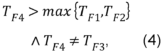
- T F6 of first to third fuses F1 to F6 of the fuse units underlying the fuse systems for the cables of the pair of cables of a given drivetrain fulfill the following conditions (1) to (6): - for the second fuse F1 of the first cable: T F 1 ⁇ T min , (1) - for the second fuse F2 of the second cable: T F 2 ⁇ T min ⁇ T F 2 ⁇ T F 1 (2) - for the first fuse F3 of the first cable: T F 3 > max ⁇ T F 1 , T F 2 ⁇ , (3) - for the first fuse F4 of the second cable: T F 4 > max ⁇ T F 1 , T F 2 ⁇ T F 4 ⁇ T F 3' (4) - for the third fuse F5 of the first cable: T F5 > max ⁇ T F 3 , T F 4 ⁇ , (5) - for the third fuse F6 of the second cable: T F 6 > max ⁇ T F 3 , T F
- a trigger or switching time of a fuse element is representative for the time interval which is necessary for the fuse element to react by separating electric and/or galvanic connection.
- the trigger and/or switching time may be defined in connection with a maximum current Imax wherein the fuse element triggers the electric and/or galvanic separation after an actual current has exceeded the maximum current Imax for a time span which corresponds to the value of the trigger or switching time.
- a trigger and/or switching time T may be defined in connection with a thermal threshold given by the absorbed power I 2 T within the melting fuse initiating the melting of and thereby the separation by the melting fuse.
- an airborne power generation method wherein an aerial vehicle as an airborne unit and having power conversion means for converting wind power to electrical power is launched, controllably flown into a wind power harvesting trajectory and then operated in order to harvest and to convert wind power into electrical power, electrical power is transmitted to or from the aerial vehicle via a coupling and tether unit, and groups of motor/generator units and their assigned electrical transmission paths are operated in an electrically and/or galvanically uncoupled manner with respect to each other at least in the airborne unit and in the coupling and tether unit and preferably also in a ground unit.
- the airborne power generation method uses an airborne power generation system according to the present invention in order to carry out wind power harvesting and conversion.
- a method of using an airborne system wherein an aerial vehicle as an airborne unit is launched and controllably flown by providing electrical power to a plurality of motor/generator units each of which having at least one propelling rotor mechanically coupled thereto for driving the same, said electrical power is transmitted within the aerial vehicle via a coupling unit, and groups of motor/generator units and their assigned electrical transmission paths are operated in an electrically and/or galvanically uncoupled manner with respect to each other at least in the airborne unit and in the coupling unit.
- an airborne system according to the present invention is used.
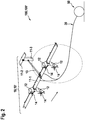
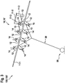
- Figures 1 to 3 schematically describe embodiments of the airborne power generation system 100 according to the present invention based on different types of underlying airborne units 10 in the form of aerial vehicles 10' formed as kites 10'.
- Each of the airborne power generation systems 100 shown in figures 1 to 3 comprises an airborne unit 10 as such, in particular in the form of an aerial vehicle 10', for instance a kite 10', a ground unit 50 which is also referred to as a ground station, and a tether and coupling unit 30 configured to carry the mechanical load as well as for transmitting electrical power between the airborne unit 10 and the ground unit 50.
- an airborne unit 10 as such, in particular in the form of an aerial vehicle 10', for instance a kite 10', a ground unit 50 which is also referred to as a ground station, and a tether and coupling unit 30 configured to carry the mechanical load as well as for transmitting electrical power between the airborne unit 10 and the ground unit 50.
- the airborne unit 10 may be formed as an aerial vehicle 10' and in particular as a kite 10'.
- the kite 10' is formed by a frame 13 having a front region with a main wing 11-1 and auxiliary wings 11-2 and 11-3 at an opposite or rear region.
- the main wing 11-1 is equipped with plural motor/generator units 12 to which mechanically coupled rotors 14 are assembled.
- the tether and coupling unit 30 is used to provide electrical power in the direction 102' from the ground station 50 to the kite 10' in order to operate and use the motor/generator units 12 on the kite 10' as motors thereby using the rotors 14 as propellers in order to controllably fly the kite 10', for instance during launching and landing.
- the kite 10' may be directed to a certain kind of wind harvesting trajectory 101.
- the operation mode can be switched from the motor mode to the generator mode upon which the rotors are driven to rotation by the flow 103 of the wind.
- the generator mode the rotation of the rotors 14 is used to drive the motor/generator units 12 as generators in order to thereby convert wind power into electrical power which can be transferred by the tether and coupling unit 30 in the direction 102 to the ground station 50.
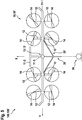
- Figure 5 gives a schematic front view of a further embodiment of the airborne power generation system 100 elucidating the arrangement of the motor/generator units 12 and of the rotors 14 in relation to the frame 13 and the center of mass 13' of the kite 10'.
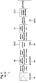
- FIG. 4 is a block diagram depicting a further embodiment of the airborne power generation system 100 according to the present invention. Here, the connection to the power grid 70 for feeding electrical power obtained by converting wind power is demonstrated.
- kite site power electronic converters 18 are useful in order to convert electrical power - which is obtained from the wind power and which may be AC power - into a suitable voltage range and polarity distribution, for instance to a DC or an AC scheme for transmission along cables 32, 33 comprised by the tether and coupling unit 30.
- power electronic converters 58 may be provided, too, in order to convert electrical power transmitted by the tether and coupling unit 30 and its electrical cables 32, 33 into a suitable voltage range and polarity scheme, for instance into AC power suitable to be fed into a power grid 70 or to be stored in an energy storage means (not shown).
- Figure 6 is a cross-sectional view representing a coupling and tether unit 30 that may be involved in an embodiment of the airborne power generation system 100 according to the present invention.
- the innermost portion of the tether and coupling unit 30 is formed by a core 31 which serves as the main mechanical load carrier.
- a core 31 which serves as the main mechanical load carrier.
- first and second cables 32 and 33 are aligned in the z direction also indicated in the frame of reference xyz shown in figure 6 .
- Each of the cables 32 and 33 extends essentially along the z direction, too, and comprises as an innermost portion a litz wire 34, 35 for transmitting electrical power along the cables 32, 33.
- the litz wire 34, 35 is surrounded by an insulator 36, followed by a shield 37 (which may be grounded to earth) and by a cable jacket 38 as the outermost portion.
- the arrangement of the core 31 having aligned on its circumferential surface 31a cables 32 and 33 is surrounded by a tether jacket 39.
- the remaining inner space 39' inside the tether jacket 39 may be filled with an appropriate filling material.
- the filling material and any other material of the tether and coupling unit's 30 components may be chosen to be flexible enough in order to allow bending and/or winding up of the tether and coupling unit 30 on a roll, a winch or the like.
- the litz wires 34 and 35 may be assigned to different polarities depending on the specific applications of the tether and coupling unit 30.
- Figure 7 is a more detailed schematic block diagram of a further embodiment of the airborne power generation system 100 according to the present invention.
- each group 16 of motor/generator units 12 comprises a single motor/generator unit 12 which is driven by wind power in the generator mode by means of the mechanically coupled rotor 14.
- each single motor/generator unit 12 drives the mechanically coupled rotor 14 as a propeller, e.g. for launching, hovering and/or landing.
- an uninterruptible power supply unit 59 which may be used in the motor mode of the airborne power generation system 100 in order to drive the rotors 14 mechanically coupled to the respective motor/generator units 12 for controllably launching, hovering and/or landing the kite 10' as an airborne unit 10.
- FIG 7 makes evident the inventive concept according to which each of the groups 16 of motor/generator units 12 is electrically and/or galvanically uncoupled from any other group 16 of motor/generator units 12. This is demonstrated by having no electric interconnection between the groups/pairs of cables 32, 33 assigned to each group 16.
- ground station 50 It is the power grid side section of the ground station 50 which is configured to join all the separated groups of cables 32, 33 assigned to the uncoupled groups 16 at respective connection nodes 57, in particular located following uninterruptible power supply units 59 of the ground station 50 at a side opposite to the coupling and tether unit 30.
- each of the drivetrains 17, 17a, 17b, ..., 17m for each group 16 is provided with an uninterruptible power supply unit 59 for realizing the motor mode controllably driving the motor/generator units 12 for controllably launching, hovering and/or landing the airborne unit 10, in particular also during a failure inside the power grid 70.
- Figure 9 shows an equivalent circuit of an embodiment of the airborne power generation system 100 according to the present invention with a particular focus on the fuse system 60 which is formed by pairs of fuse units 65 as over-current shut-off units.
- Each fuse unit 65 connects an assigned cable 32, 33 to a line carrying a ground or reference potential GND and/or a reference potential K of the underlying kite 10'. Therefore, in each cable 32, 33 the first and second fuse elements 61, 62 are connected in series. Between the first and second fuse element 61, 62 a connection node is situated. To this connection node a third fuse element 63 and a diode element 64 - which are connected in series - are connected in parallel making contact to the line carrying the reference potential K or ground potential GND.
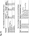
- Figure 10 gives certain operation parameters by means of parameter tables.
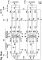
- Figure 11 shows a schematic block diagram, wherein according to a further preferred embodiment of the airborne power generation system 100 of the present invention plural motor/generator units 12 are embraced within a respective group 16 of plural motor/generator units 12.
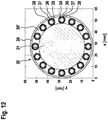
- figure 12 is a cross-sectional view representing a coupling and tether unit 30 that may be involved in an embodiment of the airborne power generation system 100 according to the present invention with a particular focus on the assignment of the polarity of potentials of directly adjacent cables 32, 33.
- Figures 13 to 19 elucidate by means of equivalent circuits and graphs showing states, currents and voltages different operation modes which are configured to handle certain operation faults in connection with airborne power generation systems 100 and methods according to the present invention.
- the present invention in particular refers to fault tolerant power electronic systems for airborne power generation systems 100 or airborne wind power conversion systems formed as drag power kites 100.
- an approach for fault tolerant power electronic systems for airborne systems 100' is disclosed.
- the key idea is to use a plurality and in particular a high number of electrical cables 32, 33 in a tether 30 underlying an airborne wind power conversion system 100, in particular a drag power kite and to leave rotor drivetrains 17 in groups electrically isolated on the kite's airborne system 100', namely in the kite 10' as such, in the tether 30 and on the ground station equipment 50.
- the power flow is parallelized behind an uninterruptible power supply of each drivetrain group 16 on the ground.
- This approach hardly affects the overall system performance e.g. due to the anyway high optimal number of electrical cables in the tether 30.
- an electrical and/or functional fault in one drivetrain group 16 does only affect the same drivetrain group 16 and a fault between two drivetrain groups 16 only affect the same two drivetrain groups 16.
- a fuse system 60 and a fault shut-off control for the power converters is proposed, with which also faults between two drivetrain groups 16 at most lead to unavailability of only one drivetrain group 16.
- open circuit faults and short circuit faults in the tether are mitigated, are overall not harmful for the system and a usual multicopter-like landing is still possible. Therefore, the proposed power electronic system design has no single point of failure.
- a generalization and a number of variants are discussed. In detail, a number of power electronic topologies and both tether power transmission types, DC and AC, are possible. In all cases any open circuit fault and any short circuit fault at most leads to unavailability of only one rotor drivetrain group 16.
- kites 10' are referred to as tethered wings and they became promising alternatives to harvest wind energy.
- kite 10' is flown in crosswind trajectories 101 like figure eights or circles.
- the considered kite 10' has onboard and thus airborne wind turbines 14 and generators 12 to generate electrical power.
- the airspeed at the kite 10' is about a magnitude higher than the actual wind speed, so that the onboard turbines 14 may be small compared to tower based turbines.
- the generators 12 and wind turbines 14 are operated as motors and as propellers, respectively, e.g. in order to perform a vertical take-off and a subsequent transition into crosswind flight.
- the reverse procedure is used for landing when the wind calms down, for maintenance or any other intermittent of generation of electric power.
- crosswind kite power or drag power
- drag power or sometimes also as “onboard-”, “continuous power generation”, “fly-gen” or “airborne wind turbine”, whereby here, this latter term is used for an onboard wind turbine of a drag power kite.
- crosswind kite power Compared to conventional wind turbines, crosswind kite power promises harvesting wind energy at higher altitudes and with stronger and steadier winds.
- the concept requires only a fraction of the construction material and costs. Hence, it promises to have lower leveled cost of electricity (LCOE).
- a drag power kite with a rated electrical power of 20 kW (“Wing 7”) has been developed by the company Makani Power/Google and it has been demonstrated autonomous power generation as well as launching and landing.
- M600 full-scale 600 kW system
- kite power plant design In general, the concept of kite power plant design is a difficult and interdisciplinary challenge. Many studies investigated the control and flight path optimization, but just a few studies investigated the design of the power electronic system. In the sense of the present invention the term "power electronic system" of a drag power kite in particular refers to all power electronics with a high power rating, and not to e.g. DC-DC converters, to supply sensors, control electronics and the like, unless otherwise stated.
- Another approach proposes an AC transmission possibly with a resonance frequency, wherein the electrical cables in the tether are connected to a transformer and a power electronic converter on the kite. The latter is further connected to an aerial DC bus to which the rotor drives are connected. On the ground, the electrical tether cables are also connected to a transformer, power electronic converters and then to the power grid.
- the comparable high capacitance of the tether and possibly additional capacitors or capacitances on the kite and/or on the ground and the inductance of the transformers and possibly additional inductors or inductances on the kite and/or on the ground may form a resonant circuit.
- the power electronic converters may generate a voltage with an AC frequency at the resonant frequency in the magnitude of a few kilohertz.
- the transformers decouple the high tether voltage from the power electronic converters with according winding numbers, the power electronic converters as well as the generators can have a low voltage rating.
- a high reliability through fault tolerance is considered as a very important design goal, such that a crash of the kite, particularly for a multi-megawatt system with a kite mass of several tons, is the maximum credible accident, which should have only a negligibly low probability of occurrence.
- batteries onboard a multi-megawatt kite which are capable to supply the rotors for a multicopter landing, are not an option, because such a high power and energy would be required for which the batteries would be too heavy.
- a hybrid solution e.g. with a gasoline engine might be too heavy and/or too complex.
- Figure 4 shows a generalized block diagram of the power electronic system 100 of a drag power kite 10' as an airborne unit 10.
- the power transmission is bi-directional.
- faults can occur, whereby only the two electrical failure modes of open circuits and short circuits are reasonable. Note that these two failure modes also cover other failure modes which lead to one of those two said failure modes: e.g. a fault in a power electronics converter 18, 58 stops that power electronics converter 18, 58 to operate which is thus like an open circuit, or e.g. an over-voltage can damage an insulation which thus can lead to a short circuit.
- the airspeed is usually high enough such that the control surfaces which are usually fault tolerant or redundant themselves can control the kite 10' alone. Therefore, a stable crosswind flight is usually also possible if one or more rotors 14 have a failure and are not available.
- the kite 10' is a tethered multicopter during hovering
- all fault tolerance measures for fault tolerant multicopters can be applied.
- the placement and rotation direction are usually chosen such that an arbitrary three-dimensional moment can be generated by differential angular speeds of the rotors 14.
- a difference to usual multicopters is that the kite 10' is tethered. Therefore, the kite 10' should always pull (slightly) on the tether 30 via a (small) pitch angle such that the tether is always under tension. Therefore, the tether 30 does not drag on the ground and tether angle sensors may be used.
- a Y-shaped bridling 30' as in figure 5 is chosen to connect the tether 30 to the kite 10', movement about the vertical axis is constrained (or more precisely, there is a restoring tether bridling moment if the yaw angle does not coincide with the azimuth angle), with which the rotor moment about the vertical axis and thus the rotor rotation directions might be irrelevant and all rotors 14 can even rotate in the same direction.
- a meaningful number of rotors 14 is six, eight or a higher even number.
- any rotor 14 has a counterpart rotor 14 which is disposed point-symmetrically with respect to the center of mass 13', as shown in figure 5 .
- This estimation also allows that any two point symmetrical rotors 14 can fail simultaneously.
- a kite dimensioning may be considered in which the excess thrust and power at least in the first mentioned rotor fault case or in these two rotor fault cases are available.
- the voltage between a positive and a negative electrical wire 32, 33 is the transmission voltage, but for a minimal insulation width the transmission voltage is "centered around ground", i.e. the voltage rating of one electrical cable is only half of the transmission voltage (plus safety margin) and the transmission voltage of an electrical cable against ground is either plus or minus half of the transmission voltage.
- the core strains and constricts. Due to the latter and the helical placement of the electrical cables 32, 33, the electrical cables 32, 33 can follow the strain like a spring with low stress.
- the tether jacket 39 is assumed to be flexible enough under strain. In-between the electrical cables 32, 33, also optical and/or conductive communication cables can be placed. Around the core 31 an additional strain-relief layer could be placed.
- the tether's aerodynamic drag is proportional to the tether's diameter but independent of the airflow direction, because the cross section of the tether 30 is round, which allows the tether 30 being easily wound on a drum.
- a model for the exact tether dimensions can be derived, e.g. based on the desired rated strength, rated voltage, rated electrical power and rated electrical transmission efficiency.
- the fault tolerant power electronic system design problem can be formulated as follows: It is an aim underlying the present invention to provide a power electronic system design (or -topology/-interconnections) in which
- R4-d the worst case in requirement is that two neighboring rotors 14 far away from the center of mass 13' fail, i.e. e.g. the two leftmost rotors 14 in figure 5 fail, by which also the two right most rotors 14 have to be turned off to balance the moments in a conservative estimation.
- a number of electrical cables 32, 33 are integrated into the tether 30, whereby a relatively high number of cables 32, 33 is meaningful such that the tether 30 has a small diameter.
- the key idea of the proposed solution is to not connect together all of the positive cables 32 to one single positive potential and all of the negative cables 33 to one single negative potential, respectively, neither on the kite nor on ground.
- one electrical cable pair is part of a single rotor drivetrain 17, 17a, 17b, ..., 17m:
- a DC transmission and parallelized power flow at the AC-grid is considered, but the concept is generalized below in the section describing plural motor/generators 12 in a group 15.
- each isolated drivetrain 17, 17a, 17b, ..., 17m consists of a rotor 14, an electrical machine 12, AC-DC converters 18 and, in case of low-voltage electrical machines, possibly DC-DC converters, to which electrical cables 32, 33 of a pair of cables of the tether 30 are connected.
- each pair of electrical cables 32, 33 is connected to its own uninterruptible power supply unit (UPS) 59 and its own ground station power electronics converter 58, before the power flow is parallelized for the injection into the AC-power grid 70.
- UPS uninterruptible power supply unit
- a block "ground station power electronic converter(s) ground” includes a potential isolation, most practical by a grid-frequency or medium-frequency transformer to obtain constant tether transmission voltages against ground. Obviously, with this approach, each rotor drivetrain is isolated (electrically insulated) from all other rotor drivetrains.
- faults inside any drivetrain 17 affect only the same drivetrain 17, e.g. a short circuit in a machine winding or in a power electronic component, and faults between any two drivetrains 17 affect only those two drivetrains 17, e.g. a short circuit between a wire of one and another rotor drivetrain 17.
- Figure 9 shows an equivalent circuit diagram of a proposed fuse system 60 with fuse units 65 and considered faults inside and between two "isolated drivetrains" 17a and 17b, where GND is the ground (earth), K is the kite's frame, I1p# and I1n# are the positive and negative current sources of the power electronic converter(s) on ground closest to the tether 30, I2# is the current source of the power converter onboard the kite closest to the tether 30, C# is a (filter) capacitor, R# is a (parasitic) resistance, F# is a fuse, D# is a diode, U# is a UPS voltage source (drawn as battery), short circuit faults are enumerated with S# and open circuit faults are enumerated with O#.
- GND is the ground (earth)
- K is the kite's frame
- I1p# and I1n# are the positive and negative current sources of the power electronic converter(s) on ground closest to the tether
- circuit diagram in figure 9 and the derived fuse system 60 in the next subsections are based on some assumptions which are highlighted and justified as follows:
- ground power electronic converter(s) 58 and the kite power electronic converter 18 closest to the tether 30 behave like controlled DC current sources in parallel to a capacitor.
- a power electronic converter 18, 58 or the combination of power electronic converter 18, 58 and machine have filter capacitors and an inductance which is a current source. Moreover the currents are controlled by a pulse width modulation (PWM) with a usually high PWM frequency. Therefore, assumption 1 can be justified.
- PWM pulse width modulation
- the UPSs 59 are the main short circuit current drivers and a short circuit current is significantly higher than the rated current of ground power electronics converters 58, tether 30 and kite power electronics converters 18.
- a UPS 59 consists of a series of connected batteries or low-voltage to high-voltage DC-DC converters (connected to a voltage source such as batteries on the low-voltage side) with according power rating.
- the DC-DC converters can keep the tether voltage, e.g. the UPS voltage, more constant, in particular apart from a short circuit and/or almost independently of the load. Those DC-DC converters must then be rated at least for the rated power needed for hovering (steady-state) and to drive a high short circuit current at least for a short time. If the DC-DC converters have enough overloading capability for a short time to drive a high enough short circuit current, they can have the same rated power as a rotor drivetrain.
- assumption 3 simplifies the fuse system design, as the fuses 61 to 63 can be selected to open at a significantly higher current than the rated current and a short circuit current is mainly driven by a UPS 59 while the grid and onboard power electronics behave like open circuits during a short circuit.
- Figure 9 visualizes the considered open (O#) and short circuit faults (S#). Note that hundreds more faults are possible, but here only representative faults are investigated, e.g. there could be also a short circuit between the cathode of a diode of a UPS and the anode of the battery of the same UPS 59, but it would have a very similar effect as short circuit S1. Note also that it is not relevant at which specific item a fault occurs, e.g. S2 could be close to the ground or close to the kite or even on the ground or onboard the kite 10'.
- O7 stands for a grid fault by which the power flow of all ground power converters 58 are stopped and all UPSs 59 step in (in motor mode).
- the (relative) fuse ratings in table 2 of figure 10 may be used, where IF# is the current through fuse F#, Imax is the maximum expected current during normal operation (including temporary overload and a safety factor, i.e. Imax is significantly higher than the rated current), TF# is the time delay of a fuse, whereby a fuse is considered to open when the "opening condition" is met over the time delay TF#, and Tmin is the minimum time delay which assures that a fuse opens only due to a short circuit current driven by UPSs (cf. assumption 3 and the discussion below), and e.g. that no fuse opens due to a start-up process (e.g. during initial charging of C2#).
- Fault S1 requires fuses F5# and F6# near the UPS voltage source. However, those fuses must be slower than all other fuses to isolate faults. E.g. S14 to S16 and S18 to S19 require fuse F1# or F2#, both faster than F5# and F6#, such that the short circuit current is stopped, but only the grid connection is separated and the UPSs can step in, i.e. the drivetrains would be still available in motor mode. Similarly, F3# or F4# must both be faster than F5# and F6# for S2 to S4, S6 to S8, S10 to S12.
- a grid power electronics converter 58 i.e. a current source I1#, is controlled as follows: During normal operation, the positive and negative voltages, respectively, are controlled to their rated values. With the simplified circuit model in figure 9 , that voltage controller can be just a P-Controller, whereby the current demanded or generated by the rotor drive onboard the kite is seen as disturbance of the voltage feedback control loop.
- the kite converter 18 is considered to be controlled as follows: In normal operation, I2# simply injects a (positive or negative) current, depending on the demands of the kite's flight and power controllers.
- the current flow of the according current source I2# is stopped, if (i) the voltage drops below a low-threshold longer than a certain time threshold, or if (ii) the voltage drops below a shut-off-threshold, or if (iii) the positive wire's and negative wire's voltage against the shield (i.e. kite frame K, or ground GND if there were no parasitics) exceed an imbalance threshold longer than a certain time threshold.
- This is to prevent further driving a short circuit current, e.g. during generator mode there would be an under-voltage in case of S4 (although that current, driven by I2a, would be limited to the rated current) and an imbalance-voltage in case of S2.
- One possibility can be to also place a fuse into the shield (geometrically between F3 and F4 in figure 9 ) and connect GND to the shields only (i.e. move the GND connection to the right of F3 and F4 in in figure 9 ).
- a drawback would be that at least one shield fuse can open in case of S2 (and other faults) and therefore the positive and negative potentials of at least one drivetrain can be floating, which can lead to high voltages of the positive and negative wires against the shield, unless further measures are considered (e.g. Ohmic balancing or a sort of active balancing with active components). Due to its complexity, such a solution is not considered here.
- a detection and repair is therefore highly desired, in particular because an additional fault could lead to a single point of failure (e.g. two undetected open circuit faults O1 in two not point-symmetrical drivetrains and then a grid fault O7).
- a possible approach to detect such faults are measurements of currents and voltages (e.g.
- the number of electrical cables must be not twice the number of rotors 14 but equal to the number of rotors 14, or multiples thereof because several cable pairs can be used for a single isolated drivetrain group as visualized in figure 11 .
- the optimal number of electrical cables can actually be used, cf. figure 8 and table 1 of figure 10 .
- With another number of rotors 14 or other dimensions for the tether 30 but two point or central symmetric rotors 14 in one drivetrain group at least a number of electrical cables closer to the optimum can be achieved.
- either one DC-DC converter for each machine can be considered or a single DC-DC converter for the two point or central symmetrical machines of same rotor drivetrain group 16 can be considered.
- ground power electronic converters 58 There is a number of possibilities for the choice of the ground power electronic converters 58, which are divided into three parts in figure 11 whereby one block could also consist only of electrical cables: E.g. in the baseline design in figure 7 , the "power electronic converter(s) ground (A)” and “(C)” are just cables, whereas “(B)” contains at least one of a DC to three-phase AC converter and a transformer.
- power electronic converter(s) ground (B) are just cables and power electronic converter(s) ground (C).
- the power flow could also be parallelized in another DC or AC voltage bus.
- power electronic converter(s) ground (B) would be a DC-DC converter (with or without isolation, i.e. e.g. with or without medium-frequency transformer) and power electronic converter(s) ground (C) would be a DC-AC converter (with isolation, i.e. e.g. with grid-frequency or medium-frequency transformer if there is no isolation in the DC-DC converter).
- UPSs 59 have a constant potential and therefore there should be an isolation in "power electronic converter(s) ground (B)" or "(C)".
- a three phase AC transmission in a similar way can also be imagined, i.e. three tether cables for each drivetrain would be used instead of two as in figure 11 .
- the machine converters or/and DC-DC converters could be placed on ground and thus only (high-voltage) machines are required on the kite.
- a three phase AC transmission comes with a number of disadvantages, and if all converters are placed on the ground the voltage frequency in the tether 30 is defined by the machine's speed.
- most sensors and the flight controllers would be placed onboard the kite whereas the controllers of important actuators would be placed on the ground, with which a highly reliable and fast real-time communication would be required. Therefore, three phase transmission approaches are not considered here.
- the electrical cables in the tether should be placed in the pattern (+-)(-+)(+-)... as depicted in figure 12 .
- the short circuits S7 and S11 are (extremely) unlikely (at least inside the tether 30, but with a reasonable routing and measures also on ground and onboard the kite) while short circuits S5 and S13 become more likely as cross drivetrain group faults, which however (likely) do not lead to unavailability of a drivetrain group as described in the section regarding the general fuse system and control approach.
- an insulating material e.g. light foam
- spacers are placed in-between the gaps of the electrical cables in figure 12 , wire-to-wire short circuits in the tether 30 are even more unlikely.
- faults should generally be made unlikely by good design, manufacturing and quality control.
- the grid fault O7 has an effect on the kite's flight control during generator mode, because in this fault all rotors 14 stop suddenly generating thrust and therefore the kite's overall drag is suddenly reduced significantly. Note that this fault can occur at any time, including when the kite 10' is diving towards the ground in a circular crosswind flight path. This can lead to a sudden acceleration of the kite which can be a challenge for the flight control system. To mitigate or eliminate that effect, brake choppers should be installed in each rotor drivetrain group 16 onboard the kite 10' (e.g. a small version for low mass) and/or on ground (e.g. a possibly bigger version due to no mass restrictions).
- the full rated power could be turned into heat on ground (for a few seconds, depending on the ratings of the brake resistors) and the flight controller can schedule a normal transition into hovering and landing.
- the UPSs step in.
- UPS 59 and (one part of the) ground converter 58 - one for the positive voltage and one for the negative voltage - are considered.
- the voltage of a UPS 59 is (implicitly) considered to be (a bit) lower than the set voltage of a ground converter 58, otherwise a UPS 59 could operate even though there is no fault. This might be an unwanted operation which is also a reason for considering diodes 64 (whereby the diodes can also be the body diodes of power electronic switches like MOSFETs or IGBTs to enable a recharging of the UPSs).
- the potentials are defined by the ground converters 58 and in a fault case, where a UPS 59 steps in, at least one potential is defined by that UPS 59.
- the kite power electronics connected to the tether 30 is considered to be not connected to the shield (or kite frame K, or ground GND), even if that part of the kite power electronics consists of a point whose potential is theoretically or in normal operation equal to the shield, like in series connected DC-DC converters or in a multilevel converter. If there is an isolation within the kite power electronics, the potential of the isolated part can be chosen freely, of course.
- a topology which behaves like a single voltage source shall be considered, a passive (Ohmic) or active centering could be also possible, but the shut-off control described in the section regarding the ground converter control has to be extended e.g. with a shut-off for voltage-imbalance. Otherwise, the potential in the tether 30 can be increased to and stay at up to three times its rated value (e.g. during S18). Moreover, further measures might be necessary, to fulfill all requirements or to limit the voltages during fault cases.
- kits without shields are thinkable.
- a similar approach as the proposed solution can be utilized to obtain a fault tolerant system, maybe only with minor adjustments to the fuse system and converter shut-off control.
- the kite frame can only be grounded high Ohmic (which might be an unacceptable risk for testing personnel) or with at least one additional ground wire in the tether 30, and the electrical cable insulation would need to be much thicker or all electrical wires would need to be embedded in materials with similar or same permittivity to sustain the electric field imposed by the voltage in the tether wires, because the electric field might then be not (almost purely) radial from the litz wire 34, 35 anymore. Therefore, also an approach with cables without shield is not considered here.
- a fuse fault is not explicitly considered in the fault analysis and in the fault tolerant system design described in the section elucidating the fuse system and control approach, because a short circuit fault and a fuse fault at the same time would be two independent faults at the same time, which is excluded by assumption 4.
- redundant fuses i.e. fuses in parallel or/and in series
- a false-open leads to one of the covered open circuit faults and a false-not-open likely leads to opening of another fuse, because most short circuit currents go at least through two fuses.
- An exception to the latter is S1, i.e. at the UPS voltage source it is meaningful to use (at least) two series connected fuses.
- adjustments to the converter shut-off control might be necessary when considering all faults together with any fuse fault.
- lead acid batteries were considered as UPS voltage-, power- and energy source. Although lead acid batteries are robust, maintenance-free and low-cost - even for a multi-megawatt system they would make only a small fraction of the total costs - also other sources are thinkable including batteries from other materials e.g. lithium, ultra-capacitors, flywheels (but must be rotating practically all the time when the kite flies, as a grid fault can happen at any time), fuel cells, gasoline or diesel generators (preferably e.g. ethanol or bio diesel from a renewable source, but also require batteries as such generators need some time to start), gas turbines (preferably with methane or hydrogen from a renewable source, but also require batteries as gas turbines need some time to start), or combinations thereof.
- batteries e.g. lithium, ultra-capacitors, flywheels (but must be rotating practically all the time when the kite flies, as a grid fault can happen at any time), fuel cells, gasoline or diesel generators (preferably e.g. ethanol or bio diesel from
- kite power electronics converters 18, ground power electronics converters 58 and of the UPSs 59 is likely an economical decision which minimizes costs and complexity.
- An interesting possibility can also be the use of different types of power electronics topologies and UPSs 59 or manufacturers thereof for the different drivetrain groups, with which a high level of versatility can be achieved and the probability of a common fault or a fault that causes several faults (e.g. programming bugs or electromagnetic interference) is decreased. Ordering equal or similar components from different manufacturers can also have economic benefits, as the dependence on one manufacturer can be reduced.
- real flight verifications and validations of new (e.g. more efficient, lighter, higher voltage) and possibly still error-prone designs are possible with low risk, if just one drivetrain group is used for the new design while reliable and tested older designs are used for the other drivetrain groups.
- the solution approach can be seen as simple - once the correct fuse and shut-off control ratings are determined - in view of figures 8a and 8b with the relatively high optimal number of electrical cables 32, 33 in the tether 30. That simplicity can be assessed as an advantage or even as ideal. Only the analysis of the faults, particularly the short circuit faults between two drivetrains, and the relative fuse ratings and thresholds for the converters' shut-off control can be tedious. Indeed, the derivation of the relative fuse ratings and the general control approach described in the section describing the fuse system and control approach was supported strongly by a large number of circuit simulations. Moreover, the choice of the exact thresholds can be tedious.
- Tref was increased from the initial value of 1 ms to 2 ms. Even this value was at the verge of achieving the acceptance criteria by viewing the relatively slow settling times of the measured currents.
- the main reason for the discrepancy of the simulated and the measured values were the poor estimations or disregard of the parasitics. Therefore, in an implementation for a real airborne system 100' or a real drag power kite plant, better models and measurements of the parasitics are beneficial, and particularly experimental verifications and validations of the choice of the thresholds are necessary.
- a further advantage of the disclosed solution is that fuses 61, 62, 63 and the control of the kite 10' and ground station converters 58 are independent, i.e. no communication or a central microcontroller are required (which themselves can be faulty). Only to schedule a landing after a fault a communication to the flight controller is required. However, the same communication busses that are needed anyways to control the kite 10', namely the communication with the rotor drive power electronics onboard the kite 10', can be used for this task.
- a grain of salt is the relatively high absolute maximum voltage in a wire U w,abs-max which occurs during some short circuit faults and requires a relatively thick insulation.
- U w,abs-max exceeds twice the rated voltage only in the short circuit faults S21-S22, and, by investigating the actual voltages of a circuit simulation, only for a very short time, until the capacitors are discharged during the short circuits. If parasitic capacitances would be considered, the over-voltage could be smaller.
- S21-S22 are faults which can be made very unlikely or even close to impossible with a reasonable ground station design and routing of the electrical cables.
- each rotor drivetrain group could contain a DC-DC converter to supply its drive control electronics, and to supply a low-voltage bus, which might or might not be isolated from the other rotor drivetrain group's low-voltage busses. Moreover, separate DC-DC converters just to supply a low-voltage bus can be used.
- a system without single point of failure might be not tolerant against extreme cases or might still have a too high (or hard to quantify) remaining risk, particularly in an early development stage. Therefore, it is also interesting to further mitigate the probability of a crash:
- the proposed solution of isolated drivetrain groups can also be used in other airborne wind energy concepts e.g. aerostats, lift power kites (i.e. kite power systems where the generator is on ground, coupled to a winch, and power is generated in a pumping process, or kite power systems pulling a load on ground such as a ship) with rotors for multicopter launch and landing or for climbing after other means than vertical launch or wind power extraction with rotors, undersea kites with rotors, or even general electric aircraft.
- aerostats i.e. kite power systems where the generator is on ground, coupled to a winch, and power is generated in a pumping process, or kite power systems pulling a load on ground such as a ship
- kite power systems pulling a load on ground such as a ship
- the "tether" 30 and (in part) the "ground station” 50 are just electrical cabling and components onboard the vehicle.
- a fuse system and a shut-off control of the power electronic converters were derived, but in detail a number of power electronic topologies for the converters and either DC or AC transmission in the tether are possible. With the generalization also a number of variants for subsystems are sketched. Moreover, further measures to design a complete kite power plant without any single point of failure, further fault tolerance enhancements, and further applications of the proposed solution are discussed.
- a circuit simulation model with an equivalent circuit of the chosen topology, tether transmission type (DC or AC), and with parasitics (measured or estimated) should be set up and all thinkable faults (at least all representative ones) at different locations (e.g. very close to the ground, middle of tether, very close to the kite), in different variants of motor and generator mode (set currents for drivetrains (a) and (b) e.g. I r , I r /2, 0, -I r /2, -I r ) should be simulated.
- the short circuit fault S2 can be estimated to have a high probability among the short circuit faults. Moreover, important ideas of the present invention become clear, by a detailed investigation.
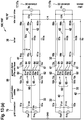
- figure 13 elucidates the investigation of short circuit fault S2: (a) short circuit currents driven by UPS(s) over different paths 41, 42 and (b) circuit after fuse opened.
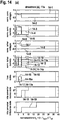
- Figure 14 reports the circuit simulation results.
- the currents in the positive wire of drivetrain (a) are high and driven by the positive UPS voltage source of drivetrain 17a, (a).
- fuse F3a opens as expected and stops the short circuit current.
- the voltage at the kite converter 18 drops below half of the voltage.
- the under-voltage and the voltage imbalance thresholds are exceeded which is why the kite converter goes into the under-voltage triggered and imbalance voltage triggered states.
- the drive still works in motor mode, supplied by the negative ground converter.
- the under-voltage time threshold is exceeded and the converter is turned off.
- All voltages are normalized for the rated voltage, all currents are normalized for the rated current of a drivetrain group 16 and the time is normalized tn for the reference time Tref and shifted to the fault time Tfault. All voltages are given with respect to the nearest shield and the sign of all currents are counted from left to right in figure 9 .
- figure 13 reports the simulation results.
- it is below the 70% rated voltage threshold such that the kite converter goes into the under-voltage triggered state.
- another rated current or other thresholds this might be not the case, but as also the imbalance threshold is exceeded, the converter will be shut off soon or later.
- figure 18a draws the short circuit current, which is driven by the positive UPS of drivetrain (a) and the negative UPS of drivetrain (b).
- the current path leads through fuse F1a and F4b, but fuse F1# opens faster than fuse F4#. Therefore, the short circuit current is stopped when F1a opens.
- figure 19 reports the simulation results.
- the kite converter voltage of drivetrain (b) drops almost to zero which forces the converter into the under-voltage state.
- the short circuit current driven by the UPSs is stopped and the voltage at the kite converter of drivetrain (b) regains the rated value which brings it back into the normal state.
- the positive ground converter continues to drive a short circuit current, which is why at the negative tether wire of drivetrain (b) on the ground conducts twice the rated current.
- the voltage at the positive grid converter is almost zero, it already went into the under-voltage trigger state.
- An actual rotor speed controller may demand a constant power, instead of a constant DC current as in the simulation.
- three further requirements for the power electronics system hardware and software design become important:
Landscapes
- Engineering & Computer Science (AREA)
- Aviation & Aerospace Engineering (AREA)
- Life Sciences & Earth Sciences (AREA)
- Sustainable Development (AREA)
- Sustainable Energy (AREA)
- Chemical & Material Sciences (AREA)
- Combustion & Propulsion (AREA)
- Mechanical Engineering (AREA)
- General Engineering & Computer Science (AREA)
- Power Engineering (AREA)
- Charge And Discharge Circuits For Batteries Or The Like (AREA)
- Control Of Eletrric Generators (AREA)
- Wind Motors (AREA)
Claims (18)
- Luftgestütztes System (100), umfassend:- eine luftgestützte Einheit (10), die als Fluggerät (10') konfiguriert ist,- eine Stromquellen-/Stromsenkeneinheit, die zum Zuführen, Aufnehmen und/oder Speichern von Strom konfiguriert ist, und- eine Verbindungseinheit zum elektrischen Verbinden der Stromquellen-/Stromsenkeneinheit an oder innerhalb der luftgestützten Einheit (10);
wobei- die luftgestützte Einheit (10) eine Vielzahl von Motor-/Generatoreinheiten (12) umfasst, von denen jede zumindest einen mechanisch damit verbundenen Windernte-/Antriebsrotor (14) umfasst,- die Verbindungseinheit zum elektrischen Verbinden der Stromquellen-/Stromsenkeneinheit mit Motor-/Generatoreinheiten (12) konfiguriert ist, um elektrischen Strom zwischen der Stromquellen-/Stromsenkeneinheit und den Motor-/Generatoreinheiten (12) zu übertragen, und- Gruppen (16) von Motor-/Generatoreinheiten (12) und deren zugeordnete elektrische Übertragungswege zumindest in der luftgestützten Einheit und in der Verbindungseinheit elektrisch und/oder galvanisch voneinander entkoppelt sind. - Luftgestütztes System (100') nach Anspruch 1, wobei die Stromquellen-/Stromsenkeneinheit- zumindest teilweise von der luftgestützten Einheit (10) gebildet ist, und/oder- eine oder eine Vielzahl von Stromspeichereinrichtungen und/oder Solarstromumwandlungseinrichtungen umfasst oder durch diese gebildet sind, wobei, insbesondere jeweilige Gruppen (16) von Motor/Generatoreinheiten (12), elektrischen Stromspeichereinrichtungen und/oder Solarstromumwandlungseinrichtungen sowie deren zugeordnete elektrische Übertragungswege, zumindest in der luftgestützten Einheit (10) und in der Verbindungseinheit, elektrisch und/oder galvanisch voneinander entkoppelt sind.
- Luftgestütztes System (100') nach Anspruch 1, das als ein luftgestütztes Stromerzeugungssystem (100) ausgebildet ist, wobei die luftgestützte Einheit (10):(i) als Drachen, elektrisch angetriebenes Flugzeug, und/oder elektrisch angetriebener Multikopter ausgebildet ist, und(ii) zum Ernten von Windkraft und zum Umwandeln in elektrischen Strom konfiguriert ist.
- Luftgestütztes System (100') nach Anspruch 3, wobei- eine Bodeneinheit (50) vorgesehen ist, die zumindest einen Teil der Stromquellen-/Stromsenkeneinheit umfasst oder durch diese gebildet ist, und die jeweils zum Senden von elektrischem Strom zur luftgestützten Einheit (10) und/oder zum Aufnehmen von dieser konfiguriert ist, und- die Verbindungseinheit als Verbindungs- und Anbindungseinheit (30) zum mechanischen und elektrischen Verbinden der luftgestützten Einheit (10) mit der Bodeneinheit (50) ausgebildet ist, und zum Übertragen von elektrischem Strom zwischen der luftgestützten Einheit (10) und der Bodeneinheit (50) konfiguriert ist.
- Luftgestütztes System (100') nach einem der vorstehenden Ansprüche, wobei- ein Antriebsstrang (17) für jede Gruppe (16) von Motor-/Generatoreinheiten (12) vorgesehen und diesen zugeordnet ist, und- die Antriebsstränge (17) zumindest in der luftgestützten Einheit (10) und in der Kupplungseinheit, insbesondere der Kupplungs- und Anbindungseinheit (30), voneinander elektrisch und/oder galvanisch entkoppelt, abgeschirmt, isoliert und/oder getrennt sind.
- Luftgestütztes System (100') nach einem der vorhergehenden Ansprüche, wobei- eine jeweilige Gruppe (16) von Motor-/Generatoreinheiten (12) eine oder eine Vielzahl von Motor-/Generatoreinheiten (12), insbesondere mit einer geraden Anzahl von Motor-/Generatoreinheiten (12) umfasst, und/oder- jede Gruppe (16) von Motor-/Generatoreinheiten (12) die gleiche Anzahl von Motor-/Generatoreinheiten (12) umfasst.
- Luftgestütztes System (100') nach einem der vorstehenden Ansprüche,
wobei die luftgestützte Einheit (10) für jede jeweilige Gruppe (16) von Motor-/Generatoreinheiten (12) einen zugeordneten Stromrichter (18) und/oder einen zugeordneten Satz, und vorzugsweise ein Paar von Kabeln (32, 33), insbesondere als Teil eines jeweils zugeordneten Antriebsstrangs (17), auf der Seite der Verbindungseinheit, und insbesondere auf der Seite der Verbindungs- und Anbindungseinheit, des jeweils zugeordneten Stromrichters (18) umfasst, und/oder mit der Verbindungseinheit, und insbesondere mit der Verbindungs- und Anbindungseinheit (30), und/oder mit jeweils entsprechend zugeordneten Sätzen oder Paaren von Kabeln (32, 33) der Verbindungseinheit und der Verbindungs- und Anbindungseinheit (30) verbunden oder verbindbar ist. - Luftgestütztes System (100') nach einem der vorhergehenden Ansprüche, wobei die Verbindungseinheit, und insbesondere die Verbindungs- und Anbindungseinheit (30), für jede jeweilige Gruppe (16) von Motor-/Generatoreinheiten (12) einen zugeordneten Satz, und vorzugsweise ein Paar von Kabeln (32, 33), umfasst, die innerhalb der oder mit der luftgestützten Einheit (10) verbunden oder verbindbar sind, und/oder mit der Stromsenken-/Stromquelleneinheit, und insbesondere mit der Bodeneinheit (50), als Teil eines jeweils entsprechend zugeordneten Antriebsstrangs (17) und/oder jeweils entsprechend zugeordneten Sätzen oder Paaren von Kabeln (32, 33) der luftgestützten Einheit (10) und der elektrischen Stromquellen-/Stromsenkeneinheit, und insbesondere der Bodeneinheit (50), verbunden oder verbindbar sind.
- Luftgestütztes System (100') nach Anspruch 8, wobei- jedem Element des Paars von Kabeln (32, 33) entweder einer positiven elektrischen Polarität und einer negativen elektrischen Polarität eines Gleichstromsystems, oder einer aus einem Satz von Phasen eines Wechselstromsystems zugeordnet ist,- die Verbindungs- und Anbindungseinheit (30) einen Kern (31) mit einer Umfangsfläche (31a) umfasst, und/oder- die Paare von Kabeln (32, 33) an der Umfangsfläche (31a) so ausgerichtet sind, dass jedes Element des Paars von Kabeln (32, 33), dem eine bestimmte Polarität oder Phase zugeordnet ist, (i) direkt angrenzend an ein Element eines Paars von Kabeln (32, 33) mit derselben zugeordneten elektrischen Polarität oder Phase, sowie (ii) direkt angrenzend an ein Element eines Paars von Kabeln (32, 33) mit der entgegengesetzten zugeordneten elektrischen Polarität oder einer unterschiedlichen Phase ausgerichtet ist.
- Luftgestütztes System (100') nach einem der vorhergehenden Ansprüche, soweit auf Anspruch 4 bezogen,
wobei die Bodeneinheit (50) für jede jeweilige Gruppe (16) einen zugeordneten Satz und vorzugsweise ein Paar von Kabeln (32, 33) umfasst, die mit der Verbindungs- und Anbindungseinheit (30), insbesondere als Teil eines jeweiligen entsprechend zugeordneten Antriebsstrangs (17), an einer Verbindungs- und Anbindungsseite der Bodeneinheit (50) und/oder mit entsprechend zugeordneten Sätzen oder Paaren von Kabeln (32, 33) der Verbindungs- und Anbindungseinheit (30) verbunden oder verbindbar sind. - Luftgestütztes System (100') nach einem der vorstehenden Ansprüche,
wobei die elektrische Stromquellen-/Stromsenkeneinheit, und insbesondere die Bodeneinheit (50), für jede jeweilige Gruppe (16), insbesondere als Teil eines jeweils entsprechend zugeordneten Antriebsstrangs (17),- eine zugeordnete unterbrechungsfreie Stromzufuhreinheit (59), insbesondere auf der Seite der Verbindungseinheit oder auf der Seite der Verbindungs- und Anbindungseinheit umfasst, und/oder zum Zuführen von Strom zum jeweils entsprechend zugeordneten Satz oder Paares von Kabeln (32, 33) zum steuerbaren Betrieb der jeweiligen Motor-/Generatoreinheiten (12) in einem Motor- oder Propellermodus, und/oder- einen zugeordneten elektronischen Stromwandler (58), der zum Aufnehmen von Strom von einem entsprechend zugeordneten Satz oder Paar von Kabeln (32, 33) zum Umwandeln des aufgenommenen Stroms, und zum Einspeisen des umgewandelten Stroms in eine Stromsenke, wie z. B. Widerstände oder ein Stromnetz (70), insbesondere gegenüber der Seite der Verbindungseinheit der Stromsenken-/Stromquelleneinheit oder der Seite der Verbindungs- und Anbindungseinheit der Bodeneinheit (50), konfiguriert ist. - Luftgestütztes System (100') nach einem der vorhergehenden Ansprüche,
wobei eine jeweilige Gruppe (16) Motor-/Generatoreinheiten (12) umfasst, die in deren Gesamtheit einen symmetrischen Beitrag in Bezug auf eine Masse und/oder einen Drehimpuls hinsichtlich des Massenschwerpunkts (13') der zugrunde liegenden Lufteinheit (10) liefern. - Luftgestütztes System (100') nach einem der vorhergehenden Ansprüche,
wobei die Stromquellen-/Stromsenkeneinheit und insbesondere die Bodeneinheit (50) für jede jeweilige Gruppe (16), insbesondere als Teil eines jeweils entsprechend zugeordneten Antriebsstrangs (17), ein Überstrom-Absperrsystem, und insbesondere ein Sicherungssystem (60), umfassen, das zum Verbinden eines Kabels (32, 33) des Satzes von Kabeln (32, 33) mit einem Referenz- oder Erdungspotential der Stromquellen-/Stromsenkeneinheit, der Bodeneinheit (50) und/oder der luftgestützten Einheit (10) für den Fall konfiguriert ist, dass ein vom jeweiligen Kabel (32, 33) übertragener Strom einen Schwellenwert (Imax) überschreitet. - Luftgestütztes System (100') nach Anspruch 13,
wobei ein jeweiliges Sicherungssystem (60) für jede jeweilige Gruppe (16), insbesondere als Teil eines jeweiligen entsprechend zugeordneten Antriebsstrangs (17), in jedem Kabel (32, 33) des jeweiligen zugeordneten Satzes von Kabeln (32, 33) eine Sicherungseinheit (65) mit einem ersten Sicherungselement (61), das in jedem Kabel (32, 33) des Satzes von Kabeln (32, 33) elektrisch in Reihe geschaltet ist, und insbesondere(i) ein zweites Sicherungselement (62), das mit dem ersten Sicherungselement (61) und in dem jeweiligen Kabel (32, 33) des Satzes von Kabeln (32, 33) elektrisch in Reihe geschaltet ist, und/oder(ii) ein drittes Sicherungselement (63) parallel zu (a) einem seriellen Knoten, der an einer Seite der elektrischen Stromquellen-/Stromsenkeneinheit oder zwischen den ersten und zweiten Sicherungselementen (61, 62) angeordnet ist, und (b) zum Referenz- oder Erdungspotenzial der Stromquellen-/Stromsenkeneinheit, der Bodeneinheit (50) und/oder der luftgestützten Einheit (10) umfasst. - Luftgestütztes System (100') nach Anspruch 14,
wobei das dritte Sicherungselement (63) in Reihenschaltung mit einem Diodenelement (64), sowie in Parallelschaltung mit dem seriellen Knoten zwischen den ersten und zweiten Sicherungselementen (61, 62), insbesondere mit dem Diodenelement (64), verbunden ist, das relativ zur normalen Potenzialdifferenz in umgekehrter Richtung zwischen dem Potenzial des jeweiligen Kabels (32, 33) und dem Bezugs- oder Erdungspotenzial angeschlossen ist. - Luftgestütztes System (100') gemäß Anspruch 14 oder 15,
wobei relative Auslöse- oder Schaltzeiten TF1, ..., TF6 von ersten bis dritten Sicherungen F1 bis F6 (61, 62, 63) der Sicherungseinheiten (65), die den Sicherungssystemen (60) für die Kabel (32, 33) des Paars von Kabeln (32, 33) eines vorgesehenen Antriebsstrangs (17) zugrunde liegen, die folgenden Bedingungen (1) bis (6) erfüllen:- für die zweite Sicherung F1 (62) des ersten Kabels (32): - für die zweite Sicherung F2 (62) des zweiten Kabels (33):
 - für die erste Sicherung F3 (61) des ersten Kabels (32):
 - für die erste Sicherung F4 (61) des zweiten Kabels (33):
 - für die dritte Sicherung F5 (63) des ersten Kabels (32):
 - für die dritte Sicherung F6 des zweiten Kabels (33):
wobei Tmin eine minimale Verzögerungszeit kennzeichnet, die zum Sicherstellen ermittelt wird, dass eine Sicherung nur aufgrund eines Kurzschlussstroms, insbesondere durch eine jeweils zugrunde liegende unterbrechungsfreie Stromversorgungseinheit (59) angetrieben, öffnet. - Luftgestütztes Stromerzeugungsverfahren, wobei- ein Fluggerät (10') als luftgestützte Einheit (10) mit einer Stromumwandlungseinrichtung zum Umwandeln von Windkraft in elektrischen Strom gestartet wird, steuerbar in eine Windkraft-Erntebahn (101) geflogen wird, und danach zum Ernten und Umwandeln von Windkraft in elektrischen Strom betrieben wird,- der elektrische Strom mittels einer Verbindungs- und Anbindungseinheit (30) zum oder vom Fluggerät (10') übertragen wird, und- Gruppen (16) von Motor-/Generatoreinheiten (12) und deren zugeordnete elektrische Übertragungswege in der luftgestützten Einheit (10) und/oder in der Verbindungs- und Anbindungseinheit (30) zueinander elektrisch und/oder galvanisch entkoppelt betrieben werden,- wobei insbesondere ein luftgestütztes System (100') als luftgestütztes Stromerzeugungssystem (100') nach einem der vorhergehenden Ansprüche, sofern direkt oder indirekt abhängig von Anspruch 4, verwendet wird.
- Verfahren zur Verwendung eines Flugsystems (100'), wobei- ein Fluggerät (10') als luftgestützte Einheit (10) gestartet und steuerbar dadurch geflogen wird, dass elektrischer Strom einer Vielzahl von Motor-/Generatoreinheiten (12) zugeführt wird, von denen jede zumindest einen mechanisch damit gekoppelten Antriebsrotor (14) zu dessen Antrieb aufweisen,- der elektrische Strom innerhalb des Fluggeräts (10') mittels einer Verbindungseinheit übertragen wird, und- Gruppen (16) von Motor-/Generatoreinheiten (12) und deren zugeordnete elektrische Übertragungswege in der luftgestützten Einheit (10) und/oder der Verbindungseinheit zueinander elektrisch und/oder galvanisch entkoppelt betrieben werden,- wobei insbesondere ein luftgestütztes System (100') nach einem der Ansprüche 1 bis 16, sofern direkt oder indirekt abhängig von Anspruch 2, verwendet wird.
Priority Applications (6)
| Application Number | Priority Date | Filing Date | Title |
|---|---|---|---|
| EP17192432.7A EP3460232B1 (de) | 2017-09-21 | 2017-09-21 | Luftgestütztes system sowie system und verfahren zur luftgestützten stromerzeugung |
| CN201880060838.6A CN111133191A (zh) | 2017-09-21 | 2018-09-14 | 机载系统和机载发电系统及方法 |
| AU2018335110A AU2018335110B2 (en) | 2017-09-21 | 2018-09-14 | Airborne system and airborne power generation system and method |
| CA3076287A CA3076287A1 (en) | 2017-09-21 | 2018-09-14 | Airborne system and airborne power generation system and method |
| PCT/EP2018/074927 WO2019057634A1 (en) | 2017-09-21 | 2018-09-14 | AIRBORNE SYSTEM AND METHOD AND SYSTEM FOR GENERATING AIRBORNE ENERGY |
| US16/648,143 US11280317B2 (en) | 2017-09-21 | 2018-09-14 | Airborne system and airborne power generation system and method |
Applications Claiming Priority (1)
| Application Number | Priority Date | Filing Date | Title |
|---|---|---|---|
| EP17192432.7A EP3460232B1 (de) | 2017-09-21 | 2017-09-21 | Luftgestütztes system sowie system und verfahren zur luftgestützten stromerzeugung |
Publications (2)
| Publication Number | Publication Date |
|---|---|
| EP3460232A1 EP3460232A1 (de) | 2019-03-27 |
| EP3460232B1 true EP3460232B1 (de) | 2020-11-25 |
Family
ID=59968974
Family Applications (1)
| Application Number | Title | Priority Date | Filing Date |
|---|---|---|---|
| EP17192432.7A Active EP3460232B1 (de) | 2017-09-21 | 2017-09-21 | Luftgestütztes system sowie system und verfahren zur luftgestützten stromerzeugung |
Country Status (6)
| Country | Link |
|---|---|
| US (1) | US11280317B2 (de) |
| EP (1) | EP3460232B1 (de) |
| CN (1) | CN111133191A (de) |
| AU (1) | AU2018335110B2 (de) |
| CA (1) | CA3076287A1 (de) |
| WO (1) | WO2019057634A1 (de) |
Families Citing this family (8)
| Publication number | Priority date | Publication date | Assignee | Title |
|---|---|---|---|---|
| IT201800007202A1 (it) * | 2018-07-13 | 2020-01-13 | Velivolo senza pilota, metodo di controllo, piattaforma associata e turbina ad alta quota | |
| IT201900009534A1 (it) * | 2019-06-19 | 2020-12-19 | E Novia S P A | Drone e metodo di controllo del suo assetto |
| CN110888324B (zh) * | 2019-12-04 | 2022-04-29 | 滨州学院 | 针对无人机舵机故障的姿态鲁棒自适应容错控制方法 |
| CN112596539B (zh) * | 2020-12-04 | 2022-08-23 | 中国航空工业集团公司成都飞机设计研究所 | 一种飞控增稳被控变量的微分提取、构造及同步方法 |
| CN112650193B (zh) * | 2020-12-04 | 2022-04-19 | 北京电子工程总体研究所 | 一种两体动力学模型试验验证方法 |
| US20230003188A1 (en) * | 2021-06-28 | 2023-01-05 | North Carolina State University | Kite-based energy generation control systems and related methods |
| CN113708679B (zh) * | 2021-08-24 | 2023-05-09 | 中国商用飞机有限责任公司 | 一种飞机起动发电系统线缆分时复用电路及方法 |
| CN121253143A (zh) * | 2025-12-05 | 2026-01-02 | 中国科学院沈阳自动化研究所 | 一种系绳收放控制试验测试装置 |
Family Cites Families (23)
| Publication number | Priority date | Publication date | Assignee | Title |
|---|---|---|---|---|
| US4285481A (en) * | 1979-06-04 | 1981-08-25 | Biscomb Lloyd I | Multiple wind turbine tethered airfoil wind energy conversion system |
| US7602077B2 (en) * | 2005-05-03 | 2009-10-13 | Magenn Power, Inc. | Systems and methods for tethered wind turbines |
| US7582981B1 (en) * | 2008-05-19 | 2009-09-01 | Moshe Meller | Airborne wind turbine electricity generating system |
| WO2010135604A2 (en) * | 2009-05-20 | 2010-11-25 | Joby Energy, Inc. | System and method for generating electrical power using a tethered airborne power generation system |
| WO2012012429A1 (en) * | 2010-07-19 | 2012-01-26 | Makani Power, Inc. | High strength windable elctromechanical tether with low fluid dynamic drag and system using same |
| US9899127B2 (en) * | 2010-07-19 | 2018-02-20 | X Development Llc | Tethers for airborne wind turbines |
| CN202645869U (zh) * | 2012-05-07 | 2013-01-02 | 郑宇航 | 一种高空漂浮式风力发电机 |
| US9611835B1 (en) * | 2013-01-11 | 2017-04-04 | Google Inc. | Motor control topology for airborne power generation and systems using same |
| WO2014146108A1 (en) * | 2013-03-15 | 2014-09-18 | Broughton Royall M Jr | High strength tether for transmitting power and communications |
| US9212032B2 (en) * | 2013-12-30 | 2015-12-15 | Google Inc. | Extruded drum surface for storage of tether |
| US9458829B2 (en) * | 2014-06-30 | 2016-10-04 | Google Inc. | Plastic optical fiber for reliable low-cost avionic networks |
| FR3025006A1 (fr) * | 2014-08-22 | 2016-02-26 | Pierre Benhaiem | Aerogenerateur a portance |
| US9664175B2 (en) * | 2014-08-30 | 2017-05-30 | X Development Llc | Carbon fiber motor rotor integrating propeller mount |
| US9771925B2 (en) * | 2014-10-13 | 2017-09-26 | X Development Llc | Tether termination systems and methods |
| EP3124379B1 (de) * | 2015-07-29 | 2019-05-01 | Airbus Defence and Space GmbH | Hybrid-elektrischer antriebsstrang für vtol drohnen |
| US9698642B1 (en) * | 2015-09-02 | 2017-07-04 | X Development Llc | Motor with multi-phase windings and series-stacked inverter |
| US20170190418A1 (en) * | 2015-12-30 | 2017-07-06 | X Development Llc | Electro-Mechanical Bridles for Energy Kites |
| US9947434B2 (en) * | 2016-01-25 | 2018-04-17 | X Development Llc | Tethers for airborne wind turbines using electrical conductor bundles |
| US9963228B2 (en) * | 2016-07-01 | 2018-05-08 | Bell Helicopter Textron Inc. | Aircraft with selectively attachable passenger pod assembly |
| WO2018067653A1 (en) * | 2016-10-05 | 2018-04-12 | X Development Llc | Methods, systems, and devices for tether core diagnostics and monitoring |
| US10288501B2 (en) * | 2016-10-05 | 2019-05-14 | Makani Technologies Llc | Torsion relieving power cable |
| US20190100305A1 (en) * | 2017-10-03 | 2019-04-04 | X Development Llc | Faired Tether Systems with Tail Span Sections |
| US10323353B2 (en) * | 2017-10-03 | 2019-06-18 | Makani Technologies Llc | Faired tether systems with internal support structure in the faired tether |
-
2017
- 2017-09-21 EP EP17192432.7A patent/EP3460232B1/de active Active
-
2018
- 2018-09-14 CN CN201880060838.6A patent/CN111133191A/zh active Pending
- 2018-09-14 US US16/648,143 patent/US11280317B2/en active Active
- 2018-09-14 WO PCT/EP2018/074927 patent/WO2019057634A1/en not_active Ceased
- 2018-09-14 AU AU2018335110A patent/AU2018335110B2/en active Active
- 2018-09-14 CA CA3076287A patent/CA3076287A1/en not_active Abandoned
Non-Patent Citations (1)
| Title |
|---|
| None * |
Also Published As
| Publication number | Publication date |
|---|---|
| EP3460232A1 (de) | 2019-03-27 |
| US11280317B2 (en) | 2022-03-22 |
| US20200256313A1 (en) | 2020-08-13 |
| AU2018335110B2 (en) | 2022-03-10 |
| CA3076287A1 (en) | 2019-03-28 |
| WO2019057634A1 (en) | 2019-03-28 |
| AU2018335110A1 (en) | 2020-04-02 |
| CN111133191A (zh) | 2020-05-08 |
Similar Documents
| Publication | Publication Date | Title |
|---|---|---|
| EP3460232B1 (de) | Luftgestütztes system sowie system und verfahren zur luftgestützten stromerzeugung | |
| Fard et al. | Aircraft distributed electric propulsion technologies—A review | |
| Ebersberger et al. | Power distribution and propulsion system for an all-electric short-range commuter aircraft—A case study | |
| CN111954622B (zh) | 具有可重构电力网络的多转子飞行器推进系统 | |
| Izquierdo et al. | Electrical power distribution system (HV270DC), for application in more electric aircraft | |
| US9567979B2 (en) | High frequency bi-directional AC power transmisssion | |
| EP3367532B1 (de) | Leistungsverwaltungs- und verteilungsarchitektur für ein raumfahrzeug | |
| CN116867661B (zh) | 具有混合电源的飞行器 | |
| US12054267B2 (en) | Hybrid propulsion architecture and aircraft containing such an architecture | |
| US11472297B2 (en) | Hybrid energy storage system | |
| US20230249563A1 (en) | Electric power supply system for vehicle | |
| US20150266588A1 (en) | Aircraft comprising a control device for a jet pipe nozzle with variable cross-section powered by two independent electrical power supplies | |
| US20210391727A1 (en) | Electrical architecture of an aircraft | |
| Lücken et al. | Design and protection of a high voltage DC onboard grid with integrated fuel cell system on more electric aircraft | |
| Bauer et al. | Fault‐Tolerant Power Electronic System for Drag Power Kites | |
| US9866152B2 (en) | Motor control topology for airborne power generation and systems using same | |
| CN118928782A (zh) | 一种航空混动推进系统及其控制方法 | |
| US9948098B1 (en) | Fault tolerance control strategies for multi-kite power generation system | |
| US9853455B1 (en) | Battery for fault handling in bidirectional power conversion systems | |
| Fletcher et al. | Modeling and simulation enabled UAV electrical power system design | |
| Hoang et al. | Designing regenerative and sustainable high endurance unmanned aerial vehicles | |
| Evale et al. | A novel design technique for electrical power system of ABT-18 unmanned aerial vehicle | |
| Rakhra | On the protection of compact DC power systems with high-power energy storage | |
| US12280881B2 (en) | Aircraft propulsion utilizing a safety critical energy management system | |
| Ibrahim et al. | Voltage synchronisation for hybrid-electric aircraft propulsion systems |
Legal Events
| Date | Code | Title | Description |
|---|---|---|---|
| PUAI | Public reference made under article 153(3) epc to a published international application that has entered the european phase |
Free format text: ORIGINAL CODE: 0009012 |
|
| STAA | Information on the status of an ep patent application or granted ep patent |
Free format text: STATUS: THE APPLICATION HAS BEEN PUBLISHED |
|
| AK | Designated contracting states |
Kind code of ref document: A1 Designated state(s): AL AT BE BG CH CY CZ DE DK EE ES FI FR GB GR HR HU IE IS IT LI LT LU LV MC MK MT NL NO PL PT RO RS SE SI SK SM TR |
|
| AX | Request for extension of the european patent |
Extension state: BA ME |
|
| STAA | Information on the status of an ep patent application or granted ep patent |
Free format text: STATUS: REQUEST FOR EXAMINATION WAS MADE |
|
| 17P | Request for examination filed |
Effective date: 20190625 |
|
| RBV | Designated contracting states (corrected) |
Designated state(s): AL AT BE BG CH CY CZ DE DK EE ES FI FR GB GR HR HU IE IS IT LI LT LU LV MC MK MT NL NO PL PT RO RS SE SI SK SM TR |
|
| GRAP | Despatch of communication of intention to grant a patent |
Free format text: ORIGINAL CODE: EPIDOSNIGR1 |
|
| STAA | Information on the status of an ep patent application or granted ep patent |
Free format text: STATUS: GRANT OF PATENT IS INTENDED |
|
| INTG | Intention to grant announced |
Effective date: 20191202 |
|
| GRAJ | Information related to disapproval of communication of intention to grant by the applicant or resumption of examination proceedings by the epo deleted |
Free format text: ORIGINAL CODE: EPIDOSDIGR1 |
|
| STAA | Information on the status of an ep patent application or granted ep patent |
Free format text: STATUS: REQUEST FOR EXAMINATION WAS MADE |
|
| INTC | Intention to grant announced (deleted) | ||
| GRAP | Despatch of communication of intention to grant a patent |
Free format text: ORIGINAL CODE: EPIDOSNIGR1 |
|
| STAA | Information on the status of an ep patent application or granted ep patent |
Free format text: STATUS: GRANT OF PATENT IS INTENDED |
|
| INTG | Intention to grant announced |
Effective date: 20200605 |
|
| GRAS | Grant fee paid |
Free format text: ORIGINAL CODE: EPIDOSNIGR3 |
|
| GRAA | (expected) grant |
Free format text: ORIGINAL CODE: 0009210 |
|
| STAA | Information on the status of an ep patent application or granted ep patent |
Free format text: STATUS: THE PATENT HAS BEEN GRANTED |
|
| AK | Designated contracting states |
Kind code of ref document: B1 Designated state(s): AL AT BE BG CH CY CZ DE DK EE ES FI FR GB GR HR HU IE IS IT LI LT LU LV MC MK MT NL NO PL PT RO RS SE SI SK SM TR |
|
| REG | Reference to a national code |
Ref country code: GB Ref legal event code: FG4D |
|
| REG | Reference to a national code |
Ref country code: CH Ref legal event code: EP |
|
| REG | Reference to a national code |
Ref country code: AT Ref legal event code: REF Ref document number: 1338619 Country of ref document: AT Kind code of ref document: T Effective date: 20201215 |
|
| REG | Reference to a national code |
Ref country code: DE Ref legal event code: R096 Ref document number: 602017028138 Country of ref document: DE |
|
| REG | Reference to a national code |
Ref country code: IE Ref legal event code: FG4D |
|
| REG | Reference to a national code |
Ref country code: AT Ref legal event code: MK05 Ref document number: 1338619 Country of ref document: AT Kind code of ref document: T Effective date: 20201125 |
|
| REG | Reference to a national code |
Ref country code: NL Ref legal event code: MP Effective date: 20201125 |
|
| PG25 | Lapsed in a contracting state [announced via postgrant information from national office to epo] |
Ref country code: GR Free format text: LAPSE BECAUSE OF FAILURE TO SUBMIT A TRANSLATION OF THE DESCRIPTION OR TO PAY THE FEE WITHIN THE PRESCRIBED TIME-LIMIT Effective date: 20210226 Ref country code: FI Free format text: LAPSE BECAUSE OF FAILURE TO SUBMIT A TRANSLATION OF THE DESCRIPTION OR TO PAY THE FEE WITHIN THE PRESCRIBED TIME-LIMIT Effective date: 20201125 Ref country code: RS Free format text: LAPSE BECAUSE OF FAILURE TO SUBMIT A TRANSLATION OF THE DESCRIPTION OR TO PAY THE FEE WITHIN THE PRESCRIBED TIME-LIMIT Effective date: 20201125 Ref country code: PT Free format text: LAPSE BECAUSE OF FAILURE TO SUBMIT A TRANSLATION OF THE DESCRIPTION OR TO PAY THE FEE WITHIN THE PRESCRIBED TIME-LIMIT Effective date: 20210325 Ref country code: NO Free format text: LAPSE BECAUSE OF FAILURE TO SUBMIT A TRANSLATION OF THE DESCRIPTION OR TO PAY THE FEE WITHIN THE PRESCRIBED TIME-LIMIT Effective date: 20210225 |
|
| PG25 | Lapsed in a contracting state [announced via postgrant information from national office to epo] |
Ref country code: AT Free format text: LAPSE BECAUSE OF FAILURE TO SUBMIT A TRANSLATION OF THE DESCRIPTION OR TO PAY THE FEE WITHIN THE PRESCRIBED TIME-LIMIT Effective date: 20201125 Ref country code: BG Free format text: LAPSE BECAUSE OF FAILURE TO SUBMIT A TRANSLATION OF THE DESCRIPTION OR TO PAY THE FEE WITHIN THE PRESCRIBED TIME-LIMIT Effective date: 20210225 Ref country code: IS Free format text: LAPSE BECAUSE OF FAILURE TO SUBMIT A TRANSLATION OF THE DESCRIPTION OR TO PAY THE FEE WITHIN THE PRESCRIBED TIME-LIMIT Effective date: 20210325 Ref country code: LV Free format text: LAPSE BECAUSE OF FAILURE TO SUBMIT A TRANSLATION OF THE DESCRIPTION OR TO PAY THE FEE WITHIN THE PRESCRIBED TIME-LIMIT Effective date: 20201125 Ref country code: PL Free format text: LAPSE BECAUSE OF FAILURE TO SUBMIT A TRANSLATION OF THE DESCRIPTION OR TO PAY THE FEE WITHIN THE PRESCRIBED TIME-LIMIT Effective date: 20201125 Ref country code: SE Free format text: LAPSE BECAUSE OF FAILURE TO SUBMIT A TRANSLATION OF THE DESCRIPTION OR TO PAY THE FEE WITHIN THE PRESCRIBED TIME-LIMIT Effective date: 20201125 |
|
| REG | Reference to a national code |
Ref country code: LT Ref legal event code: MG9D |
|
| PG25 | Lapsed in a contracting state [announced via postgrant information from national office to epo] |
Ref country code: HR Free format text: LAPSE BECAUSE OF FAILURE TO SUBMIT A TRANSLATION OF THE DESCRIPTION OR TO PAY THE FEE WITHIN THE PRESCRIBED TIME-LIMIT Effective date: 20201125 |
|
| PG25 | Lapsed in a contracting state [announced via postgrant information from national office to epo] |
Ref country code: LT Free format text: LAPSE BECAUSE OF FAILURE TO SUBMIT A TRANSLATION OF THE DESCRIPTION OR TO PAY THE FEE WITHIN THE PRESCRIBED TIME-LIMIT Effective date: 20201125 Ref country code: SM Free format text: LAPSE BECAUSE OF FAILURE TO SUBMIT A TRANSLATION OF THE DESCRIPTION OR TO PAY THE FEE WITHIN THE PRESCRIBED TIME-LIMIT Effective date: 20201125 Ref country code: EE Free format text: LAPSE BECAUSE OF FAILURE TO SUBMIT A TRANSLATION OF THE DESCRIPTION OR TO PAY THE FEE WITHIN THE PRESCRIBED TIME-LIMIT Effective date: 20201125 Ref country code: CZ Free format text: LAPSE BECAUSE OF FAILURE TO SUBMIT A TRANSLATION OF THE DESCRIPTION OR TO PAY THE FEE WITHIN THE PRESCRIBED TIME-LIMIT Effective date: 20201125 Ref country code: SK Free format text: LAPSE BECAUSE OF FAILURE TO SUBMIT A TRANSLATION OF THE DESCRIPTION OR TO PAY THE FEE WITHIN THE PRESCRIBED TIME-LIMIT Effective date: 20201125 Ref country code: RO Free format text: LAPSE BECAUSE OF FAILURE TO SUBMIT A TRANSLATION OF THE DESCRIPTION OR TO PAY THE FEE WITHIN THE PRESCRIBED TIME-LIMIT Effective date: 20201125 |
|
| REG | Reference to a national code |
Ref country code: DE Ref legal event code: R097 Ref document number: 602017028138 Country of ref document: DE |
|
| PG25 | Lapsed in a contracting state [announced via postgrant information from national office to epo] |
Ref country code: DK Free format text: LAPSE BECAUSE OF FAILURE TO SUBMIT A TRANSLATION OF THE DESCRIPTION OR TO PAY THE FEE WITHIN THE PRESCRIBED TIME-LIMIT Effective date: 20201125 |
|
| PLBE | No opposition filed within time limit |
Free format text: ORIGINAL CODE: 0009261 |
|
| STAA | Information on the status of an ep patent application or granted ep patent |
Free format text: STATUS: NO OPPOSITION FILED WITHIN TIME LIMIT |
|
| PG25 | Lapsed in a contracting state [announced via postgrant information from national office to epo] |
Ref country code: IT Free format text: LAPSE BECAUSE OF FAILURE TO SUBMIT A TRANSLATION OF THE DESCRIPTION OR TO PAY THE FEE WITHIN THE PRESCRIBED TIME-LIMIT Effective date: 20201125 Ref country code: NL Free format text: LAPSE BECAUSE OF FAILURE TO SUBMIT A TRANSLATION OF THE DESCRIPTION OR TO PAY THE FEE WITHIN THE PRESCRIBED TIME-LIMIT Effective date: 20201125 Ref country code: AL Free format text: LAPSE BECAUSE OF FAILURE TO SUBMIT A TRANSLATION OF THE DESCRIPTION OR TO PAY THE FEE WITHIN THE PRESCRIBED TIME-LIMIT Effective date: 20201125 |
|
| 26N | No opposition filed |
Effective date: 20210826 |
|
| PG25 | Lapsed in a contracting state [announced via postgrant information from national office to epo] |
Ref country code: SI Free format text: LAPSE BECAUSE OF FAILURE TO SUBMIT A TRANSLATION OF THE DESCRIPTION OR TO PAY THE FEE WITHIN THE PRESCRIBED TIME-LIMIT Effective date: 20201125 |
|
| PG25 | Lapsed in a contracting state [announced via postgrant information from national office to epo] |
Ref country code: ES Free format text: LAPSE BECAUSE OF FAILURE TO SUBMIT A TRANSLATION OF THE DESCRIPTION OR TO PAY THE FEE WITHIN THE PRESCRIBED TIME-LIMIT Effective date: 20201125 |
|
| REG | Reference to a national code |
Ref country code: CH Ref legal event code: PL |
|
| REG | Reference to a national code |
Ref country code: BE Ref legal event code: MM Effective date: 20210930 |
|
| GBPC | Gb: european patent ceased through non-payment of renewal fee |
Effective date: 20210921 |
|
| PG25 | Lapsed in a contracting state [announced via postgrant information from national office to epo] |
Ref country code: IS Free format text: LAPSE BECAUSE OF FAILURE TO SUBMIT A TRANSLATION OF THE DESCRIPTION OR TO PAY THE FEE WITHIN THE PRESCRIBED TIME-LIMIT Effective date: 20210325 Ref country code: MC Free format text: LAPSE BECAUSE OF FAILURE TO SUBMIT A TRANSLATION OF THE DESCRIPTION OR TO PAY THE FEE WITHIN THE PRESCRIBED TIME-LIMIT Effective date: 20201125 |
|
| PG25 | Lapsed in a contracting state [announced via postgrant information from national office to epo] |
Ref country code: LU Free format text: LAPSE BECAUSE OF NON-PAYMENT OF DUE FEES Effective date: 20210921 Ref country code: IE Free format text: LAPSE BECAUSE OF NON-PAYMENT OF DUE FEES Effective date: 20210921 Ref country code: GB Free format text: LAPSE BECAUSE OF NON-PAYMENT OF DUE FEES Effective date: 20210921 Ref country code: FR Free format text: LAPSE BECAUSE OF NON-PAYMENT OF DUE FEES Effective date: 20210930 Ref country code: BE Free format text: LAPSE BECAUSE OF NON-PAYMENT OF DUE FEES Effective date: 20210930 |
|
| PG25 | Lapsed in a contracting state [announced via postgrant information from national office to epo] |
Ref country code: LI Free format text: LAPSE BECAUSE OF NON-PAYMENT OF DUE FEES Effective date: 20210930 Ref country code: CH Free format text: LAPSE BECAUSE OF NON-PAYMENT OF DUE FEES Effective date: 20210930 |
|
| PG25 | Lapsed in a contracting state [announced via postgrant information from national office to epo] |
Ref country code: CY Free format text: LAPSE BECAUSE OF FAILURE TO SUBMIT A TRANSLATION OF THE DESCRIPTION OR TO PAY THE FEE WITHIN THE PRESCRIBED TIME-LIMIT Effective date: 20201125 |
|
| PG25 | Lapsed in a contracting state [announced via postgrant information from national office to epo] |
Ref country code: HU Free format text: LAPSE BECAUSE OF FAILURE TO SUBMIT A TRANSLATION OF THE DESCRIPTION OR TO PAY THE FEE WITHIN THE PRESCRIBED TIME-LIMIT; INVALID AB INITIO Effective date: 20170921 |
|
| PG25 | Lapsed in a contracting state [announced via postgrant information from national office to epo] |
Ref country code: MK Free format text: LAPSE BECAUSE OF FAILURE TO SUBMIT A TRANSLATION OF THE DESCRIPTION OR TO PAY THE FEE WITHIN THE PRESCRIBED TIME-LIMIT Effective date: 20201125 |
|
| REG | Reference to a national code |
Ref country code: DE Ref legal event code: R081 Ref document number: 602017028138 Country of ref document: DE Owner name: KITEKRAFT GMBH, DE Free format text: FORMER OWNER: TECHNISCHE UNIVERSITAET MUENCHEN, 80333 MUENCHEN, DE |
|
| PG25 | Lapsed in a contracting state [announced via postgrant information from national office to epo] |
Ref country code: TR Free format text: LAPSE BECAUSE OF FAILURE TO SUBMIT A TRANSLATION OF THE DESCRIPTION OR TO PAY THE FEE WITHIN THE PRESCRIBED TIME-LIMIT Effective date: 20201125 |
|
| PG25 | Lapsed in a contracting state [announced via postgrant information from national office to epo] |
Ref country code: MT Free format text: LAPSE BECAUSE OF FAILURE TO SUBMIT A TRANSLATION OF THE DESCRIPTION OR TO PAY THE FEE WITHIN THE PRESCRIBED TIME-LIMIT Effective date: 20201125 |
|
| PGFP | Annual fee paid to national office [announced via postgrant information from national office to epo] |
Ref country code: DE Payment date: 20250926 Year of fee payment: 9 |