EP3460237A1 - Procédé et dispositif d'identification d'état de givrage de pale d'éolienne - Google Patents
Procédé et dispositif d'identification d'état de givrage de pale d'éolienne Download PDFInfo
- Publication number
- EP3460237A1 EP3460237A1 EP17818415.6A EP17818415A EP3460237A1 EP 3460237 A1 EP3460237 A1 EP 3460237A1 EP 17818415 A EP17818415 A EP 17818415A EP 3460237 A1 EP3460237 A1 EP 3460237A1
- Authority
- EP
- European Patent Office
- Prior art keywords
- rotating speed
- preset
- generator set
- wind
- index
- Prior art date
- Legal status (The legal status is an assumption and is not a legal conclusion. Google has not performed a legal analysis and makes no representation as to the accuracy of the status listed.)
- Granted
Links
Images


Classifications
-
- F—MECHANICAL ENGINEERING; LIGHTING; HEATING; WEAPONS; BLASTING
- F03—MACHINES OR ENGINES FOR LIQUIDS; WIND, SPRING, OR WEIGHT MOTORS; PRODUCING MECHANICAL POWER OR A REACTIVE PROPULSIVE THRUST, NOT OTHERWISE PROVIDED FOR
- F03D—WIND MOTORS
- F03D17/00—Monitoring or testing of wind motors, e.g. diagnostics
-
- F—MECHANICAL ENGINEERING; LIGHTING; HEATING; WEAPONS; BLASTING
- F03—MACHINES OR ENGINES FOR LIQUIDS; WIND, SPRING, OR WEIGHT MOTORS; PRODUCING MECHANICAL POWER OR A REACTIVE PROPULSIVE THRUST, NOT OTHERWISE PROVIDED FOR
- F03D—WIND MOTORS
- F03D1/00—Wind motors with rotation axis substantially parallel to the air flow entering the rotor
- F03D1/06—Rotors
- F03D1/065—Rotors characterised by their construction elements
- F03D1/0675—Rotors characterised by their construction elements of the blades
-
- F—MECHANICAL ENGINEERING; LIGHTING; HEATING; WEAPONS; BLASTING
- F03—MACHINES OR ENGINES FOR LIQUIDS; WIND, SPRING, OR WEIGHT MOTORS; PRODUCING MECHANICAL POWER OR A REACTIVE PROPULSIVE THRUST, NOT OTHERWISE PROVIDED FOR
- F03D—WIND MOTORS
- F03D3/00—Wind motors with rotation axis substantially perpendicular to the air flow entering the rotor
- F03D3/005—Wind motors with rotation axis substantially perpendicular to the air flow entering the rotor the axis being vertical
-
- F—MECHANICAL ENGINEERING; LIGHTING; HEATING; WEAPONS; BLASTING
- F03—MACHINES OR ENGINES FOR LIQUIDS; WIND, SPRING, OR WEIGHT MOTORS; PRODUCING MECHANICAL POWER OR A REACTIVE PROPULSIVE THRUST, NOT OTHERWISE PROVIDED FOR
- F03D—WIND MOTORS
- F03D80/00—Details, components or accessories not provided for in groups F03D1/00 - F03D17/00
- F03D80/40—Ice detection; De-icing means
-
- F—MECHANICAL ENGINEERING; LIGHTING; HEATING; WEAPONS; BLASTING
- F03—MACHINES OR ENGINES FOR LIQUIDS; WIND, SPRING, OR WEIGHT MOTORS; PRODUCING MECHANICAL POWER OR A REACTIVE PROPULSIVE THRUST, NOT OTHERWISE PROVIDED FOR
- F03D—WIND MOTORS
- F03D9/00—Adaptations of wind motors for special use; Combinations of wind motors with apparatus driven thereby; Wind motors specially adapted for installation in particular locations
- F03D9/20—Wind motors characterised by the driven apparatus
- F03D9/25—Wind motors characterised by the driven apparatus the apparatus being an electrical generator
-
- F—MECHANICAL ENGINEERING; LIGHTING; HEATING; WEAPONS; BLASTING
- F03—MACHINES OR ENGINES FOR LIQUIDS; WIND, SPRING, OR WEIGHT MOTORS; PRODUCING MECHANICAL POWER OR A REACTIVE PROPULSIVE THRUST, NOT OTHERWISE PROVIDED FOR
- F03D—WIND MOTORS
- F03D7/00—Controlling wind motors
- F03D7/02—Controlling wind motors the wind motors having rotation axis substantially parallel to the air flow entering the rotor
- F03D7/04—Automatic control; Regulation
- F03D7/042—Automatic control; Regulation by means of an electrical or electronic controller
- F03D7/047—Automatic control; Regulation by means of an electrical or electronic controller characterised by the controller architecture, e.g. multiple processors or data communications
-
- F—MECHANICAL ENGINEERING; LIGHTING; HEATING; WEAPONS; BLASTING
- F03—MACHINES OR ENGINES FOR LIQUIDS; WIND, SPRING, OR WEIGHT MOTORS; PRODUCING MECHANICAL POWER OR A REACTIVE PROPULSIVE THRUST, NOT OTHERWISE PROVIDED FOR
- F03D—WIND MOTORS
- F03D7/00—Controlling wind motors
- F03D7/02—Controlling wind motors the wind motors having rotation axis substantially parallel to the air flow entering the rotor
- F03D7/04—Automatic control; Regulation
- F03D7/042—Automatic control; Regulation by means of an electrical or electronic controller
- F03D7/048—Automatic control; Regulation by means of an electrical or electronic controller controlling wind farms
-
- F—MECHANICAL ENGINEERING; LIGHTING; HEATING; WEAPONS; BLASTING
- F05—INDEXING SCHEMES RELATING TO ENGINES OR PUMPS IN VARIOUS SUBCLASSES OF CLASSES F01-F04
- F05B—INDEXING SCHEME RELATING TO WIND, SPRING, WEIGHT, INERTIA OR LIKE MOTORS, TO MACHINES OR ENGINES FOR LIQUIDS COVERED BY SUBCLASSES F03B, F03D AND F03G
- F05B2270/00—Control
- F05B2270/30—Control parameters, e.g. input parameters
- F05B2270/32—Wind speeds
-
- F—MECHANICAL ENGINEERING; LIGHTING; HEATING; WEAPONS; BLASTING
- F05—INDEXING SCHEMES RELATING TO ENGINES OR PUMPS IN VARIOUS SUBCLASSES OF CLASSES F01-F04
- F05B—INDEXING SCHEME RELATING TO WIND, SPRING, WEIGHT, INERTIA OR LIKE MOTORS, TO MACHINES OR ENGINES FOR LIQUIDS COVERED BY SUBCLASSES F03B, F03D AND F03G
- F05B2270/00—Control
- F05B2270/30—Control parameters, e.g. input parameters
- F05B2270/327—Rotor or generator speeds
-
- Y—GENERAL TAGGING OF NEW TECHNOLOGICAL DEVELOPMENTS; GENERAL TAGGING OF CROSS-SECTIONAL TECHNOLOGIES SPANNING OVER SEVERAL SECTIONS OF THE IPC; TECHNICAL SUBJECTS COVERED BY FORMER USPC CROSS-REFERENCE ART COLLECTIONS [XRACs] AND DIGESTS
- Y02—TECHNOLOGIES OR APPLICATIONS FOR MITIGATION OR ADAPTATION AGAINST CLIMATE CHANGE
- Y02E—REDUCTION OF GREENHOUSE GAS [GHG] EMISSIONS, RELATED TO ENERGY GENERATION, TRANSMISSION OR DISTRIBUTION
- Y02E10/00—Energy generation through renewable energy sources
- Y02E10/70—Wind energy
- Y02E10/72—Wind turbines with rotation axis in wind direction
-
- Y—GENERAL TAGGING OF NEW TECHNOLOGICAL DEVELOPMENTS; GENERAL TAGGING OF CROSS-SECTIONAL TECHNOLOGIES SPANNING OVER SEVERAL SECTIONS OF THE IPC; TECHNICAL SUBJECTS COVERED BY FORMER USPC CROSS-REFERENCE ART COLLECTIONS [XRACs] AND DIGESTS
- Y02—TECHNOLOGIES OR APPLICATIONS FOR MITIGATION OR ADAPTATION AGAINST CLIMATE CHANGE
- Y02E—REDUCTION OF GREENHOUSE GAS [GHG] EMISSIONS, RELATED TO ENERGY GENERATION, TRANSMISSION OR DISTRIBUTION
- Y02E10/00—Energy generation through renewable energy sources
- Y02E10/70—Wind energy
- Y02E10/74—Wind turbines with rotation axis perpendicular to the wind direction
Definitions
- the present application generally relates to the field of wind power generation technology, and in particular to a blade icing state identification method and apparatus for a wind generator set.
- a limited power control may be applied to a wind generator set.
- the limited power control may be understood as that when a torque of the wind generator set reach a rated torque, constant power output of the wind generator set is realized through pitch control.
- the present application provides a blade icing state identification method and apparatus for a wind generator set.
- a blade icing state identification method for a wind generator set may include setting a preset wind speed threshold and a preset rotating speed threshold, and setting the preset rotating speed threshold as a lower limit value of a maximum limited rotating speed of the wind generator set operating under a limited power condition; obtaining a current wind speed and a current rotating speed of the wind generator set, and comparing the current wind speed and the current rotating speed of the wind generator set with the preset wind speed threshold and the preset rotating speed threshold respectively; progressively increasing a blade icing possibility index when the current wind speed is greater than the preset wind speed threshold and the current rotating speed of the wind generator set is smaller than the preset rotating speed threshold, and otherwise, progressively decreasing the blade icing possibility index; and determining that blades are in an icing state when the blade icing possibility index is greater than a preset index, wherein the preset rotating speed threshold is greater than a minimum rotating speed of the wind generator set.
- a blade icing state identification apparatus for a wind generator set.
- the apparatus may include a threshold setting module, configured to set a preset wind speed threshold and a preset rotating speed threshold, and set the preset rotating speed threshold as a lower limit value of a maximum limited rotating speed of the wind generator set operating under a limited power condition; an icing possibility index determination module, configured to obtain a current wind speed and a current rotating speed of the wind generator set, compare the current wind speed and the current rotating speed of the wind generator set with the preset wind speed threshold and the preset rotating speed threshold respectively, progressively increase a blade icing possibility index when the current wind speed is greater than the preset wind speed threshold and the current rotating speed of the wind generator set is smaller than the preset rotating speed threshold, and otherwise, progressively decrease the blade icing possibility index; and an icing determination module configured to determine that blades are iced up when the blade icing possibility index is greater than a preset index, wherein the preset rotating speed
- a blade icing state identification device for a wind generator set.
- the device may include a memory for storing computer executable instructions; and a processor for executing the computer executable instructions stored in the memory, wherein the computer executable instructions cause the processor to carry out the above described blade icing state identification method for the wind generator set.
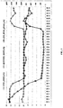
- Fig. 1 is a schematic diagram of an operation parameter curve of a wind generator set in a blade icing state according to an embodiment of the present application.
- the schematic diagram of the curve is the operation parameter curve of the wind generator set with rated power of 1500kW, wherein a horizontal axis represents a time axis, a square point curve represents a 10-minute average wind speed (wind-speed-avg) located on a primary axis (the vertical axis represents a speed axis on the left), a cross point curve represents a 10-minute average rotating speed of the generator set (generator-speed-avg) located on the primary axis (the vertical axis represents a rotating speed axis on the left), and a hollow dot curve represents 10-minute average power (gird-active-power-avg) located on a secondary axis (the vertical axis represents a power axis on the right).
- blades of the generator set are in a serious stalling state: for example, at a wind speed close to 10 m/s, the rotating speed of the generator set is maintained at the minimum rotating speed 10rpm, and the power is lower than 200kW.
- the main features of the generator set in the severe icing state are as follows: under the condition of a relatively high wind speed, the rotating speed of the generator set is close to the minimum rotating speed due to the stalling of the blades, and the power of the generator set drops with the rotating speed.
- the relatively high wind speed herein means that at this wind speed, the operation parameters of the generator set under the icing or limited power condition are significantly different from the operation parameters not under the icing or limited power condition.
- the relatively high wind speed can be 10m/s.
- the rotating speed of the generator set is the maximum rotating speed; if the blades stall due to the severe icing, the rotating speed may drop to the minimum rotating speed.
- the power of the generator set is the power in a free power generation state (for example, 1200kW) and the rotating speed of the generator set is the maximum rotating speed; and if a limited power value is a relatively low power, for example 400kW, then the actual power of the generator set is 400kW, and the rotating speed of the generator set is a low rotating speed corresponding to the limited power value 400kW.
- the maximum rotating speed and the minimum rotating speed herein can be understood as the own attributes of the wind generator set.
- Fig. 2 is a schematic diagram of a torque-rotating speed characteristic curve of a wind generator set under a limited power condition according to an embodiment of the present application.
- the horizontal coordinate represents the rotating speed and is denoted by the letter n
- the vertical coordinate represents the torque and is denoted by the letter T.
- the maximum limited rotating speed of the wind generator set operating under the limited power condition can be denoted by n_limit and is determined by the limited power value.
- n_limit When the wind generator set works under the limited power condition, at the relatively high wind speed, the rotating speed of the generator set is limited to n_limit, and the power is limited to the power corresponding to n_limit; while at a relatively low wind speed, the wind generator set is in the free power generation state, and the rotating speed is between the minimum rotating speed and the maximum limited rotating speed.
- the minimum rotating speed herein is denoted by n_min
- the maximum limited rotating speed is denoted by n_limit.
- a preset wind speed threshold is set in advance.
- the wind speed greater than the preset wind speed threshold can be understood as the relatively high wind speed mentioned above, while the wind speed smaller than the preset wind speed threshold can be understood as the relatively low wind speed mentioned above.
- the preset wind speed threshold is used as a judging condition for the identification of the blade icing state.
- the preset wind speed threshold may be manually set according to experience, or may be calculated by the following way: multiplying a wind speed value corresponding to the minimum torque of a constant rotating speed section in which the rotating speed is a preset maximum rotating speed n max in the torque-rotating speed characteristic curve under the limited power condition by a preset coefficient.
- Fig. 3 is a flowchart of a blade icing state identification method for a wind generator set according to an embodiment of the present application.
- the method may include the following steps: S310, setting a preset wind speed threshold and a preset rotating speed threshold, and setting the preset rotating speed threshold as a lower limit value of the maximum limited rotating speed of the wind generator set operating under a limited power condition; S320, obtaining a current wind speed and a current rotating speed of the wind generator set, comparing them with the preset wind speed threshold and the preset rotating speed threshold respectively, progressively increasing a blade icing possibility index when the current wind speed is greater than the preset wind speed threshold and the current rotating speed of the wind generator set is smaller than the preset rotating speed threshold, and otherwise, progressively decreasing the blade icing possibility index; and S330, determining that blades are iced up when the blade icing possibility index is greater than a preset index.
- the preset rotating speed threshold is greater than the minimum rotating speed of the generator set.
- the method may further include: monitoring/receiving an external environment index of the generator set, and comparing the external environment index of the generator set with a blade icing induction index to determine whether the external environment index of the generator set satisfies an icing induction condition.
- the flow of the method as shown in Fig. 3 is started.
- the external environment index of the generator set may be obtained in multiple manners.
- the external environment index of the generator set may be obtained by a sensor arranged outside of the generator set.
- the external environment index of the generator set may also be acquired from a database including the external environment index of the generator set, and a manually input measured external environment index of the generator set may also be directly received.
- the external environment index of the generator set may include temperature and humidity. For example, when the external environment temperature of the generator set is lower than 5°C and the relative humidity is higher than 90%, the blade icing state identification method as shown in Fig. 3 is started to be executed.
- the preset rotating speed threshold set in step S310 may be greater than the minimum rotating speed of the generator set and is smaller than an intermediate value between the minimum rotating speed and the maximum rotating speed of the generator set.
- the minimum rotating speed and the maximum rotating speed herein may be the minimum rotating speed and the maximum rotating speed corresponding to end points in the torque-rotating speed characteristic curve of the wind generator set in Fig. 2 .
- a value n0 may be set, and then the preset rotating speed threshold n_ref may be denoted by the maximum rotating speed n_min+ n0.
- the value n0 may be set to make n ref closer to n_min than n_max.
- a function of the preset rotating speed threshold n ref is to serve as a condition for determining the blade icing state of the generator set, and the other function is to set a lower limit value for the maximum limited rotating speed n_limit of the generator set operating under the limited power condition.
- n_limit is greater than n_ref
- n_limit may not be limited by n_ref
- n_limit is assigned as n_ref.
- the modified n limit may be sent to a farm-level energy management platform of wind generator sets.
- the farm-level energy management platform may adjust the limited power value delivered to a single wind generator set in real time according to the actual value of n limit, so as to avoid the situation that the single wind generator set is not controlled by the farm-level energy management platform.
- the modified n_limit may also be sent to a wind farm controller, which, for example, may be a wind farm controller having functions of controlling a wind farm and regulating normal powers.
- the method in the abovementioned embodiment may be executed by the wind farm controller. For example, a plurality of wind generator sets in the wind farm may be selected to perform the control of the abovementioned method so as to identify the blade icing state.
- the wind generator set is controlled by the abovementioned method, at a relatively high wind speed, that is, when the current wind speed is greater than the preset wind speed threshold, if the blades do not seriously stall due to icing, the rotating speed will not be lower than the preset wind speed threshold no matter the generator set is in the limited power state or not; if the blades seriously stall due to icing, the rotating speed will drop below the preset wind speed threshold, in which case the resistance of the blades is much larger than the lift and the icing load of the blades is very large, which seriously affects lives of the blades.
- the preset wind speed threshold is smaller than the wind speed value corresponding to the minimum torque of the constant rotating speed section in which the rotating speed is the preset maximum rotating speed n max in the torque-rotating speed characteristic curve of the wind generator set under the limited power condition.
- the preset wind speed threshold may be obtained by multiplying the wind speed value corresponding to the minimum torque of the constant rotating speed section in which the rotating speed is the preset maximum rotating speed n_max in the torque-rotating speed characteristic curve based on the wind speed under the limited power condition by the preset coefficient.
- the value of the preset coefficient herein may be between 0.5 and 1, e.g. 0.8.
- the rotating speed may be lower than the preset rotating speed threshold no matter whether the blades are iced or not.
- the generator set may continue to operate since the icing load of the blades may be relatively small.
- the icing state may be detected in other manners, for example, by considering a power-wind speed mismatch. As the judgment method by considering the power-wind speed mismatch under the condition of the relatively low wind speed is simple, no detailed description will be given in the embodiment of the present application. However, it does not prevent the combined implementation of the blade icing state identification method of the present application and the blade icing state identification method at the relatively low wind speed mentioned above.
- the preset index in S330 may be determined based on an updating period of the blade icing possibility index.
- the updating period of the blade icing possibility index is an execution period of the method in the above described embodiment and is usually a few milliseconds to tens of milliseconds. Every update of the blade icing possibility index may represent the blade icing risk at that moment.
- the period of time for the determination may be specifically defined by setting the preset index. For example, a counter may be set and initialized to 0.
- the value of the counter When the wind speed is greater than the preset wind speed threshold and the current rotating speed of the set is smaller than the preset rotating speed threshold, the value of the counter may be increased by 1; otherwise, the value may be decreased by 1. Then the determination may be carried out based on the value of the counter. If the value of the counter exceeds a limit value, it may be determined that the blades are iced up. In an example, when the value of the counter is smaller than 0, the value of the counter is limited to 0. If the period of time for the determination is defined to be 10 minutes, the preset index may be set to be tens of thousands to hundreds of thousands.
- the lower limit value of the maximum limited rotating speed is set for the wind generator set under the limited power condition so as to effectively distinguish the low rotating speed value under the limited power condition from the low rotating speed value during stalling caused by icing.
- it may be effectively determined whether the wind generator set is in the blade icing state while operating under the limited power condition, thus avoiding the risk of failure of the wind generator set due to being unable to identify the icing state.
- the blade icing state may be accurately identified during serious stalling caused by blade icing at the relatively high wind speed.
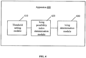
- Fig.4 is a schematic block diagram of a blade icing state identification apparatus for a wind generator set according to an embodiment of the present application.
- the blade icing state identification apparatus 400 includes a threshold setting module 410, an icing possibility index determination module 420 and an icing determination module 430.
- the threshold setting module 410 is configured to set a preset wind speed threshold and a preset rotating speed threshold, and set the preset rotating speed threshold as a lower limit value of the maximum limited rotating speed of the wind generator set operating under a limited power condition.
- the icing possibility index determination module 420 is configured to obtain a current wind speed and a current rotating speed of the wind generator set and compare the current wind speed and the current rotating speed of the wind generator set with the preset wind speed threshold and the preset rotating speed threshold respectively. When the current wind speed is greater than the preset wind speed threshold and the current rotating speed of the wind generator set is smaller than the preset rotating speed threshold, the icing possibility index determination module 420 progressively increases a blade icing possibility index. Otherwise, the icing possibility index determination module 420 progressively decreases the blade icing possibility index.
- the icing determination module 430 is configured to determine that blades are iced up when the blade icing possibility index is greater than a preset index.
- the apparatus further includes an environment determination module, configured to monitor/receive an external environment index of the generator set, compare the external environment index of the generator set with a blade icing induction index to determine whether the external environment index of the generator set satisfies an icing induction condition.
- the environment determination module may notify the threshold setting module to set the preset wind speed threshold and the preset rotating speed threshold and to set the preset rotating speed threshold as the lower limit value of the maximum limited rotating speed of the wind generator set operating under the limited power condition.
- the external environment index of the generator set may include temperature and humidity.
- the preset rotating speed threshold may be greater than the minimum rotating speed of the generator set and smaller than an intermediate value between the minimum rotating speed and the maximum rotating speed of the generator set. In an example, the preset rotating speed threshold is smaller than the wind speed value corresponding to the minimum torque of the constant rotating speed section of the preset maximum rotating speed in the torque-rotating speed characteristic curve of the generator set under the limited power condition. In an example, the preset index may be determined according to the updating period of the blade icing possibility index.
- the blade icing state identification apparatus 400 for the wind generator set according to the embodiment of the present application may correspond to an executor of the blade icing state identification method for the wind generator set according to the embodiment of the present application.
- the above mentioned and other operations and/or functions of various modules in the blade icing state identification apparatus 400 for the wind generator set respectively aim at realizing the corresponding processes of the method in Fig.3 , and thus will not be repeated herein for the purpose of conciseness.
- the lower limit value of the maximum limited rotating speed is set for the wind generator set under the limited power condition so as to effectively distinguish the low rotating speed value under the limited power condition from the low rotating speed value during stalling caused by icing.
- it may be effectively determined whether the wind generator set is in the blade icing state while operating under the limited power condition, thus avoiding the risk of failure of the wind generator set due to being unable to identify the icing state.
- the blade icing state may be accurately identified during serious stalling caused by blade icing at the relatively high wind speed.
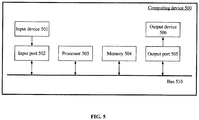
- Fig. 5 is a schematic block diagram of a blade icing state identification apparatus for a wind generator set according to an embodiment. As shown in Fig. 5 , at least a part of the blade icing state identification method for the wind generator set and the blade icing state identification apparatus for the wind generator set described with reference to Fig. 3 and Fig. 4 may be implemented by a computing device 500.
- the computing device 500 may include an input device 501, a processor 503 and a memory 504.
- the memory 504 is used for storing computer executable instructions; the processor 503 is used for executing the computer executable instructions stored in the memory, and the computer executable instruction causes the processor to execute the blade icing state identification method for the wind generator set mentioned above; and the input device 501 is used for obtaining the current wind speed and the current rotating speed of the generator set.
- the computing device 500 may further include an input port 502, an output port 505 and an output device 506.
- the input port 502, the processor 503, the memory 504, and the output port 505 are connected to one another through a bus 510; and the input device 501 and the output device 506 are connected to the bus 510 through the input port 502 and the output port 505 respectively so as to be connected with other components of the computing device 500.
- the output interface and the input interface may be denoted by I/O interfaces.
- the input device 501 receives input information from the outside and transmits the input information to the processor 503 through the input port 502; the processor 503 processes the input information based on the computer executable instructions stored in the memory 504 to generate output information, temporarily or permanently stores the output information in the memory 504, and then transmits the output information to the output device 506 through the output port 505; and the output device 506 outputs the output information to the outside of the computing device 500.
- the above mentioned memory 504 includes a mass memory for storing data or instructions.
- the memory 504 may include an HDD, a floppy disk drive, a flash memory, an optical disk, a magneto-optical disk, a magnetic tape or a universal serial bus (USB) drive or a combination of two or more thereof.
- the memory 504 may include a removable or non-removable (or fixed) medium.
- the memory 504 may be located at the inside or outside of the computing device 500.
- the memory 504 is a non-volatile solid state memory.
- the memory 504 includes a read only memory (ROM).
- the ROM may be a mask-programmed ROM, a programmable ROM (PROM), an erasable PROM (EPROM), an electrically erasable PROM (EEPROM), an electrically rewritable ROM (EAROM) or flash memory or a combination of two or more thereof.
- PROM programmable ROM
- EPROM erasable PROM
- EEPROM electrically erasable PROM
- EAROM electrically rewritable ROM
- the bus 510 includes hardware, software or both and couples the components of the computing device 500 together.
- the bus 510 may include an accelerated graphics port (AGP) or other graphics bus, an enhanced industry standard architecture (EISA) bus, a front side bus (FSB), a hypertransport (HT) interconnection, an industry standard architecture (ISA) bus, an infinite bandwidth interconnection, a low pin count (LPC) bus, a memory bus, a micro channel architecture (MCA) bus, a peripheral component interconnection (PCI) bus, a PCI-Express (PCI-X) bus, a serial advanced technology attachment (SATA) bus, a Video Electronics Standards Association part (VLB) bus, or other suitable buses, or a combination of two or more thereof.
- the bus 510 may include one or more buses 510.
- the present application describes and illustrates a particular bus, the present application considers any suitable buses or interconnections.
- the input device 501 receives the current wind speed and the current rotating speed of the generator set.
- the I/O interface connected with the output device may include hardware, software or both and provides one or more interfaces for the communication between the computing device 500 and one or more I/O devices.
- the computing device 500 may include one or more of these I/O devices.
- One or more of these I/O devices may allow the communication between a person and the computer system 500.
- the I/O device may include a keyboard, a keypad, a microphone, a monitor, a mouse, a printer, a scanner, a loudspeaker, a still camera, a contact pin, a handwriting board, a touch screen, a trackball, a video camera, another suitable I/O device, or a combination of two or more thereof.
- the I/O device may include one or more sensors.
- the embodiment of the present application considers any suitable I/O devices and any suitable I/O interfaces applicable to the apparatus. Under appropriate conditions, the I/O interface may include one or more devices or software drivers capable of allowing the processor 503 to drive one or more of these I/O devices.
- the I/O interface may include one or more I/O interfaces.
- the embodiment of the present application describes and illustrates specific I/O interfaces, the embodiment of the present application considers any suitable I/O interface.
- the processor 503 obtains the current wind speed and the current rotating speed of the wind generator set, compares them with the preset wind speed threshold and the preset rotating speed threshold respectively, progressively increases the blade icing possibility index when the current wind speed is greater than the preset wind speed threshold and the current rotating speed of the wind generator set is smaller than the preset rotating speed threshold, and otherwise, progressively decreases the blade icing possibility index. Then, the icing state identification result may be output via the output port 505 and the output device 506.
- the blade icing state identification apparatus for the wind generator set may be implemented to include the memory 504 for storing the computer executable instructions and the processor 503 for implementing the blade icing state identification method for the wind generator set and the blade icing state identification apparatus for the wind generator set described in combination with Fig. 3 and Fig. 4 when executing the computer executable instruction .
- the computer executable instruction may include one or more semiconductor-based or other integrated circuits (ICs) (for example, a field programmable gate array (FPGA) or an specific IC (ASIC)), hard disk drives (HDDs), hybrid hard disk drives (HHDs), optical disks, optical disk drives (ODDs), magneto-optical disks, magneto-optical disk drives, floppy disks, floppy disk drives (FDDs), magnetic tapes, holographic storage media, solid state drives (SSDs), RAM drives, secure digital cards or drives or other suitable computer readable non-transitory storage media or a combination of two or more thereof.
- ICs semiconductor-based or other integrated circuits
- FPGA field programmable gate array
- ASIC specific IC
Landscapes
- Engineering & Computer Science (AREA)
- Life Sciences & Earth Sciences (AREA)
- Sustainable Development (AREA)
- Sustainable Energy (AREA)
- Chemical & Material Sciences (AREA)
- Combustion & Propulsion (AREA)
- Mechanical Engineering (AREA)
- General Engineering & Computer Science (AREA)
- Power Engineering (AREA)
- Wind Motors (AREA)
- Control Of Eletrric Generators (AREA)
Applications Claiming Priority (2)
| Application Number | Priority Date | Filing Date | Title |
|---|---|---|---|
| CN201611078317.2A CN108119319B (zh) | 2016-11-29 | 2016-11-29 | 风力发电机组叶片结冰状态识别方法及装置 |
| PCT/CN2017/092073 WO2018099083A1 (fr) | 2016-11-29 | 2017-07-06 | Procédé et dispositif d'identification d'état de givrage de pale d'éolienne |
Publications (3)
| Publication Number | Publication Date |
|---|---|
| EP3460237A1 true EP3460237A1 (fr) | 2019-03-27 |
| EP3460237A4 EP3460237A4 (fr) | 2019-07-24 |
| EP3460237B1 EP3460237B1 (fr) | 2021-02-17 |
Family
ID=62226953
Family Applications (1)
| Application Number | Title | Priority Date | Filing Date |
|---|---|---|---|
| EP17818415.6A Active EP3460237B1 (fr) | 2016-11-29 | 2017-07-06 | Procédé et dispositif d'identification d'état de givrage de pale d'éolienne |
Country Status (7)
| Country | Link |
|---|---|
| US (1) | US10767634B2 (fr) |
| EP (1) | EP3460237B1 (fr) |
| KR (1) | KR102011589B1 (fr) |
| CN (1) | CN108119319B (fr) |
| AU (1) | AU2017294578B2 (fr) |
| ES (1) | ES2865438T3 (fr) |
| WO (1) | WO2018099083A1 (fr) |
Cited By (1)
| Publication number | Priority date | Publication date | Assignee | Title |
|---|---|---|---|---|
| US12540600B2 (en) | 2023-04-04 | 2026-02-03 | Nordex Energy Se & Co. Kg | Method for operating a wind turbine and wind turbine |
Families Citing this family (15)
| Publication number | Priority date | Publication date | Assignee | Title |
|---|---|---|---|---|
| CN109026563B (zh) * | 2018-07-24 | 2019-12-27 | 上海电力学院 | 一种基于特征选择和XGBoost的风机叶片结冰预测方法 |
| CN110285027B (zh) * | 2019-04-30 | 2020-08-18 | 长沙理工大学 | 风力发电机叶片除冰方法、除冰系统及终端设备 |
| CN110273818B (zh) * | 2019-06-10 | 2020-12-18 | 浙江大学 | 一种基于轴变换粗细度分类的风机叶片结冰故障监测方法 |
| CN112283025B (zh) * | 2020-10-14 | 2021-10-12 | 明阳智慧能源集团股份公司 | 一种避免风电机组限功率运行在共振区域的控制方法 |
| CN114676510B (zh) * | 2020-12-24 | 2024-12-13 | 江苏金风科技有限公司 | 风机的叶片外形参数确定方法、装置、设备及介质 |
| CN113007041A (zh) * | 2021-03-02 | 2021-06-22 | 山东中车风电有限公司 | 一种风电机组叶片结冰检测系统及检测方法 |
| CN113803223B (zh) * | 2021-08-11 | 2022-12-20 | 明阳智慧能源集团股份公司 | 一种风机叶片结冰状态实时监测方法、系统、介质及设备 |
| CN113847216B (zh) * | 2021-10-14 | 2023-09-26 | 远景智能国际私人投资有限公司 | 风机叶片的状态预测方法、装置、设备及存储介质 |
| CN115585107B (zh) * | 2022-10-27 | 2025-11-21 | 湖南防灾科技有限公司 | 风力发电机组叶片冻雾覆冰厚度的预测方法和系统 |
| CN116313196A (zh) * | 2023-01-12 | 2023-06-23 | 华能海南昌江核电有限公司 | 设备状态的监测方法以及装置、存储介质、电子设备 |
| CN119122761B (zh) * | 2023-06-12 | 2025-12-19 | 北京金风科创风电设备有限公司 | 风力发电机组覆冰状态的检测方法及装置 |
| CN117028146B (zh) * | 2023-08-21 | 2025-11-25 | 华能赫章风力发电有限公司 | 覆冰条件下风力发电机组转速转矩控制方法及相关设备 |
| CN117108462B (zh) * | 2023-08-24 | 2025-12-05 | 东方电气风电股份有限公司 | 一种风力发电机组叶片结冰识别方法和装置 |
| CN119353174A (zh) * | 2024-12-03 | 2025-01-24 | 福氏工业(北京)有限公司 | 一种风力发电机组叶片结冰状态的监测控制方法 |
| CN120701529B (zh) * | 2025-08-28 | 2025-11-04 | 西安热工研究院有限公司 | 一种风电叶片覆冰实验装置及离心脱冰控制方法 |
Family Cites Families (21)
| Publication number | Priority date | Publication date | Assignee | Title |
|---|---|---|---|---|
| US6890152B1 (en) * | 2003-10-03 | 2005-05-10 | General Electric Company | Deicing device for wind turbine blades |
| US7086834B2 (en) * | 2004-06-10 | 2006-08-08 | General Electric Company | Methods and apparatus for rotor blade ice detection |
| US8050887B2 (en) * | 2008-12-22 | 2011-11-01 | General Electric Company | Method and system for determining a potential for icing on a wind turbine blade |
| SE535025C2 (sv) * | 2009-06-08 | 2012-03-20 | Ge Wind Energy Norway As | Vindkraftverk och en metod för att driva ett vindkraftverk |
| US9458834B2 (en) | 2010-03-23 | 2016-10-04 | Vestas Wind Systems A/S | Method for de-icing the blades of a wind turbine and a wind turbine with a de-icing system |
| CA2795881C (fr) | 2010-04-19 | 2015-11-24 | Wobben Properties Gmbh | Procede de degivrage d'une pale de turbine eoliennee |
| US20120226485A1 (en) * | 2011-03-03 | 2012-09-06 | Inventus Holdings, Llc | Methods for predicting the formation of wind turbine blade ice |
| DE102011077129A1 (de) * | 2011-06-07 | 2012-12-13 | Aloys Wobben | Verfahren zum Betreiben einer Windenergieanlage |
| CN202280571U (zh) * | 2011-10-13 | 2012-06-20 | 国电联合动力技术有限公司 | 风力发电机组冰载运行优化控制系统 |
| US8292579B2 (en) * | 2011-11-03 | 2012-10-23 | General Electric Company | Method and system for deicing wind turbine rotor blades with induced torque |
| EP2795120A2 (fr) * | 2011-12-22 | 2014-10-29 | Vestas Wind Systems A/S | Pale de turbine éolienne dotée d'un détecteur d'accumulation de glace |
| DK2647838T3 (en) * | 2012-04-04 | 2015-01-19 | Siemens Ag | Method of operating a wind turbine with a rotor hub supporting at least one rotor blade |
| EP2679809A1 (fr) * | 2012-06-28 | 2014-01-01 | Siemens Aktiengesellschaft | Procédé et dispositif permettant de répondre à un événement du réseau, par exemple une baisse rapide de la fréquence, en combinant une réponse à la demande, une réponse inertielle et une réserve de rotation |
| CN102817780B (zh) * | 2012-08-22 | 2015-06-10 | 南京风电科技有限公司 | 风力发电机组结冰控制装置及控制方法 |
| CN103603769B (zh) * | 2013-11-23 | 2016-01-20 | 大连尚能科技发展有限公司 | 一种变桨矩风力发电机组的风机叶片结冰自检测方法 |
| CN105089929B (zh) * | 2014-05-21 | 2018-07-10 | 南车株洲电力机车研究所有限公司 | 风力发电机组叶片结冰检测系统及其方法 |
| ES2624606T3 (es) * | 2014-07-23 | 2017-07-17 | Nordex Energy Gmbh | Procedimiento para el examen de un sistema de detección de hielo en las palas de rotor, así como sistema de detección de hielo en las palas de rotor e instalación de energía eólica para la realización del procedimiento |
| CN104454386B (zh) | 2014-11-24 | 2017-08-29 | 北京金风科创风电设备有限公司 | 风力发电机组结冰控制方法和装置 |
| CN104832371B (zh) * | 2015-05-28 | 2017-10-24 | 大唐山东烟台电力开发有限公司 | 一种风力发电机组控制方法和系统 |
| DK3165766T3 (da) * | 2015-11-06 | 2021-08-23 | Nordex Energy Spain S A | Vindmølle og fremgangsmåde til fjernelse af is i vindmøller |
| CN105508152B (zh) * | 2015-12-31 | 2018-10-23 | 北京金风科创风电设备有限公司 | 叶片结冰模型的构建方法、结冰状态的监测方法和装置 |
-
2016
- 2016-11-29 CN CN201611078317.2A patent/CN108119319B/zh active Active
-
2017
- 2017-07-06 AU AU2017294578A patent/AU2017294578B2/en active Active
- 2017-07-06 ES ES17818415T patent/ES2865438T3/es active Active
- 2017-07-06 EP EP17818415.6A patent/EP3460237B1/fr active Active
- 2017-07-06 WO PCT/CN2017/092073 patent/WO2018099083A1/fr not_active Ceased
- 2017-07-06 US US15/741,912 patent/US10767634B2/en active Active
- 2017-07-06 KR KR1020177033041A patent/KR102011589B1/ko active Active
Cited By (1)
| Publication number | Priority date | Publication date | Assignee | Title |
|---|---|---|---|---|
| US12540600B2 (en) | 2023-04-04 | 2026-02-03 | Nordex Energy Se & Co. Kg | Method for operating a wind turbine and wind turbine |
Also Published As
| Publication number | Publication date |
|---|---|
| WO2018099083A1 (fr) | 2018-06-07 |
| AU2017294578A1 (en) | 2018-06-14 |
| EP3460237B1 (fr) | 2021-02-17 |
| CN108119319B (zh) | 2020-02-11 |
| ES2865438T3 (es) | 2021-10-15 |
| KR102011589B1 (ko) | 2019-08-16 |
| KR20180075432A (ko) | 2018-07-04 |
| US20190003461A1 (en) | 2019-01-03 |
| EP3460237A4 (fr) | 2019-07-24 |
| CN108119319A (zh) | 2018-06-05 |
| US10767634B2 (en) | 2020-09-08 |
| AU2017294578B2 (en) | 2019-05-30 |
Similar Documents
| Publication | Publication Date | Title |
|---|---|---|
| AU2017294578B2 (en) | Blade icing state identification method and apparatus for wind generator set | |
| AU2020399503B2 (en) | Method and apparatus for detecting yaw-to-wind abnormality, and device and storage medium thereof | |
| US20150337802A1 (en) | System and method for pitch fault detection | |
| EP3228862B1 (fr) | Procédé, dispositif et système pour commander une correction d'alignement de vent de système de générateur à turbine éolienne | |
| EP3303834B1 (fr) | Procédé de commande d'une éolienne prenant en compte une valeur de fatigue | |
| US12123399B2 (en) | Load control method and apparatus for wind turbine generator system | |
| US10968892B2 (en) | Controlling wind turbine | |
| CN111706464A (zh) | 风力发电机组的控制方法、装置及介质 | |
| EP3263890A1 (fr) | Procédés et systèmes de commande prédictive d'éoliennes | |
| EP4650594A1 (fr) | Procédé et dispositif de commande à pas variable pour ensemble générateur éolien | |
| WO2019066934A1 (fr) | Surveillance de rendement d'éolienne | |
| ES2981255T3 (es) | Disposición de control de turbina eólica | |
| CN117406102A (zh) | 电池放电功率的控制方法、装置、车辆及电子设备 | |
| CN113027674B (zh) | 风力发电机组的控制方法及其装置 | |
| CN110929800B (zh) | 一种基于sax算法的商业体异常用电检测方法 | |
| EP3667069A1 (fr) | Procédé et organe de commande pour la commande à pleine puissance d'une éolienne | |
| CN119572413B (zh) | 风电机组的控制方法、装置、系统、介质及产品 | |
| CN114987195B (zh) | 一种主动进气格栅的控制方法、装置、电子设备及介质 | |
| CN119401581B (zh) | 一种输电线路载流量额定值的动态调整方法、装置、电子设备及存储介质 | |
| CN116877338B (zh) | 一种风机叶片控制方法、装置、设备及存储介质 | |
| CN112943530B (zh) | 风力发电机组的控制方法及其装置 | |
| CN118675297A (zh) | 风力发电机超速预警方法、装置、设备、介质及产品 | |
| CN121769851A (zh) | 受极端天气影响的风力发电预测功率校正方法、装置、设备以及介质 | |
| CN115298437A (zh) | 用于控制风力涡轮机的操作的方法和系统 | |
| CN118544767A (zh) | 离散挡位加热器闭环控制的方法及装置、车辆、电子设备 |
Legal Events
| Date | Code | Title | Description |
|---|---|---|---|
| STAA | Information on the status of an ep patent application or granted ep patent |
Free format text: STATUS: UNKNOWN |
|
| STAA | Information on the status of an ep patent application or granted ep patent |
Free format text: STATUS: THE INTERNATIONAL PUBLICATION HAS BEEN MADE |
|
| PUAI | Public reference made under article 153(3) epc to a published international application that has entered the european phase |
Free format text: ORIGINAL CODE: 0009012 |
|
| STAA | Information on the status of an ep patent application or granted ep patent |
Free format text: STATUS: REQUEST FOR EXAMINATION WAS MADE |
|
| 17P | Request for examination filed |
Effective date: 20180205 |
|
| AK | Designated contracting states |
Kind code of ref document: A1 Designated state(s): AL AT BE BG CH CY CZ DE DK EE ES FI FR GB GR HR HU IE IS IT LI LT LU LV MC MK MT NL NO PL PT RO RS SE SI SK SM TR |
|
| AX | Request for extension of the european patent |
Extension state: BA ME |
|
| RAP1 | Party data changed (applicant data changed or rights of an application transferred) |
Owner name: BEIJING GOLDWIND SCIENCE & CREATION WINDPOWER EQUI |
|
| A4 | Supplementary search report drawn up and despatched |
Effective date: 20190626 |
|
| RIC1 | Information provided on ipc code assigned before grant |
Ipc: F03D 80/40 20160101AFI20190620BHEP Ipc: F03D 17/00 20160101ALI20190620BHEP |
|
| DAV | Request for validation of the european patent (deleted) | ||
| DAX | Request for extension of the european patent (deleted) | ||
| STAA | Information on the status of an ep patent application or granted ep patent |
Free format text: STATUS: EXAMINATION IS IN PROGRESS |
|
| 17Q | First examination report despatched |
Effective date: 20200325 |
|
| GRAP | Despatch of communication of intention to grant a patent |
Free format text: ORIGINAL CODE: EPIDOSNIGR1 |
|
| STAA | Information on the status of an ep patent application or granted ep patent |
Free format text: STATUS: GRANT OF PATENT IS INTENDED |
|
| INTG | Intention to grant announced |
Effective date: 20200918 |
|
| GRAS | Grant fee paid |
Free format text: ORIGINAL CODE: EPIDOSNIGR3 |
|
| GRAA | (expected) grant |
Free format text: ORIGINAL CODE: 0009210 |
|
| STAA | Information on the status of an ep patent application or granted ep patent |
Free format text: STATUS: THE PATENT HAS BEEN GRANTED |
|
| AK | Designated contracting states |
Kind code of ref document: B1 Designated state(s): AL AT BE BG CH CY CZ DE DK EE ES FI FR GB GR HR HU IE IS IT LI LT LU LV MC MK MT NL NO PL PT RO RS SE SI SK SM TR |
|
| REG | Reference to a national code |
Ref country code: GB Ref legal event code: FG4D |
|
| REG | Reference to a national code |
Ref country code: CH Ref legal event code: EP |
|
| REG | Reference to a national code |
Ref country code: DE Ref legal event code: R096 Ref document number: 602017032900 Country of ref document: DE |
|
| REG | Reference to a national code |
Ref country code: AT Ref legal event code: REF Ref document number: 1361825 Country of ref document: AT Kind code of ref document: T Effective date: 20210315 |
|
| REG | Reference to a national code |
Ref country code: IE Ref legal event code: FG4D |
|
| REG | Reference to a national code |
Ref country code: GR Ref legal event code: EP Ref document number: 20210400957 Country of ref document: GR Effective date: 20210519 |
|
| REG | Reference to a national code |
Ref country code: LT Ref legal event code: MG9D |
|
| REG | Reference to a national code |
Ref country code: NL Ref legal event code: MP Effective date: 20210217 |
|
| PG25 | Lapsed in a contracting state [announced via postgrant information from national office to epo] |
Ref country code: HR Free format text: LAPSE BECAUSE OF FAILURE TO SUBMIT A TRANSLATION OF THE DESCRIPTION OR TO PAY THE FEE WITHIN THE PRESCRIBED TIME-LIMIT Effective date: 20210217 Ref country code: FI Free format text: LAPSE BECAUSE OF FAILURE TO SUBMIT A TRANSLATION OF THE DESCRIPTION OR TO PAY THE FEE WITHIN THE PRESCRIBED TIME-LIMIT Effective date: 20210217 Ref country code: PT Free format text: LAPSE BECAUSE OF FAILURE TO SUBMIT A TRANSLATION OF THE DESCRIPTION OR TO PAY THE FEE WITHIN THE PRESCRIBED TIME-LIMIT Effective date: 20210617 Ref country code: NO Free format text: LAPSE BECAUSE OF FAILURE TO SUBMIT A TRANSLATION OF THE DESCRIPTION OR TO PAY THE FEE WITHIN THE PRESCRIBED TIME-LIMIT Effective date: 20210517 Ref country code: BG Free format text: LAPSE BECAUSE OF FAILURE TO SUBMIT A TRANSLATION OF THE DESCRIPTION OR TO PAY THE FEE WITHIN THE PRESCRIBED TIME-LIMIT Effective date: 20210517 Ref country code: LT Free format text: LAPSE BECAUSE OF FAILURE TO SUBMIT A TRANSLATION OF THE DESCRIPTION OR TO PAY THE FEE WITHIN THE PRESCRIBED TIME-LIMIT Effective date: 20210217 |
|
| REG | Reference to a national code |
Ref country code: AT Ref legal event code: MK05 Ref document number: 1361825 Country of ref document: AT Kind code of ref document: T Effective date: 20210217 |
|
| PG25 | Lapsed in a contracting state [announced via postgrant information from national office to epo] |
Ref country code: LV Free format text: LAPSE BECAUSE OF FAILURE TO SUBMIT A TRANSLATION OF THE DESCRIPTION OR TO PAY THE FEE WITHIN THE PRESCRIBED TIME-LIMIT Effective date: 20210217 Ref country code: NL Free format text: LAPSE BECAUSE OF FAILURE TO SUBMIT A TRANSLATION OF THE DESCRIPTION OR TO PAY THE FEE WITHIN THE PRESCRIBED TIME-LIMIT Effective date: 20210217 Ref country code: RS Free format text: LAPSE BECAUSE OF FAILURE TO SUBMIT A TRANSLATION OF THE DESCRIPTION OR TO PAY THE FEE WITHIN THE PRESCRIBED TIME-LIMIT Effective date: 20210217 Ref country code: PL Free format text: LAPSE BECAUSE OF FAILURE TO SUBMIT A TRANSLATION OF THE DESCRIPTION OR TO PAY THE FEE WITHIN THE PRESCRIBED TIME-LIMIT Effective date: 20210217 Ref country code: SE Free format text: LAPSE BECAUSE OF FAILURE TO SUBMIT A TRANSLATION OF THE DESCRIPTION OR TO PAY THE FEE WITHIN THE PRESCRIBED TIME-LIMIT Effective date: 20210217 |
|
| PG25 | Lapsed in a contracting state [announced via postgrant information from national office to epo] |
Ref country code: IS Free format text: LAPSE BECAUSE OF FAILURE TO SUBMIT A TRANSLATION OF THE DESCRIPTION OR TO PAY THE FEE WITHIN THE PRESCRIBED TIME-LIMIT Effective date: 20210617 |
|
| REG | Reference to a national code |
Ref country code: ES Ref legal event code: FG2A Ref document number: 2865438 Country of ref document: ES Kind code of ref document: T3 Effective date: 20211015 |
|
| PG25 | Lapsed in a contracting state [announced via postgrant information from national office to epo] |
Ref country code: SM Free format text: LAPSE BECAUSE OF FAILURE TO SUBMIT A TRANSLATION OF THE DESCRIPTION OR TO PAY THE FEE WITHIN THE PRESCRIBED TIME-LIMIT Effective date: 20210217 Ref country code: AT Free format text: LAPSE BECAUSE OF FAILURE TO SUBMIT A TRANSLATION OF THE DESCRIPTION OR TO PAY THE FEE WITHIN THE PRESCRIBED TIME-LIMIT Effective date: 20210217 Ref country code: CZ Free format text: LAPSE BECAUSE OF FAILURE TO SUBMIT A TRANSLATION OF THE DESCRIPTION OR TO PAY THE FEE WITHIN THE PRESCRIBED TIME-LIMIT Effective date: 20210217 Ref country code: EE Free format text: LAPSE BECAUSE OF FAILURE TO SUBMIT A TRANSLATION OF THE DESCRIPTION OR TO PAY THE FEE WITHIN THE PRESCRIBED TIME-LIMIT Effective date: 20210217 |
|
| REG | Reference to a national code |
Ref country code: DE Ref legal event code: R097 Ref document number: 602017032900 Country of ref document: DE |
|
| PG25 | Lapsed in a contracting state [announced via postgrant information from national office to epo] |
Ref country code: RO Free format text: LAPSE BECAUSE OF FAILURE TO SUBMIT A TRANSLATION OF THE DESCRIPTION OR TO PAY THE FEE WITHIN THE PRESCRIBED TIME-LIMIT Effective date: 20210217 Ref country code: SK Free format text: LAPSE BECAUSE OF FAILURE TO SUBMIT A TRANSLATION OF THE DESCRIPTION OR TO PAY THE FEE WITHIN THE PRESCRIBED TIME-LIMIT Effective date: 20210217 Ref country code: DK Free format text: LAPSE BECAUSE OF FAILURE TO SUBMIT A TRANSLATION OF THE DESCRIPTION OR TO PAY THE FEE WITHIN THE PRESCRIBED TIME-LIMIT Effective date: 20210217 |
|
| PLBE | No opposition filed within time limit |
Free format text: ORIGINAL CODE: 0009261 |
|
| STAA | Information on the status of an ep patent application or granted ep patent |
Free format text: STATUS: NO OPPOSITION FILED WITHIN TIME LIMIT |
|
| 26N | No opposition filed |
Effective date: 20211118 |
|
| PG25 | Lapsed in a contracting state [announced via postgrant information from national office to epo] |
Ref country code: AL Free format text: LAPSE BECAUSE OF FAILURE TO SUBMIT A TRANSLATION OF THE DESCRIPTION OR TO PAY THE FEE WITHIN THE PRESCRIBED TIME-LIMIT Effective date: 20210217 |
|
| REG | Reference to a national code |
Ref country code: DE Ref legal event code: R119 Ref document number: 602017032900 Country of ref document: DE |
|
| PG25 | Lapsed in a contracting state [announced via postgrant information from national office to epo] |
Ref country code: SI Free format text: LAPSE BECAUSE OF FAILURE TO SUBMIT A TRANSLATION OF THE DESCRIPTION OR TO PAY THE FEE WITHIN THE PRESCRIBED TIME-LIMIT Effective date: 20210217 |
|
| REG | Reference to a national code |
Ref country code: CH Ref legal event code: PL |
|
| GBPC | Gb: european patent ceased through non-payment of renewal fee |
Effective date: 20210706 |
|
| PG25 | Lapsed in a contracting state [announced via postgrant information from national office to epo] |
Ref country code: MC Free format text: LAPSE BECAUSE OF FAILURE TO SUBMIT A TRANSLATION OF THE DESCRIPTION OR TO PAY THE FEE WITHIN THE PRESCRIBED TIME-LIMIT Effective date: 20210217 |
|
| REG | Reference to a national code |
Ref country code: BE Ref legal event code: MM Effective date: 20210731 |
|
| PG25 | Lapsed in a contracting state [announced via postgrant information from national office to epo] |
Ref country code: LI Free format text: LAPSE BECAUSE OF NON-PAYMENT OF DUE FEES Effective date: 20210731 Ref country code: GB Free format text: LAPSE BECAUSE OF NON-PAYMENT OF DUE FEES Effective date: 20210706 Ref country code: DE Free format text: LAPSE BECAUSE OF NON-PAYMENT OF DUE FEES Effective date: 20220201 Ref country code: CH Free format text: LAPSE BECAUSE OF NON-PAYMENT OF DUE FEES Effective date: 20210731 |
|
| PG25 | Lapsed in a contracting state [announced via postgrant information from national office to epo] |
Ref country code: IS Free format text: LAPSE BECAUSE OF FAILURE TO SUBMIT A TRANSLATION OF THE DESCRIPTION OR TO PAY THE FEE WITHIN THE PRESCRIBED TIME-LIMIT Effective date: 20210617 Ref country code: LU Free format text: LAPSE BECAUSE OF NON-PAYMENT OF DUE FEES Effective date: 20210706 Ref country code: FR Free format text: LAPSE BECAUSE OF NON-PAYMENT OF DUE FEES Effective date: 20210731 |
|
| PG25 | Lapsed in a contracting state [announced via postgrant information from national office to epo] |
Ref country code: IE Free format text: LAPSE BECAUSE OF NON-PAYMENT OF DUE FEES Effective date: 20210706 Ref country code: BE Free format text: LAPSE BECAUSE OF NON-PAYMENT OF DUE FEES Effective date: 20210731 |
|
| P01 | Opt-out of the competence of the unified patent court (upc) registered |
Effective date: 20230411 |
|
| PG25 | Lapsed in a contracting state [announced via postgrant information from national office to epo] |
Ref country code: CY Free format text: LAPSE BECAUSE OF FAILURE TO SUBMIT A TRANSLATION OF THE DESCRIPTION OR TO PAY THE FEE WITHIN THE PRESCRIBED TIME-LIMIT Effective date: 20210217 |
|
| PG25 | Lapsed in a contracting state [announced via postgrant information from national office to epo] |
Ref country code: HU Free format text: LAPSE BECAUSE OF FAILURE TO SUBMIT A TRANSLATION OF THE DESCRIPTION OR TO PAY THE FEE WITHIN THE PRESCRIBED TIME-LIMIT; INVALID AB INITIO Effective date: 20170706 |
|
| PG25 | Lapsed in a contracting state [announced via postgrant information from national office to epo] |
Ref country code: MK Free format text: LAPSE BECAUSE OF FAILURE TO SUBMIT A TRANSLATION OF THE DESCRIPTION OR TO PAY THE FEE WITHIN THE PRESCRIBED TIME-LIMIT Effective date: 20210217 |
|
| PG25 | Lapsed in a contracting state [announced via postgrant information from national office to epo] |
Ref country code: MT Free format text: LAPSE BECAUSE OF FAILURE TO SUBMIT A TRANSLATION OF THE DESCRIPTION OR TO PAY THE FEE WITHIN THE PRESCRIBED TIME-LIMIT Effective date: 20210217 |
|
| PGFP | Annual fee paid to national office [announced via postgrant information from national office to epo] |
Ref country code: GR Payment date: 20250618 Year of fee payment: 9 |
|
| PGFP | Annual fee paid to national office [announced via postgrant information from national office to epo] |
Ref country code: ES Payment date: 20250807 Year of fee payment: 9 |
|
| PGFP | Annual fee paid to national office [announced via postgrant information from national office to epo] |
Ref country code: TR Payment date: 20250702 Year of fee payment: 9 Ref country code: IT Payment date: 20250623 Year of fee payment: 9 |