EP3460263B1 - Vis à vissage rapide - Google Patents
Vis à vissage rapide Download PDFInfo
- Publication number
- EP3460263B1 EP3460263B1 EP18188382.8A EP18188382A EP3460263B1 EP 3460263 B1 EP3460263 B1 EP 3460263B1 EP 18188382 A EP18188382 A EP 18188382A EP 3460263 B1 EP3460263 B1 EP 3460263B1
- Authority
- EP
- European Patent Office
- Prior art keywords
- threads
- auxiliary
- main
- shank
- speedy
- Prior art date
- Legal status (The legal status is an assumption and is not a legal conclusion. Google has not performed a legal analysis and makes no representation as to the accuracy of the status listed.)
- Active
Links
- 238000005553 drilling Methods 0.000 claims description 27
- 230000000630 rising effect Effects 0.000 claims description 2
- 229920002522 Wood fibre Polymers 0.000 description 16
- 239000002023 wood Substances 0.000 description 16
- 239000002025 wood fiber Substances 0.000 description 16
- 230000000694 effects Effects 0.000 description 7
- 238000005336 cracking Methods 0.000 description 3
- 230000009977 dual effect Effects 0.000 description 3
- 230000002596 correlated effect Effects 0.000 description 1
- 230000003247 decreasing effect Effects 0.000 description 1
Images


Classifications
-
- F—MECHANICAL ENGINEERING; LIGHTING; HEATING; WEAPONS; BLASTING
- F16—ENGINEERING ELEMENTS AND UNITS; GENERAL MEASURES FOR PRODUCING AND MAINTAINING EFFECTIVE FUNCTIONING OF MACHINES OR INSTALLATIONS; THERMAL INSULATION IN GENERAL
- F16B—DEVICES FOR FASTENING OR SECURING CONSTRUCTIONAL ELEMENTS OR MACHINE PARTS TOGETHER, e.g. NAILS, BOLTS, CIRCLIPS, CLAMPS, CLIPS OR WEDGES; JOINTS OR JOINTING
- F16B25/00—Screws that cut thread in the body into which they are screwed, e.g. wood screws
- F16B25/10—Screws performing an additional function to thread-forming, e.g. drill screws or self-piercing screws
- F16B25/103—Screws performing an additional function to thread-forming, e.g. drill screws or self-piercing screws by means of a drilling screw-point, i.e. with a cutting and material removing action
-
- F—MECHANICAL ENGINEERING; LIGHTING; HEATING; WEAPONS; BLASTING
- F16—ENGINEERING ELEMENTS AND UNITS; GENERAL MEASURES FOR PRODUCING AND MAINTAINING EFFECTIVE FUNCTIONING OF MACHINES OR INSTALLATIONS; THERMAL INSULATION IN GENERAL
- F16B—DEVICES FOR FASTENING OR SECURING CONSTRUCTIONAL ELEMENTS OR MACHINE PARTS TOGETHER, e.g. NAILS, BOLTS, CIRCLIPS, CLAMPS, CLIPS OR WEDGES; JOINTS OR JOINTING
- F16B25/00—Screws that cut thread in the body into which they are screwed, e.g. wood screws
- F16B25/001—Screws that cut thread in the body into which they are screwed, e.g. wood screws characterised by the material of the body into which the screw is screwed
- F16B25/0015—Screws that cut thread in the body into which they are screwed, e.g. wood screws characterised by the material of the body into which the screw is screwed the material being a soft organic material, e.g. wood or plastic
-
- F—MECHANICAL ENGINEERING; LIGHTING; HEATING; WEAPONS; BLASTING
- F16—ENGINEERING ELEMENTS AND UNITS; GENERAL MEASURES FOR PRODUCING AND MAINTAINING EFFECTIVE FUNCTIONING OF MACHINES OR INSTALLATIONS; THERMAL INSULATION IN GENERAL
- F16B—DEVICES FOR FASTENING OR SECURING CONSTRUCTIONAL ELEMENTS OR MACHINE PARTS TOGETHER, e.g. NAILS, BOLTS, CIRCLIPS, CLAMPS, CLIPS OR WEDGES; JOINTS OR JOINTING
- F16B25/00—Screws that cut thread in the body into which they are screwed, e.g. wood screws
- F16B25/0036—Screws that cut thread in the body into which they are screwed, e.g. wood screws characterised by geometric details of the screw
- F16B25/0042—Screws that cut thread in the body into which they are screwed, e.g. wood screws characterised by geometric details of the screw characterised by the geometry of the thread, the thread being a ridge wrapped around the shaft of the screw
- F16B25/0052—Screws that cut thread in the body into which they are screwed, e.g. wood screws characterised by geometric details of the screw characterised by the geometry of the thread, the thread being a ridge wrapped around the shaft of the screw the ridge having indentations, notches or the like in order to improve the cutting behaviour
-
- F—MECHANICAL ENGINEERING; LIGHTING; HEATING; WEAPONS; BLASTING
- F16—ENGINEERING ELEMENTS AND UNITS; GENERAL MEASURES FOR PRODUCING AND MAINTAINING EFFECTIVE FUNCTIONING OF MACHINES OR INSTALLATIONS; THERMAL INSULATION IN GENERAL
- F16B—DEVICES FOR FASTENING OR SECURING CONSTRUCTIONAL ELEMENTS OR MACHINE PARTS TOGETHER, e.g. NAILS, BOLTS, CIRCLIPS, CLAMPS, CLIPS OR WEDGES; JOINTS OR JOINTING
- F16B25/00—Screws that cut thread in the body into which they are screwed, e.g. wood screws
- F16B25/0036—Screws that cut thread in the body into which they are screwed, e.g. wood screws characterised by geometric details of the screw
- F16B25/0042—Screws that cut thread in the body into which they are screwed, e.g. wood screws characterised by geometric details of the screw characterised by the geometry of the thread, the thread being a ridge wrapped around the shaft of the screw
- F16B25/0068—Screws that cut thread in the body into which they are screwed, e.g. wood screws characterised by geometric details of the screw characterised by the geometry of the thread, the thread being a ridge wrapped around the shaft of the screw with multiple-threads, e.g. a double thread screws
-
- F—MECHANICAL ENGINEERING; LIGHTING; HEATING; WEAPONS; BLASTING
- F16—ENGINEERING ELEMENTS AND UNITS; GENERAL MEASURES FOR PRODUCING AND MAINTAINING EFFECTIVE FUNCTIONING OF MACHINES OR INSTALLATIONS; THERMAL INSULATION IN GENERAL
- F16B—DEVICES FOR FASTENING OR SECURING CONSTRUCTIONAL ELEMENTS OR MACHINE PARTS TOGETHER, e.g. NAILS, BOLTS, CIRCLIPS, CLAMPS, CLIPS OR WEDGES; JOINTS OR JOINTING
- F16B25/00—Screws that cut thread in the body into which they are screwed, e.g. wood screws
- F16B25/0036—Screws that cut thread in the body into which they are screwed, e.g. wood screws characterised by geometric details of the screw
- F16B25/0084—Screws that cut thread in the body into which they are screwed, e.g. wood screws characterised by geometric details of the screw characterised by geometric details of the tip
Definitions
- This invention relates to a speedy-screwing screw.
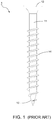
- a conventional screw 1 comprises a shank 11 , a head 12 fitted on the shank 11 , a tapered drilling portion 13 opposite to the head 12 , and a plurality of threads 14 spirally fitted on the shank 11.
- the drilling portion 13 is situated at a surface of a wood board (not shown).
- the head 12 then receives a rotational force in order that the threads 14 is driven by the rotational force to cut the wood board. With the cutting action of the threads 14 , the drilling portion 13 and the shank 11 further thread into the wood board gradually to complete the screwing operation of the screw 1 .
- the disclosed screw 1 still has problems. During the screwing operation, the screw 1 relies on the threads 14 to execute the cutting action of the wood board.
- the wood board is composed of a plurality of elastic wood fibers.
- the threads 14 are unable to serve the wood fibers effectively during the screwing operation. Meanwhile, instead of excluding outwards, the unserved wood fibers accumulate between the threads 14 unduly to further hinder the screwing operation. In addition, some unserved wood fibers entangle around the shank 11 and the drilling portion 13 to result in the increasing drilling resistance. Accordingly, the screwing operation of the screw 1 is not smooth and slowed down.
- EP 2 326 848 B1 discloses a screw having auxiliary threads.
- EP 2 735 746 A1 discloses a screw with a toothed structure.
- the object of this invention is to provide a speedy-screwing screw capable of serving wood fibers effectively to reduce the drilling resistance and attain a quick screwing effect.
- the speedy-screwing screw of this invention comprises a shank, a head fitted at one end of the shank, a drilling portion fitted at another end of the shank and opposite to the head, a plurality of main threads spiraled on the shank, and a plurality of auxiliary threads extending in a second direction opposite to a first direction of the main threads.
- a main diameter of the main threads is larger than an auxiliary diameter of the auxiliary threads.
- Each auxiliary thread has a plurality of cutting sections. Each cutting section has two flank surfaces facing the head and the drilling portion respectively and a crest formed at a junction of the flank surfaces. Adjoining flank surfaces which face the same direction are connected continuously in reverse curves to form the wavelike crests.
- the main threads execute the main cutting action.
- the auxiliary threads push and then break wood fibers of a wood object effectively, thereby providing a dual cutting effect to prevent the shank and the drilling portion from being entangled in wood fibers, and reduce the drilling resistance effectively.
- debris can be excluded outwards through the main threads and the auxiliary threads, thereby preventing the debris from accumulating, preventing the wood object from cracking owing to the accumulated debris, and accelerating the screwing operation greatly.
- At least one of the main threads is provided with at least one slot.
- the auxiliary threads have continuous convolutions spiraling in the second direction.
- each auxiliary thread extends slantingly between two adjoining main threads.
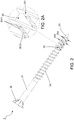
- the speedy-screwing screw 3 includes a shank 31 , a head 32 connected to one side of the shank 31 , a drilling portion 33 formed at another side of the shank 31 and opposite to the head 32 , a plurality of main threads 34 spirally disposed on the shank 31 , and a plurality of auxiliary threads 35 formed on the shank 31 between the main threads 34 and extending toward the drilling portion 33.
- the main threads 34 spirally extend in a first direction.
- the auxiliary threads 35 spirally extend in a second direction which is reverse to the first direction of the main threads 34.
- the main threads 34 are right hand threads.
- the auxiliary threads 35 are left hand threads.
- the auxiliary threads 35 are disposed between the main threads 34 and particularly the auxiliary threads 35 alternate with part of the main threads 34 , as shown in the figures.
- a main diameter 34d of the main threads 34 is larger than an auxiliary diameter 35d of the auxiliary threads 35.
- each of the auxiliary threads 35 may extend slantingly between two adjacent main threads 34 so that the auxiliary threads 35 disconnect from each other.
- the auxiliary threads 35 have continuous convolutions spiraling in the second direction.
- each auxiliary thread 35 includes a plurality of cutting sections 351 connected one after another.
- Each cutting section 351 has two flank surfaces 3511 facing the head 32 and the drilling portion 33 respectively and a crest 3512 formed at a convergence of the two flank surfaces 3511.
- Neighboring flank surfaces 3511 which face the same direction are continuously connected in reverse curves.
- one flank surface 3511 is an upward curve in the middle
- another flank surface 3511 adjoining the one flank surface 3511 is a concave curve in the middle to allow the connected crests 3512 to lie like waves rising and falling.
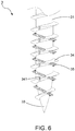
- a screwing operation of the speedy-screwing screw 3 begins with positioning the drilling portion 33 against a surface of a wood object 4. Then, the head 32 receives a rotation force from a driving tool (not shown) in order to carry out the drilling action of the drilling portion 33 and synchronously rotate the main threads 34 to execute the main cutting action of the wood object 4.
- a driving tool not shown
- the auxiliary threads 35 is also driven by the rotation force to assist the drilling portion 33 in reaming the wood object 4 and help the main threads 34 push and then break wood fibers of the wood object 4 effectively, thereby preventing the shank 31 and the drilling portion 33 from being entangled in the wood fibers, reducing the drilling resistance caused by the entanglement of wood fibers.
- the speedy-screwing screw 3 gradually screws into the wood object 4 , debris incurred during the cutting action can be excluded outwards through the main threads 34 and the auxiliary threads 35 , thereby increasing the smoothness of excluding debris.
- the cooperation between the main threads 34 and the auxiliary threads 35 allows the speedy-screwing screw 3 to serve the wood fibers effectively.
- the main threads 34 execute the main cutting action of the wood object 4 , and concurrently the auxiliary threads 35 push and then sever the wood fibers, thereby providing a dual cutting effect to avoid the entanglement of the wood fibers around the shank 31 and the drilling portion 33 , decreasing the drilling resistance incurred during the screwing operation, preventing the wood object 4 from cracking caused by continuously pressing the unduly accumulated debris, and attaining a quick screwing effect.
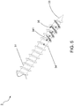
- FIG. 5 shows a second preferred embodiment of the speedy-screwing screw 3 of this invention.
- the correlated elements and the concatenation of elements, the operation and objectives of the second preferred embodiment are the same as those of the first preferred embodiment.
- This embodiment is characterized in that at least one of the main threads 34 is provided with at least one slot 341 which allows the debris incurred during the cutting action to be excluded through the slot 341 smoothly.
- the slot 341 may be formed on the main threads 34 while the auxiliary threads 35 are formed in continuous convolutions.
- the debris can be excluded through not only the main threads 34 and the auxiliary threads 35 , but also the slot 341 , thereby increasing the smoothness of excluding debris, preventing the wood object 4 (not shown) from cracking caused by pressing the accumulated debris, speeding up the screwing operation greatly, and achieving the quick screwing effect.
- the speedy-screwing screw of this invention takes an advantage of the wavelike auxiliary threads which extend in the direction reverse to the direction of the main threads to push and then serve the wood fibers effectively, thereby attaining the dual cutting effect to prevent the drilling portion and the shank from being entangled in the wood fibers, reduce the drilling resistance, accelerate the screwing operation greatly, and achieve the quick screwing effect.
Landscapes
- Engineering & Computer Science (AREA)
- General Engineering & Computer Science (AREA)
- Mechanical Engineering (AREA)
- Physics & Mathematics (AREA)
- Geometry (AREA)
- Life Sciences & Earth Sciences (AREA)
- Chemical & Material Sciences (AREA)
- Dispersion Chemistry (AREA)
- Wood Science & Technology (AREA)
- Connection Of Plates (AREA)
- Joining Of Building Structures In Genera (AREA)
- Drilling Tools (AREA)
Claims (4)
- Vis à vissage rapide (3) comprenant une tige (31), une tête (32) disposée à une extrémité de ladite tige (31), une partie de perçage (33) disposée à une autre extrémité de ladite tige (31) et à l'opposé de ladite tête (32), et une pluralité de filets principaux (34) formés en spirale sur ladite tige (31) et ayant des convolutions de filet principal en spirale dans une première direction ;
caractérisée par le fait qu'une pluralité de filets auxiliaires (35) sont disposés sur ladite tige (31) entre lesdits filets principaux (34) et s'étendent dans la direction de ladite partie de perçage (33), ladite pluralité de filets auxiliaires (35) s'étendant dans une seconde direction qui est l'inverse de ladite première direction de ladite pluralité de filets principaux (34), un diamètre principal (34d) de ladite pluralité de filets principaux (34) étant plus grand qu'un diamètre auxiliaire (35d) de ladite pluralité de filets auxiliaires (35), chacun desdits filets auxiliaires (35) comprenant une pluralité de sections de coupe (351) qui sont reliées les unes à la suite des autres, chacune desdites sections de coupe (351) comprenant deux surfaces de flanc (3511) faisant face à ladite tête (32) et à ladite partie de perçage (33), respectivement, et une crête (3512) formée à une jonction desdites deux surfaces de flanc (3511), les surfaces de flanc adjacentes (3511) qui font face dans une même direction étant reliées de manière continue en courbes inverses pour permettre à ladite pluralité de crêtes (3512) de ressembler à des vagues montantes et descendantes. - Vis à vissage rapide (3) selon la revendication 1, dans laquelle au moins un desdits filets principaux (34) comporte au moins une fente (341).
- Vis à vissage rapide (3) selon la revendication 1 ou 2, dans laquelle lesdits filets auxiliaires (35) ont des convolutions continues en spirale dans la seconde direction.
- Vis à vissage rapide (3) selon la revendication 1 ou 2, dans laquelle chacun desdits filets auxiliaires (35) s'étend de manière inclinée entre deux filets principaux adjacents (34).
Applications Claiming Priority (1)
| Application Number | Priority Date | Filing Date | Title |
|---|---|---|---|
| TW106214051U TWM553763U (zh) | 2017-09-21 | 2017-09-21 | 可快速進給鎖合之螺絲 |
Publications (2)
| Publication Number | Publication Date |
|---|---|
| EP3460263A1 EP3460263A1 (fr) | 2019-03-27 |
| EP3460263B1 true EP3460263B1 (fr) | 2020-03-04 |
Family
ID=61729495
Family Applications (1)
| Application Number | Title | Priority Date | Filing Date |
|---|---|---|---|
| EP18188382.8A Active EP3460263B1 (fr) | 2017-09-21 | 2018-08-10 | Vis à vissage rapide |
Country Status (5)
| Country | Link |
|---|---|
| US (1) | US20190085887A1 (fr) |
| EP (1) | EP3460263B1 (fr) |
| CN (1) | CN208778439U (fr) |
| DK (1) | DK3460263T3 (fr) |
| TW (1) | TWM553763U (fr) |
Families Citing this family (7)
| Publication number | Priority date | Publication date | Assignee | Title |
|---|---|---|---|---|
| PL3822498T3 (pl) * | 2019-11-12 | 2024-07-01 | Bi-Mirth Corp. | Konstrukcja wkrętu do drewna |
| EP3974664B8 (fr) | 2020-09-23 | 2024-01-24 | Bi-Mirth Corp. | Structure de vis à faible usure |
| USD1013498S1 (en) | 2021-02-03 | 2024-02-06 | Illinois Tool Works Inc. | Fastener |
| EP4052672A1 (fr) * | 2021-03-05 | 2022-09-07 | Biedermann Technologies GmbH & Co. KG | Ancrage osseux |
| TWM640656U (zh) * | 2022-12-29 | 2023-05-01 | 何人東 | 省力及防鬆的螺絲 |
| US20250052271A1 (en) * | 2023-08-10 | 2025-02-13 | Integral Building Products Incorporation | Screw structure |
| US20250172168A1 (en) * | 2023-11-29 | 2025-05-29 | Taiwan Shan Yin International Co., Ltd. | Screw |
Family Cites Families (8)
| Publication number | Priority date | Publication date | Assignee | Title |
|---|---|---|---|---|
| US5273383A (en) * | 1991-04-04 | 1993-12-28 | Research Engineering & Manufacturing, Inc. | Threaded fastener for use in thermoplastics and roll die for producing same |
| AT503341B1 (de) * | 2006-02-16 | 2008-02-15 | Schmid Schrauben Hainfeld Ges | Schraube zur verwendung bei verformbaren werkstoffen, wie holz, verbundwerkstoffen und kunststoffen |
| US7862280B2 (en) * | 2006-08-26 | 2011-01-04 | Taiwan Shan Yin International Co., Ltd. | Saw tooth screw |
| US7798756B2 (en) * | 2007-03-24 | 2010-09-21 | Essence Method Refine Co., Ltd. | Screw with waved thread |
| DE102007024240A1 (de) * | 2007-05-18 | 2008-11-20 | Swg Schraubenwerk Gaisbach Gmbh | Schraube |
| DE102008048703A1 (de) * | 2008-09-24 | 2010-03-25 | Fischerwerke Gmbh & Co. Kg | Schraube |
| US8864431B2 (en) * | 2012-03-14 | 2014-10-21 | Taiwan Shan Yin International Co., Ltd. | Screw capable of rapidly drilling and cutting |
| EP2735746A1 (fr) * | 2012-11-23 | 2014-05-28 | Peak Innovation Limited | Vis, ensemble, et méthode de vissage d'une vis dans un objet |
-
2017
- 2017-09-21 TW TW106214051U patent/TWM553763U/zh unknown
-
2018
- 2018-08-09 US US16/059,388 patent/US20190085887A1/en not_active Abandoned
- 2018-08-10 DK DK18188382.8T patent/DK3460263T3/da active
- 2018-08-10 EP EP18188382.8A patent/EP3460263B1/fr active Active
- 2018-08-14 CN CN201821304808.9U patent/CN208778439U/zh active Active
Non-Patent Citations (1)
| Title |
|---|
| None * |
Also Published As
| Publication number | Publication date |
|---|---|
| TWM553763U (zh) | 2018-01-01 |
| DK3460263T3 (da) | 2020-04-06 |
| US20190085887A1 (en) | 2019-03-21 |
| EP3460263A1 (fr) | 2019-03-27 |
| CN208778439U (zh) | 2019-04-23 |
Similar Documents
| Publication | Publication Date | Title |
|---|---|---|
| EP3460263B1 (fr) | Vis à vissage rapide | |
| US7862280B2 (en) | Saw tooth screw | |
| US10801539B2 (en) | Screw capable of reducing drilling torque | |
| US7704030B2 (en) | Screw for use in nonmetal objects | |
| TWI467097B (zh) | 螺釘 | |
| US8348573B2 (en) | Versatile fastener | |
| US20200056647A1 (en) | Fastener | |
| US12215728B2 (en) | Screw | |
| US20190113066A1 (en) | Wood screw | |
| US20250012312A1 (en) | Screw | |
| US20250180057A1 (en) | Screw | |
| US20230048078A1 (en) | Screw with multiple thread angles | |
| EP4134557B1 (fr) | Vis à angles de filetage multiples | |
| EP3550160A1 (fr) | Pièce de fixation | |
| JP6091687B1 (ja) | ねじ | |
| EP1850016B1 (fr) | Vis avec filetage pourvu de dents | |
| EP3508739B1 (fr) | Vis apte à réduire le couple de forage | |
| US11199214B2 (en) | Quick fastening screw | |
| JP2002039134A (ja) | タッピングねじ | |
| EP4488532B1 (fr) | Vis | |
| US20250059998A1 (en) | Fastener | |
| CA2607377C (fr) | Vis pour utilisation dans des objets non metalliques | |
| EP4567288A1 (fr) | Vis | |
| EP4563831B1 (fr) | Vis | |
| JP7752413B2 (ja) | ねじ |
Legal Events
| Date | Code | Title | Description |
|---|---|---|---|
| PUAI | Public reference made under article 153(3) epc to a published international application that has entered the european phase |
Free format text: ORIGINAL CODE: 0009012 |
|
| STAA | Information on the status of an ep patent application or granted ep patent |
Free format text: STATUS: THE APPLICATION HAS BEEN PUBLISHED |
|
| AK | Designated contracting states |
Kind code of ref document: A1 Designated state(s): AL AT BE BG CH CY CZ DE DK EE ES FI FR GB GR HR HU IE IS IT LI LT LU LV MC MK MT NL NO PL PT RO RS SE SI SK SM TR |
|
| AX | Request for extension of the european patent |
Extension state: BA ME |
|
| STAA | Information on the status of an ep patent application or granted ep patent |
Free format text: STATUS: REQUEST FOR EXAMINATION WAS MADE |
|
| 17P | Request for examination filed |
Effective date: 20190611 |
|
| RBV | Designated contracting states (corrected) |
Designated state(s): AL AT BE BG CH CY CZ DE DK EE ES FI FR GB GR HR HU IE IS IT LI LT LU LV MC MK MT NL NO PL PT RO RS SE SI SK SM TR |
|
| GRAP | Despatch of communication of intention to grant a patent |
Free format text: ORIGINAL CODE: EPIDOSNIGR1 |
|
| STAA | Information on the status of an ep patent application or granted ep patent |
Free format text: STATUS: GRANT OF PATENT IS INTENDED |
|
| INTG | Intention to grant announced |
Effective date: 20191007 |
|
| GRAJ | Information related to disapproval of communication of intention to grant by the applicant or resumption of examination proceedings by the epo deleted |
Free format text: ORIGINAL CODE: EPIDOSDIGR1 |
|
| STAA | Information on the status of an ep patent application or granted ep patent |
Free format text: STATUS: REQUEST FOR EXAMINATION WAS MADE |
|
| GRAR | Information related to intention to grant a patent recorded |
Free format text: ORIGINAL CODE: EPIDOSNIGR71 |
|
| GRAS | Grant fee paid |
Free format text: ORIGINAL CODE: EPIDOSNIGR3 |
|
| STAA | Information on the status of an ep patent application or granted ep patent |
Free format text: STATUS: GRANT OF PATENT IS INTENDED |
|
| GRAA | (expected) grant |
Free format text: ORIGINAL CODE: 0009210 |
|
| STAA | Information on the status of an ep patent application or granted ep patent |
Free format text: STATUS: THE PATENT HAS BEEN GRANTED |
|
| INTC | Intention to grant announced (deleted) | ||
| AK | Designated contracting states |
Kind code of ref document: B1 Designated state(s): AL AT BE BG CH CY CZ DE DK EE ES FI FR GB GR HR HU IE IS IT LI LT LU LV MC MK MT NL NO PL PT RO RS SE SI SK SM TR |
|
| INTG | Intention to grant announced |
Effective date: 20200124 |
|
| REG | Reference to a national code |
Ref country code: GB Ref legal event code: FG4D |
|
| REG | Reference to a national code |
Ref country code: CH Ref legal event code: EP |
|
| REG | Reference to a national code |
Ref country code: AT Ref legal event code: REF Ref document number: 1240699 Country of ref document: AT Kind code of ref document: T Effective date: 20200315 |
|
| REG | Reference to a national code |
Ref country code: DE Ref legal event code: R096 Ref document number: 602018002841 Country of ref document: DE |
|
| REG | Reference to a national code |
Ref country code: IE Ref legal event code: FG4D |
|
| REG | Reference to a national code |
Ref country code: DK Ref legal event code: T3 Effective date: 20200403 |
|
| REG | Reference to a national code |
Ref country code: SE Ref legal event code: TRGR |
|
| REG | Reference to a national code |
Ref country code: NO Ref legal event code: T2 Effective date: 20200304 |
|
| PG25 | Lapsed in a contracting state [announced via postgrant information from national office to epo] |
Ref country code: FI Free format text: LAPSE BECAUSE OF FAILURE TO SUBMIT A TRANSLATION OF THE DESCRIPTION OR TO PAY THE FEE WITHIN THE PRESCRIBED TIME-LIMIT Effective date: 20200304 Ref country code: RS Free format text: LAPSE BECAUSE OF FAILURE TO SUBMIT A TRANSLATION OF THE DESCRIPTION OR TO PAY THE FEE WITHIN THE PRESCRIBED TIME-LIMIT Effective date: 20200304 |
|
| PGFP | Annual fee paid to national office [announced via postgrant information from national office to epo] |
Ref country code: NO Payment date: 20200619 Year of fee payment: 3 |
|
| REG | Reference to a national code |
Ref country code: NL Ref legal event code: MP Effective date: 20200304 |
|
| PG25 | Lapsed in a contracting state [announced via postgrant information from national office to epo] |
Ref country code: BG Free format text: LAPSE BECAUSE OF FAILURE TO SUBMIT A TRANSLATION OF THE DESCRIPTION OR TO PAY THE FEE WITHIN THE PRESCRIBED TIME-LIMIT Effective date: 20200604 Ref country code: LV Free format text: LAPSE BECAUSE OF FAILURE TO SUBMIT A TRANSLATION OF THE DESCRIPTION OR TO PAY THE FEE WITHIN THE PRESCRIBED TIME-LIMIT Effective date: 20200304 Ref country code: GR Free format text: LAPSE BECAUSE OF FAILURE TO SUBMIT A TRANSLATION OF THE DESCRIPTION OR TO PAY THE FEE WITHIN THE PRESCRIBED TIME-LIMIT Effective date: 20200605 Ref country code: HR Free format text: LAPSE BECAUSE OF FAILURE TO SUBMIT A TRANSLATION OF THE DESCRIPTION OR TO PAY THE FEE WITHIN THE PRESCRIBED TIME-LIMIT Effective date: 20200304 |
|
| REG | Reference to a national code |
Ref country code: LT Ref legal event code: MG4D |
|
| PG25 | Lapsed in a contracting state [announced via postgrant information from national office to epo] |
Ref country code: NL Free format text: LAPSE BECAUSE OF FAILURE TO SUBMIT A TRANSLATION OF THE DESCRIPTION OR TO PAY THE FEE WITHIN THE PRESCRIBED TIME-LIMIT Effective date: 20200304 |
|
| PG25 | Lapsed in a contracting state [announced via postgrant information from national office to epo] |
Ref country code: ES Free format text: LAPSE BECAUSE OF FAILURE TO SUBMIT A TRANSLATION OF THE DESCRIPTION OR TO PAY THE FEE WITHIN THE PRESCRIBED TIME-LIMIT Effective date: 20200304 Ref country code: PT Free format text: LAPSE BECAUSE OF FAILURE TO SUBMIT A TRANSLATION OF THE DESCRIPTION OR TO PAY THE FEE WITHIN THE PRESCRIBED TIME-LIMIT Effective date: 20200729 Ref country code: IS Free format text: LAPSE BECAUSE OF FAILURE TO SUBMIT A TRANSLATION OF THE DESCRIPTION OR TO PAY THE FEE WITHIN THE PRESCRIBED TIME-LIMIT Effective date: 20200704 Ref country code: SK Free format text: LAPSE BECAUSE OF FAILURE TO SUBMIT A TRANSLATION OF THE DESCRIPTION OR TO PAY THE FEE WITHIN THE PRESCRIBED TIME-LIMIT Effective date: 20200304 Ref country code: SM Free format text: LAPSE BECAUSE OF FAILURE TO SUBMIT A TRANSLATION OF THE DESCRIPTION OR TO PAY THE FEE WITHIN THE PRESCRIBED TIME-LIMIT Effective date: 20200304 Ref country code: EE Free format text: LAPSE BECAUSE OF FAILURE TO SUBMIT A TRANSLATION OF THE DESCRIPTION OR TO PAY THE FEE WITHIN THE PRESCRIBED TIME-LIMIT Effective date: 20200304 Ref country code: RO Free format text: LAPSE BECAUSE OF FAILURE TO SUBMIT A TRANSLATION OF THE DESCRIPTION OR TO PAY THE FEE WITHIN THE PRESCRIBED TIME-LIMIT Effective date: 20200304 Ref country code: CZ Free format text: LAPSE BECAUSE OF FAILURE TO SUBMIT A TRANSLATION OF THE DESCRIPTION OR TO PAY THE FEE WITHIN THE PRESCRIBED TIME-LIMIT Effective date: 20200304 Ref country code: LT Free format text: LAPSE BECAUSE OF FAILURE TO SUBMIT A TRANSLATION OF THE DESCRIPTION OR TO PAY THE FEE WITHIN THE PRESCRIBED TIME-LIMIT Effective date: 20200304 |
|
| PGFP | Annual fee paid to national office [announced via postgrant information from national office to epo] |
Ref country code: DE Payment date: 20200826 Year of fee payment: 3 Ref country code: DK Payment date: 20200709 Year of fee payment: 3 Ref country code: FR Payment date: 20200826 Year of fee payment: 3 |
|
| REG | Reference to a national code |
Ref country code: AT Ref legal event code: MK05 Ref document number: 1240699 Country of ref document: AT Kind code of ref document: T Effective date: 20200304 |
|
| PGFP | Annual fee paid to national office [announced via postgrant information from national office to epo] |
Ref country code: SE Payment date: 20200813 Year of fee payment: 3 |
|
| REG | Reference to a national code |
Ref country code: DE Ref legal event code: R097 Ref document number: 602018002841 Country of ref document: DE |
|
| PLBE | No opposition filed within time limit |
Free format text: ORIGINAL CODE: 0009261 |
|
| STAA | Information on the status of an ep patent application or granted ep patent |
Free format text: STATUS: NO OPPOSITION FILED WITHIN TIME LIMIT |
|
| PG25 | Lapsed in a contracting state [announced via postgrant information from national office to epo] |
Ref country code: IT Free format text: LAPSE BECAUSE OF FAILURE TO SUBMIT A TRANSLATION OF THE DESCRIPTION OR TO PAY THE FEE WITHIN THE PRESCRIBED TIME-LIMIT Effective date: 20200304 Ref country code: AT Free format text: LAPSE BECAUSE OF FAILURE TO SUBMIT A TRANSLATION OF THE DESCRIPTION OR TO PAY THE FEE WITHIN THE PRESCRIBED TIME-LIMIT Effective date: 20200304 |
|
| 26N | No opposition filed |
Effective date: 20201207 |
|
| PG25 | Lapsed in a contracting state [announced via postgrant information from national office to epo] |
Ref country code: SI Free format text: LAPSE BECAUSE OF FAILURE TO SUBMIT A TRANSLATION OF THE DESCRIPTION OR TO PAY THE FEE WITHIN THE PRESCRIBED TIME-LIMIT Effective date: 20200304 Ref country code: PL Free format text: LAPSE BECAUSE OF FAILURE TO SUBMIT A TRANSLATION OF THE DESCRIPTION OR TO PAY THE FEE WITHIN THE PRESCRIBED TIME-LIMIT Effective date: 20200304 |
|
| PG25 | Lapsed in a contracting state [announced via postgrant information from national office to epo] |
Ref country code: MC Free format text: LAPSE BECAUSE OF FAILURE TO SUBMIT A TRANSLATION OF THE DESCRIPTION OR TO PAY THE FEE WITHIN THE PRESCRIBED TIME-LIMIT Effective date: 20200304 |
|
| PG25 | Lapsed in a contracting state [announced via postgrant information from national office to epo] |
Ref country code: LU Free format text: LAPSE BECAUSE OF NON-PAYMENT OF DUE FEES Effective date: 20200810 |
|
| REG | Reference to a national code |
Ref country code: BE Ref legal event code: MM Effective date: 20200831 |
|
| PG25 | Lapsed in a contracting state [announced via postgrant information from national office to epo] |
Ref country code: IE Free format text: LAPSE BECAUSE OF NON-PAYMENT OF DUE FEES Effective date: 20200810 Ref country code: BE Free format text: LAPSE BECAUSE OF NON-PAYMENT OF DUE FEES Effective date: 20200831 |
|
| REG | Reference to a national code |
Ref country code: DE Ref legal event code: R119 Ref document number: 602018002841 Country of ref document: DE |
|
| REG | Reference to a national code |
Ref country code: DK Ref legal event code: EBP Effective date: 20210831 |
|
| REG | Reference to a national code |
Ref country code: NO Ref legal event code: MMEP |
|
| REG | Reference to a national code |
Ref country code: SE Ref legal event code: EUG |
|
| REG | Reference to a national code |
Ref country code: CH Ref legal event code: PL |
|
| PG25 | Lapsed in a contracting state [announced via postgrant information from national office to epo] |
Ref country code: LI Free format text: LAPSE BECAUSE OF NON-PAYMENT OF DUE FEES Effective date: 20210831 Ref country code: CH Free format text: LAPSE BECAUSE OF NON-PAYMENT OF DUE FEES Effective date: 20210831 |
|
| PG25 | Lapsed in a contracting state [announced via postgrant information from national office to epo] |
Ref country code: TR Free format text: LAPSE BECAUSE OF FAILURE TO SUBMIT A TRANSLATION OF THE DESCRIPTION OR TO PAY THE FEE WITHIN THE PRESCRIBED TIME-LIMIT Effective date: 20200304 Ref country code: SE Free format text: LAPSE BECAUSE OF NON-PAYMENT OF DUE FEES Effective date: 20210811 Ref country code: NO Free format text: LAPSE BECAUSE OF NON-PAYMENT OF DUE FEES Effective date: 20210831 Ref country code: MT Free format text: LAPSE BECAUSE OF FAILURE TO SUBMIT A TRANSLATION OF THE DESCRIPTION OR TO PAY THE FEE WITHIN THE PRESCRIBED TIME-LIMIT Effective date: 20200304 Ref country code: CY Free format text: LAPSE BECAUSE OF FAILURE TO SUBMIT A TRANSLATION OF THE DESCRIPTION OR TO PAY THE FEE WITHIN THE PRESCRIBED TIME-LIMIT Effective date: 20200304 |
|
| PG25 | Lapsed in a contracting state [announced via postgrant information from national office to epo] |
Ref country code: MK Free format text: LAPSE BECAUSE OF FAILURE TO SUBMIT A TRANSLATION OF THE DESCRIPTION OR TO PAY THE FEE WITHIN THE PRESCRIBED TIME-LIMIT Effective date: 20200304 Ref country code: AL Free format text: LAPSE BECAUSE OF FAILURE TO SUBMIT A TRANSLATION OF THE DESCRIPTION OR TO PAY THE FEE WITHIN THE PRESCRIBED TIME-LIMIT Effective date: 20200304 |
|
| PG25 | Lapsed in a contracting state [announced via postgrant information from national office to epo] |
Ref country code: FR Free format text: LAPSE BECAUSE OF NON-PAYMENT OF DUE FEES Effective date: 20210831 Ref country code: DK Free format text: LAPSE BECAUSE OF NON-PAYMENT OF DUE FEES Effective date: 20210831 Ref country code: DE Free format text: LAPSE BECAUSE OF NON-PAYMENT OF DUE FEES Effective date: 20220301 |
|
| GBPC | Gb: european patent ceased through non-payment of renewal fee |
Effective date: 20220810 |
|
| PG25 | Lapsed in a contracting state [announced via postgrant information from national office to epo] |
Ref country code: GB Free format text: LAPSE BECAUSE OF NON-PAYMENT OF DUE FEES Effective date: 20220810 |