EP3460346A1 - Klimaanlage - Google Patents
Klimaanlage Download PDFInfo
- Publication number
- EP3460346A1 EP3460346A1 EP16902360.3A EP16902360A EP3460346A1 EP 3460346 A1 EP3460346 A1 EP 3460346A1 EP 16902360 A EP16902360 A EP 16902360A EP 3460346 A1 EP3460346 A1 EP 3460346A1
- Authority
- EP
- European Patent Office
- Prior art keywords
- refrigerant
- refrigerant sensor
- floor
- unit
- control board
- Prior art date
- Legal status (The legal status is an assumption and is not a legal conclusion. Google has not performed a legal analysis and makes no representation as to the accuracy of the status listed.)
- Withdrawn
Links
Images


Classifications
-
- F—MECHANICAL ENGINEERING; LIGHTING; HEATING; WEAPONS; BLASTING
- F25—REFRIGERATION OR COOLING; COMBINED HEATING AND REFRIGERATION SYSTEMS; HEAT PUMP SYSTEMS; MANUFACTURE OR STORAGE OF ICE; LIQUEFACTION SOLIDIFICATION OF GASES
- F25B—REFRIGERATION MACHINES, PLANTS OR SYSTEMS; COMBINED HEATING AND REFRIGERATION SYSTEMS; HEAT PUMP SYSTEMS
- F25B49/00—Arrangement or mounting of control or safety devices
- F25B49/005—Arrangement or mounting of control or safety devices of safety devices
-
- F—MECHANICAL ENGINEERING; LIGHTING; HEATING; WEAPONS; BLASTING
- F25—REFRIGERATION OR COOLING; COMBINED HEATING AND REFRIGERATION SYSTEMS; HEAT PUMP SYSTEMS; MANUFACTURE OR STORAGE OF ICE; LIQUEFACTION SOLIDIFICATION OF GASES
- F25B—REFRIGERATION MACHINES, PLANTS OR SYSTEMS; COMBINED HEATING AND REFRIGERATION SYSTEMS; HEAT PUMP SYSTEMS
- F25B49/00—Arrangement or mounting of control or safety devices
- F25B49/02—Arrangement or mounting of control or safety devices for compression type machines, plants or systems
-
- F—MECHANICAL ENGINEERING; LIGHTING; HEATING; WEAPONS; BLASTING
- F24—HEATING; RANGES; VENTILATING
- F24F—AIR-CONDITIONING; AIR-HUMIDIFICATION; VENTILATION; USE OF AIR CURRENTS FOR SCREENING
- F24F11/00—Control or safety arrangements
- F24F11/89—Arrangement or mounting of control or safety devices
-
- F—MECHANICAL ENGINEERING; LIGHTING; HEATING; WEAPONS; BLASTING
- F25—REFRIGERATION OR COOLING; COMBINED HEATING AND REFRIGERATION SYSTEMS; HEAT PUMP SYSTEMS; MANUFACTURE OR STORAGE OF ICE; LIQUEFACTION SOLIDIFICATION OF GASES
- F25B—REFRIGERATION MACHINES, PLANTS OR SYSTEMS; COMBINED HEATING AND REFRIGERATION SYSTEMS; HEAT PUMP SYSTEMS
- F25B2400/00—Component parts or details not otherwise provided for in this subclass
- F25B2400/12—Inflammable refrigerants
-
- F—MECHANICAL ENGINEERING; LIGHTING; HEATING; WEAPONS; BLASTING
- F25—REFRIGERATION OR COOLING; COMBINED HEATING AND REFRIGERATION SYSTEMS; HEAT PUMP SYSTEMS; MANUFACTURE OR STORAGE OF ICE; LIQUEFACTION SOLIDIFICATION OF GASES
- F25B—REFRIGERATION MACHINES, PLANTS OR SYSTEMS; COMBINED HEATING AND REFRIGERATION SYSTEMS; HEAT PUMP SYSTEMS
- F25B2500/00—Problems to be solved
- F25B2500/22—Preventing, detecting or repairing leaks of refrigeration fluids
- F25B2500/222—Detecting refrigerant leaks
Definitions
- the present invention relates to an air conditioner that includes a floor-mounted type indoor unit and a refrigerant sensor that detects a refrigerant leak occurring on a floor-mounted type indoor unit side.
- Fluorocarbon-based refrigerants are stable and easy to handle but have high global warming potentials, adversely affecting the global environment; thus, hydrocarbon-based refrigerants such as propane and propylene, which are natural refrigerants having low warming potentials, have become a focus of attention as a replacement of the fluorocarbon-based refrigerants.
- hydrocarbon-based refrigerants which are flammable
- a refrigerant leak from the air conditioner may achieve a flammable concentration. It is thus desirable that an air conditioner have a measure to detect a refrigerant leak at an early stage and prevent the refrigerant leak from achieving the flammable concentration.
- a floor-mounted type indoor unit disclosed in Patent Literature 1 includes a control board that provides centralized control over devices such as an air fan, a fan motor, and a compressor, and a remote controller, for a user to operate an air conditioner, that monitors an operation state and an anomaly description.
- a refrigerant sensor is connected to the control board via wiring including a signal wire.
- the refrigerant sensor is placed below a machine chamber in the floor-mounted type indoor unit disclosed in Patent Literature 1.
- the refrigerant sensor is placed in this manner for the following reasons.
- the refrigerant sensor which is placed in this manner, detects a refrigerant leak from a component that configures a refrigeration cycle, such as a heat exchanger and a union joint, and, when the concentration of the leak reaches a certain value or greater, the floor-mounted type indoor unit operates the air fan to diffuse the refrigerant leak, thereby preventing the concentration of the refrigerant leak from achieving a flammable concentration.
- a component that configures a refrigeration cycle such as a heat exchanger and a union joint
- Patent Literature 1 Japanese Patent Application Laid-open No. 2015-94566
- the floor-mounted type indoor unit disclosed in Patent Literature 1 needs a measure on the refrigerant sensor to prevent spread of fire, posing a problem of costs incurred for the prevention of spread of fire.
- the present invention has been achieved in view of the above, and an object of the present invention is to provide an air conditioner that can detect a refrigerant leak and reduce costs for preventing spread of fire.
- an air conditioner includes: a floor-mounted type indoor unit; a control board, placed in the floor-mounted type indoor unit, that controls the floor-mounted type indoor unit; a refrigerant sensor, placed in the floor-mounted type indoor unit, that outputs a detection signal that has on-duty varied in accordance with a detected refrigerant concentration; and a current limitation unit, placed in the floor-mounted type indoor unit, that limits a current supplied to the refrigerant sensor when a short-circuit failure occurs in the refrigerant sensor.
- An air conditioner according to the present invention produces effects of enabling detection of a refrigerant leak and reduction of costs for preventing spread of fire.
- FIG. 1 is an exterior view of an air conditioner according to an embodiment of the present invention.
- An air conditioner 100 includes an outdoor unit 1, a floor-mounted type indoor unit 2 connected to the outdoor unit 1, and piping 3 connecting the outdoor unit 1 to the floor-mounted type indoor unit 2 and allowing a refrigerant to flow therethrough.
- the air conditioner 100 according to the present embodiment uses a flammable hydrocarbon-based refrigerant.
- the floor-mounted type indoor unit 2 includes a housing 20, a front panel 21 placed on a front of the housing 20, and a remote controller 22.
- the remote controller 22 may be simply referred to as "remote controller 22" below.
- the housing 20 is a hollow box body and has a front opening portion in a front face of the housing 20.
- the front panel 21 is detachably attached to the front opening portion of the housing 20.
- the front panel 21 has an air inlet port 21a formed in a lower side of the front panel 21 and an air outlet port 21b formed in an upper side of the front panel 21.
- the front panel 21 includes the remote controller 22 between the air inlet port 21a and the air outlet port 21b.
- the remote controller 22 is a user interface that allows a user to operate the air conditioner 100 and monitor an operation state and an anomaly description of the air conditioner 100. Examples of operating can include an operation to start the air conditioner 100, an operation to stop the air conditioner 100, and an operation to switch operation modes. Examples of anomaly descriptions can include refrigerant leak information indicating a refrigerant leak from a component configuring a refrigeration cycle of the air conditioner 100, communication anomaly information indicating an anomaly in communication between the floor-mounted type indoor unit 2 and the outdoor unit 1, and disconnection anomaly information indicating a disconnection in a signal wire connected to a refrigerant sensor.
- the remote controller 22 includes a display unit 22a that displays the operation state and the anomaly descriptions.
- the refrigerant leak information which has higher priority over other information such as the communication anomaly information and the disconnection anomaly information, is displayed on the display unit 22a of the remote controller 22. This notifies a user of a refrigerant leak before the refrigerant leak achieves the flammable concentration, thereby encouraging the user to ventilate a room in which the air conditioner 100 is installed or to operate the air conditioner 100 to force the refrigerant leak to diffuse.
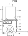
- FIG. 2 is an interior view of the floor-mounted type indoor unit illustrated in FIG. 1 .
- the housing 20 of the floor-mounted type indoor unit 2 illustrated in FIG. 2 has a lower space 200 that configures an air intake portion and an upper space 201 that is located above the lower space 200 and configures a heat exchange portion.
- the lower space 200 and the upper space 201 are divided by a partition portion 4.
- the partition portion 4 has a flat plate shape and placed in the middle of the housing 20 in an up-and-down direction.
- the partition portion 4 has an air-path opening portion 4a that provides an air path between the lower space 200 and the upper space 201.
- the lower space 200 is placed on a back face side of the air inlet port 21a illustrated in FIG. 1 and exposed to a front face side when the air inlet port 21a is removed from the front panel 21.
- the upper space 201 is placed on a back face side of the air outlet port 21b illustrated in FIG. 1 and exposed to a front face side when the air outlet port 21b is removed from the front panel 21.
- An indoor air fan 5 that generates an air flow from the air inlet port 21a toward the air outlet port 21b illustrated in FIG. 1 is placed in the lower space 200.
- the indoor air fan 5 is a sirocco fan that is connected to an output shaft 5b of a motor 5a and has an impeller 5c having a plurality of blades placed in a circumferential direction at regular intervals.
- the indoor air fan 5 is covered by a fan casing 6 having a scroll shape.
- the fan casing 6 is placed in a location facing the air inlet port 21a illustrated in FIG. 1 . Since the fan casing 6 is placed below the partition portion 4, the inside of the fan casing 6 is a part of the lower space 200.
- a refrigerant sensor 7 that detects a refrigerant leak and an electrical-item box 8 having a cuboid shape are also placed in the lower space 200.
- the electrical-item box 8 is placed above the indoor air fan 5 and houses a control board 9 that controls the floor-mounted type indoor unit 2, and a relay board 10 internally.
- the control board 9 has a drive control function with which centralized control is provided over units to be controlled that configure the air conditioner 100 and an anomaly display function with which an anomaly description for an anomaly that has occurred in the air conditioner 100 is displayed on the display unit 22a of the remote controller 22 illustrated in FIG. 1 .
- the units to be controlled include undepicted devices such as fan motors, air direction plates, compressors, and propeller fans mounted in the floor-mounted type indoor unit 2 and in the outdoor unit 1.
- Examples of the anomaly description on the anomaly display function can include the refrigerant leak information, which indicates a refrigerant leak, the communication anomaly information, which indicates an anomaly in the communication between the floor-mounted type indoor unit 2 and the outdoor unit 1, the disconnection anomaly information, which indicates a disconnection in wiring 7a, and short-circuit failure information that indicates a short circuit in the refrigerant sensor 7.
- the refrigerant sensor 7 includes the wiring 7a for transmitting, to the control board 9, a detection signal 71 that is output by the refrigerant sensor 7, and the wiring 7a is connected to the relay board 10.
- the refrigerant sensor 7 is placed below the indoor air fan 5 and detects the concentration of the refrigerant in the air surrounding the refrigerant sensor 7.
- the refrigerant sensor 7 outputs the detection signal 71, which has on-duty varied in accordance with the detected refrigerant concentration. A configuration of the refrigerant sensor 7 is described in detail below.
- the upper space 201 is located downstream of the lower space 200 in terms of the air flow generated by the indoor air fan 5.
- An indoor heat exchanger 11 is placed in the upper space 201.
- the indoor heat exchanger 11 is connected to one end of an indoor piping 11a that allows the refrigerant to pass therethrough, and a joint unit 12a is connected to the other end of the indoor piping 11a.
- the indoor piping 11a passes through the partition portion 4, and the joint unit 12a is placed in the lower space 200.
- a joint unit 12b is placed on one end of the piping 3, which is extended piping.
- the piping 3 and the indoor piping 11a are connected together by connecting the joint unit 12b to the joint unit 12a.
- Possible refrigerant leak locations in the floor-mounted type indoor unit 2, which is configured as described above, are a brazed portion 13 between the indoor heat exchanger 11 and the indoor piping 11a and a connected portion 14 between the joint unit 12a and the joint unit 12b.
- the refrigerant used in the air conditioner 100 according to the present embodiment is a flammable refrigerant having specific gravity greater than that of air.
- a refrigerant leak from at least one of the brazed portion 13 and the connected portion 14 thus leads to an increased concentration of the refrigerant in the lower space 200. Locating the refrigerant sensor 7 in a lower portion of the lower space 200 enables accurate measurement of the concentration of the refrigerant that is collected on a bottom surface of the lower space 200.
- the detection signal 71 which is output by the refrigerant sensor 7, is received by the control board 9 via the wiring 7a and the relay board 10.
- the control board 9 operates the indoor air fan 5 to diffuse a refrigerant leak when the concentration of the leaking refrigerant reaches a certain value or greater on the basis of the detection signal 71, which is output by the refrigerant sensor 7, thus preventing the concentration of the refrigerant leak from reaching the flammable concentration.
- the refrigerant sensor needs to be covered in a metal housing similar to that used for the control board or in flame-retardant resin as a measure taken on the refrigerant sensor to prevent spread of fire.
- the air conditioner 100 does not have such measures taken on the refrigerant sensor 7 and includes a current limitation unit for limiting a current supplied to the refrigerant sensor 7 when a short-circuit failure occurs in the refrigerant sensor 7, thereby preventing spread of fire.
- a current limitation unit for limiting a current supplied to the refrigerant sensor 7 when a short-circuit failure occurs in the refrigerant sensor 7, thereby preventing spread of fire.
- FIG. 3 is a diagram illustrating the remote controller, the control board, the relay board, and the refrigerant sensor included in the air conditioner according to the embodiment of the present invention in a connected state.
- the remote controller 22 is connected to wiring 22b that includes a connector 22c.
- the control board 9 includes a control unit 9a, a connecting terminal 9b, a connecting terminal 9c, and a power source 9d for supplying power to the relay board 10 and the refrigerant sensor 7.
- the control board 9 includes a communication line 9e for transmitting, to the control unit 9a, a feedback signal output by a current limitation unit 10a included in the relay board 10, and a signal wire 9f for transmitting, to the control unit 9a, the detection signal 71, which is output by the refrigerant sensor 7.
- the control unit 9a has the drive control function and the anomaly display function described above.
- the remote controller 22 is connected to the control unit 9a by connecting the connecting terminal 9c to the connector 22c of the remote controller 22.
- the power source 9d is connected to the connecting terminal 9b.
- the communication line 9e has one end connected to the control unit 9a and the other end connected to the connecting terminal 9b.
- the signal wire 9f has one end connected to the control unit 9a and the other end connected to the connecting terminal 9b.
- the relay board 10 includes the current limitation unit 10a, which limits a current supplied to the refrigerant sensor 7 to inhibit an excessive current from flowing through the refrigerant sensor 7 when a short-circuit failure occurs in the refrigerant sensor 7.
- the relay board 10 also includes a connecting terminal 10b, a connecting terminal 10c, a power line 10d1 connected to the connecting terminal 10c, a power line 10d2 connected to the connecting terminal 10b, a communication line 10e connected to the connecting terminal 10c, and a signal wire 10f for transmitting the detection signal 71, which is output by the refrigerant sensor 7, to the control unit 9a.
- the control board 9 is connected to the relay board 10 by wiring 16.
- the wiring 16 includes a power line, a communication line, and a signal wire, and a connector 16a placed on one end side of the wiring 16 is connected to the connecting terminal 9b of the control board 9.
- a connector 16b placed on the other end side of the wiring 16 is connected to the connecting terminal 10c of the relay board 10.
- the power source 9d of the control board 9 is supplied to the current limitation unit 10a via the power line 10d1 by connecting the connector 16a of the wiring 16 to the connecting terminal 9b.
- the refrigerant sensor 7 includes the wiring 7a, a connector 7b connected to one end of the wiring 7a, a connector 7c connected to the other end of the wiring 7a, a refrigerant detection circuit 7d, a power source 7e having the same electric potential as the power source 9d, and a signal wire 7f.
- the wiring 7a includes a power line, a communication line, and a signal wire.
- the power source 9d of the control board 9 is supplied to the refrigerant sensor 7 via the current limitation unit 10a by connecting the connector 7b to the connecting terminal 10b of the relay board 10 and connecting the connector 7b to the connecting terminal 10b.
- the detection signal 71 which is output by the refrigerant detection circuit 7d, is transmitted to the control unit 9a via the signal wire 7f, the signal wire 10f of the relay board 10, and the signal wire 9f of the control board 9.
- the refrigerant detection circuit 7d includes a transistor 402 for varying electric potentials of the signal wire 7f, the signal wire 10f, and the signal wire 9f, a sensor element 403 for detecting a refrigerant, and a control unit 404 that controls on/off timing of the transistor 402 in accordance with the concentration of the refrigerant detected by the sensor element 403.
- the power source 7e which is needed for operations of the transistor 402 and the refrigerant detection circuit 7d, is supplied from the control board 9. While the transistor 402 is used in the refrigerant detection circuit 7d, a switch element, such as an operational amplifier or a relay, may be used in place of the transistor 402.
- FIG. 4 is a configuration diagram of the current limitation unit illustrated in FIG. 3 .
- the current limitation unit 10a illustrated in FIG. 4 includes a resistor 302 having one end connected to a power source 301, and a transistor 303 having a drain connected to the other end of the resistor 302.
- the current limitation unit 10a also includes a comparator 304 that compares an electric potential at an end connection between the resistor 302 and the transistor 303 to an electric potential of the power source 301 and outputs a comparison result in a digital value of one or zero.
- the current limitation unit 10a also includes a power source terminal 305 connected to an end connection between the resistor 302 and the drain of the transistor 303 and connected to the power line 10d2, and a communication terminal 306 connected to an output end of the comparator 304 and connected to the communication line 10e.
- control board 9 Operations of the control board 9, the relay board 10, and the refrigerant sensor 7 are described below.
- the current limitation unit 10a When the operation of the refrigerant sensor 7 is in a normal state, the current limitation unit 10a operates in such a manner that a current loss is very small; thus, a current of the power source 9d is supplied to the refrigerant sensor 7 with a voltage of the power source 9d unvaried. Additionally, when the operation of the refrigerant sensor 7 is in the normal state, the feedback signal, which is output by the current limitation unit 10a, is transmitted to the control unit 9a of the control board 9.
- the feedback signal that is output by the current limitation unit 10a in this case is a signal at an L level output by the comparator 304.
- the current having a value lower than the certain value here is a current having a value lower than that of a current that can cause the refrigerant sensor 7 to undergo heating and spread fire due to the short-circuit failure; the current having a value lower than the certain value may be a current having a value that does not allow the refrigerant sensor 7 to continue operating.
- the signal at the L level that is transmitted to the communication terminal 306 is transmitted to the communication line 10e, which is connected to the communication terminal 306, and to the control unit 9a as the feedback signal.
- the feedback signal at the L level that is transmitted to the control unit 9a is a signal that indicates occurrence of the short-circuit failure in the refrigerant sensor 7.
- a gate of the transistor 303 changes from on to off due to the change in the output of the comparator 304 from the H level to the L level. This limits a current supplied to the power source terminal 305 to a value lower than the certain value.
- the current limitation unit 10a may use an operational amplifier in place of the comparator 304. When an operational amplifier is used in place of the comparator 304, a current flowing through the power line 10d2 can be varied linearly.
- the sensor element 403 or the control unit 404 of the refrigerant detection circuit 7d can be prevented from being heated by an excessive current in this manner. Additionally, the control unit 9a of the control board 9 causes the remote controller 22 to display the short-circuit failure information described above when the control unit 9a detects the short-circuit failure in the refrigerant sensor 7 based on the feedback signal, which is output by the current limitation unit 10a.
- Examples of a method to display the short-circuit failure information on the remote controller 22 can include a method of displaying message information indicative of occurrence of the short-circuit failure on the display unit 22a of the remote controller 22 and a method of causing a light emitting diode (LED) that is an undepicted light emitting unit included in the remote controller 22 to turn on when the refrigerant sensor 7 is in the normal state and to flash when the short-circuit failure occurs in the refrigerant sensor 7.
- LED light emitting diode
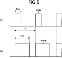
- FIG. 5 is a diagram illustrating an example pulse-width modulating signal output by the control unit of the refrigerant sensor illustrated in FIG. 3 .
- a pulse-width modulating signal 404a that is output by the control unit 404 when the concentration of the refrigerant detected by the sensor element 403 is smaller than a certain value is illustrated.
- on-duty which is a ratio of an on-time Ton to a cycle T of the pulse-width modulating signal 404a is 30%.
- the pulse-width modulating signal 404a that is output by the control unit 404 when the concentration of the refrigerant detected by the sensor element 403 is equal to or greater than the certain value is illustrated.
- the on-duty is 70%.
- the control unit 404 generates the pulse-width modulating signal 404a, which increases the on-duty as the concentration of the refrigerant detected by the sensor element 403 increases as described above.
- Examples of the sensor element 403 can include a thermistor that varies a resistance value using cooling effect of the refrigerant. Specifically, the resistance value of the thermistor decreases as the concentration of the refrigerant increases, increasing a current value input to the control unit 404 from the power source 7e. The control unit 404 varies the on-duty of the pulse-width modulating signal 404a as illustrated in FIG. 5 on the basis of the magnitude of the value of the current.
- the power source 7e which is needed for the operations of the transistor 402 and the refrigerant detection circuit 7d of the refrigerant sensor 7, is supplied from the control board 9, and the on-duty of the pulse-width modulating signal 404a is varied in accordance with the concentration of the refrigerant detected by the sensor element 403.
- the transistor 402 is controlled in this manner, changing an electric potential applied to the signal wire 7f, which is connected to a collector of the transistor 402. That is, the on-duty of the detection signal 71 varies with the concentration of the refrigerant.
- the control unit 9a of the control board 9 can determine whether the concentration of the refrigerant is equal to or greater than the certain value or smaller than the certain value by measuring the on-duty of the detection signal 71. That is, the control unit 9a determines that there is no refrigerant leak when receiving the detection signal 71 that has short on-duty as illustrated in FIG. 5(1) and does not cause the remote controller 22 to display the refrigerant leak information; the control unit 9a determines that there is a refrigerant leak when receiving the detection signal 71 that has long on-duty illustrated in FIG. 5(2) and causes the remote controller 22 to display the refrigerant leak information, which has higher priority over other information such as communication anomaly and disconnection anomaly.
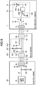
- FIG. 6 is a diagram illustrating modifications of the control board and the relay board illustrated in FIG. 3 . Differences between the control board 9 and the relay board 10 illustrated in FIG. 3 and a control board 9A and a relay board 10A illustrated in FIG. 6 , respectively, are as follows.
- Use of the current limitation unit 10a-1 eliminates the need to receive the feedback signal, which indicates occurrence of a short-circuit failure in the refrigerant sensor 7.
- the communication line 9e and the communication line 10e illustrated in FIG. 3 are thus no longer necessary, which results in simplified structures of the control board 9A and the relay board 10A and thereby improves yield and reliability. Operations of the control board 9A, the relay board 10A, and the refrigerant sensor 7 are described below.
- the control unit 9a of the control board 9A determines whether the concentration of a refrigerant is equal to or greater than a certain value or smaller than the certain value by measuring the on-duty of the detection signal 71.
- the transistor 402 is turned on, a voltage output from the power source 9d is divided due to the resistor 9g, the resistor 308, and on-resistance of the transistor 402. A resultant divided voltage is applied to the control unit 9a of the control board 9A.
- the control unit 9a can clearly distinguish an electric potential of the signal wire observed when the transistor 402 is turned on from an electric potential of the signal wire observed when the transistor 402 is turned off. This allows the control unit 9a to determine whether the concentration of the refrigerant is equal to or greater than the certain value or smaller than the certain value by measuring the on-duty of the detection signal 71.
- a case in which a short-circuit failure occurs in the refrigerant sensor 7 and causes an overcurrent to flow is described next.
- the control board 9A attempts to continue causing a current to flow until the supply capacity of the power source 9d is reached. If, however, a current having a value greater than a certain value flows, the fuse 307 in the current limitation unit 10a-1 melts, interrupting the flow of the current.
- the refrigerant sensor 7 causes the refrigerant sensor 7 to lose a power source, with the source voltage reduced to a GND level.
- the control unit 404 and the transistor 402 are thus disabled from operating, causing the electric potentials of the signal wires 7f, 10f, and 9f to have values divided by the resistor 308 and the resistor 9g.
- the refrigerant sensor 7 outputs the detection signal 71 that has a similar form to that of the pulse-width modulating signal 404a described above, regardless of an excessive amount of the refrigerant.
- the control unit 404 and the transistor 402 are disabled from operating, the output of this detection signal 71 is stopped; thus, the electric potentials of the signal wires 7f, 10f, and 9f are reduced.
- This enables the control unit 9a of the control board 9A to detect the short-circuit failure in the refrigerant sensor 7 and to cause the remote controller 22 to display the short-circuit failure information.
- a method to display on the remote controller 22 is similar to
- the air conditioner 100 uses the current limitation unit 10a or 10a-1 to thereby enable prevention of anomalous heating of the refrigerant sensor 7 and eliminate the need to cover the refrigerant sensor 7 in flame-retardant resin or in a metal housing. This eliminates the need for a process to cover the refrigerant sensor 7 in the flame-retardant resin or in the metal housing during the manufacturing of the refrigerant sensor 7.
- the air conditioner 100 according to the present embodiment thus enables detection of a refrigerant leak and reduction of costs for a measure taken on the refrigerant sensor 7 to prevent spread of fire. Additionally, the air conditioner 100 according to the present embodiment leads to a simplified structure of the refrigerant sensor 7, thereby improving yield and reliability.
- control boards 9 and 9A can notify a user or service personnel of occurrence of a short-circuit failure in the refrigerant sensor 7 via the remote controller 22.
- the refrigerant sensor 7 having the short-circuit failure can be then replaced immediately; thus, risks due to a refrigerant leak can be reduced.
- the current limitation units 10a or 10a-1 may be included in the control boards 9 and 9A, respectively. If the current limitation unit 10a or 10a-1 is included in the control board 9 or 9A, respectively, the connecting terminal 9b of the control board 9 or 9A is connected to the connector 7b of the refrigerant sensor 7. Including the current limitation unit 10a or 10a-1 in the control board 9 or 9A, respectively, reduces the space taken for the installation of devices in the electrical-item box 8, enabling prevention of anomalous heating of the refrigerant sensor 7 without placing the relay board 10 or 10A.
- the wiring 16 is connected to the control board 9 or 9A, and the wiring 7a of the refrigerant sensor 7 is connected to the relay board 10 or 10A.
- Using the relay board 10 or 10A enables prevention of anomalous heating of the refrigerant sensor 7 without adding an improvement to the control board 9 or 9A.
- control board 9 or 9A is electrically connected to the relay board 10 or 10A, respectively, and the relay board 10 or 10A is electrically connected to the refrigerant sensor 7 by connecting the respective connectors to the respective connecting terminals are described in the present embodiment.
- the air conditioner 100 according to the present embodiment may be configured by directly connecting the wiring 7a, 16, and 22b to the connecting terminals without using the connectors; alternatively, the wiring 7a, 16, and 22b may be soldered to undepicted wiring patterns on the control board 9 or 9A and the relay board 10 or 10A.
- 1 outdoor unit 2 floor-mounted type indoor unit; 3 piping; 4 partition portion; 4a air-path opening portion; 5 indoor air fan; 5a motor; 5b output shaft; 5c impeller; 6 fan casing; 7 refrigerant sensor; 7a, 16, 22b wiring; 7b, 7c, 16a, 16b, 22c connector; 7d refrigerant detection circuit; 7e, 9d, 301 power source; 7f, 9f, 10f signal wire; 8 electrical-item box; 9, 9A control board; 9a, 404 control unit; 9b, 9c, 10b, 10c connecting terminal; 9e, 10e communication line; 9g, 302, 308 resistor; 10, 10A relay board; 10a, 10a-1 current limitation unit; 10d1, 10d2 power line; 11 indoor heat exchanger; 11a indoor piping; 12a, 12b joint unit; 13 brazed portion; 14 connection unit; 20 housing; 21 front panel; 21a air inlet port; 21b air outlet port; 22 remote controller; 22a display unit; 71 detection signal
Landscapes
- Engineering & Computer Science (AREA)
- Mechanical Engineering (AREA)
- General Engineering & Computer Science (AREA)
- Physics & Mathematics (AREA)
- Thermal Sciences (AREA)
- Chemical & Material Sciences (AREA)
- Combustion & Propulsion (AREA)
- Air Conditioning Control Device (AREA)
Applications Claiming Priority (1)
| Application Number | Priority Date | Filing Date | Title |
|---|---|---|---|
| PCT/JP2016/064623 WO2017199340A1 (ja) | 2016-05-17 | 2016-05-17 | 空気調和機 |
Publications (2)
| Publication Number | Publication Date |
|---|---|
| EP3460346A1 true EP3460346A1 (de) | 2019-03-27 |
| EP3460346A4 EP3460346A4 (de) | 2019-05-08 |
Family
ID=60325131
Family Applications (1)
| Application Number | Title | Priority Date | Filing Date |
|---|---|---|---|
| EP16902360.3A Withdrawn EP3460346A4 (de) | 2016-05-17 | 2016-05-17 | Klimaanlage |
Country Status (4)
| Country | Link |
|---|---|
| EP (1) | EP3460346A4 (de) |
| JP (1) | JP6611928B2 (de) |
| CN (1) | CN109073260A (de) |
| WO (1) | WO2017199340A1 (de) |
Cited By (2)
| Publication number | Priority date | Publication date | Assignee | Title |
|---|---|---|---|---|
| CN112032824A (zh) * | 2019-06-04 | 2020-12-04 | 日立江森自控空调有限公司 | 空调机 |
| EP4417898A4 (de) * | 2021-10-13 | 2025-01-15 | Panasonic Intellectual Property Management Co., Ltd. | Zirkulationssystem für ein heizmedium |
Families Citing this family (6)
| Publication number | Priority date | Publication date | Assignee | Title |
|---|---|---|---|---|
| US11946666B2 (en) * | 2018-08-31 | 2024-04-02 | Daikin Industries, Ltd. | Air conditioner |
| WO2020217380A1 (ja) * | 2019-04-25 | 2020-10-29 | 東芝キヤリア株式会社 | 空気調和機の室内機および空気調和機 |
| US11125457B1 (en) * | 2020-07-16 | 2021-09-21 | Emerson Climate Technologies, Inc. | Refrigerant leak sensor and mitigation device and methods |
| JP7598014B2 (ja) * | 2021-03-10 | 2024-12-11 | ダイキン工業株式会社 | 冷凍システム |
| JP7335526B2 (ja) * | 2021-12-15 | 2023-08-30 | ダイキン工業株式会社 | 冷凍サイクル装置 |
| JP2024053401A (ja) * | 2022-10-03 | 2024-04-15 | 三菱重工サーマルシステムズ株式会社 | 冷媒検知装置 |
Family Cites Families (13)
| Publication number | Priority date | Publication date | Assignee | Title |
|---|---|---|---|---|
| JPH04203866A (ja) * | 1990-11-30 | 1992-07-24 | Sanden Corp | 冷却装置の冷媒不足検出装置 |
| WO2002027245A1 (fr) * | 2000-09-26 | 2002-04-04 | Daikin Industries, Ltd. | Climatiseur |
| JP4028779B2 (ja) * | 2002-08-19 | 2007-12-26 | 株式会社東芝 | コンプレッサの冷媒漏れ検知装置 |
| JP2005090925A (ja) * | 2003-09-19 | 2005-04-07 | Toshiba Corp | 冷媒漏れ検知装置及びそれを用いた冷蔵庫 |
| JP4129251B2 (ja) * | 2004-07-09 | 2008-08-06 | エフアイエス株式会社 | ガス検出装置 |
| CN201438056U (zh) * | 2009-06-01 | 2010-04-14 | 海尔集团公司 | 一种采用丙烷作为冷媒的制冷循环系统 |
| JP5274491B2 (ja) * | 2010-01-25 | 2013-08-28 | 能美防災株式会社 | ショートサーキットアイソレータ |
| JP2012013348A (ja) * | 2010-07-02 | 2012-01-19 | Panasonic Corp | 空気調和機 |
| JP2014224612A (ja) * | 2011-09-16 | 2014-12-04 | パナソニック株式会社 | 空気調和機 |
| JP5812081B2 (ja) * | 2013-11-12 | 2015-11-11 | ダイキン工業株式会社 | 室内機 |
| JP5804027B2 (ja) | 2013-11-14 | 2015-11-04 | ダイキン工業株式会社 | 空気調和機の室内機 |
| JP6375639B2 (ja) * | 2014-02-21 | 2018-08-22 | ダイキン工業株式会社 | 空気調和装置 |
| US10060645B2 (en) * | 2014-06-19 | 2018-08-28 | Mitsubishi Electric Corporation | Indoor unit of air-conditioning apparatus and air-conditioning apparatus including the indoor unit |
-
2016
- 2016-05-17 CN CN201680085139.8A patent/CN109073260A/zh active Pending
- 2016-05-17 EP EP16902360.3A patent/EP3460346A4/de not_active Withdrawn
- 2016-05-17 WO PCT/JP2016/064623 patent/WO2017199340A1/ja not_active Ceased
- 2016-05-17 JP JP2018517973A patent/JP6611928B2/ja not_active Expired - Fee Related
Cited By (4)
| Publication number | Priority date | Publication date | Assignee | Title |
|---|---|---|---|---|
| CN112032824A (zh) * | 2019-06-04 | 2020-12-04 | 日立江森自控空调有限公司 | 空调机 |
| EP3748244A3 (de) * | 2019-06-04 | 2021-03-31 | Hitachi-Johnson Controls Air Conditioning, Inc. | Klimaanlage |
| CN112032824B (zh) * | 2019-06-04 | 2022-02-11 | 日立江森自控空调有限公司 | 空调机 |
| EP4417898A4 (de) * | 2021-10-13 | 2025-01-15 | Panasonic Intellectual Property Management Co., Ltd. | Zirkulationssystem für ein heizmedium |
Also Published As
| Publication number | Publication date |
|---|---|
| EP3460346A4 (de) | 2019-05-08 |
| JPWO2017199340A1 (ja) | 2018-08-30 |
| WO2017199340A1 (ja) | 2017-11-23 |
| CN109073260A (zh) | 2018-12-21 |
| JP6611928B2 (ja) | 2019-11-27 |
Similar Documents
| Publication | Publication Date | Title |
|---|---|---|
| JP6611928B2 (ja) | 空気調和機 | |
| ES2611143T3 (es) | Módulo de sensor de compresor | |
| CN109945395B (zh) | 检测方法、空调系统及介质 | |
| EP3091309B1 (de) | Kühlvorrichtung | |
| CN112032824B (zh) | 空调机 | |
| CN107923684A (zh) | 制冷循环装置以及制冷循环系统 | |
| US12228320B2 (en) | Air conditioning apparatus | |
| JP6587743B2 (ja) | 空気調和機 | |
| CN205533145U (zh) | 空调器、压缩机系统及其控制装置 | |
| JP3220956U (ja) | 圧縮機用制御装置 | |
| JP2017180996A (ja) | 空気調和機 | |
| KR102493150B1 (ko) | 공기조화기 및 그 제어방법 | |
| CN220818017U (zh) | 电路断开装置及空调 | |
| CN209763283U (zh) | 空调器 | |
| WO2021148949A1 (ja) | 電気基板、およびその電気基板を搭載した冷凍装置 | |
| EP4654410A1 (de) | System und verfahren zur steuerung von leistungsverwalteten innen- und ausseneinheiten | |
| JP2021114710A (ja) | 電気基板、およびその電気基板を搭載した冷凍装置 | |
| CN222861381U (zh) | 控制装置及熔炼系统 | |
| CN219758397U (zh) | 厚膜加热器测试装置 | |
| JP2010230179A (ja) | 空気調和装置の信号伝送回路 | |
| CN112952502B (zh) | 连接件、压缩机及制冷设备 | |
| WO2023210036A1 (ja) | 空気調和機 | |
| CN117321344A (zh) | 空调机 | |
| JP2015140995A (ja) | 空気調和機 | |
| CN118729518A (zh) | 空调器的控制方法、控制装置及空调器 |
Legal Events
| Date | Code | Title | Description |
|---|---|---|---|
| STAA | Information on the status of an ep patent application or granted ep patent |
Free format text: STATUS: THE INTERNATIONAL PUBLICATION HAS BEEN MADE |
|
| PUAI | Public reference made under article 153(3) epc to a published international application that has entered the european phase |
Free format text: ORIGINAL CODE: 0009012 |
|
| STAA | Information on the status of an ep patent application or granted ep patent |
Free format text: STATUS: REQUEST FOR EXAMINATION WAS MADE |
|
| 17P | Request for examination filed |
Effective date: 20181108 |
|
| AK | Designated contracting states |
Kind code of ref document: A1 Designated state(s): AL AT BE BG CH CY CZ DE DK EE ES FI FR GB GR HR HU IE IS IT LI LT LU LV MC MK MT NL NO PL PT RO RS SE SI SK SM TR |
|
| AX | Request for extension of the european patent |
Extension state: BA ME |
|
| A4 | Supplementary search report drawn up and despatched |
Effective date: 20190404 |
|
| RIC1 | Information provided on ipc code assigned before grant |
Ipc: F25B 49/02 20060101AFI20190329BHEP Ipc: F25B 49/00 20060101ALI20190329BHEP |
|
| DAV | Request for validation of the european patent (deleted) | ||
| DAX | Request for extension of the european patent (deleted) | ||
| STAA | Information on the status of an ep patent application or granted ep patent |
Free format text: STATUS: EXAMINATION IS IN PROGRESS |
|
| 17Q | First examination report despatched |
Effective date: 20200407 |
|
| STAA | Information on the status of an ep patent application or granted ep patent |
Free format text: STATUS: THE APPLICATION HAS BEEN WITHDRAWN |
|
| 18W | Application withdrawn |
Effective date: 20200826 |