EP3460357A1 - Système de circuit de fluide frigorigène et procédé de commande d'un tel système - Google Patents
Système de circuit de fluide frigorigène et procédé de commande d'un tel système Download PDFInfo
- Publication number
- EP3460357A1 EP3460357A1 EP17881376.2A EP17881376A EP3460357A1 EP 3460357 A1 EP3460357 A1 EP 3460357A1 EP 17881376 A EP17881376 A EP 17881376A EP 3460357 A1 EP3460357 A1 EP 3460357A1
- Authority
- EP
- European Patent Office
- Prior art keywords
- refrigerant
- enthalpy
- temperature
- heat exchanger
- gas
- Prior art date
- Legal status (The legal status is an assumption and is not a legal conclusion. Google has not performed a legal analysis and makes no representation as to the accuracy of the status listed.)
- Withdrawn
Links
- 239000003507 refrigerant Substances 0.000 title abstract description 190
- 238000000034 method Methods 0.000 title description 9
- 239000007788 liquid Substances 0.000 abstract description 67
- 230000006837 decompression Effects 0.000 abstract description 28
- 238000011144 upstream manufacturing Methods 0.000 abstract description 8
- 238000001816 cooling Methods 0.000 description 23
- 238000010438 heat treatment Methods 0.000 description 21
- 230000000694 effects Effects 0.000 description 12
- 230000001105 regulatory effect Effects 0.000 description 12
- 238000004781 supercooling Methods 0.000 description 12
- 230000008859 change Effects 0.000 description 5
- 230000001276 controlling effect Effects 0.000 description 5
- 238000010586 diagram Methods 0.000 description 5
- 230000001737 promoting effect Effects 0.000 description 3
- 230000005855 radiation Effects 0.000 description 3
- 230000009471 action Effects 0.000 description 2
- 230000009118 appropriate response Effects 0.000 description 2
- 238000007664 blowing Methods 0.000 description 2
- 230000006872 improvement Effects 0.000 description 2
- 238000013021 overheating Methods 0.000 description 2
- 239000012071 phase Substances 0.000 description 2
- 238000012545 processing Methods 0.000 description 2
- 238000005057 refrigeration Methods 0.000 description 2
- 229920006395 saturated elastomer Polymers 0.000 description 2
- 238000005516 engineering process Methods 0.000 description 1
- 239000007791 liquid phase Substances 0.000 description 1
- 239000010687 lubricating oil Substances 0.000 description 1
- 238000005259 measurement Methods 0.000 description 1
- 230000004048 modification Effects 0.000 description 1
- 238000012986 modification Methods 0.000 description 1
- 230000004044 response Effects 0.000 description 1
- 239000007787 solid Substances 0.000 description 1
- 230000006641 stabilisation Effects 0.000 description 1
- 238000011105 stabilization Methods 0.000 description 1
- XLYOFNOQVPJJNP-UHFFFAOYSA-N water Substances O XLYOFNOQVPJJNP-UHFFFAOYSA-N 0.000 description 1
Images


Classifications
-
- F—MECHANICAL ENGINEERING; LIGHTING; HEATING; WEAPONS; BLASTING
- F25—REFRIGERATION OR COOLING; COMBINED HEATING AND REFRIGERATION SYSTEMS; HEAT PUMP SYSTEMS; MANUFACTURE OR STORAGE OF ICE; LIQUEFACTION SOLIDIFICATION OF GASES
- F25B—REFRIGERATION MACHINES, PLANTS OR SYSTEMS; COMBINED HEATING AND REFRIGERATION SYSTEMS; HEAT PUMP SYSTEMS
- F25B40/00—Subcoolers, desuperheaters or superheaters
-
- F—MECHANICAL ENGINEERING; LIGHTING; HEATING; WEAPONS; BLASTING
- F24—HEATING; RANGES; VENTILATING
- F24F—AIR-CONDITIONING; AIR-HUMIDIFICATION; VENTILATION; USE OF AIR CURRENTS FOR SCREENING
- F24F11/00—Control or safety arrangements
- F24F11/70—Control systems characterised by their outputs; Constructional details thereof
- F24F11/80—Control systems characterised by their outputs; Constructional details thereof for controlling the temperature of the supplied air
- F24F11/83—Control systems characterised by their outputs; Constructional details thereof for controlling the temperature of the supplied air by controlling the supply of heat-exchange fluids to heat-exchangers
- F24F11/84—Control systems characterised by their outputs; Constructional details thereof for controlling the temperature of the supplied air by controlling the supply of heat-exchange fluids to heat-exchangers using valves
-
- F—MECHANICAL ENGINEERING; LIGHTING; HEATING; WEAPONS; BLASTING
- F25—REFRIGERATION OR COOLING; COMBINED HEATING AND REFRIGERATION SYSTEMS; HEAT PUMP SYSTEMS; MANUFACTURE OR STORAGE OF ICE; LIQUEFACTION SOLIDIFICATION OF GASES
- F25B—REFRIGERATION MACHINES, PLANTS OR SYSTEMS; COMBINED HEATING AND REFRIGERATION SYSTEMS; HEAT PUMP SYSTEMS
- F25B13/00—Compression machines, plants or systems, with reversible cycle
-
- F—MECHANICAL ENGINEERING; LIGHTING; HEATING; WEAPONS; BLASTING
- F25—REFRIGERATION OR COOLING; COMBINED HEATING AND REFRIGERATION SYSTEMS; HEAT PUMP SYSTEMS; MANUFACTURE OR STORAGE OF ICE; LIQUEFACTION SOLIDIFICATION OF GASES
- F25B—REFRIGERATION MACHINES, PLANTS OR SYSTEMS; COMBINED HEATING AND REFRIGERATION SYSTEMS; HEAT PUMP SYSTEMS
- F25B2313/00—Compression machines, plants or systems with reversible cycle not otherwise provided for
- F25B2313/031—Sensor arrangements
- F25B2313/0314—Temperature sensors near the indoor heat exchanger
-
- F—MECHANICAL ENGINEERING; LIGHTING; HEATING; WEAPONS; BLASTING
- F25—REFRIGERATION OR COOLING; COMBINED HEATING AND REFRIGERATION SYSTEMS; HEAT PUMP SYSTEMS; MANUFACTURE OR STORAGE OF ICE; LIQUEFACTION SOLIDIFICATION OF GASES
- F25B—REFRIGERATION MACHINES, PLANTS OR SYSTEMS; COMBINED HEATING AND REFRIGERATION SYSTEMS; HEAT PUMP SYSTEMS
- F25B2313/00—Compression machines, plants or systems with reversible cycle not otherwise provided for
- F25B2313/031—Sensor arrangements
- F25B2313/0315—Temperature sensors near the outdoor heat exchanger
-
- F—MECHANICAL ENGINEERING; LIGHTING; HEATING; WEAPONS; BLASTING
- F25—REFRIGERATION OR COOLING; COMBINED HEATING AND REFRIGERATION SYSTEMS; HEAT PUMP SYSTEMS; MANUFACTURE OR STORAGE OF ICE; LIQUEFACTION SOLIDIFICATION OF GASES
- F25B—REFRIGERATION MACHINES, PLANTS OR SYSTEMS; COMBINED HEATING AND REFRIGERATION SYSTEMS; HEAT PUMP SYSTEMS
- F25B2500/00—Problems to be solved
- F25B2500/08—Exceeding a certain temperature value in a refrigeration component or cycle
-
- F—MECHANICAL ENGINEERING; LIGHTING; HEATING; WEAPONS; BLASTING
- F25—REFRIGERATION OR COOLING; COMBINED HEATING AND REFRIGERATION SYSTEMS; HEAT PUMP SYSTEMS; MANUFACTURE OR STORAGE OF ICE; LIQUEFACTION SOLIDIFICATION OF GASES
- F25B—REFRIGERATION MACHINES, PLANTS OR SYSTEMS; COMBINED HEATING AND REFRIGERATION SYSTEMS; HEAT PUMP SYSTEMS
- F25B2600/00—Control issues
- F25B2600/25—Control of valves
- F25B2600/2501—Bypass valves
-
- F—MECHANICAL ENGINEERING; LIGHTING; HEATING; WEAPONS; BLASTING
- F25—REFRIGERATION OR COOLING; COMBINED HEATING AND REFRIGERATION SYSTEMS; HEAT PUMP SYSTEMS; MANUFACTURE OR STORAGE OF ICE; LIQUEFACTION SOLIDIFICATION OF GASES
- F25B—REFRIGERATION MACHINES, PLANTS OR SYSTEMS; COMBINED HEATING AND REFRIGERATION SYSTEMS; HEAT PUMP SYSTEMS
- F25B2700/00—Sensing or detecting of parameters; Sensors therefor
- F25B2700/21—Temperatures
- F25B2700/2103—Temperatures near a heat exchanger
-
- F—MECHANICAL ENGINEERING; LIGHTING; HEATING; WEAPONS; BLASTING
- F25—REFRIGERATION OR COOLING; COMBINED HEATING AND REFRIGERATION SYSTEMS; HEAT PUMP SYSTEMS; MANUFACTURE OR STORAGE OF ICE; LIQUEFACTION SOLIDIFICATION OF GASES
- F25B—REFRIGERATION MACHINES, PLANTS OR SYSTEMS; COMBINED HEATING AND REFRIGERATION SYSTEMS; HEAT PUMP SYSTEMS
- F25B2700/00—Sensing or detecting of parameters; Sensors therefor
- F25B2700/21—Temperatures
- F25B2700/2115—Temperatures of a compressor or the drive means therefor
- F25B2700/21152—Temperatures of a compressor or the drive means therefor at the discharge side of the compressor
Definitions
- the present invention relates to a refrigerant circuit system provided with a gas-liquid heat exchanger, and a method for controlling the refrigerant circuit system.
- gas-liquid heat exchanger also referred to as an internal heat exchanger or an intercooler
- a gas-liquid heat exchanger which performs heat exchange between a high-pressure refrigerant liquefied by a condenser and a low-pressure refrigerant gas which has passed through an evaporator
- the present invention has an object to provide a refrigerant circuit system and a method for controlling the refrigerant circuit system, in which it is possible to promote supercooling while appropriately controlling the temperature of a compressor.
- a refrigerant circuit system which includes a compressor, a condenser, a decompression unit, and an evaporator, the refrigerant circuit system further including: a gas-liquid heat exchanger which performs heat exchange between a high-pressure refrigerant which has passed through the condenser and a low-pressure refrigerant which has passed through the evaporator; a bypass path for receiving at least a part of the high-pressure refrigerant flowing from the condenser to the gas-liquid heat exchanger and causing the high-pressure refrigerant to bypass to the upstream of the decompression unit; a flow rate regulating unit capable of adjusting a flow rate of the high-pressure refrigerant flowing into the bypass path; and a control unit which gives a command corresponding to the flow rate to the flow rate regulating unit, in which the control unit determines the ratio of increase/decrease from the present time, of the flow rate of the high-pressure refrigerant which
- a target temperature range which includes the target temperature Tv and has an upper limit temperature and a lower limit temperature is set and the control unit acquires the compatible enthalpy difference ⁇ h' in which it is possible to cause the target discharge enthalpy hv to fall within a range from lower limit discharge enthalpy corresponding to the lower limit temperature to upper limit discharge enthalpy corresponding to the upper limit temperature.
- the refrigerant circuit system is an air conditioner which includes a switching unit which can switch between a cooling operation and a heating operation by changing a direction of a flow of the refrigerant, an outdoor heat exchanger which functions as the condenser during the cooling operation and functions as the evaporator during the heating operation, an indoor heat exchanger which functions as the evaporator during the cooling operation and functions as the condenser during the heating operation, a decompression unit during cooling, which is located between the gas-liquid heat exchanger and the evaporator and functions as the decompression unit during the cooling operation, and a decompression unit during heating, which is located between the gas-liquid heat exchanger and the evaporator and functions as the decompression unit during the heating operation.
- a method for controlling a refrigerant circuit system which includes a compressor, a condenser, a decompression unit, and an evaporator, the refrigerant circuit system further including a gas-liquid heat exchanger which performs heat exchange between a high-pressure refrigerant which has passed through the condenser and a low-pressure refrigerant which has passed through the evaporator, a bypass path for receiving at least a part of the high-pressure refrigerant flowing from the condenser to the gas-liquid heat exchanger, and causing the high-pressure refrigerant to bypass to the upstream of the decompression unit, and a flow rate regulating unit capable of adjusting a flow rate of the high-pressure refrigerant flowing into the bypass path, the method including: a step of detecting a temperature of a discharged refrigerant which is discharged from the compressor; a step of detecting a temperature of a refrigerant at an in
- a target temperature range which includes the target temperature Tv and has an upper limit temperature and a lower limit temperature is set and that in the step of acquiring ⁇ h', the compatible enthalpy difference ⁇ h' in which it is possible to cause the target discharge enthalpy hv to fall within a range from lower limit discharge enthalpy corresponding to the lower limit temperature to upper limit discharge enthalpy corresponding to the upper limit temperature is acquired.
- the present invention by changing the ratio of the flow rates of the refrigerant flowing through the gas-liquid heat exchanger and the refrigerant flowing through the bypass path, based on the present and future ratios ( ⁇ h'/ ⁇ h) of the magnitude of the effect of the heat exchange amount by the gas-liquid heat exchanger, it is possible to obtain an appropriate response of the compressor and stabilize the temperature of the discharged refrigerant to the target temperature Tv at an early stage.
- a refrigerant circuit system 1 shown in Fig. 1 is provided with a refrigerant circuit through which a refrigerant circulates.
- the refrigerant circuit system 1 is an air conditioner utilizing a refrigeration cycle, and includes an outdoor unit (not shown) having an outdoor heat exchanger 11 which performs heat exchange between outdoor air and a refrigerant, and an indoor unit (not shown) having an indoor heat exchanger 12 which performs heat exchange between indoor air and the refrigerant.
- the refrigerant circuit system 1 is provided with a four-way valve 13 capable of switching the flow direction of a circulating refrigerant, and is configured such that switching between a cooling operation and a heating operation can be performed by operating the four-way valve 13.
- Fig. 1 the flow of the refrigerant during cooling is shown by solid arrows.
- a path of B shown by a broken line is opened, so that the refrigerant flows in a direction opposite to the direction during the cooling (dashed arrows in Fig. 1 ).
- the outdoor heat exchanger 11 functions as a condenser during the cooling operation and functions as an evaporator during the heating operation.
- the indoor heat exchanger 12 functions as an evaporator during the cooling operation and functions as a condenser during the heating operation.
- a fan 11F for blowing air to the outdoor heat exchanger 11 and a fan 12F for blowing air toward the indoor heat exchanger 12 are provided in the refrigerant circuit system 1.
- a condenser and an evaporator as functions during the cooling operation are respectively appended to the outdoor heat exchanger 11 and the indoor heat exchanger 12 shown in Fig. 1 .
- the outdoor heat exchanger 11 is referred to as a condenser 11 and the indoor heat exchanger 12 is referred to as an evaporator 12.
- the refrigerant circuit system 1 includes, as basic elements, a compressor 14, the condenser 11, decompression units 15 (151 and 152), and the evaporator 12.
- decompression units 15 two decompression units; a decompression unit 151 for the cooling operation and a decompression unit 152 for the heating operation, are prepared.
- the decompression unit 151 for the cooling operation does not function during the heating operation.
- the decompression unit 152 for the heating operation does not function during the cooling operation.
- the refrigerant circuit system 1 includes, in addition to the above basic elements, a gas-liquid heat exchanger 20 which performs heat exchange between a low-pressure refrigerant that has passed through the evaporator 12 and a high-pressure refrigerant that has passed through the condenser 11, a bypass path 21 for causing a part of the high-pressure refrigerant flowing to the gas-liquid heat exchanger 20 to bypass to the upstream of the decompression unit 151, a bypass valve 22 capable of adjusting the flow rate of the high-pressure refrigerant flowing into the bypass path 21, and a control unit 25 which gives the degree of opening to the bypass valve 22.
- the gas-liquid heat exchanger 20 is provided with a high-pressure path 201 through which the high-pressure refrigerant flows and a low-pressure path 202 through which the low-pressure refrigerant flows, and is configured so as to be able to perform heat exchange between the high-pressure refrigerant flowing through the high-pressure path 201 and the low-pressure refrigerant flowing through the low-pressure path 202.
- the bypass path 21 receives a part of the high-pressure refrigerant from the upstream of the high-pressure path 201 and causes the high-pressure refrigerant to bypass to the downstream of the high-pressure path 201 and the upstream of the decompression unit 151.
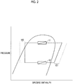
- the high-pressure refrigerant is supercooled by the gas-liquid heat exchanger 20, and on the other hand, as indicated by 101 in Fig. 2 , the low-temperature and low-pressure refrigerant which has passed through the evaporator 12 absorbs heat from the high-pressure refrigerant, thereby being overheated. Then, the temperature of the refrigerant which is suctioned into the compressor 14 rises.
- a predetermined target temperature Tv which is allowed for the compressor 14 can be determined in consideration of the performance of lubricating oil which is used in a sliding part of the compressor 14, or in a case where an electric motor is incorporated in the compressor 14, in consideration of the performance of the electric motor as well.
- the target temperature Tv which is the temperature of the refrigerant flowing through a discharge pipe that discharges the refrigerant compressed by the compressor 14 to the outside of the compressor 14 is determined.
- a target temperature range which includes the target temperature Tv and includes an upper limit temperature X and a lower limit temperature X- ⁇ is set.
- the flow rate of the high-pressure refrigerant flowing through the bypass path 21 is adjusted by using the bypass path 21 and the bypass valve 22. If an opening degree command corresponding to the flow rate is given from the control unit 25 to the bypass valve 22, the amount of the degree of opening of the bypass valve 22 is changed according to the opening degree command, whereby the flow rate of the refrigerant flowing through the bypass path 21 is adjusted.
- control unit 25 performs calculation with respect to each enthalpy derived using the pressure and temperature of the high-pressure refrigerant, the temperature of the refrigerant at an inlet of the gas-liquid heat exchanger 20, and the temperature of the refrigerant at an outlet of the gas-liquid heat exchanger 20.
- the refrigerant circuit system 1 of this embodiment is provided with a condenser temperature sensor 11A, a discharge temperature sensor 14A, an inlet temperature sensor 20A, and an outlet temperature sensor 20B.
- the condenser temperature sensor 11A detects the temperature of a gas-liquid two-phase refrigerant flowing through the condenser 11.
- the temperature detected by the condenser temperature sensor 11A is regarded as the temperature of a saturated vapor, and the pressure of the high-pressure refrigerant can be obtained as the saturated vapor pressure corresponding thereto.
- the value measured by the pressure gauge can be used as the pressure of the high-pressure refrigerant.
- the refrigerant circuit system 1 is also provided with a temperature sensor 12A which detects the temperature of a gas-liquid two-phase refrigerant flowing through the indoor heat exchanger 12 which functions as a condenser during the heating operation, for the control during the heating operation. During the heating operation, the pressure of the high-pressure refrigerant can be obtained by using the temperature detected by the temperature sensor 12A.
- the discharge temperature sensor 14A detects the temperature of the refrigerant flowing through the discharge pipe of the compressor 14 (hereinafter referred to as a discharged refrigerant).
- the inlet temperature sensor 20A detects the temperature of the high-pressure refrigerant flowing into the inlet of the gas-liquid heat exchanger 20.
- the outlet temperature sensor 20B detects the temperature of the high-pressure refrigerant flowing out from the outlet of the gas-liquid heat exchanger 20.
- the control unit 25 acquires h1 which is the enthalpy of the discharged refrigerant, based on the measurement value by the condenser temperature sensor 11A, or by using the pressure of the high-pressure refrigerant obtained by the pressure gauge and a temperature Td of the discharged refrigerant detected by the discharge temperature sensor 14A.
- enthalpy h2 of the refrigerant at the inlet of the gas-liquid heat exchanger 20 is acquired by using the temperature detected by the inlet temperature sensor 20A and the pressure of the high-pressure refrigerant
- enthalpy h3 of the refrigerant at the outlet of the gas-liquid heat exchanger 20 is acquired by using the temperature detected by the outlet temperature sensor 20B and the pressure of the high-pressure refrigerant.
- An enthalpy difference ⁇ h is acquired by the calculation of the value of h2-h3 using the enthalpy h2 at the inlet and the enthalpy h3 at the outlet acquired in this way. This corresponds to the effect of supercooling of the high-pressure refrigerant by the gas-liquid heat exchanger 20, and in other words, corresponds to the effect of overheating of the low-pressure refrigerant.
- the effects of supercooling and overheating by the gas-liquid heat exchanger 20 are reduced by an amount corresponding to the ratio of the flow rate which is caused to bypass, and therefore, a rise in the temperature of the low-pressure refrigerant according to heat radiation from the high-pressure refrigerant in the gas-liquid heat exchanger 20 is suppressed. Then, the temperature of the low-pressure refrigerant which is suctioned into the compressor 14 is lowered, and therefore, it becomes possible to suppress the temperature inside the compressor 14.
- the detected enthalpy difference ⁇ h indicates the effect that the gas-liquid heat exchanger 20 rises the temperature of the low-pressure refrigerant at the present time. Then, when discharge enthalpy corresponding to the temperature of the discharged refrigerant and the pressure of the high-pressure refrigerant, which will be detected in a case where the high-pressure refrigerant does not flow through the gas-liquid heat exchanger 20, is set to be h1', the current discharge enthalpy h1 can be expressed by the following expression (1).
- hl h 1 ′ + ⁇ h
- the case where the high-pressure refrigerant does not flow through the gas-liquid heat exchanger 20 corresponds to a case where the degree of opening of the bypass valve 22 is in a fully open condition.
- a target discharge enthalpy hv corresponding to the target temperature Tv of the discharged refrigerant, which is allowable for the compressor 14, can be expressed by the following expression (2) when an enthalpy difference by gas-liquid heat exchange is set to be ⁇ h'.
- hv h 1 ′ + ⁇ h
- ⁇ h' is a compatible enthalpy difference which is compatible with the target discharge enthalpy hv.
- ⁇ h' can be calculated by calculating the value of hv-hl' by the control unit 25.
- control unit 25 From the ratio of ⁇ h' to the current enthalpy difference ⁇ h based on the detected temperature, the control unit 25 obtains the control amount of the flow rate of the refrigerant which is caused to bypass through the bypass path 21, and gives it to the bypass valve 22 as the degree of opening.
- the control unit 25 determines the ratio of increase/decrease from the present time, of the flow rate of the high-pressure refrigerant which is caused to flow into the bypass path 21, based on the ratio of ( ⁇ h'/ ⁇ h) at the present time, and gives an opening degree command corresponding to the flow rate multiplied by the ratio of increase/decrease to the bypass valve 22.
- a width is given to the target discharge enthalpy hv such that the temperature of the discharged refrigerant falls within a predetermined temperature range which includes the target temperature Tv, and ⁇ h' is calculated so as to be compatible with a range from the upper limit to the lower limit of the enthalpy.
- control unit 25 has been described taking the cooling operation as an example. However, the same applies to the heating operation.
- the refrigerant circulates through the compressor 14, the indoor heat exchanger 12 as a condenser, the decompression unit 152, the gas-liquid heat exchanger 20, and the outdoor heat exchanger 11 as an evaporator in this order.
- the enthalpy difference ⁇ h due to the heat exchange in the gas-liquid heat exchanger 20 corresponds to the value of h3-h2, which is obtained by subtracting the enthalpy h2 corresponding to the temperature detected by the temperature sensor 20A from the enthalpy h3 corresponding to the temperature detected by the temperature sensor 20B.
- the processing which is the same as during the cooling operation except that the enthalpy difference ⁇ h corresponds to the value of h3-h2 and that the discharge enthalpy h1 is acquired by using the pressure of the high-pressure refrigerant corresponding to the condenser temperature detected by the temperature sensor 12A of the indoor heat exchanger 12 can be performed.
- ⁇ Gr corresponds to an increase/decrease magnification of the heat exchange amount by the gas-liquid heat exchanger 20.
- control unit 25 performs calculation according to the procedure shown in Fig. 3 and changes the degree of opening of the bypass valve 22, based on the calculated ⁇ Gr.
- the operation is started in a state where the bypass valve 22 is fully closed.
- the discharge enthalpy h1 is acquired by using the condenser temperature sensor 11A or using the pressure of the high-pressure refrigerant obtained by the pressure gauge and the temperature Td of the discharged refrigerant detected by the discharge temperature sensor 14A (step S1).
- the enthalpy h2 of the refrigerant at the inlet of the gas-liquid heat exchanger 20 and the enthalpy h3 of the refrigerant at the outlet are acquired by using the temperatures which are respectively detected by the temperature sensors 20A and 20B and the enthalpy difference ⁇ h due to gas-liquid heat exchange is calculated (step S2).
- step S3 the enthalpy difference ⁇ h' corresponding to the heat exchange amount of the gas-liquid heat exchanger 20, which is necessary for making the temperature of the discharged refrigerant reach the target temperature Tv, is calculated (step S3).
- the target temperature range is set by using a threshold value.
- the target temperature range includes the target temperature Tv and has an upper limit temperature X and a lower limit temperature (X- ⁇ ).
- An enthalpy range which includes the target discharge enthalpy hv is also set by an upper limit discharge enthalpy corresponding to the upper limit temperature X and a lower limit discharge enthalpy corresponding to the lower limit temperature (X- ⁇ ).
- the control unit 25 calculates ⁇ h' which is allowed to be added to the discharge enthalpy h1' in a case where the high-pressure refrigerant does not flow through the gas-liquid heat exchanger 20, such that the target discharge enthalpy hv falls within a range equal to or more than the lower limit enthalpy corresponding to the temperature (X- ⁇ ) and equal to or less than the upper limit enthalpy corresponding to the temperature X.
- the ratio ( ⁇ h' / ⁇ h) of ⁇ h' to ⁇ h is calculated as the increase/decrease magnification ⁇ Gr of the gas-liquid heat exchange amount (step S4). If ⁇ Gr is smaller than 1, in order to suppress the temperature of the discharged refrigerant, it is necessary to further reduce the flow rate of the high-pressure refrigerant flowing through the gas-liquid heat exchanger 20 than at the present time.
- the degree of opening of the bypass valve 22 can be changed by the following procedure according to the calculated ⁇ Gr.
- step S5 in a case where ⁇ Gr is smaller than 1 (Y in step S5), as long as the degree of opening of the bypass valve 22 is not in a fully open condition (N in step S6), an opening degree command to increase the degree of opening is given to the bypass valve 22 in order to reduce the flow rate of the high-pressure refrigerant flowing through the gas-liquid heat exchanger 20 (step S7). Then, the bypass valve 22 is driven to the opening degree amount corresponding to (1/ ⁇ Gr) times that at the present time, based on the opening degree command. For example, the bypass valve 22 is driven by a drive pulse in which a pulse number per unit time is about (1/ ⁇ Gr) times that at the present time.
- the minimum pulse number is set to be 0.01 or the like such that the bypass valve 22 can be opened even if the current pulse number is 0, because the bypass valve 22 is fully closed at the present time.
- step S10 in a case where ⁇ Gr is larger than 1 (Y in step S8), as long as the degree of opening of the bypass valve 22 is not in a fully closed condition (N in step S9), an opening degree command to reduce the degree of opening is given to the bypass valve 22 in order to increase the flow rate of the high-pressure refrigerant flowing in the gas-liquid heat exchanger 20 (step S10).
- step S11 the heat exchange amount by the gas-liquid heat exchanger 20 is compatible with the target temperature Tv, and therefore, the degree of opening of the bypass valve 22 is maintained as it is.
- the refrigerant circulation amount to the evaporator 12 does not decrease and the heat exchange performance of the evaporator 12 can be maintained.
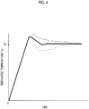
- the dot-and-dash line shown in Fig. 4 shows a case where the bypass flow rate is lowered at once by the bypass valve 22 because the temperature of the discharged refrigerant has exceeded the temperature Tv which is allowed for the compressor. In this case, the temperature of the discharged refrigerant excessively responds, and thus overshoot or hunting easily occurs.
- the broken line shown in Fig. 4 shows a case where the bypass flow rate is gradually lowered by the bypass valve 22 when the temperature of the discharged refrigerant has exceeded the temperature Tv which is allowed for the compressor 14. In this case, the bypass flow rate is insufficient, and thus there is a possibility that the discharge temperature cannot be lowered to the allowable temperature Tv.
- the temperature of the discharged refrigerant appropriately follows a change in the magnitude of the effect of the gas-liquid heat exchange according to a change in ⁇ Gr, and therefore, the temperature of the discharged refrigerant is stabilized to the target temperature Tv at an early stage. Since the refrigerant caused to bypass is caused to flow into the upstream of the decompression unit 151 which is distant from the compressor 14, avoidance of oversensitive response of the temperature of the discharged refrigerant also contributes to the stabilization of the discharge temperature.
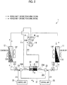
- bypass valve 22 of this embodiment it is also possible to use a flow rate regulating unit 23 capable of adjusting the flow rate of the refrigerant flowing into the bypass path 21, as shown in Fig. 5 .
- the flow rate regulating unit 23 and the control unit 25 on the right side in Fig. 5 which function during the cooling operation, and the flow rate regulating unit 23 and the control unit 25 on the left side in Fig. 5 , which function during the heating operation, are switched and used.
- the flow rate regulating unit 23 can cause the whole amount of the high-pressure refrigerant that passes through the condenser 11 and flows toward the gas-liquid heat exchanger 20 to flow into the bypass path 21, as necessary. If the whole amount of the high-pressure refrigerant flows into the bypass path 21, the high-pressure refrigerant does not flow through the gas-liquid heat exchanger 20 at all, and therefore, heat is not radiated from the high-pressure refrigerant to the low-pressure refrigerant, so that it is possible to suppress the temperature of the compressor 14 into which the low-pressure refrigerant is suctioned.
- the refrigerant circuit system according to the present invention can also be configured as a system for only the cooling operation or a system for only the heating operation.
- the four-way valve 13 is not necessary and only one decompression unit 15 is needed.
- the condenser temperature sensor is also prepared for only the heat exchanger functioning as a condenser, out of the two heat exchangers 11 and 12.
- the refrigerant circuit system according to the present invention can be applied not only to an air conditioner but also to an appropriate device using a refrigeration cycle, such as a freezer or a water heater.
Landscapes
- Engineering & Computer Science (AREA)
- Mechanical Engineering (AREA)
- General Engineering & Computer Science (AREA)
- Physics & Mathematics (AREA)
- Thermal Sciences (AREA)
- Chemical & Material Sciences (AREA)
- Combustion & Propulsion (AREA)
- Air Conditioning Control Device (AREA)
- Compression-Type Refrigeration Machines With Reversible Cycles (AREA)
Applications Claiming Priority (2)
| Application Number | Priority Date | Filing Date | Title |
|---|---|---|---|
| JP2016242022A JP6781034B2 (ja) | 2016-12-14 | 2016-12-14 | 冷媒回路システムおよび冷媒回路システムの制御方法 |
| PCT/JP2017/040965 WO2018110185A1 (fr) | 2016-12-14 | 2017-11-14 | Système de circuit de fluide frigorigène et procédé de commande d'un tel système |
Publications (2)
| Publication Number | Publication Date |
|---|---|
| EP3460357A1 true EP3460357A1 (fr) | 2019-03-27 |
| EP3460357A4 EP3460357A4 (fr) | 2019-07-03 |
Family
ID=62558523
Family Applications (1)
| Application Number | Title | Priority Date | Filing Date |
|---|---|---|---|
| EP17881376.2A Withdrawn EP3460357A4 (fr) | 2016-12-14 | 2017-11-14 | Système de circuit de fluide frigorigène et procédé de commande d'un tel système |
Country Status (3)
| Country | Link |
|---|---|
| EP (1) | EP3460357A4 (fr) |
| JP (1) | JP6781034B2 (fr) |
| WO (1) | WO2018110185A1 (fr) |
Cited By (1)
| Publication number | Priority date | Publication date | Assignee | Title |
|---|---|---|---|---|
| CN110195925A (zh) * | 2019-05-31 | 2019-09-03 | 宁波奥克斯电气股份有限公司 | 一种低温空气源热泵喷焓阀的控制方法及空调器 |
Families Citing this family (10)
| Publication number | Priority date | Publication date | Assignee | Title |
|---|---|---|---|---|
| JP6929318B2 (ja) * | 2019-03-28 | 2021-09-01 | 東プレ株式会社 | 冷凍装置及び冷凍装置の運転方法 |
| CN110486917B (zh) * | 2019-08-23 | 2021-06-22 | 广东美的暖通设备有限公司 | 运行控制装置及方法、空调器和计算机可读存储介质 |
| SE545516C2 (en) | 2020-01-30 | 2023-10-03 | Swep Int Ab | A refrigeration system and method for controlling such a refrigeration system |
| CN113091205B (zh) * | 2020-08-19 | 2022-03-08 | 广州松下空调器有限公司 | 一种空调器异常检测方法及装置 |
| CN216346591U (zh) * | 2021-09-18 | 2022-04-19 | 青岛海尔空调电子有限公司 | 空调器 |
| JP7615351B2 (ja) * | 2021-11-30 | 2025-01-16 | 三菱電機株式会社 | 空気調和装置 |
| CN114738934B (zh) * | 2022-03-29 | 2024-05-14 | 青岛海尔空调电子有限公司 | 一种空调器故障检测方法、检测装置及空调器 |
| CN115289604B (zh) * | 2022-08-12 | 2024-07-23 | 珠海格力电器股份有限公司 | 制热过负荷保护方法和装置、空调器 |
| JP2025035117A (ja) * | 2023-09-01 | 2025-03-13 | 三菱重工サーマルシステムズ株式会社 | 空気調和機 |
| JP7601171B1 (ja) * | 2023-09-29 | 2024-12-17 | 株式会社富士通ゼネラル | 冷凍サイクル装置及び冷凍サイクル装置の制御方法 |
Family Cites Families (11)
| Publication number | Priority date | Publication date | Assignee | Title |
|---|---|---|---|---|
| JP3484866B2 (ja) * | 1995-08-04 | 2004-01-06 | 三菱電機株式会社 | 冷凍装置 |
| JPH1068553A (ja) * | 1996-08-27 | 1998-03-10 | Daikin Ind Ltd | 空気調和機 |
| JP2002349977A (ja) * | 2001-05-24 | 2002-12-04 | Denso Corp | ヒートポンプサイクル |
| JP2003130481A (ja) * | 2001-10-24 | 2003-05-08 | Mitsubishi Heavy Ind Ltd | 自動車用空調装置の蒸気圧縮式冷凍サイクル |
| JP2003214713A (ja) * | 2002-01-23 | 2003-07-30 | Matsushita Electric Ind Co Ltd | 冷凍サイクル装置 |
| JP4407689B2 (ja) * | 2006-11-13 | 2010-02-03 | 三菱電機株式会社 | ヒートポンプ給湯機 |
| JP4740984B2 (ja) * | 2008-06-19 | 2011-08-03 | 三菱電機株式会社 | 冷凍空調装置 |
| JP2011043273A (ja) * | 2009-08-20 | 2011-03-03 | Panasonic Corp | ヒートポンプ式加熱液体システム |
| CN105074351B (zh) * | 2013-03-12 | 2017-03-22 | 三菱电机株式会社 | 空调装置 |
| JP6282135B2 (ja) * | 2014-02-17 | 2018-02-21 | 東芝キヤリア株式会社 | 冷凍サイクル装置 |
| DE102014222849A1 (de) * | 2014-11-10 | 2016-05-12 | BSH Hausgeräte GmbH | Haushaltskältegerät und Kältemaschine dafür |
-
2016
- 2016-12-14 JP JP2016242022A patent/JP6781034B2/ja active Active
-
2017
- 2017-11-14 WO PCT/JP2017/040965 patent/WO2018110185A1/fr not_active Ceased
- 2017-11-14 EP EP17881376.2A patent/EP3460357A4/fr not_active Withdrawn
Cited By (1)
| Publication number | Priority date | Publication date | Assignee | Title |
|---|---|---|---|---|
| CN110195925A (zh) * | 2019-05-31 | 2019-09-03 | 宁波奥克斯电气股份有限公司 | 一种低温空气源热泵喷焓阀的控制方法及空调器 |
Also Published As
| Publication number | Publication date |
|---|---|
| WO2018110185A1 (fr) | 2018-06-21 |
| JP6781034B2 (ja) | 2020-11-04 |
| JP2018096621A (ja) | 2018-06-21 |
| EP3460357A4 (fr) | 2019-07-03 |
Similar Documents
| Publication | Publication Date | Title |
|---|---|---|
| JP6781034B2 (ja) | 冷媒回路システムおよび冷媒回路システムの制御方法 | |
| EP3147587B1 (fr) | Dispositif de climatisation | |
| EP3199889B1 (fr) | Climatiseur d'air | |
| US20190049154A1 (en) | Air-conditioning apparatus | |
| EP3252402B1 (fr) | Pompe à chaleur | |
| EP3859244B1 (fr) | Climatiseur | |
| JP6545252B2 (ja) | 冷凍サイクル装置 | |
| EP2122276B1 (fr) | Contrôle de limitation sans refroidissement pour des systèmes de climatisation | |
| KR20100123729A (ko) | 냉동장치 | |
| EP1431677B1 (fr) | Climatiseur | |
| EP2068095A1 (fr) | Dispositif de réfrigération | |
| JP3864980B2 (ja) | 空気調和機 | |
| JP7138801B2 (ja) | 冷凍サイクル装置 | |
| EP3575712B1 (fr) | Système de refroidissement | |
| US20160252290A1 (en) | Heat-source-side unit and air-conditioning apparatus | |
| EP3109566B1 (fr) | Dispositif de climatisation | |
| EP3922928A1 (fr) | Unité extérieure de dispositif de réfrigération et dispositif de réfrigération comprenant celle-ci | |
| JP7055239B2 (ja) | 空気調和装置 | |
| EP3062041A1 (fr) | Dispositif de réfrigération | |
| JP2017088137A (ja) | 車両用空調装置の冷凍サイクル及びこれを搭載した車両 | |
| US11585578B2 (en) | Refrigeration cycle apparatus | |
| EP2672205A2 (fr) | Système échangeur de chaleur | |
| EP4464956A1 (fr) | Dispositif de réfrigération et appareil de test environnemental | |
| EP2479516A2 (fr) | Pompe à chaleur | |
| TWI807163B (zh) | 冷凍裝置及冷凍裝置之運轉方法 |
Legal Events
| Date | Code | Title | Description |
|---|---|---|---|
| STAA | Information on the status of an ep patent application or granted ep patent |
Free format text: STATUS: THE INTERNATIONAL PUBLICATION HAS BEEN MADE |
|
| PUAI | Public reference made under article 153(3) epc to a published international application that has entered the european phase |
Free format text: ORIGINAL CODE: 0009012 |
|
| STAA | Information on the status of an ep patent application or granted ep patent |
Free format text: STATUS: REQUEST FOR EXAMINATION WAS MADE |
|
| 17P | Request for examination filed |
Effective date: 20181218 |
|
| AK | Designated contracting states |
Kind code of ref document: A1 Designated state(s): AL AT BE BG CH CY CZ DE DK EE ES FI FR GB GR HR HU IE IS IT LI LT LU LV MC MK MT NL NO PL PT RO RS SE SI SK SM TR |
|
| AX | Request for extension of the european patent |
Extension state: BA ME |
|
| A4 | Supplementary search report drawn up and despatched |
Effective date: 20190604 |
|
| RIC1 | Information provided on ipc code assigned before grant |
Ipc: F25B 13/00 20060101ALI20190528BHEP Ipc: F25B 1/00 20060101AFI20190528BHEP Ipc: F24F 11/84 20180101ALI20190528BHEP Ipc: F25B 40/00 20060101ALI20190528BHEP |
|
| STAA | Information on the status of an ep patent application or granted ep patent |
Free format text: STATUS: THE APPLICATION HAS BEEN WITHDRAWN |
|
| 18W | Application withdrawn |
Effective date: 20191114 |