EP3460414B1 - Capteur disposé dans un boîtier à raccordement électrique - Google Patents
Capteur disposé dans un boîtier à raccordement électrique Download PDFInfo
- Publication number
- EP3460414B1 EP3460414B1 EP18196023.8A EP18196023A EP3460414B1 EP 3460414 B1 EP3460414 B1 EP 3460414B1 EP 18196023 A EP18196023 A EP 18196023A EP 3460414 B1 EP3460414 B1 EP 3460414B1
- Authority
- EP
- European Patent Office
- Prior art keywords
- sensor
- spring
- housing
- pressure
- contact area
- Prior art date
- Legal status (The legal status is an assumption and is not a legal conclusion. Google has not performed a legal analysis and makes no representation as to the accuracy of the status listed.)
- Active
Links
Images
Classifications
-
- G—PHYSICS
- G01—MEASURING; TESTING
- G01D—MEASURING NOT SPECIALLY ADAPTED FOR A SPECIFIC VARIABLE; ARRANGEMENTS FOR MEASURING TWO OR MORE VARIABLES NOT COVERED IN A SINGLE OTHER SUBCLASS; TARIFF METERING APPARATUS; MEASURING OR TESTING NOT OTHERWISE PROVIDED FOR
- G01D11/00—Component parts of measuring arrangements not specially adapted for a specific variable
- G01D11/24—Housings ; Casings for instruments
- G01D11/245—Housings for sensors
Definitions
- the invention relates generally to a sensor for detecting a physical or chemical property from the surroundings of the sensor, which has a housing (housed sensor) with an external electrical connection.
- the invention relates in particular to a pressure sensor designed in this way.
- a sensor analog, digital or binary
- a measuring device which has one or more variables based on at least one physical or chemical effect, which are in a defined, regularly proportional relationship to a physical or chemical variable to be determined (measured variable) stands.
- frequently used measurement variables are, for example, pressure, temperature, flow, distance, level, length, position, humidity, pH value, material properties and many other things.
- the variable of the sensor is a physical or chemical property of the sensor, which is set on the basis of the measured variable in the sensor and is converted into a processable, regularly electrical, measurement signal.
- the measurement signal can be output analog or digital and as a data and / or control signal.
- the DE2350252 discloses an electrochemical sensor.
- a housed sensor regularly includes a variable having measuring transducers, a device for generating the measuring signal and its transmission. It can also have one or more devices for processing the measurement signal. These components are partially or completely encased in a housing such that the functionality of the sensor is not disturbed by external influences and / or sensor components are not damaged.
- the housing has an external electrical connection. This is electrically connected within the housing to the devices for generating and possibly processing the measurement signal.
- connection should be compatible with the connections of the external devices and be easily connectable to them, and should ensure a safe and permanent electrical contact under measurement conditions.
- the connection is regularly carried out by a socket with one or more pins into which a corresponding plug of the external device can be inserted.
- connection of the sensor according to the invention is formed by a spring, or a plurality thereof, which extends from a contact surface inside the housing (inner contact surface) through the housing wall and outwards, for example by means of an end of the spring located outside the housing, an outer one Contact area forms.
- the spring which provides an electrically conductive path for this purpose, the inner and the outer contact surface are electrically connected to one another in a suitable manner connectable.
- the electrical contact between the spring and the inner contact surface can be detachable or non-detachable.
- the latter is done, for example, by a solder connection, the former, for example, by a mechanical connection such as a clamp or screw connection.
- a mechanical connection such as a clamp or screw connection. It is also possible for the spring to rest loosely on the inner contact surface, with reliable mechanical and electrical contact being provided when the spring is under pressure.
- the spring can be designed in such a way that, when it is in electrical contact with a connector of an external device, it is subjected to pressure. Alternatively, it can be pretensioned so that it is relaxed to produce an electrical contact.
- the spring may extend through the housing wall in various ways depending on the application of the sensor, the design of the spring, or other conditions.
- a passage through the housing wall or a recess can be formed on an edge region of a housing component.
- a gap between housing components can be used or designed accordingly.
- a spring is to be understood here as a structural element which can take up work on a relatively large path and can store it in whole or in part as deformation energy in order to release it in part or in full when it is relieved.
- the material and design of the spring in accordance with the existing measurement and environmental conditions and the design of the sensor, are designed to make a secure physical and electrical contact both to the inner contact surface and to the connector of the external device.
- the person skilled in the art has various designs of springs and a wide variety of materials at his disposal, from which he selects suitable ones.
- conductive, elastic plastics or composite materials can also be used to form the electrical connection between the inner and outer contact surface.
- the spring can be coated entirely or at least in the area of the electrical contact with materials which have a low electrical contact resistance and low corrosion, such as noble metals.
- the spring can be designed, for example, as a cylindrical or conical coil spring, as a cylindrical or conical compression rod, as a leaf spring or a spring of another shape. Springs with a curved longitudinal cross section or other, even changing, cross sections are also possible.
- the spring contact surface lying outside the housing, which forms an outer contact surface of the sensor, can be enlarged in another way to improve the contact capability by flattening. Furthermore, material can be used in this area of the spring, which is a good one electrical contact realized.
- Suitable forms of spring such as a spring subjected to torsion, can cause a friction (scratching) of the surfaces meeting one another in the course of the production of the physical contact, as a result of which thin layers of corrosion can be eliminated. Scratching can be implemented if the movement of the spring to generate the spring tension and / or to relieve it has two directional components that differ from one another.
- the first directional component should be the one for tensioning or relieving the spring, e.g. B. in the Z direction and the other can be the X or Y direction, so that when the outer contact surface of the spring strikes the external contact, both contact partners slide against one another.
- a direction deviating by an angle of X or Y is included according to the general rules for the composition of a movement path, since such a movement path also includes an X or Y component. The same effect is achieved if the external connector with which the sensor is to be contacted is moved instead of the sensor.
- the inclination of the outer contact surface can automatically adapt to a limited extent to the inclination of the contact surface of the connector of the external device in the course of establishing the physical contact if the spring protrudes sufficiently far from the housing.
- the maximum protrusion of the spring over the housing wall and the maximum adjustable inclination are determined by the fact that the spring does not deflect and so there is no reproducible contact is coming. Such a position of the outer contact surface can also trigger scratching.
- the inner contact surface can be assigned to a device for generating and transmitting the measurement signal or to a device for processing the measurement signal. It can be arranged, for example, on a board which has electronic components and / or the measurement sensor and electrical conductors for the electrical connection to the components and / or to the measurement sensor.
- the spring is guided by a guide element along its path to be covered in the course of the change in shape, so that the spring cannot deflect along this path and a reproducible physical and electrical contact is achieved.
- the guide element can be arranged inside the housing or outside of it.
- the guide element can be designed in or on the sensor in various ways depending on the design of the sensor. For example, it can be integrated in the housing wall or an inner component of the sensor. Alternatively, it can also be implemented as a separate element.
- the spring can be designed as a detachable component of the sensor, as an alternative to a detachable connection to the inner contact surface, or can be held in the sensor in various ways. It can, for example, be inserted loosely in the passage, the recess or the slot or the like on the sensor designed for the spring, or it can be jammed in it by its shape. For example, it can be in the guide element. Also a fixation in the Guide element or by means of detachable holding means or on the inner contact surface is possible.
- the sensor can have several such contact surfaces realized by springs. This can serve different assignments, for example the assignment with the measurement signal, with ground and the supply and control of the sensor.
- the housing of the sensor is designed according to its application. It regularly has a basic housing body and a housing cover which is connected to the basic housing body. These can in turn be formed in one or more parts and / or at least partially by other components of the sensor.
- the housing can also include internal components, for example in order to separate spaces from one another in the interior of the sensor.
- the design of the outer contact surface of the sensor by means of one or more springs in the configurations described above makes it possible for a contact surface of the connector of an external device to be placed only on an outer contact surface, which simplifies the production of the contact and also in places that are difficult to access small space the contact can be made.
- the two connection partners can be fixed releasably or permanently in the contact position, for example by means of holding means arranged on the housing.
- Such a sensor is designed, for example, as a pressure sensor.
- pressure sensors comprise a housing with a pressure opening, on which the medium is present, the pressure of which is to be measured.
- the known pressure sensors regularly have a pressure port protruding into the housing as a pressure opening.
- the pressure opening or, if applicable, the pressure port is equipped with a micromechanical pressure sensor (sensor chip) arranged in the housing.
- the pressure sensor is arranged in such a way that it closes the pressure opening on one side, so that pressure acts directly on the pressure sensor.
- the pressure sensor can be connected to an electrical conductor board for electrical contacting.
- Electronic components and optionally an integrated circuit for processing the measurement signals can also be arranged on the board on the latter.
- the senor For the electrical connection to an external device, the sensor has external contacts which are formed by means of springs as described above and are electrically connected to internal contact surfaces which are arranged, for example, on the board.
- the interior of the housing is often subdivided in such a way that it can be used as an absolute pressure sensor or differential pressure sensor (also open to the ambient pressure) and / or certain components in the sensor can be protected from the physical and chemical measurement conditions.
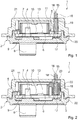
- the associated 1 and 2 show alternative embodiments of the sensor described above using the example of pressure sensors.
- the in Fig. 1 Pressure sensor 1 shown in a section comprises a board 3, which functions as a circuit carrier and on one side, hereinafter referred to as front side 5, the further components of the pressure sensor 1 are mounted and structures of conductor tracks 10 are formed which electrically connect the individual components to one another.
- the board 3 has a passage (not shown), the pressure opening 9.
- a measuring sensor 7, in the exemplary embodiment is a pressure sensor 7, is fastened on the base 4 above the pressure opening 9, so that it closes the pressure opening 9.
- the base 4 has a corresponding passage (not shown), so that the pressure opening 9 opens out on the rear side 6 of the board 3 and, when the pressure sensor 1 is installed, is open to the liquid.
- the pressure opening 9 and possibly also the passage of the base are closed by the membrane of the pressure sensor 7.
- a fluid applied via a pressure connection 8 in the pressure opening 9 acts on the membrane of the pressure sensor 7.
- the pressure sensor 1 can also be implemented with another suitable pressure sensor 7.
- a suitable integrated circuit 13 is mounted on the front of the board 3 for signal conditioning of the signals picked up by the measuring resistors. This is electrically connected to the conductor tracks 10 of the board 3.
- the pressure sensor 7 with the base 4 and the integrated circuit 13 are enclosed by a frame element 11, which is mounted, for example, on the board and for Protection of the electronic components can be filled with a medium-resistant and pressure-transmitting gel (not shown).
- inner contact surfaces 17 are also in electrical contact with the conductor tracks 10 and via these with the integrated circuit 13.
- the inner contact surfaces 17 are outside the frame element 11 arranged. If the pressure regime and the applied medium allow it, the frame element 11 can be omitted and / or the inner contact surfaces 17 can be formed elsewhere.
- the pressure sensor 1 has a housing 2, which is formed from a housing cover 21 and a housing base 20.
- the pressure port 8 is formed on the housing base 20.
- Housing cover 21 and housing base 20 are tightly connected to one another with respect to the surrounding medium.
- the housing 2 surrounds the board 3 with the components arranged thereon and consists of a material which is chemically resistant to the fluid with which the pressure sensor 1 comes into contact.
- a metallic spring 8 on each of the inner contact surfaces 17.
- this is a helical spring 18.
- the helical spring 18 forms in connection with the inner contact surface 17 an electrical connection 15 of the pressure sensor 1, via which signal transmissions or the electrical supply of the pressure sensor 1 to or from external devices can be realized.
- the coil spring 18 extends through a passage 19 in the housing cover 21 to beyond its outer wall surface.
- the cross section of the passage 19 corresponds to the cross section of the helical spring 18 and is only slightly larger, so that the helical spring 18 can just move freely in the passage 19.
- the passage 19 serves as a guide element for the helical spring 18.
- the end of the helical spring 18 lying outside the housing represents the outer contact surface 16 of the sensor 1. Via the inner and outer contact surfaces 17, 16, the signals from the pressure transducer 7, which are processed by the integrated circuit 13, can be transmitted to an external device.
- the embodiment in Fig. 2 differs from that in Fig. 1 through the design of the guide element.
- This is also formed as a passage 19 here in a widened wall section 22 of the frame element 11.
- the passage 19 opens out at a corresponding opening 23 in the housing cover 21, through which the helical spring 18 extends outside the housing 2.
- the exemplary embodiments are merely illustrative and are not to be understood as restricting with regard to the type of sensor and the sensor design.
- the person skilled in the art would readily combine the features described above with one another in a different way than described if he considered this to be obvious and sensible.
- the present invention is defined in the following claims.
Landscapes
- Physics & Mathematics (AREA)
- General Physics & Mathematics (AREA)
- Measuring Fluid Pressure (AREA)
Claims (8)
- Capteur destiné à détecter une propriété physique ou chimique dans l'environnement du capteur (1), lequel comporte au moins les composants suivants :
un détecteur de mesure (7), un dispositif destiné à générer un signal de mesure et à le transmettre, un boîtier (2) destiné à protéger au moins l'un desdits composants, et au moins une borne électrique externe destinée à délivrer un signal électrique de mesure, caractérisé en ce que la borne électrique est formée par un ressort (18) en liaison avec une surface de contact à l'intérieur du boîtier (2), ci-après désignée surface de contact interne (17), dans lequel le ressort (18) s'étend depuis la surface de contact interne (17) à travers la paroi du boîtier et forme une surface de contact externe (16) à l'extérieur du boîtier (2), dans lequel un trajet électriquement conducteur entre la surface de contact interne (17) et la surface de contact externe (16) peut être établi au moyen du ressort (18). - Capteur selon la revendication 1, caractérisé en ce que le ressort (18) est constitué et/ou est revêtu au moins par sections d'un matériau métallique ou d'une matière plastique élastique électriquement conductrice ou d'un matériau composite.
- Capteur selon l'une des revendications précédentes, caractérisé en ce que le contact électrique entre le ressort (18) et la surface de contact interne (17) est conçu pour être amovible ou inamovible.
- Capteur selon l'une des revendications précédentes, caractérisé en ce que le ressort (18) présente une forme telle que son mouvement qui est destiné à produire la tension et/ou à libérer la charge présente deux composantes directionnelles qui s'écartent l'une de l'autre.
- Capteur selon l'une des revendications précédentes, caractérisé en ce que le capteur (1) comporte un élément de guidage destiné à guider le ressort (18) le long d'un trajet devant être parcouru au cours de la déformation.
- Capteur selon l'une des revendications précédentes, caractérisé en ce que le ressort (18) est réalisé sous la forme d'un composant perdable du capteur (1) ou est maintenu dans le capteur (1) du fait de sa configuration.
- Capteur selon l'une des revendications précédentes, caractérisé en ce que la borne électrique sert à la mise à la terre du capteur (1), à la transmission du signal de mesure ou à l'alimentation en tension et/ou à la commande du capteur (1).
- Capteur selon l'une des revendications précédentes, caractérisé en ce que le capteur (1) est un capteur de pression, qui comporte un boîtier (2) avec une ouverture de pression à laquelle est appliqué le fluide à mesurer, et un détecteur de pression (7) qui referme d'un côté l'ouverture de pression.
Applications Claiming Priority (1)
| Application Number | Priority Date | Filing Date | Title |
|---|---|---|---|
| DE102017121906 | 2017-09-21 |
Publications (2)
| Publication Number | Publication Date |
|---|---|
| EP3460414A1 EP3460414A1 (fr) | 2019-03-27 |
| EP3460414B1 true EP3460414B1 (fr) | 2020-03-04 |
Family
ID=63678515
Family Applications (1)
| Application Number | Title | Priority Date | Filing Date |
|---|---|---|---|
| EP18196023.8A Active EP3460414B1 (fr) | 2017-09-21 | 2018-09-21 | Capteur disposé dans un boîtier à raccordement électrique |
Country Status (1)
| Country | Link |
|---|---|
| EP (1) | EP3460414B1 (fr) |
Family Cites Families (4)
| Publication number | Priority date | Publication date | Assignee | Title |
|---|---|---|---|---|
| DE2841771A1 (de) * | 1978-09-26 | 1980-04-03 | Bosch Gmbh Robert | Elektrochemischer messfuehler fuer die bestimmung des sauerstoffgehaltes in gasen |
| PL2312290T3 (pl) * | 2009-10-16 | 2020-06-01 | First Sensor Mobility Gmbh | Czujnik ciśnienia i jego zastosowanie w zbiorniku płynu |
| US8701476B2 (en) * | 2011-09-16 | 2014-04-22 | Tyco Electronics Brasil Ltda | Sensor assembly with resilient contact portions |
| DE102015221147A1 (de) * | 2015-10-29 | 2017-05-04 | Robert Bosch Gmbh | Verfahren zur Herstellung eines Sensors zur Erfassung mindestens einer Eigenschaft eines Mediums |
-
2018
- 2018-09-21 EP EP18196023.8A patent/EP3460414B1/fr active Active
Non-Patent Citations (1)
| Title |
|---|
| None * |
Also Published As
| Publication number | Publication date |
|---|---|
| EP3460414A1 (fr) | 2019-03-27 |
Similar Documents
| Publication | Publication Date | Title |
|---|---|---|
| DE102008042314B4 (de) | Messumformer zur Verbindung eines Sensorelements mit einer externen Einheit, und elektronischer Stecker zum Anschluss an ein elektronisches Gerät | |
| DE102014200093A1 (de) | Sensor zur Erfassung einer Temperatur und eines Drucks eines fluiden Mediums | |
| DE102015109311A1 (de) | Rundsteckverbinder zur Datenübertragung hoher Datenraten | |
| EP3236222B1 (fr) | Sonde de temperature et de pression | |
| DE10111336B4 (de) | Sensor, insbesondere Temperatur-Sensor, mit einem Messwiderstand | |
| DE102009026444A1 (de) | Steuergerät mit Drucksensor | |
| DE102014101968A1 (de) | Messgerät und Messeinsatz für ein solches Messgerät | |
| EP3460414B1 (fr) | Capteur disposé dans un boîtier à raccordement électrique | |
| DE102012102386B4 (de) | Sensorvorrichtung, die in einem Injektor einer internen Verbrennungsmaschine integriert ist | |
| DE102016106900A1 (de) | Verfahren zur Positionierung von Leiterplatten und Leiterplattenanordnung | |
| DE102011109006A1 (de) | Gehäuse für einen Halbleiterchip und Halbleiterchip mit einem Gehäuse | |
| DE102012012528A1 (de) | Messvorrichtung zum Bestimmen einer Prozessgröße | |
| DE102008059661B4 (de) | Optischer Sensor | |
| DE102007008072A1 (de) | Modulares Messgerät | |
| EP4439034A1 (fr) | Couvercle de protection et unité de mesure dotée d'un tel couvercle de protection | |
| DE102009049639A1 (de) | Schaltungsanordnungen zum Ermitteln der Richtung und des Betrags eines Feldvektors | |
| DE102022130669A1 (de) | Einschraubbares Verbindungselement zur Ex-i und Ex-d konformen Durchführung von elektrischen Signalen | |
| DE102008054618B4 (de) | Verfahren zur Fertigung einer Vorrichtung zur Bestimmung und/oder Überwachung einer Prozessgröße und entsprechende Vorrichtung | |
| EP1836841B1 (fr) | Dispositif de detection d'images | |
| DE102008023187A1 (de) | Ultraschallsensor | |
| DE102012213572A1 (de) | Kapazitiver Drucksensor | |
| DE102013214687B4 (de) | Drucksensor | |
| WO2013189484A1 (fr) | Étiquette rfid dotée d'une antenne f inversée | |
| DE102014107425B4 (de) | Erdungsvorrichtung | |
| DE102015206481A1 (de) | Elektronisches Steuergerät |
Legal Events
| Date | Code | Title | Description |
|---|---|---|---|
| PUAI | Public reference made under article 153(3) epc to a published international application that has entered the european phase |
Free format text: ORIGINAL CODE: 0009012 |
|
| STAA | Information on the status of an ep patent application or granted ep patent |
Free format text: STATUS: THE APPLICATION HAS BEEN PUBLISHED |
|
| AK | Designated contracting states |
Kind code of ref document: A1 Designated state(s): AL AT BE BG CH CY CZ DE DK EE ES FI FR GB GR HR HU IE IS IT LI LT LU LV MC MK MT NL NO PL PT RO RS SE SI SK SM TR |
|
| AX | Request for extension of the european patent |
Extension state: BA ME |
|
| STAA | Information on the status of an ep patent application or granted ep patent |
Free format text: STATUS: REQUEST FOR EXAMINATION WAS MADE |
|
| GRAP | Despatch of communication of intention to grant a patent |
Free format text: ORIGINAL CODE: EPIDOSNIGR1 |
|
| STAA | Information on the status of an ep patent application or granted ep patent |
Free format text: STATUS: GRANT OF PATENT IS INTENDED |
|
| 17P | Request for examination filed |
Effective date: 20190711 |
|
| RBV | Designated contracting states (corrected) |
Designated state(s): AL AT BE BG CH CY CZ DE DK EE ES FI FR GB GR HR HU IE IS IT LI LT LU LV MC MK MT NL NO PL PT RO RS SE SI SK SM TR |
|
| RIC1 | Information provided on ipc code assigned before grant |
Ipc: G01D 11/24 20060101AFI20190730BHEP |
|
| INTG | Intention to grant announced |
Effective date: 20190813 |
|
| GRAJ | Information related to disapproval of communication of intention to grant by the applicant or resumption of examination proceedings by the epo deleted |
Free format text: ORIGINAL CODE: EPIDOSDIGR1 |
|
| STAA | Information on the status of an ep patent application or granted ep patent |
Free format text: STATUS: REQUEST FOR EXAMINATION WAS MADE |
|
| GRAP | Despatch of communication of intention to grant a patent |
Free format text: ORIGINAL CODE: EPIDOSNIGR1 |
|
| STAA | Information on the status of an ep patent application or granted ep patent |
Free format text: STATUS: GRANT OF PATENT IS INTENDED |
|
| INTC | Intention to grant announced (deleted) | ||
| GRAS | Grant fee paid |
Free format text: ORIGINAL CODE: EPIDOSNIGR3 |
|
| GRAA | (expected) grant |
Free format text: ORIGINAL CODE: 0009210 |
|
| STAA | Information on the status of an ep patent application or granted ep patent |
Free format text: STATUS: THE PATENT HAS BEEN GRANTED |
|
| INTG | Intention to grant announced |
Effective date: 20200116 |
|
| AK | Designated contracting states |
Kind code of ref document: B1 Designated state(s): AL AT BE BG CH CY CZ DE DK EE ES FI FR GB GR HR HU IE IS IT LI LT LU LV MC MK MT NL NO PL PT RO RS SE SI SK SM TR |
|
| REG | Reference to a national code |
Ref country code: GB Ref legal event code: FG4D Free format text: NOT ENGLISH |
|
| REG | Reference to a national code |
Ref country code: CH Ref legal event code: EP |
|
| REG | Reference to a national code |
Ref country code: AT Ref legal event code: REF Ref document number: 1240911 Country of ref document: AT Kind code of ref document: T Effective date: 20200315 |
|
| REG | Reference to a national code |
Ref country code: DE Ref legal event code: R096 Ref document number: 502018000883 Country of ref document: DE |
|
| REG | Reference to a national code |
Ref country code: IE Ref legal event code: FG4D Free format text: LANGUAGE OF EP DOCUMENT: GERMAN |
|
| PG25 | Lapsed in a contracting state [announced via postgrant information from national office to epo] |
Ref country code: NO Free format text: LAPSE BECAUSE OF FAILURE TO SUBMIT A TRANSLATION OF THE DESCRIPTION OR TO PAY THE FEE WITHIN THE PRESCRIBED TIME-LIMIT Effective date: 20200604 Ref country code: FI Free format text: LAPSE BECAUSE OF FAILURE TO SUBMIT A TRANSLATION OF THE DESCRIPTION OR TO PAY THE FEE WITHIN THE PRESCRIBED TIME-LIMIT Effective date: 20200304 Ref country code: RS Free format text: LAPSE BECAUSE OF FAILURE TO SUBMIT A TRANSLATION OF THE DESCRIPTION OR TO PAY THE FEE WITHIN THE PRESCRIBED TIME-LIMIT Effective date: 20200304 |
|
| REG | Reference to a national code |
Ref country code: NL Ref legal event code: MP Effective date: 20200304 |
|
| PG25 | Lapsed in a contracting state [announced via postgrant information from national office to epo] |
Ref country code: BG Free format text: LAPSE BECAUSE OF FAILURE TO SUBMIT A TRANSLATION OF THE DESCRIPTION OR TO PAY THE FEE WITHIN THE PRESCRIBED TIME-LIMIT Effective date: 20200604 Ref country code: GR Free format text: LAPSE BECAUSE OF FAILURE TO SUBMIT A TRANSLATION OF THE DESCRIPTION OR TO PAY THE FEE WITHIN THE PRESCRIBED TIME-LIMIT Effective date: 20200605 Ref country code: HR Free format text: LAPSE BECAUSE OF FAILURE TO SUBMIT A TRANSLATION OF THE DESCRIPTION OR TO PAY THE FEE WITHIN THE PRESCRIBED TIME-LIMIT Effective date: 20200304 Ref country code: LV Free format text: LAPSE BECAUSE OF FAILURE TO SUBMIT A TRANSLATION OF THE DESCRIPTION OR TO PAY THE FEE WITHIN THE PRESCRIBED TIME-LIMIT Effective date: 20200304 Ref country code: SE Free format text: LAPSE BECAUSE OF FAILURE TO SUBMIT A TRANSLATION OF THE DESCRIPTION OR TO PAY THE FEE WITHIN THE PRESCRIBED TIME-LIMIT Effective date: 20200304 |
|
| REG | Reference to a national code |
Ref country code: LT Ref legal event code: MG4D |
|
| PG25 | Lapsed in a contracting state [announced via postgrant information from national office to epo] |
Ref country code: NL Free format text: LAPSE BECAUSE OF FAILURE TO SUBMIT A TRANSLATION OF THE DESCRIPTION OR TO PAY THE FEE WITHIN THE PRESCRIBED TIME-LIMIT Effective date: 20200304 |
|
| PG25 | Lapsed in a contracting state [announced via postgrant information from national office to epo] |
Ref country code: PT Free format text: LAPSE BECAUSE OF FAILURE TO SUBMIT A TRANSLATION OF THE DESCRIPTION OR TO PAY THE FEE WITHIN THE PRESCRIBED TIME-LIMIT Effective date: 20200729 Ref country code: ES Free format text: LAPSE BECAUSE OF FAILURE TO SUBMIT A TRANSLATION OF THE DESCRIPTION OR TO PAY THE FEE WITHIN THE PRESCRIBED TIME-LIMIT Effective date: 20200304 Ref country code: CZ Free format text: LAPSE BECAUSE OF FAILURE TO SUBMIT A TRANSLATION OF THE DESCRIPTION OR TO PAY THE FEE WITHIN THE PRESCRIBED TIME-LIMIT Effective date: 20200304 Ref country code: RO Free format text: LAPSE BECAUSE OF FAILURE TO SUBMIT A TRANSLATION OF THE DESCRIPTION OR TO PAY THE FEE WITHIN THE PRESCRIBED TIME-LIMIT Effective date: 20200304 Ref country code: EE Free format text: LAPSE BECAUSE OF FAILURE TO SUBMIT A TRANSLATION OF THE DESCRIPTION OR TO PAY THE FEE WITHIN THE PRESCRIBED TIME-LIMIT Effective date: 20200304 Ref country code: SM Free format text: LAPSE BECAUSE OF FAILURE TO SUBMIT A TRANSLATION OF THE DESCRIPTION OR TO PAY THE FEE WITHIN THE PRESCRIBED TIME-LIMIT Effective date: 20200304 Ref country code: LT Free format text: LAPSE BECAUSE OF FAILURE TO SUBMIT A TRANSLATION OF THE DESCRIPTION OR TO PAY THE FEE WITHIN THE PRESCRIBED TIME-LIMIT Effective date: 20200304 Ref country code: IS Free format text: LAPSE BECAUSE OF FAILURE TO SUBMIT A TRANSLATION OF THE DESCRIPTION OR TO PAY THE FEE WITHIN THE PRESCRIBED TIME-LIMIT Effective date: 20200704 Ref country code: SK Free format text: LAPSE BECAUSE OF FAILURE TO SUBMIT A TRANSLATION OF THE DESCRIPTION OR TO PAY THE FEE WITHIN THE PRESCRIBED TIME-LIMIT Effective date: 20200304 |
|
| REG | Reference to a national code |
Ref country code: DE Ref legal event code: R097 Ref document number: 502018000883 Country of ref document: DE |
|
| PLBE | No opposition filed within time limit |
Free format text: ORIGINAL CODE: 0009261 |
|
| STAA | Information on the status of an ep patent application or granted ep patent |
Free format text: STATUS: NO OPPOSITION FILED WITHIN TIME LIMIT |
|
| PG25 | Lapsed in a contracting state [announced via postgrant information from national office to epo] |
Ref country code: IT Free format text: LAPSE BECAUSE OF FAILURE TO SUBMIT A TRANSLATION OF THE DESCRIPTION OR TO PAY THE FEE WITHIN THE PRESCRIBED TIME-LIMIT Effective date: 20200304 Ref country code: DK Free format text: LAPSE BECAUSE OF FAILURE TO SUBMIT A TRANSLATION OF THE DESCRIPTION OR TO PAY THE FEE WITHIN THE PRESCRIBED TIME-LIMIT Effective date: 20200304 |
|
| 26N | No opposition filed |
Effective date: 20201207 |
|
| PG25 | Lapsed in a contracting state [announced via postgrant information from national office to epo] |
Ref country code: PL Free format text: LAPSE BECAUSE OF FAILURE TO SUBMIT A TRANSLATION OF THE DESCRIPTION OR TO PAY THE FEE WITHIN THE PRESCRIBED TIME-LIMIT Effective date: 20200304 Ref country code: SI Free format text: LAPSE BECAUSE OF FAILURE TO SUBMIT A TRANSLATION OF THE DESCRIPTION OR TO PAY THE FEE WITHIN THE PRESCRIBED TIME-LIMIT Effective date: 20200304 |
|
| REG | Reference to a national code |
Ref country code: BE Ref legal event code: MM Effective date: 20200930 |
|
| PG25 | Lapsed in a contracting state [announced via postgrant information from national office to epo] |
Ref country code: LU Free format text: LAPSE BECAUSE OF NON-PAYMENT OF DUE FEES Effective date: 20200921 |
|
| PG25 | Lapsed in a contracting state [announced via postgrant information from national office to epo] |
Ref country code: BE Free format text: LAPSE BECAUSE OF NON-PAYMENT OF DUE FEES Effective date: 20200930 Ref country code: IE Free format text: LAPSE BECAUSE OF NON-PAYMENT OF DUE FEES Effective date: 20200921 |
|
| REG | Reference to a national code |
Ref country code: CH Ref legal event code: PL |
|
| PG25 | Lapsed in a contracting state [announced via postgrant information from national office to epo] |
Ref country code: TR Free format text: LAPSE BECAUSE OF FAILURE TO SUBMIT A TRANSLATION OF THE DESCRIPTION OR TO PAY THE FEE WITHIN THE PRESCRIBED TIME-LIMIT Effective date: 20200304 Ref country code: MT Free format text: LAPSE BECAUSE OF FAILURE TO SUBMIT A TRANSLATION OF THE DESCRIPTION OR TO PAY THE FEE WITHIN THE PRESCRIBED TIME-LIMIT Effective date: 20200304 Ref country code: CY Free format text: LAPSE BECAUSE OF FAILURE TO SUBMIT A TRANSLATION OF THE DESCRIPTION OR TO PAY THE FEE WITHIN THE PRESCRIBED TIME-LIMIT Effective date: 20200304 |
|
| PG25 | Lapsed in a contracting state [announced via postgrant information from national office to epo] |
Ref country code: MK Free format text: LAPSE BECAUSE OF FAILURE TO SUBMIT A TRANSLATION OF THE DESCRIPTION OR TO PAY THE FEE WITHIN THE PRESCRIBED TIME-LIMIT Effective date: 20200304 Ref country code: MC Free format text: LAPSE BECAUSE OF FAILURE TO SUBMIT A TRANSLATION OF THE DESCRIPTION OR TO PAY THE FEE WITHIN THE PRESCRIBED TIME-LIMIT Effective date: 20200304 Ref country code: AL Free format text: LAPSE BECAUSE OF FAILURE TO SUBMIT A TRANSLATION OF THE DESCRIPTION OR TO PAY THE FEE WITHIN THE PRESCRIBED TIME-LIMIT Effective date: 20200304 |
|
| PG25 | Lapsed in a contracting state [announced via postgrant information from national office to epo] |
Ref country code: LI Free format text: LAPSE BECAUSE OF NON-PAYMENT OF DUE FEES Effective date: 20210930 Ref country code: CH Free format text: LAPSE BECAUSE OF NON-PAYMENT OF DUE FEES Effective date: 20210930 |
|
| REG | Reference to a national code |
Ref country code: AT Ref legal event code: MM01 Ref document number: 1240911 Country of ref document: AT Kind code of ref document: T Effective date: 20230921 |
|
| PG25 | Lapsed in a contracting state [announced via postgrant information from national office to epo] |
Ref country code: AT Free format text: LAPSE BECAUSE OF NON-PAYMENT OF DUE FEES Effective date: 20230921 |
|
| PG25 | Lapsed in a contracting state [announced via postgrant information from national office to epo] |
Ref country code: AT Free format text: LAPSE BECAUSE OF NON-PAYMENT OF DUE FEES Effective date: 20230921 |
|
| PGFP | Annual fee paid to national office [announced via postgrant information from national office to epo] |
Ref country code: DE Payment date: 20250702 Year of fee payment: 8 |
|
| PGFP | Annual fee paid to national office [announced via postgrant information from national office to epo] |
Ref country code: GB Payment date: 20250703 Year of fee payment: 8 |
|
| PGFP | Annual fee paid to national office [announced via postgrant information from national office to epo] |
Ref country code: FR Payment date: 20250708 Year of fee payment: 8 |
|
| PGFP | Annual fee paid to national office [announced via postgrant information from national office to epo] |
Ref country code: AT Payment date: 20260410 Year of fee payment: 5 |