EP3460512B1 - Radar de véhicule pour détection de l'environnement - Google Patents
Radar de véhicule pour détection de l'environnement Download PDFInfo
- Publication number
- EP3460512B1 EP3460512B1 EP17192368.3A EP17192368A EP3460512B1 EP 3460512 B1 EP3460512 B1 EP 3460512B1 EP 17192368 A EP17192368 A EP 17192368A EP 3460512 B1 EP3460512 B1 EP 3460512B1
- Authority
- EP
- European Patent Office
- Prior art keywords
- radar
- spectrum density
- density map
- detections
- acquired
- Prior art date
- Legal status (The legal status is an assumption and is not a legal conclusion. Google has not performed a legal analysis and makes no representation as to the accuracy of the status listed.)
- Active
Links
Images



Classifications
-
- G—PHYSICS
- G01—MEASURING; TESTING
- G01S—RADIO DIRECTION-FINDING; RADIO NAVIGATION; DETERMINING DISTANCE OR VELOCITY BY USE OF RADIO WAVES; LOCATING OR PRESENCE-DETECTING BY USE OF THE REFLECTION OR RERADIATION OF RADIO WAVES; ANALOGOUS ARRANGEMENTS USING OTHER WAVES
- G01S13/00—Systems using the reflection or reradiation of radio waves, e.g. radar systems; Analogous systems using reflection or reradiation of waves whose nature or wavelength is irrelevant or unspecified
- G01S13/02—Systems using reflection of radio waves, e.g. primary radar systems; Analogous systems
- G01S13/06—Systems determining position data of a target
- G01S13/42—Simultaneous measurement of distance and other co-ordinates
-
- G—PHYSICS
- G01—MEASURING; TESTING
- G01S—RADIO DIRECTION-FINDING; RADIO NAVIGATION; DETERMINING DISTANCE OR VELOCITY BY USE OF RADIO WAVES; LOCATING OR PRESENCE-DETECTING BY USE OF THE REFLECTION OR RERADIATION OF RADIO WAVES; ANALOGOUS ARRANGEMENTS USING OTHER WAVES
- G01S13/00—Systems using the reflection or reradiation of radio waves, e.g. radar systems; Analogous systems using reflection or reradiation of waves whose nature or wavelength is irrelevant or unspecified
- G01S13/02—Systems using reflection of radio waves, e.g. primary radar systems; Analogous systems
- G01S13/06—Systems determining position data of a target
- G01S13/08—Systems for measuring distance only
- G01S13/32—Systems for measuring distance only using transmission of continuous waves, whether amplitude-, frequency-, or phase-modulated, or unmodulated
- G01S13/34—Systems for measuring distance only using transmission of continuous waves, whether amplitude-, frequency-, or phase-modulated, or unmodulated using transmission of continuous, frequency-modulated waves while heterodyning the received signal, or a signal derived therefrom, with a locally-generated signal related to the contemporaneously transmitted signal
-
- G—PHYSICS
- G01—MEASURING; TESTING
- G01S—RADIO DIRECTION-FINDING; RADIO NAVIGATION; DETERMINING DISTANCE OR VELOCITY BY USE OF RADIO WAVES; LOCATING OR PRESENCE-DETECTING BY USE OF THE REFLECTION OR RERADIATION OF RADIO WAVES; ANALOGOUS ARRANGEMENTS USING OTHER WAVES
- G01S13/00—Systems using the reflection or reradiation of radio waves, e.g. radar systems; Analogous systems using reflection or reradiation of waves whose nature or wavelength is irrelevant or unspecified
- G01S13/88—Radar or analogous systems specially adapted for specific applications
- G01S13/93—Radar or analogous systems specially adapted for specific applications for anti-collision purposes
- G01S13/931—Radar or analogous systems specially adapted for specific applications for anti-collision purposes of land vehicles
-
- G—PHYSICS
- G01—MEASURING; TESTING
- G01S—RADIO DIRECTION-FINDING; RADIO NAVIGATION; DETERMINING DISTANCE OR VELOCITY BY USE OF RADIO WAVES; LOCATING OR PRESENCE-DETECTING BY USE OF THE REFLECTION OR RERADIATION OF RADIO WAVES; ANALOGOUS ARRANGEMENTS USING OTHER WAVES
- G01S7/00—Details of systems according to groups G01S13/00, G01S15/00, G01S17/00
- G01S7/02—Details of systems according to groups G01S13/00, G01S15/00, G01S17/00 of systems according to group G01S13/00
- G01S7/41—Details of systems according to groups G01S13/00, G01S15/00, G01S17/00 of systems according to group G01S13/00 using analysis of echo signal for target characterisation; Target signature; Target cross-section
- G01S7/411—Identification of targets based on measurements of radar reflectivity
Definitions
- the present disclosure relates to a vehicle FMCW (Frequency Modulated Continuous Wave) radar system comprising a transmitter arrangement, a receiver arrangement and at least one control unit.
- the radar system is arranged to be mounted in a vehicle and to obtain a plurality of detections from the received reflected signals along a main field of view during at least two radar cycles where each radar cycle comprises a plurality of FMCW signals.
- One or more radar systems are often used in vehicles in order to detect obstacles in the surroundings.
- Such a radar system is usually arranged to distinguish or resolve single targets from the surroundings by using a Doppler effect in a previously well-known manner.
- radar transceivers that are arranged for generating radar signals that are transmitted, reflected and received by means of appropriate antennas comprised in the radar system.
- the radar signals may for example be in the form of FMCW (Frequency Modulated Continuous Wave) signals.
- Such a vehicle radar system is described in US 9594155 , where a reflected signal from a radar sensor is used to determine if a detected target corresponds to a trailer towed by the vehicle.
- An exclusion zone is defined, characterized as occupied by the trailer and thereby excluded from the defined area where objects can be detected.
- the object of the present disclosure is thus to provide an improved vehicle radar system that is adapted to distinguish between external objects and objects being attached to the ego vehicle.
- a vehicle FMCW (Frequency Modulated Continuous Wave) radar system comprising a transmitter arrangement, a receiver arrangement and at least one control unit.
- the radar system is arranged to be mounted in a vehicle and to obtain a plurality of detections from the received reflected signals along a main field of view during at least two radar cycles where each radar cycle comprises a plurality of FMCW signals.
- said control unit is arranged to form a spectrum density map that comprises range and angle spectrum for each detection in a grid pattern and to combine at least two spectrum density maps to form a combined spectrum density map.
- Said control unit is arranged to determine that each part of the combined spectrum density map that has given rise to a reflected energy amount exceeding a certain threshold constitutes a zone that is disregarded in further processing of acquired radar data.
- Said object is also achieved by means of a method for a vehicle FMCW (Frequency Modulated Continuous Wave) radar system that is used in a vehicle, where the method comprises: Transmitting signals, receiving reflected signals, and obtaining a plurality of detections from the received reflected signals along a main field of view during at least two radar cycles, where each radar cycle comprises a plurality of FMCW ramps for each radar cycle.
- the method further comprises forming a spectrum density map that comprises range and angle spectrum for each detection in a grid pattern using detections along the main field of view, and combining at least two spectrum density maps to form a combined spectrum density map.
- the method further comprises determining that each part of the combined spectrum density map that has given rise to a reflected energy amount exceeding a certain threshold constitutes a zone that is disregarded in further processing of acquired radar data.
- said control unit is arranged to calculate each spectrum density map by means of either data from a range FFT (Fast Fourier Transform) function or a Doppler FFT function, where the radar system comprises a DSP (Digital Signal Processor) function that is arranged to perform said FFT functions.
- a range FFT Fast Fourier Transform
- Doppler FFT Doppler FFT
- said control unit is arranged to perform an integration over a plurality of spectrum density maps acquired during a certain number of radar cycles, and to select and group those detections that have given rise to a reflected energy amount exceeding said certain threshold.
- a vehicle radar system is disclosed that is adapted to distinguish between external objects and objects being attached to the ego vehicle. In this manner, processing of acquired radar data can be simplified since all radar data belonging to such attached objects can be disregarded.
- Figure 1 schematically shows a side view an ego vehicle 1 in the form of a work vehicle that runs on a road 2 in a forward direction F, where the ego vehicle 1 comprises a vehicle radar system 3 which is arranged to distinguish and/or resolve single targets from the surroundings by using a Doppler effect in a previously well-known manner, i.e. successive echoes from the same point are superimposed and identified by means of Doppler effect.
- the radar system 3 is in this example positioned on the top side of the vehicle 1, and has a main field of view 4 that is aimed in a down-looking manner.
- the ego vehicle carries a work tool 5, here in the form of a weed mower; other examples of work tools are snow blade, asphalt cutter, shovel etc.
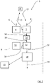
- the radar system 3 comprises a transceiver arrangement 8 that is arranged for generating and transmitting sweep signals in the form of FMCW (Frequency Modulated Continuous Wave) chirp signals 11, and to receive reflected signals 12, where the transmitted chirp signals 11 have been reflected such that a detection 14 that here is comprised in the work tool 5 is obtained.
- FMCW Frequency Modulated Continuous Wave
- the transceiver arrangement 8 comprises a transmitter arrangement 4 with a transmit antenna arrangement 6, a receiver arrangement 7 with a receiver antenna arrangement 9, an Analog to Digital Converter (ADC) arrangement 32 and sampling and timing arrangement 33.
- ADC Analog to Digital Converter
- the transmitted chirp signal 11 is in the form of a continuous sinusoid where the frequency varies from a first frequency f start to a second frequency f stop over the course of a ramp, where the magnitude of the first frequency f start falls below the magnitude of the second frequency f stop .
- the chirp signal 11 comprises repeating cycles of a plurality N of frequency ramps r where a radar cycle for the chirp signal 11 lasts for a certain radar cycle time t c , each ramp lasting a certain ramp time t r and where there is a certain delay time t D between adjacent ramps r.
- Each ramp r has a period time T that equals a sum of the ramp time t r and the delay time t D .
- the delay time t D can according to some aspects be essentially zero.
- the reflected signals 12 are received by the receiver arrangement 7 via the receiver antenna arrangement 9.
- the received signals 12, thus constituted by reflected radar echoes, are then mixed with the transmitted chirp signals 11 in the receiver arrangement 9.
- This may be a single channel mixer, or a two channel mixer comprising both in-phase and quadrature components.
- an IF (Intermediate Frequency) signal 34 is acquired, which may be real or, in the case of quadrature mixer, imaginary.
- the IF signal 34 is filtered in an IF filter 35 such that a filtered IF signal 36 is acquired.
- the frequency of the filtered IF signal 36 relates to the target distance and is transferred to the corresponding ADC arrangement 32, where the filtered IF signal 36 is sampled at a certain predetermined sampling frequency f s and converted to a digital IF signal 37 comprising sample points in a previously known manner, the sampling frequency f s being provided in the form of a sampling and timing signal 38 produced by the sampling and timing arrangement 33 that is connected to the ADC arrangement 32.
- the ADC arrangement 32 is connected to a DSP arrangement 39 that is adapted to execute an FFT (Fast Fourier Transform) processing of an FMCW radar signal to extract objects within the field of view 4.
- FFT Fast Fourier Transform
- a range FFT function is normally arranged to convert the filtered digital IF signal 36 to a range domain
- a Doppler FFT function is arranged to combine the results from successive chirp signal ramps, or other suitable Doppler radar cycles, into the Doppler domain.
- This results in an output 40 comprising Range-Doppler matrices that are transferred for further processing, which is not further discussed here, many examples of such further processing being well-known in the art. It is an object of the present disclosure to simplify said further processing.
- the radar system 3 also comprises a control unit 15.
- the control unit 15 should be regarded as a control unit arrangement that is in the form of one unit or several units that either co-operate or handle different tasks more or less independently. In the case of several units, these may be placed adjacent to each other, or in a distributed manner.
- the control unit is here shown connected to the DSP arrangement 39, of course this is not necessary; the control unit 15 may be connected to several components and/or other control units and can either comprise the DSP arrangement or be comprised in the DSP arrangement. In Figure 2 , the control unit 15 is shown outside the transceiver arrangement 8, but as understood from the above, this is not necessary.
- the transmitter antenna arrangement 6 when in use, sends a transmitted signal 11 when the vehicle 1 runs in the forward direction F.
- the radar system 3 then receives echoes of the transmitted signals 11 by means of the receiver antenna arrangement 9 where the transmitted signals 11 is reflected such that detections 14 are obtained; in Figure 1 a detection 14 is shown at the work tool 5.
- the above is repeated as many times as necessary at a predetermined frequency band, while the vehicle moves in the forward direction F.
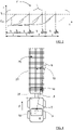
- each measure results in a detection 14, 25 (only two detections shown in Figure 4 for reasons of clarity), where the control unit 15 is arranged to use each detection 14, 25 to form a spectrum density map 30 for each radar cycle along the main field of view 4.
- the control unit 15 is thus arranged to combine at least two spectrum density maps to form a combined spectrum density map.
- a radar cycle is one observation phase in which the radar acquires data, processes the date on several signal processing levels and sends out available results. This can be a fixed time interval (i.e. 40 to 60 milliseconds), or it can be a dynamic time interval depending on environment conditions and processing load.
- the spectrum density map 30 comprises range and angle spectrum data.
- the spectrum density map 30 comprises a calculated returned amount of energy from stationary detections.
- the data comprised in the spectrum density map 30 may be taken from either the range FFT function or the Doppler FFT function.
- Each detection 14, 25 is thus detected several times as the vehicle 1 moves in the forward direction F during a plurality of sample times, where, at each sample time, detections 14, 25 within the field of view 4 are detected.
- a position is determined with respect to the ego vehicle 1, where the position is defined by a target distance T, running between the detection 14 and the vehicle radar system 3, and a target angle ⁇ running between a reference line 10, here running parallel to the forward direction F, and an extension 18 of the target distance T.
- a complete spectrum density map 30 is then acquired in a Cartesian grid and is combined from all radar cycles during a certain time, providing a dense estimation of energy returns 14, 25 instead of single separate detection points, where no dynamic data is needed for the spectrum density map 30.
- An energy return is any type of received reflection, for example from a detection 14 25. In this way, a two-dimensional detailed top view of the detections 14, 25 is obtained, where all energy returns are accounted for.
- the now acquired complete spectrum density map 30 it is possible to acquire information regarding zones where there is a large number of detections, or energy returns, and these zones are subject to analysis where it is determined whether these zones are to be disregarded or not, i.e. if it is determined whether these zones arise due to details mounted or connected to the ego vehicle 1 or not.
- a truck 1' is connected to a trailer 21 and comprises a radar system 3' that is rearward-looking.
- the trailer 21 will give rise to a zone that will be disregarded in the further processing of acquired radar data in the same manner as for the work vehicle 1 described above.
- the present disclosure also relates to a method for a vehicle FMCW (Frequency Modulated Continuous Wave) radar system 3 that is used in a vehicle 1, where the method comprises:
- the radar system may be implemented in any type of vehicle such as cars, trucks and buses as well as boats and aircraft.
- the constitution of the antenna devices comprised in the transmitter antenna arrangement 6 and the receiver antenna arrangement 9 may be of any suitable design, such as slot antennas of patch antennas.
- the transmitter antenna arrangement 6 and receiver antenna arrangement 9 may be combined in one antenna arrangement that is arranged for both transmission and reception by means of, for example, time division.
- the FMCW ramps can have any suitable shape such as saw-tooth or running from a higher frequency to a lower frequency, and are generally constituted by FMCW signals.
- the present disclosure relates to a vehicle FMCW (Frequency Modulated Continuous Wave) radar system 3 comprising a transmitter arrangement 4, a receiver arrangement 7 and at least one control unit 15, the radar system 3 being arranged to be mounted in a vehicle 1, where the radar system 3 is arranged to obtain a plurality of detections 14, 25 from the received reflected signals 12 along a main field of view 4 during at least two radar cycles where each radar cycle comprises a plurality of FMCW signals, where, for each radar cycle, said control unit 15 is arranged to form a spectrum density map 30 that comprises range and angle spectrum for each detection 14, 25 in a grid pattern 30 and to combine at least two spectrum density maps to form a combined spectrum density map. Said control unit 15 is arranged to determine that each part of the combined spectrum density map that has given rise to a reflected energy amount exceeding a certain threshold constitutes a zone 20 that is disregarded in further processing of acquired radar data.
- FMCW Frequency Modulated Continuous Wave
- said control unit 15 is arranged to calculate each spectrum density map 30 by means of either data from a range FFT (Fast Fourier Transform) function or a Doppler FFT function, where the radar system 3 comprises a DSP (Digital Signal Processor) function 39 that is arranged to perform said FFT functions.
- a range FFT Fast Fourier Transform
- a Doppler FFT function where the radar system 3 comprises a DSP (Digital Signal Processor) function 39 that is arranged to perform said FFT functions.
- said control unit 15 is arranged to perform an integration over a plurality of spectrum density maps 30 acquired during a certain number of radar cycles, and to select and group those detections 14 that have given rise to a reflected energy amount exceeding said certain threshold.
- the present disclosure also relates to a method for a vehicle FMCW (Frequency Modulated Continuous Wave) radar system 3 that is used in a vehicle 1, where the method comprises:
- each spectrum density map 30 is calculated by either using data from a range FFT (Fast Fourier Transform) function or using a Doppler FFT function.
- range FFT Fast Fourier Transform
- the method comprises:
Landscapes
- Engineering & Computer Science (AREA)
- Radar, Positioning & Navigation (AREA)
- Remote Sensing (AREA)
- Physics & Mathematics (AREA)
- Computer Networks & Wireless Communication (AREA)
- General Physics & Mathematics (AREA)
- Electromagnetism (AREA)
- Radar Systems Or Details Thereof (AREA)
Claims (6)
- Système radar FMCW, onde continue modulée en fréquence, pour véhicule (3) comprenant un arrangement de transmetteur (4), un arrangement de récepteur (7) et au moins une unité de commande (15), le système radar (3) étant arrangé pour être monté dans un véhicule (1), où le système radar (3) est arrangé pour obtenir une pluralité de détections (14, 25) de signaux réfléchis reçus (12) le long d'un champ de vision principal (4) durant au moins deux cycles radar où chaque cycle radar comprend une pluralité de signaux FMCW, où, pour chaque cycle radar, ladite unité de commande (15) est arrangée pour former une carte de densité spectrale (30) qui comprend un spectre de distance et d'angle pour chaque détection (14, 25) dans un quadrillage (30), ainsi qu'une quantité renvoyée calculée d'énergie réfléchie de détections stationnaires, et pour combiner au moins deux cartes de densité spectrale afin de former une carte de densité spectrale combinée de telle sorte que chaque point de grille dans le quadrillage (30) se rapporte à une pluralité de détections acquises et accumulées durant un certain temps,
dans lequel ladite unité de commande (15) est arrangée pour déterminer que chaque partie de la carte de densité spectrale combinée qui a donné lieu à une quantité d'énergie réfléchie dépassant un certain seuil constitue une zone (20) qui est ignorée dans un traitement ultérieur de données radar acquises. - Système radar selon la revendication 1, dans lequel ladite unité de commande (15) est arrangée pour calculer chaque carte de densité spectrale (30) au moyen soit de données d'une fonction FFT, transformée de Fourier accélérée, de distance, soit d'une fonction FFT du Doppler, où le système radar (3) comprend une fonction DSP, processeur de signaux numériques, (39) qui est arrangée pour exécuter lesdites fonctions FFT.
- Système radar selon l'une quelconque des revendications 1 ou 2, dans lequel ladite unité de commande (15) est arrangée pour exécuter une intégration sur la carte de densité spectrale combinée acquise, et pour sélectionner et grouper ces détections (14) qui ont donné lieu à une quantité d'énergie réfléchie dépassant un certain seuil.
- Procédé exécuté par un système radar FMCW, onde continue modulée en fréquence, (3) qui est utilisé dans un véhicule (1), où le procédé comprend :(42) transmettre des signaux (11) ;(43) recevoir des signaux réfléchis (12) ; et(44) obtenir une pluralité de détections (14, 25) de signaux réfléchis reçus (12) le long d'un champ de vision principal (4) durant au moins deux cycles radar, où chaque cycle radar comprend une pluralité de signaux FMCW,(45) pour chaque cycle radar, former une carte de densité spectrale (30) qui comprend un spectre de distance et d'angle pour chaque détection (14, 25) dans un quadrillage (30), ainsi qu'une quantité renvoyée calculée d'énergie réfléchie de détections stationnaires, en utilisant des détections (14, 25) le long du champ de vision principal (4) ; et(46) combiner au moins deux cartes de densité spectrale (30) pour former une carte de densité spectrale combinée de telle sorte que chaque point de grille dans le quadrillage (30) se rapporte à une pluralité de détections acquises et accumulées durant un certain temps ;où le procédé comprend en outre :
(47) déterminer que chaque partie de la carte de densité spectrale combinée qui a donné lieu à une quantité d'énergie réfléchie dépassant un certain seuil constitue une zone (20) qui est ignorée dans un traitement ultérieur de données radar acquises. - Procédé selon la revendication 4, dans lequel chaque carte de densité spectrale (30) est calculée soit en utilisant des données d'une fonction FFT, transformée de Fourier accélérée, de distance soit en utilisant une fonction FFT du Doppler.
- Procédé selon l'une quelconque des revendications 4 ou 5, où le procédé comprend :
exécuter une intégration sur la carte de densité spectrale combinée acquise, et sélectionner et grouper ces détections (14) qui ont donné lieu à une quantité d'énergie réfléchie dépassant un certain seuil permettant à une ou plusieurs zones (20) qui sont ignorées dans un traitement ultérieur de données radar acquises, d'être formées.
Priority Applications (1)
| Application Number | Priority Date | Filing Date | Title |
|---|---|---|---|
| EP17192368.3A EP3460512B1 (fr) | 2017-09-21 | 2017-09-21 | Radar de véhicule pour détection de l'environnement |
Applications Claiming Priority (1)
| Application Number | Priority Date | Filing Date | Title |
|---|---|---|---|
| EP17192368.3A EP3460512B1 (fr) | 2017-09-21 | 2017-09-21 | Radar de véhicule pour détection de l'environnement |
Publications (2)
| Publication Number | Publication Date |
|---|---|
| EP3460512A1 EP3460512A1 (fr) | 2019-03-27 |
| EP3460512B1 true EP3460512B1 (fr) | 2022-11-16 |
Family
ID=59930239
Family Applications (1)
| Application Number | Title | Priority Date | Filing Date |
|---|---|---|---|
| EP17192368.3A Active EP3460512B1 (fr) | 2017-09-21 | 2017-09-21 | Radar de véhicule pour détection de l'environnement |
Country Status (1)
| Country | Link |
|---|---|
| EP (1) | EP3460512B1 (fr) |
Families Citing this family (7)
| Publication number | Priority date | Publication date | Assignee | Title |
|---|---|---|---|---|
| EP3779505B1 (fr) | 2019-08-13 | 2024-06-12 | Magna Electronics Sweden AB | Détection de capteur radar bloqué |
| CN111208503B (zh) * | 2020-01-13 | 2022-04-01 | 佛山市云米电器科技有限公司 | 一种雷达定位方法及系统 |
| JP7363574B2 (ja) * | 2020-02-27 | 2023-10-18 | 株式会社デンソー | 物体検知装置 |
| CN111506084B (zh) * | 2020-05-19 | 2021-09-28 | 安徽江淮汽车集团股份有限公司 | 无人驾驶车辆的障碍物避让方法、装置、设备及存储介质 |
| JP7294256B2 (ja) * | 2020-07-03 | 2023-06-20 | トヨタ自動車株式会社 | レーザレーダ取付方法 |
| CN113835078B (zh) * | 2021-11-30 | 2022-03-04 | 中国电子科技集团公司信息科学研究院 | 基于局部三维栅格的信号级联合检测方法及装置 |
| DE102022201098A1 (de) | 2022-02-02 | 2023-08-03 | Robert Bosch Gesellschaft mit beschränkter Haftung | Verfahren, Recheneinheit und Computerprogramm zum Bestimmen von Umgebungsinformationen |
Family Cites Families (5)
| Publication number | Priority date | Publication date | Assignee | Title |
|---|---|---|---|---|
| US5587929A (en) * | 1994-09-02 | 1996-12-24 | Caterpillar Inc. | System and method for tracking objects using a detection system |
| DE102011101013A1 (de) * | 2011-05-10 | 2012-11-15 | Valeo Schalter Und Sensoren Gmbh | Verfahren zum Ausblenden eines irrelevanten Objektes beim Detektieren eines Hindernisses, Fahrerassistenzeinrichtung und Kraftfahrzeug |
| EP2755044A1 (fr) * | 2013-01-15 | 2014-07-16 | Autoliv Development AB | Auto-test radar fmcw |
| US9594155B2 (en) * | 2014-08-08 | 2017-03-14 | Delphi Technologies, Inc. | Vehicle radar system with trailer detection |
| US9784820B2 (en) * | 2014-09-19 | 2017-10-10 | Delphi Technologies, Inc. | Radar system with phase based multi-target detection |
-
2017
- 2017-09-21 EP EP17192368.3A patent/EP3460512B1/fr active Active
Also Published As
| Publication number | Publication date |
|---|---|
| EP3460512A1 (fr) | 2019-03-27 |
Similar Documents
| Publication | Publication Date | Title |
|---|---|---|
| EP3460512B1 (fr) | Radar de véhicule pour détection de l'environnement | |
| US9244164B2 (en) | Method for unambiguously determining a range and/or a relative speed of an object, driver assistance device and motor vehicle | |
| US11105919B2 (en) | Vehicle radar for environmental detection | |
| US11762084B2 (en) | Vehicle radar system | |
| US20160245911A1 (en) | 2-D Object Detection in Radar Applications | |
| EP2876460B1 (fr) | Radar de véhicule avec deux agencements d'antenne d'émetteur | |
| US11493596B2 (en) | Estimation of cartesian velocities of extended radar objects using a radar sensor | |
| EP4099056A1 (fr) | Système de radar de véhicule conçu pour réduire les interférences | |
| JP7257579B2 (ja) | 電子機器、電子機器の制御方法、及びプログラム | |
| US12000950B2 (en) | Estimation of transverse velocities or cartesian velocities of point targets with a radar sensor | |
| US11180137B2 (en) | Vehicle environmental detection system for parking detection | |
| KR20200120685A (ko) | 대형 안테나 어레이를 갖는 자동차용 레이더 센서의 각도 추정 및 모호정수 결정 | |
| US11650312B2 (en) | Method for determining at least one object information item of at least one target object which is sensed with a radar system, in particular of a vehicle, radar system and driver assistance system | |
| US20040140927A1 (en) | Length measurement with radar | |
| WO2023002870A1 (fr) | Dispositif électronique, procédé de commande de dispositif électronique et programme | |
| US20180267164A1 (en) | Close range filtering vehicle radar | |
| US11333754B2 (en) | Detection of parking row orientation | |
| KR102865505B1 (ko) | 차량의 레이더 장치 및 방법 | |
| GB2615297A (en) | Foreign object debris detection system | |
| US20240280692A1 (en) | Fine-near-range estimation method for automotive radar applications | |
| JP2023015894A (ja) | 電子機器、電子機器の制御方法、及びプログラム |
Legal Events
| Date | Code | Title | Description |
|---|---|---|---|
| PUAI | Public reference made under article 153(3) epc to a published international application that has entered the european phase |
Free format text: ORIGINAL CODE: 0009012 |
|
| STAA | Information on the status of an ep patent application or granted ep patent |
Free format text: STATUS: THE APPLICATION HAS BEEN PUBLISHED |
|
| AK | Designated contracting states |
Kind code of ref document: A1 Designated state(s): AL AT BE BG CH CY CZ DE DK EE ES FI FR GB GR HR HU IE IS IT LI LT LU LV MC MK MT NL NO PL PT RO RS SE SI SK SM TR |
|
| AX | Request for extension of the european patent |
Extension state: BA ME |
|
| STAA | Information on the status of an ep patent application or granted ep patent |
Free format text: STATUS: REQUEST FOR EXAMINATION WAS MADE |
|
| 17P | Request for examination filed |
Effective date: 20190920 |
|
| RBV | Designated contracting states (corrected) |
Designated state(s): AL AT BE BG CH CY CZ DE DK EE ES FI FR GB GR HR HU IE IS IT LI LT LU LV MC MK MT NL NO PL PT RO RS SE SI SK SM TR |
|
| STAA | Information on the status of an ep patent application or granted ep patent |
Free format text: STATUS: EXAMINATION IS IN PROGRESS |
|
| 17Q | First examination report despatched |
Effective date: 20210608 |
|
| GRAP | Despatch of communication of intention to grant a patent |
Free format text: ORIGINAL CODE: EPIDOSNIGR1 |
|
| STAA | Information on the status of an ep patent application or granted ep patent |
Free format text: STATUS: GRANT OF PATENT IS INTENDED |
|
| RIC1 | Information provided on ipc code assigned before grant |
Ipc: G01S 7/41 20060101ALI20220519BHEP Ipc: G01S 13/34 20060101ALI20220519BHEP Ipc: G01S 13/931 20200101ALI20220519BHEP Ipc: G01S 13/93 20060101ALI20220519BHEP Ipc: G01S 13/42 20060101AFI20220519BHEP |
|
| INTG | Intention to grant announced |
Effective date: 20220607 |
|
| RAP1 | Party data changed (applicant data changed or rights of an application transferred) |
Owner name: ARRIVER SOFTWARE AB |
|
| GRAS | Grant fee paid |
Free format text: ORIGINAL CODE: EPIDOSNIGR3 |
|
| GRAA | (expected) grant |
Free format text: ORIGINAL CODE: 0009210 |
|
| STAA | Information on the status of an ep patent application or granted ep patent |
Free format text: STATUS: THE PATENT HAS BEEN GRANTED |
|
| AK | Designated contracting states |
Kind code of ref document: B1 Designated state(s): AL AT BE BG CH CY CZ DE DK EE ES FI FR GB GR HR HU IE IS IT LI LT LU LV MC MK MT NL NO PL PT RO RS SE SI SK SM TR |
|
| REG | Reference to a national code |
Ref country code: GB Ref legal event code: FG4D |
|
| REG | Reference to a national code |
Ref country code: CH Ref legal event code: EP |
|
| REG | Reference to a national code |
Ref country code: IE Ref legal event code: FG4D |
|
| REG | Reference to a national code |
Ref country code: DE Ref legal event code: R096 Ref document number: 602017063683 Country of ref document: DE |
|
| REG | Reference to a national code |
Ref country code: AT Ref legal event code: REF Ref document number: 1532081 Country of ref document: AT Kind code of ref document: T Effective date: 20221215 |
|
| REG | Reference to a national code |
Ref country code: LT Ref legal event code: MG9D |
|
| REG | Reference to a national code |
Ref country code: NL Ref legal event code: MP Effective date: 20221116 |
|
| REG | Reference to a national code |
Ref country code: AT Ref legal event code: MK05 Ref document number: 1532081 Country of ref document: AT Kind code of ref document: T Effective date: 20221116 |
|
| PG25 | Lapsed in a contracting state [announced via postgrant information from national office to epo] |
Ref country code: SE Free format text: LAPSE BECAUSE OF FAILURE TO SUBMIT A TRANSLATION OF THE DESCRIPTION OR TO PAY THE FEE WITHIN THE PRESCRIBED TIME-LIMIT Effective date: 20221116 Ref country code: PT Free format text: LAPSE BECAUSE OF FAILURE TO SUBMIT A TRANSLATION OF THE DESCRIPTION OR TO PAY THE FEE WITHIN THE PRESCRIBED TIME-LIMIT Effective date: 20230316 Ref country code: NO Free format text: LAPSE BECAUSE OF FAILURE TO SUBMIT A TRANSLATION OF THE DESCRIPTION OR TO PAY THE FEE WITHIN THE PRESCRIBED TIME-LIMIT Effective date: 20230216 Ref country code: LT Free format text: LAPSE BECAUSE OF FAILURE TO SUBMIT A TRANSLATION OF THE DESCRIPTION OR TO PAY THE FEE WITHIN THE PRESCRIBED TIME-LIMIT Effective date: 20221116 Ref country code: FI Free format text: LAPSE BECAUSE OF FAILURE TO SUBMIT A TRANSLATION OF THE DESCRIPTION OR TO PAY THE FEE WITHIN THE PRESCRIBED TIME-LIMIT Effective date: 20221116 Ref country code: ES Free format text: LAPSE BECAUSE OF FAILURE TO SUBMIT A TRANSLATION OF THE DESCRIPTION OR TO PAY THE FEE WITHIN THE PRESCRIBED TIME-LIMIT Effective date: 20221116 Ref country code: AT Free format text: LAPSE BECAUSE OF FAILURE TO SUBMIT A TRANSLATION OF THE DESCRIPTION OR TO PAY THE FEE WITHIN THE PRESCRIBED TIME-LIMIT Effective date: 20221116 |
|
| PG25 | Lapsed in a contracting state [announced via postgrant information from national office to epo] |
Ref country code: RS Free format text: LAPSE BECAUSE OF FAILURE TO SUBMIT A TRANSLATION OF THE DESCRIPTION OR TO PAY THE FEE WITHIN THE PRESCRIBED TIME-LIMIT Effective date: 20221116 Ref country code: PL Free format text: LAPSE BECAUSE OF FAILURE TO SUBMIT A TRANSLATION OF THE DESCRIPTION OR TO PAY THE FEE WITHIN THE PRESCRIBED TIME-LIMIT Effective date: 20221116 Ref country code: LV Free format text: LAPSE BECAUSE OF FAILURE TO SUBMIT A TRANSLATION OF THE DESCRIPTION OR TO PAY THE FEE WITHIN THE PRESCRIBED TIME-LIMIT Effective date: 20221116 Ref country code: IS Free format text: LAPSE BECAUSE OF FAILURE TO SUBMIT A TRANSLATION OF THE DESCRIPTION OR TO PAY THE FEE WITHIN THE PRESCRIBED TIME-LIMIT Effective date: 20230316 Ref country code: HR Free format text: LAPSE BECAUSE OF FAILURE TO SUBMIT A TRANSLATION OF THE DESCRIPTION OR TO PAY THE FEE WITHIN THE PRESCRIBED TIME-LIMIT Effective date: 20221116 Ref country code: GR Free format text: LAPSE BECAUSE OF FAILURE TO SUBMIT A TRANSLATION OF THE DESCRIPTION OR TO PAY THE FEE WITHIN THE PRESCRIBED TIME-LIMIT Effective date: 20230217 |
|
| PG25 | Lapsed in a contracting state [announced via postgrant information from national office to epo] |
Ref country code: NL Free format text: LAPSE BECAUSE OF FAILURE TO SUBMIT A TRANSLATION OF THE DESCRIPTION OR TO PAY THE FEE WITHIN THE PRESCRIBED TIME-LIMIT Effective date: 20221116 |
|
| PG25 | Lapsed in a contracting state [announced via postgrant information from national office to epo] |
Ref country code: SM Free format text: LAPSE BECAUSE OF FAILURE TO SUBMIT A TRANSLATION OF THE DESCRIPTION OR TO PAY THE FEE WITHIN THE PRESCRIBED TIME-LIMIT Effective date: 20221116 Ref country code: RO Free format text: LAPSE BECAUSE OF FAILURE TO SUBMIT A TRANSLATION OF THE DESCRIPTION OR TO PAY THE FEE WITHIN THE PRESCRIBED TIME-LIMIT Effective date: 20221116 Ref country code: EE Free format text: LAPSE BECAUSE OF FAILURE TO SUBMIT A TRANSLATION OF THE DESCRIPTION OR TO PAY THE FEE WITHIN THE PRESCRIBED TIME-LIMIT Effective date: 20221116 Ref country code: DK Free format text: LAPSE BECAUSE OF FAILURE TO SUBMIT A TRANSLATION OF THE DESCRIPTION OR TO PAY THE FEE WITHIN THE PRESCRIBED TIME-LIMIT Effective date: 20221116 Ref country code: CZ Free format text: LAPSE BECAUSE OF FAILURE TO SUBMIT A TRANSLATION OF THE DESCRIPTION OR TO PAY THE FEE WITHIN THE PRESCRIBED TIME-LIMIT Effective date: 20221116 |
|
| REG | Reference to a national code |
Ref country code: DE Ref legal event code: R097 Ref document number: 602017063683 Country of ref document: DE |
|
| PG25 | Lapsed in a contracting state [announced via postgrant information from national office to epo] |
Ref country code: SK Free format text: LAPSE BECAUSE OF FAILURE TO SUBMIT A TRANSLATION OF THE DESCRIPTION OR TO PAY THE FEE WITHIN THE PRESCRIBED TIME-LIMIT Effective date: 20221116 Ref country code: AL Free format text: LAPSE BECAUSE OF FAILURE TO SUBMIT A TRANSLATION OF THE DESCRIPTION OR TO PAY THE FEE WITHIN THE PRESCRIBED TIME-LIMIT Effective date: 20221116 |
|
| PLBE | No opposition filed within time limit |
Free format text: ORIGINAL CODE: 0009261 |
|
| STAA | Information on the status of an ep patent application or granted ep patent |
Free format text: STATUS: NO OPPOSITION FILED WITHIN TIME LIMIT |
|
| 26N | No opposition filed |
Effective date: 20230817 |
|
| PG25 | Lapsed in a contracting state [announced via postgrant information from national office to epo] |
Ref country code: SI Free format text: LAPSE BECAUSE OF FAILURE TO SUBMIT A TRANSLATION OF THE DESCRIPTION OR TO PAY THE FEE WITHIN THE PRESCRIBED TIME-LIMIT Effective date: 20221116 |
|
| REG | Reference to a national code |
Ref country code: CH Ref legal event code: PL |
|
| PG25 | Lapsed in a contracting state [announced via postgrant information from national office to epo] |
Ref country code: LU Free format text: LAPSE BECAUSE OF NON-PAYMENT OF DUE FEES Effective date: 20230921 |
|
| REG | Reference to a national code |
Ref country code: BE Ref legal event code: MM Effective date: 20230930 |
|
| PG25 | Lapsed in a contracting state [announced via postgrant information from national office to epo] |
Ref country code: LU Free format text: LAPSE BECAUSE OF NON-PAYMENT OF DUE FEES Effective date: 20230921 Ref country code: IT Free format text: LAPSE BECAUSE OF FAILURE TO SUBMIT A TRANSLATION OF THE DESCRIPTION OR TO PAY THE FEE WITHIN THE PRESCRIBED TIME-LIMIT Effective date: 20221116 Ref country code: MC Free format text: LAPSE BECAUSE OF FAILURE TO SUBMIT A TRANSLATION OF THE DESCRIPTION OR TO PAY THE FEE WITHIN THE PRESCRIBED TIME-LIMIT Effective date: 20221116 |
|
| REG | Reference to a national code |
Ref country code: IE Ref legal event code: MM4A |
|
| PG25 | Lapsed in a contracting state [announced via postgrant information from national office to epo] |
Ref country code: IE Free format text: LAPSE BECAUSE OF NON-PAYMENT OF DUE FEES Effective date: 20230921 |
|
| PG25 | Lapsed in a contracting state [announced via postgrant information from national office to epo] |
Ref country code: CH Free format text: LAPSE BECAUSE OF NON-PAYMENT OF DUE FEES Effective date: 20230930 |
|
| PG25 | Lapsed in a contracting state [announced via postgrant information from national office to epo] |
Ref country code: IE Free format text: LAPSE BECAUSE OF NON-PAYMENT OF DUE FEES Effective date: 20230921 Ref country code: CH Free format text: LAPSE BECAUSE OF NON-PAYMENT OF DUE FEES Effective date: 20230930 |
|
| PG25 | Lapsed in a contracting state [announced via postgrant information from national office to epo] |
Ref country code: BE Free format text: LAPSE BECAUSE OF NON-PAYMENT OF DUE FEES Effective date: 20230930 |
|
| PG25 | Lapsed in a contracting state [announced via postgrant information from national office to epo] |
Ref country code: BG Free format text: LAPSE BECAUSE OF FAILURE TO SUBMIT A TRANSLATION OF THE DESCRIPTION OR TO PAY THE FEE WITHIN THE PRESCRIBED TIME-LIMIT Effective date: 20221116 |
|
| PG25 | Lapsed in a contracting state [announced via postgrant information from national office to epo] |
Ref country code: BG Free format text: LAPSE BECAUSE OF FAILURE TO SUBMIT A TRANSLATION OF THE DESCRIPTION OR TO PAY THE FEE WITHIN THE PRESCRIBED TIME-LIMIT Effective date: 20221116 |
|
| REG | Reference to a national code |
Ref country code: GB Ref legal event code: 732E Free format text: REGISTERED BETWEEN 20250206 AND 20250212 |
|
| REG | Reference to a national code |
Ref country code: DE Ref legal event code: R081 Ref document number: 602017063683 Country of ref document: DE Owner name: QUALCOMM AUTO LTD., GB Free format text: FORMER OWNER: ARRIVER SOFTWARE AB, LINKOEPING, SE |
|
| PG25 | Lapsed in a contracting state [announced via postgrant information from national office to epo] |
Ref country code: CY Free format text: LAPSE BECAUSE OF FAILURE TO SUBMIT A TRANSLATION OF THE DESCRIPTION OR TO PAY THE FEE WITHIN THE PRESCRIBED TIME-LIMIT; INVALID AB INITIO Effective date: 20170921 |
|
| PG25 | Lapsed in a contracting state [announced via postgrant information from national office to epo] |
Ref country code: HU Free format text: LAPSE BECAUSE OF FAILURE TO SUBMIT A TRANSLATION OF THE DESCRIPTION OR TO PAY THE FEE WITHIN THE PRESCRIBED TIME-LIMIT; INVALID AB INITIO Effective date: 20170921 |
|
| PGFP | Annual fee paid to national office [announced via postgrant information from national office to epo] |
Ref country code: DE Payment date: 20250808 Year of fee payment: 9 |
|
| PGFP | Annual fee paid to national office [announced via postgrant information from national office to epo] |
Ref country code: GB Payment date: 20250814 Year of fee payment: 9 |
|
| PGFP | Annual fee paid to national office [announced via postgrant information from national office to epo] |
Ref country code: FR Payment date: 20250808 Year of fee payment: 9 |
|
| PG25 | Lapsed in a contracting state [announced via postgrant information from national office to epo] |
Ref country code: TR Free format text: LAPSE BECAUSE OF FAILURE TO SUBMIT A TRANSLATION OF THE DESCRIPTION OR TO PAY THE FEE WITHIN THE PRESCRIBED TIME-LIMIT Effective date: 20221116 |