EP3460587A1 - Führungssystem - Google Patents
Führungssystem Download PDFInfo
- Publication number
- EP3460587A1 EP3460587A1 EP18195388.6A EP18195388A EP3460587A1 EP 3460587 A1 EP3460587 A1 EP 3460587A1 EP 18195388 A EP18195388 A EP 18195388A EP 3460587 A1 EP3460587 A1 EP 3460587A1
- Authority
- EP
- European Patent Office
- Prior art keywords
- slide
- slider
- path
- pins
- guide
- Prior art date
- Legal status (The legal status is an assumption and is not a legal conclusion. Google has not performed a legal analysis and makes no representation as to the accuracy of the status listed.)
- Granted
Links
Images

Classifications
-
- G—PHYSICS
- G04—HOROLOGY
- G04B—MECHANICALLY-DRIVEN CLOCKS OR WATCHES; MECHANICAL PARTS OF CLOCKS OR WATCHES IN GENERAL; TIME PIECES USING THE POSITION OF THE SUN, MOON OR STARS
- G04B19/00—Indicating the time by visual means
- G04B19/06—Dials
-
- G—PHYSICS
- G04—HOROLOGY
- G04B—MECHANICALLY-DRIVEN CLOCKS OR WATCHES; MECHANICAL PARTS OF CLOCKS OR WATCHES IN GENERAL; TIME PIECES USING THE POSITION OF THE SUN, MOON OR STARS
- G04B19/00—Indicating the time by visual means
- G04B19/02—Back-gearing arrangements between gear train and hands
-
- G—PHYSICS
- G04—HOROLOGY
- G04B—MECHANICALLY-DRIVEN CLOCKS OR WATCHES; MECHANICAL PARTS OF CLOCKS OR WATCHES IN GENERAL; TIME PIECES USING THE POSITION OF THE SUN, MOON OR STARS
- G04B19/00—Indicating the time by visual means
- G04B19/24—Clocks or watches with date or week-day indicators, i.e. calendar clocks or watches; Clockwork calendars
-
- G—PHYSICS
- G04—HOROLOGY
- G04B—MECHANICALLY-DRIVEN CLOCKS OR WATCHES; MECHANICAL PARTS OF CLOCKS OR WATCHES IN GENERAL; TIME PIECES USING THE POSITION OF THE SUN, MOON OR STARS
- G04B19/00—Indicating the time by visual means
- G04B19/26—Clocks or watches with indicators for tides, for the phases of the moon, or the like
- G04B19/262—Clocks or watches with indicators for tides, for the phases of the moon, or the like with indicators for astrological informations
-
- G—PHYSICS
- G04—HOROLOGY
- G04B—MECHANICALLY-DRIVEN CLOCKS OR WATCHES; MECHANICAL PARTS OF CLOCKS OR WATCHES IN GENERAL; TIME PIECES USING THE POSITION OF THE SUN, MOON OR STARS
- G04B45/00—Time pieces of which the indicating means or cases provoke special effects, e.g. aesthetic effects
- G04B45/0038—Figures or parts thereof moved by the clockwork
- G04B45/0061—Moving parts of the clockwork, e.g. pendulum, hands in special form, mostly constructed as a figure
Definitions
- the present invention relates to a guiding system for a timepiece, and a module for a timepiece comprising said system.
- Devices are known that make it possible to control the movement of an indicator on a watch face, for example the movement of a time indicator.
- the document US6809992 describes a watch where the hour hand moves in a closed circuit which is made in the form of two conchoid-type loops: an inner loop and an outer loop, the loops intersecting at a point of intersection.
- the loops are arranged in the dial of the watch.
- the needle is coupled to a rocker that moves in the groove to pass alternately from the outer loop to the inner loop and vice versa when the rocker reaches the point of intersection.
- the rocker comprises three wheels which are in permanent contact with the groove.
- the device does not include means for guiding the rocker in the groove, or to prevent the rocker is blocked at the point of intersection.
- WO2011160242 discloses a rotating bezel for a timepiece comprising a rotating guide piece at its center.
- the rotating part When the rotating part is actuated, it bears on sliding members positioned in a peripheral zone of the rotating part and causes their translation in a rectilinear groove, each member being arranged in a groove.
- the document EP3211487 describes a calculation mechanism for automatic movement.
- the mechanism comprises a wheel which carries a cam mounted on said wheel by a rail linear guide device.
- the rotation of the wheel causes the cam to rotate.
- the position of the cam is controlled by a cam control having a finger that fits into a groove of the cam.
- the movement further comprises a probe cooperating with the cam to guide the translation or pseudo translation of the cam.
- the document EP1953611 discloses a drive mechanism, for example a date mechanism, comprising a first correction member and a second correction member which act on the display device.
- the mechanism can adopt two positions: a position where it drives the display device when the first correction member is actuated; a second position where it is decoupled from the display device and the second correction member acts on the display device.
- the patent EP0509965 discloses a device comprising a half-wheel carrying a time indicator.
- the half-wheel is mounted on a slide which moves in translation and rotation in a groove.
- the half-wheel comprises two lugs with straight ends, the lugs inserting into a slide positioned in the extension of the groove: when the half-wheel is in translation, the lug of the half-wheel is housed in the slide for check the translation of the half-wheel.
- the device EP0509965 is also complex to assemble. There is a need for a simpler system.
- An object of the present invention is to provide a system free from the limitations of known guidance systems, or which minimizes these limitations.
- This solution has the advantage over the prior art of proposing a guidance system in which the displacement of a slider along a path is controlled in the three dimensions, that is to say in the plane (x, y) by a slide, and along the axis (z) perpendicular to the plane (x, y) thanks to the upper support element.
- the slider can bear directly against the upper support element, or through a damper, as will be seen.
- the system includes a slider along the path so that the guide pins slide in the slider that defines the path.
- the guide pins can be driven out or glued or otherwise secured to the slider.
- the guiding pins are integral with the slide.
- the guiding pins can be made integrally with the slide.
- the guiding pins may form a projection extending from the underside of the slider.
- the guiding pins are intended to be housed in the slide. When the guide pins are in the slide, their lateral displacement is limited by the contact between these pins and the walls of the slide. Thus, the guiding pins hold the slide along the path.
- the pins ensure the stability of the slider in particular in case of shocks.
- the presence of three pins also improves the reliability of the system by improving the accuracy of the movement of the slide in the slide.
- the three guiding pins are positioned on the vertices of a triangle.
- the guiding pins are movable with the slide. Instead of providing guide elements along the path, the guide pins move.
- the section of the slides can be in V.
- the distal end of the guide pins may be conical, the angle of the cone corresponding to the bottom angle of the slide.
- the distal end of the guide pins has a section of complementary shape to the section of the slide.
- the distal end of the guide pins may be ruby, or any other hard material ensuring a good coefficient of friction.
- the guide pin (s) may include a ruby portion on the distal end.
- the system also comprises an upper support element bearing against the slide to block the movement of the slide along the axis (z) perpendicular to the plane of movement of the slide.
- the slide is held between the slide and the support element, which guarantees the lateral stability of the slide in the plane (x, y) and transverse along the axis (z).
- the slide can be a closed or open loop.
- the slide may comprise rectilinear, curved, semicircular and / or circular portions.
- the slider is secured to an internal gear wheel, an internal gear half-wheel, or a rack, and driven by a pinion.
- the guide system comprises at least three pins. If there are four pins, they are positioned on the vertices of a square, a rectangle, or any other quadrilateral. The use of four pins is hyperstatic, but possibly improves the lateral stability of the slide.
- the slider carries a display member, for example a time indicator, a minute indicator, a second indicator, a calendar or a star indicator.
- the guidance system makes it possible to control the displacement of the display member, for example to follow a particular trajectory to a needle.
- the system of the invention can also be adapted to drive other indicators above or below the dial, for example to move a star in an elliptical orbit, or a calendar.
- the support element comprises a damper and a plate forming an upper bearing surface, the damper being compressed between the slide and the plate.
- the damper exerts a pressing force on the slide to press against the slide. It also makes it possible to compensate for any play and tolerance errors, and improves the system's resistance to shocks.
- the damper also has elastic properties, which makes it possible to damp the movement of the slide along the axis (z) in the event of shocks.
- the damper may be a compression spring, a coil spring, or a leaf spring.
- the upper support plate may be a dial.
- the upper support plate may be a guide plate under the dial.
- the upper support plate may be provided with a passage slot for the axis of a needle or for another indicator.
- the upper support plate may be ice.
- the slide is arranged in a support fixed on the movement stage or an additional module.
- the system comprises two slides along the trajectory.
- the slide comprises at least two guide pins, so that when the slide moves along the path, the pins move in the two slides simultaneously, each slide cooperating with at least one pin.
- the guide pins are housed in two slides.
- the two slides may comprise parallel portions, the spacing of the parallel portions then depends on the spacing of the pins on the slide.
- the system comprises a circular slide along the trajectory, the slide comprising at least three guide pins, for example positioned at the vertices of a triangle, so that when the slide moves along the trajectory said pins move simultaneously in the circular slideway.
- the slider is for example mounted on a wheel having an internal toothing, said wheel being actuated by a pinion which meshes with the toothing to drive the wheel in rotation.
- the rotation of the wheel causes the displacement of the pins of the slide in the slide.
- the trajectory is circular.
- the invention also relates to a timepiece module comprising at least one guide system according to the invention.
- the module is for example a movement.
- each system may be coupled to a different member, for example a first display member a second display member, said display members may be time indicators.
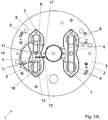
- the Figure 1A is a top view of the system with the 13 hour hand pointing at 3 o'clock; the Figure 1B illustrates the same system with the hour hand pointing to 1h.
- the system 1 illustrated in the figures is mounted on a plate 2 with a movement for a wristwatch (not shown) on the dial side 3.
- the plate 2 of this example comprises two guide systems 1, but for ease of reading, only a system 1 is detailed on the left side of the plate 2.
- the system 1 comprises a slider 4 which moves according to the trajectory defined by a slide 5.
- the slide 5 is arranged in a support 6 which is fixed on the plate 2.
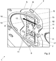
- the slide 5 here forms a closed loop, comprising two circular portions 7 connected by two rectilinear portions 8.
- the rectilinear portions 8 are parallel to each other and of the same length .
- the slide 5 is thus symmetrical with respect to a perpendicular axis (d) to the rectilinear portions 8 which passes in their environments.
- each rectilinear portion 8 intersects each circular portion 7 at two points of intersection 9: a portion of each rectilinear portion 8 is thus included in each circular portion 7.
- the slider 4 comprises a rectangular base. Guide pins 11 extend under the underside of this slider.
- the slider 4 comprises four guide pins 11 positioned at the four corners, so that the slider 4 rests on the four pins 11.
- the pins can be driven into openings through the slider, or secured by other means.
- the guide pins 11 are ruby, or in another hard material with a low coefficient of friction, for example ceramic. It is also possible to make guiding pins of which only the distal end accommodated in the slide 5 is ruby. This distal end may be formed by a ruby ball or ceramic. The ruby can be replaced by a carbon coating, for example of the DLC type.
- the slide carries an indicator.
- the indicator comprises a rod 12 which extends perpendicular to the plane of the slide 4. This rod 12 can pass through the support plate.
- the rod 12 carries a display member, here a needle 13, for example a hand hours, minutes or seconds.
- the dial 3 comprises two guiding systems 1: a system to the left of the dial to guide the movement of the hour hand and another system to the right of the dial to guide the movement of the minute hand, or vice versa.
- the system may comprise a damper (not shown in the figures), for example a leaf spring, compressed between the slide 4 and a support element, for example a plate provided for this purpose, the ice, a bridge or the face internal dial.
- a damper for example a leaf spring, compressed between the slide 4 and a support element, for example a plate provided for this purpose, the ice, a bridge or the face internal dial.
- This damper notably makes it possible to compensate for tolerance errors or gaps between the slide and the support element. It can be omitted; in this case, the upper face of the slider 4 slides directly under the support element.
- the upper face of the slide can be provided with other guide pins engaged in one or slides under the support element. This variant guarantees a very precise positioning, but requires a greater thickness.
- the displacement of the slider 4 along its trajectory is defined by the slide 5.
- this displacement comprises a translation and rotation movement.
- the slider 4 moves in translation in the rectilinear portions 8. Once the slider is at one end of the rectilinear portions 8, each guide pin 11 is on a point of intersection 9. In this position, the slider 4 can Rotate 180 °, then resume translational motion.
- the slider 4 is driven in the slide 5 by a pinion 14 which meshes with a half-wheel 15 integral with the slider and having an internal toothing 16.
- the pinion 14 is connected by kinematic links to a source of energy to actuate the rotation pinion 14: for example the pinion 14 is meshed on the movement of the wristwatch.
- the slider 4 is integral with the half-wheel 15.
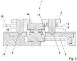
- two of the guide pins 11 are driven into the half-wheel 15, as shown in FIG. figure 3 , so that when the pinion 14 drives the half-wheel 15, the slider 4 is driven by the half-wheel 15.
- the half-wheel 14 comprises a straight segment 17 and a circular segment 18.
- the slide 4 moves in translation in the rectilinear portion 8 of the slide 5.
- the distance between the slide 4 and the ends of the straight segment 17 is calculated so that, when the pinion 4 arrives at one end of the straight segment 17, the guide pins 11 are at the points of intersection 9 of the slide 5.
- the pinion 14 meshes with the circular segment 18, which causes a progressive rotation of the slider 4: when the pinion 14 reaches the end of the circular segment 18, the slider has rotated 180 °. Then, the pinion 14 meshes again on the right segment 17 to resume a translation-rotation cycle. This arrangement allows the end of each needle to traverse an oval trajectory.
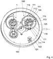
- the figure 4 represents a system 100 according to a second embodiment of the invention.
- the system 100 illustrated on the figure 4 is mounted on a plate 102 with a movement, said plate is covered with a dial 103.
- the plate 102 of this example comprises two guide systems 1,100 but for ease of reading, only a system 100 is detailed on the right side of the dial 103 because the system 1 (left of the dial) has already been described in the first embodiment.
- the system 100 comprises a slider 104 which moves along the path defined by a slider 105.
- the slider 105 is circular.
- the system 100 may comprise a damper (not shown in the figures), for example a leaf spring, compressed between the slide 104 and a support element, for example a plate provided for this purpose, ice, a bridge or the inner face of the dial.
- a damper for example a leaf spring, compressed between the slide 104 and a support element, for example a plate provided for this purpose, ice, a bridge or the inner face of the dial.
- the displacement of the slider 104 along its trajectory is defined by the slider 105.
- this displacement comprises a rotational movement centered on the slider 104.
- the slider 104 comprises a rectangular base. Guide pins 11 extend below the lower face of this slider 104.
- the slider 104 comprises four guide pins 111 positioned at the four corners, so that the slide 104 rests on the four pins 111.
- the slide 104 is driven in the slideway 105 by a pinion 114 which meshes with a wheel 115 integral with the slide and presenting An internal toothing 116.
- the pinion 114 is connected by kinematic links to a power source to actuate the rotation of the pinion 114: for example the pinion 114 is meshed with the movement of the wristwatch.
- the slider 104 is integral with the wheel 115.
- the slider 105 is aimed on a trolley with three branches 119, the end of each of the branches being fixed on the wheel 115.
- the slider 104 is secured to the wheel 115 through the carriage 119, so that when the pinion 114 drives the wheel 115, the slider 104 is driven by the wheel 115.
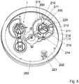
- the figure 5 represents a system 200 according to a third embodiment.
- the system 200 illustrated on the figure 5 is mounted on a plate 202 of a movement, said plate is covered with a dial 203.
- the plate 202 of this example comprises two guide systems 1, 200 but for ease of reading, only a system 200 is detailed on the part right of the dial 203 because the system 1 (left of the dial) has already been described in the first embodiment.
- the system 200 is identical to the system 100, except for the slider 204 and the pins 211.
- the slider 204 has a triangular base and is mounted on a carriage 219 with three branches spreading. Each branch of the slider 204 is driven into a branch of the carriage 219 by a pin 211, the slider 204 thus comprising three pins 211.
- the pins 211 of the slider 204 move in a circular slideway 205.
- the carriage 205 on which is fixed the slide 204, is mounted on a wheel 215 having an internal toothing 216.
- a pinion 214 meshes with the internal toothing 216 to drive the slide 204 in rotation about the central axis 220 passing through the center of the slider 204.
- the dial 103, 203 further comprises a window 121, 221 to display the day of the month.
Landscapes
- Physics & Mathematics (AREA)
- General Physics & Mathematics (AREA)
- Astronomy & Astrophysics (AREA)
- Electromechanical Clocks (AREA)
- Electric Clocks (AREA)
Applications Claiming Priority (1)
| Application Number | Priority Date | Filing Date | Title |
|---|---|---|---|
| CH01155/17A CH714177A1 (fr) | 2017-09-20 | 2017-09-20 | Système de guidage pour pièce d'horlogerie. |
Publications (2)
| Publication Number | Publication Date |
|---|---|
| EP3460587A1 true EP3460587A1 (de) | 2019-03-27 |
| EP3460587B1 EP3460587B1 (de) | 2021-04-21 |
Family
ID=61022068
Family Applications (1)
| Application Number | Title | Priority Date | Filing Date |
|---|---|---|---|
| EP18195388.6A Active EP3460587B1 (de) | 2017-09-20 | 2018-09-19 | Führungssystem |
Country Status (4)
| Country | Link |
|---|---|
| US (1) | US20190086869A1 (de) |
| EP (1) | EP3460587B1 (de) |
| JP (1) | JP6716653B2 (de) |
| CH (1) | CH714177A1 (de) |
Citations (4)
| Publication number | Priority date | Publication date | Assignee | Title |
|---|---|---|---|---|
| EP0509965A1 (de) * | 1991-03-27 | 1992-10-21 | Carlo Ferrara | Antriebvorrichtung für Uhr- oder Pendeluhrzeiger |
| EP1953611A1 (de) * | 2007-01-30 | 2008-08-06 | Compagnie des Montres Longines, Francillon SA | Uhr, die einen Antriebsmechanismus einer Vorrichtung zur Anzeige einer mit der Zeit zusammenhängenden Größe umfasst |
| WO2011160242A1 (fr) * | 2010-06-23 | 2011-12-29 | Pierre-Alain Storrer | Lunette tournante pour piece d'horlogerie |
| EP3211487A1 (de) * | 2016-02-04 | 2017-08-30 | Krayon Sarl | Vorrichtung für berechnungsmechanismus von astronomischen phänomenen |
Family Cites Families (3)
| Publication number | Priority date | Publication date | Assignee | Title |
|---|---|---|---|---|
| US5177713A (en) * | 1991-06-10 | 1993-01-05 | Doughty Edwin J | Motorized slide stick calendar |
| JPH06222161A (ja) * | 1993-01-22 | 1994-08-12 | Seikosha Co Ltd | 文字板開閉式時計 |
| US7515508B1 (en) * | 2008-03-12 | 2009-04-07 | Timex Group B.V. | Indicator assembly for a wearable electronic device |
-
2017
- 2017-09-20 CH CH01155/17A patent/CH714177A1/fr unknown
-
2018
- 2018-09-18 US US16/134,402 patent/US20190086869A1/en not_active Abandoned
- 2018-09-19 EP EP18195388.6A patent/EP3460587B1/de active Active
- 2018-09-19 JP JP2018174431A patent/JP6716653B2/ja active Active
Patent Citations (4)
| Publication number | Priority date | Publication date | Assignee | Title |
|---|---|---|---|---|
| EP0509965A1 (de) * | 1991-03-27 | 1992-10-21 | Carlo Ferrara | Antriebvorrichtung für Uhr- oder Pendeluhrzeiger |
| EP1953611A1 (de) * | 2007-01-30 | 2008-08-06 | Compagnie des Montres Longines, Francillon SA | Uhr, die einen Antriebsmechanismus einer Vorrichtung zur Anzeige einer mit der Zeit zusammenhängenden Größe umfasst |
| WO2011160242A1 (fr) * | 2010-06-23 | 2011-12-29 | Pierre-Alain Storrer | Lunette tournante pour piece d'horlogerie |
| EP3211487A1 (de) * | 2016-02-04 | 2017-08-30 | Krayon Sarl | Vorrichtung für berechnungsmechanismus von astronomischen phänomenen |
Also Published As
| Publication number | Publication date |
|---|---|
| EP3460587B1 (de) | 2021-04-21 |
| US20190086869A1 (en) | 2019-03-21 |
| JP2019056703A (ja) | 2019-04-11 |
| CH714177A1 (fr) | 2019-03-29 |
| JP6716653B2 (ja) | 2020-07-01 |
Similar Documents
| Publication | Publication Date | Title |
|---|---|---|
| EP2233988B1 (de) | Uhrwerk mit Tourbillon, das mit einer stoßfesten Schutzvorrichtung ausgestattet ist | |
| EP2273323A2 (de) | Mechanischer Oszillator | |
| EP3382470A1 (de) | Oszillator einer uhr mit flexiblem zapfen | |
| EP3172626A1 (de) | Biegeachszapfen | |
| EP2813903A1 (de) | Mechanische Einstellung des Lagerspiels eines Uhrwerk-Zahnrads | |
| WO2019175687A1 (fr) | Pièce d'horlogerie | |
| EP3460587B1 (de) | Führungssystem | |
| EP2798414B1 (de) | Feder für uhrwerk | |
| EP2781971B1 (de) | Struktur für Uhrwerksmechanismus | |
| CH713209B1 (fr) | Mécanisme d'affichage pour pièce d'horlogerie. | |
| EP2884345B1 (de) | Hebelfeder für uhrwerk | |
| CH713787A2 (fr) | Dispositif horloger à organe de positionnement. | |
| CH715052A2 (fr) | Mécanisme à couple constant, mouvement de pièce d'horlogerie, et pièce d'horlogerie. | |
| WO2019092664A1 (fr) | Organe moteur d'horlogerie. | |
| EP4428625A1 (de) | Vorrichtung zur autonomen einstellung der aktiven länge einer spiralfeder | |
| CH716774B1 (fr) | Dispositif horloger de couplage et d'indexation. | |
| EP3399373A1 (de) | Uhrvorrichtung mit positionierorgan | |
| EP2112566A1 (de) | Analoge Anzeigevorrichtung insbesondere für eine Uhr | |
| EP3629100B1 (de) | Vorrichtung zur symmetrischen führung von zwei elementen, insbesondere für uhrwerke | |
| EP3714336B1 (de) | Halterung eines mobilgeräts mit einer anzeigescheibe | |
| EP1791041A1 (de) | Uhrwerk | |
| CH720584A2 (fr) | Dispositif de réglage autonome de la longueur active d'un spiral | |
| CH708161B1 (fr) | Mouvement comportant des moyens de réglage mécanique de l'ébat d'un mobile d'horlogerie. | |
| CH709181B1 (fr) | Pièce d'horlogerie comprenant un dispositif d'animation. | |
| CH719047A2 (fr) | Mécanisme d'entraînement discontinu d'horlogerie. |
Legal Events
| Date | Code | Title | Description |
|---|---|---|---|
| PUAI | Public reference made under article 153(3) epc to a published international application that has entered the european phase |
Free format text: ORIGINAL CODE: 0009012 |
|
| STAA | Information on the status of an ep patent application or granted ep patent |
Free format text: STATUS: THE APPLICATION HAS BEEN PUBLISHED |
|
| AK | Designated contracting states |
Kind code of ref document: A1 Designated state(s): AL AT BE BG CH CY CZ DE DK EE ES FI FR GB GR HR HU IE IS IT LI LT LU LV MC MK MT NL NO PL PT RO RS SE SI SK SM TR |
|
| AX | Request for extension of the european patent |
Extension state: BA ME |
|
| STAA | Information on the status of an ep patent application or granted ep patent |
Free format text: STATUS: REQUEST FOR EXAMINATION WAS MADE |
|
| 17P | Request for examination filed |
Effective date: 20190702 |
|
| RBV | Designated contracting states (corrected) |
Designated state(s): AL AT BE BG CH CY CZ DE DK EE ES FI FR GB GR HR HU IE IS IT LI LT LU LV MC MK MT NL NO PL PT RO RS SE SI SK SM TR |
|
| STAA | Information on the status of an ep patent application or granted ep patent |
Free format text: STATUS: EXAMINATION IS IN PROGRESS |
|
| 17Q | First examination report despatched |
Effective date: 20200331 |
|
| GRAP | Despatch of communication of intention to grant a patent |
Free format text: ORIGINAL CODE: EPIDOSNIGR1 |
|
| STAA | Information on the status of an ep patent application or granted ep patent |
Free format text: STATUS: GRANT OF PATENT IS INTENDED |
|
| INTG | Intention to grant announced |
Effective date: 20201203 |
|
| RIN1 | Information on inventor provided before grant (corrected) |
Inventor name: VOUMARD, MARTIAL |
|
| GRAS | Grant fee paid |
Free format text: ORIGINAL CODE: EPIDOSNIGR3 |
|
| GRAA | (expected) grant |
Free format text: ORIGINAL CODE: 0009210 |
|
| STAA | Information on the status of an ep patent application or granted ep patent |
Free format text: STATUS: THE PATENT HAS BEEN GRANTED |
|
| AK | Designated contracting states |
Kind code of ref document: B1 Designated state(s): AL AT BE BG CH CY CZ DE DK EE ES FI FR GB GR HR HU IE IS IT LI LT LU LV MC MK MT NL NO PL PT RO RS SE SI SK SM TR |
|
| REG | Reference to a national code |
Ref country code: GB Ref legal event code: FG4D Free format text: NOT ENGLISH |
|
| REG | Reference to a national code |
Ref country code: CH Ref legal event code: EP Ref country code: CH Ref legal event code: NV Representative=s name: P&TS SA, CH |
|
| REG | Reference to a national code |
Ref country code: DE Ref legal event code: R096 Ref document number: 602018015770 Country of ref document: DE |
|
| REG | Reference to a national code |
Ref country code: IE Ref legal event code: FG4D Free format text: LANGUAGE OF EP DOCUMENT: FRENCH |
|
| REG | Reference to a national code |
Ref country code: AT Ref legal event code: REF Ref document number: 1385293 Country of ref document: AT Kind code of ref document: T Effective date: 20210515 |
|
| REG | Reference to a national code |
Ref country code: LT Ref legal event code: MG9D |
|
| REG | Reference to a national code |
Ref country code: AT Ref legal event code: MK05 Ref document number: 1385293 Country of ref document: AT Kind code of ref document: T Effective date: 20210421 |
|
| REG | Reference to a national code |
Ref country code: NL Ref legal event code: MP Effective date: 20210421 |
|
| PG25 | Lapsed in a contracting state [announced via postgrant information from national office to epo] |
Ref country code: HR Free format text: LAPSE BECAUSE OF FAILURE TO SUBMIT A TRANSLATION OF THE DESCRIPTION OR TO PAY THE FEE WITHIN THE PRESCRIBED TIME-LIMIT Effective date: 20210421 Ref country code: LT Free format text: LAPSE BECAUSE OF FAILURE TO SUBMIT A TRANSLATION OF THE DESCRIPTION OR TO PAY THE FEE WITHIN THE PRESCRIBED TIME-LIMIT Effective date: 20210421 Ref country code: FI Free format text: LAPSE BECAUSE OF FAILURE TO SUBMIT A TRANSLATION OF THE DESCRIPTION OR TO PAY THE FEE WITHIN THE PRESCRIBED TIME-LIMIT Effective date: 20210421 Ref country code: AT Free format text: LAPSE BECAUSE OF FAILURE TO SUBMIT A TRANSLATION OF THE DESCRIPTION OR TO PAY THE FEE WITHIN THE PRESCRIBED TIME-LIMIT Effective date: 20210421 Ref country code: BG Free format text: LAPSE BECAUSE OF FAILURE TO SUBMIT A TRANSLATION OF THE DESCRIPTION OR TO PAY THE FEE WITHIN THE PRESCRIBED TIME-LIMIT Effective date: 20210721 Ref country code: NL Free format text: LAPSE BECAUSE OF FAILURE TO SUBMIT A TRANSLATION OF THE DESCRIPTION OR TO PAY THE FEE WITHIN THE PRESCRIBED TIME-LIMIT Effective date: 20210421 |
|
| PG25 | Lapsed in a contracting state [announced via postgrant information from national office to epo] |
Ref country code: RS Free format text: LAPSE BECAUSE OF FAILURE TO SUBMIT A TRANSLATION OF THE DESCRIPTION OR TO PAY THE FEE WITHIN THE PRESCRIBED TIME-LIMIT Effective date: 20210421 Ref country code: SE Free format text: LAPSE BECAUSE OF FAILURE TO SUBMIT A TRANSLATION OF THE DESCRIPTION OR TO PAY THE FEE WITHIN THE PRESCRIBED TIME-LIMIT Effective date: 20210421 Ref country code: LV Free format text: LAPSE BECAUSE OF FAILURE TO SUBMIT A TRANSLATION OF THE DESCRIPTION OR TO PAY THE FEE WITHIN THE PRESCRIBED TIME-LIMIT Effective date: 20210421 Ref country code: PT Free format text: LAPSE BECAUSE OF FAILURE TO SUBMIT A TRANSLATION OF THE DESCRIPTION OR TO PAY THE FEE WITHIN THE PRESCRIBED TIME-LIMIT Effective date: 20210823 Ref country code: PL Free format text: LAPSE BECAUSE OF FAILURE TO SUBMIT A TRANSLATION OF THE DESCRIPTION OR TO PAY THE FEE WITHIN THE PRESCRIBED TIME-LIMIT Effective date: 20210421 Ref country code: NO Free format text: LAPSE BECAUSE OF FAILURE TO SUBMIT A TRANSLATION OF THE DESCRIPTION OR TO PAY THE FEE WITHIN THE PRESCRIBED TIME-LIMIT Effective date: 20210721 Ref country code: IS Free format text: LAPSE BECAUSE OF FAILURE TO SUBMIT A TRANSLATION OF THE DESCRIPTION OR TO PAY THE FEE WITHIN THE PRESCRIBED TIME-LIMIT Effective date: 20210821 Ref country code: GR Free format text: LAPSE BECAUSE OF FAILURE TO SUBMIT A TRANSLATION OF THE DESCRIPTION OR TO PAY THE FEE WITHIN THE PRESCRIBED TIME-LIMIT Effective date: 20210722 |
|
| REG | Reference to a national code |
Ref country code: DE Ref legal event code: R097 Ref document number: 602018015770 Country of ref document: DE |
|
| PG25 | Lapsed in a contracting state [announced via postgrant information from national office to epo] |
Ref country code: SM Free format text: LAPSE BECAUSE OF FAILURE TO SUBMIT A TRANSLATION OF THE DESCRIPTION OR TO PAY THE FEE WITHIN THE PRESCRIBED TIME-LIMIT Effective date: 20210421 Ref country code: SK Free format text: LAPSE BECAUSE OF FAILURE TO SUBMIT A TRANSLATION OF THE DESCRIPTION OR TO PAY THE FEE WITHIN THE PRESCRIBED TIME-LIMIT Effective date: 20210421 Ref country code: EE Free format text: LAPSE BECAUSE OF FAILURE TO SUBMIT A TRANSLATION OF THE DESCRIPTION OR TO PAY THE FEE WITHIN THE PRESCRIBED TIME-LIMIT Effective date: 20210421 Ref country code: ES Free format text: LAPSE BECAUSE OF FAILURE TO SUBMIT A TRANSLATION OF THE DESCRIPTION OR TO PAY THE FEE WITHIN THE PRESCRIBED TIME-LIMIT Effective date: 20210421 Ref country code: DK Free format text: LAPSE BECAUSE OF FAILURE TO SUBMIT A TRANSLATION OF THE DESCRIPTION OR TO PAY THE FEE WITHIN THE PRESCRIBED TIME-LIMIT Effective date: 20210421 Ref country code: CZ Free format text: LAPSE BECAUSE OF FAILURE TO SUBMIT A TRANSLATION OF THE DESCRIPTION OR TO PAY THE FEE WITHIN THE PRESCRIBED TIME-LIMIT Effective date: 20210421 Ref country code: RO Free format text: LAPSE BECAUSE OF FAILURE TO SUBMIT A TRANSLATION OF THE DESCRIPTION OR TO PAY THE FEE WITHIN THE PRESCRIBED TIME-LIMIT Effective date: 20210421 |
|
| PLBE | No opposition filed within time limit |
Free format text: ORIGINAL CODE: 0009261 |
|
| STAA | Information on the status of an ep patent application or granted ep patent |
Free format text: STATUS: NO OPPOSITION FILED WITHIN TIME LIMIT |
|
| 26N | No opposition filed |
Effective date: 20220124 |
|
| REG | Reference to a national code |
Ref country code: BE Ref legal event code: MM Effective date: 20210930 |
|
| PG25 | Lapsed in a contracting state [announced via postgrant information from national office to epo] |
Ref country code: IS Free format text: LAPSE BECAUSE OF FAILURE TO SUBMIT A TRANSLATION OF THE DESCRIPTION OR TO PAY THE FEE WITHIN THE PRESCRIBED TIME-LIMIT Effective date: 20210821 Ref country code: MC Free format text: LAPSE BECAUSE OF FAILURE TO SUBMIT A TRANSLATION OF THE DESCRIPTION OR TO PAY THE FEE WITHIN THE PRESCRIBED TIME-LIMIT Effective date: 20210421 Ref country code: AL Free format text: LAPSE BECAUSE OF FAILURE TO SUBMIT A TRANSLATION OF THE DESCRIPTION OR TO PAY THE FEE WITHIN THE PRESCRIBED TIME-LIMIT Effective date: 20210421 |
|
| PG25 | Lapsed in a contracting state [announced via postgrant information from national office to epo] |
Ref country code: LU Free format text: LAPSE BECAUSE OF NON-PAYMENT OF DUE FEES Effective date: 20210919 Ref country code: IT Free format text: LAPSE BECAUSE OF FAILURE TO SUBMIT A TRANSLATION OF THE DESCRIPTION OR TO PAY THE FEE WITHIN THE PRESCRIBED TIME-LIMIT Effective date: 20210421 Ref country code: IE Free format text: LAPSE BECAUSE OF NON-PAYMENT OF DUE FEES Effective date: 20210919 Ref country code: BE Free format text: LAPSE BECAUSE OF NON-PAYMENT OF DUE FEES Effective date: 20210930 |
|
| GBPC | Gb: european patent ceased through non-payment of renewal fee |
Effective date: 20220919 |
|
| PG25 | Lapsed in a contracting state [announced via postgrant information from national office to epo] |
Ref country code: CY Free format text: LAPSE BECAUSE OF FAILURE TO SUBMIT A TRANSLATION OF THE DESCRIPTION OR TO PAY THE FEE WITHIN THE PRESCRIBED TIME-LIMIT Effective date: 20210421 |
|
| PG25 | Lapsed in a contracting state [announced via postgrant information from national office to epo] |
Ref country code: HU Free format text: LAPSE BECAUSE OF FAILURE TO SUBMIT A TRANSLATION OF THE DESCRIPTION OR TO PAY THE FEE WITHIN THE PRESCRIBED TIME-LIMIT; INVALID AB INITIO Effective date: 20180919 |
|
| PG25 | Lapsed in a contracting state [announced via postgrant information from national office to epo] |
Ref country code: GB Free format text: LAPSE BECAUSE OF NON-PAYMENT OF DUE FEES Effective date: 20220919 |
|
| PG25 | Lapsed in a contracting state [announced via postgrant information from national office to epo] |
Ref country code: MK Free format text: LAPSE BECAUSE OF FAILURE TO SUBMIT A TRANSLATION OF THE DESCRIPTION OR TO PAY THE FEE WITHIN THE PRESCRIBED TIME-LIMIT Effective date: 20210421 |
|
| PG25 | Lapsed in a contracting state [announced via postgrant information from national office to epo] |
Ref country code: MT Free format text: LAPSE BECAUSE OF FAILURE TO SUBMIT A TRANSLATION OF THE DESCRIPTION OR TO PAY THE FEE WITHIN THE PRESCRIBED TIME-LIMIT Effective date: 20210421 |
|
| REG | Reference to a national code |
Ref country code: CH Ref legal event code: U11 Free format text: ST27 STATUS EVENT CODE: U-0-0-U10-U11 (AS PROVIDED BY THE NATIONAL OFFICE) Effective date: 20251001 |
|
| PGFP | Annual fee paid to national office [announced via postgrant information from national office to epo] |
Ref country code: DE Payment date: 20250919 Year of fee payment: 8 |
|
| PGFP | Annual fee paid to national office [announced via postgrant information from national office to epo] |
Ref country code: FR Payment date: 20250922 Year of fee payment: 8 |
|
| PG25 | Lapsed in a contracting state [announced via postgrant information from national office to epo] |
Ref country code: TR Free format text: LAPSE BECAUSE OF FAILURE TO SUBMIT A TRANSLATION OF THE DESCRIPTION OR TO PAY THE FEE WITHIN THE PRESCRIBED TIME-LIMIT Effective date: 20210421 |
|
| PGFP | Annual fee paid to national office [announced via postgrant information from national office to epo] |
Ref country code: CH Payment date: 20251001 Year of fee payment: 8 |