EP3460754B1 - Procédé de mesure d'image, programme de mesure d'image, dispositif de mesure d'image et procédé de fabrication d'objet - Google Patents
Procédé de mesure d'image, programme de mesure d'image, dispositif de mesure d'image et procédé de fabrication d'objet Download PDFInfo
- Publication number
- EP3460754B1 EP3460754B1 EP16899483.8A EP16899483A EP3460754B1 EP 3460754 B1 EP3460754 B1 EP 3460754B1 EP 16899483 A EP16899483 A EP 16899483A EP 3460754 B1 EP3460754 B1 EP 3460754B1
- Authority
- EP
- European Patent Office
- Prior art keywords
- measurement
- candidate
- related information
- geometric
- shape
- Prior art date
- Legal status (The legal status is an assumption and is not a legal conclusion. Google has not performed a legal analysis and makes no representation as to the accuracy of the status listed.)
- Active
Links
Images













Classifications
-
- G—PHYSICS
- G06—COMPUTING OR CALCULATING; COUNTING
- G06T—IMAGE DATA PROCESSING OR GENERATION, IN GENERAL
- G06T7/00—Image analysis
- G06T7/60—Analysis of geometric attributes
-
- G—PHYSICS
- G01—MEASURING; TESTING
- G01B—MEASURING LENGTH, THICKNESS OR SIMILAR LINEAR DIMENSIONS; MEASURING ANGLES; MEASURING AREAS; MEASURING IRREGULARITIES OF SURFACES OR CONTOURS
- G01B11/00—Measuring arrangements characterised by the use of optical techniques
- G01B11/02—Measuring arrangements characterised by the use of optical techniques for measuring length, width or thickness
- G01B11/022—Measuring arrangements characterised by the use of optical techniques for measuring length, width or thickness by means of tv-camera scanning
-
- G—PHYSICS
- G01—MEASURING; TESTING
- G01B—MEASURING LENGTH, THICKNESS OR SIMILAR LINEAR DIMENSIONS; MEASURING ANGLES; MEASURING AREAS; MEASURING IRREGULARITIES OF SURFACES OR CONTOURS
- G01B11/00—Measuring arrangements characterised by the use of optical techniques
- G01B11/02—Measuring arrangements characterised by the use of optical techniques for measuring length, width or thickness
-
- G—PHYSICS
- G01—MEASURING; TESTING
- G01B—MEASURING LENGTH, THICKNESS OR SIMILAR LINEAR DIMENSIONS; MEASURING ANGLES; MEASURING AREAS; MEASURING IRREGULARITIES OF SURFACES OR CONTOURS
- G01B11/00—Measuring arrangements characterised by the use of optical techniques
- G01B11/24—Measuring arrangements characterised by the use of optical techniques for measuring contours or curvatures
-
- G—PHYSICS
- G06—COMPUTING OR CALCULATING; COUNTING
- G06T—IMAGE DATA PROCESSING OR GENERATION, IN GENERAL
- G06T7/00—Image analysis
- G06T7/0002—Inspection of images, e.g. flaw detection
- G06T7/0004—Industrial image inspection
-
- G—PHYSICS
- G06—COMPUTING OR CALCULATING; COUNTING
- G06T—IMAGE DATA PROCESSING OR GENERATION, IN GENERAL
- G06T7/00—Image analysis
- G06T7/0002—Inspection of images, e.g. flaw detection
- G06T7/0004—Industrial image inspection
- G06T7/0006—Industrial image inspection using a design-rule based approach
-
- G—PHYSICS
- G06—COMPUTING OR CALCULATING; COUNTING
- G06T—IMAGE DATA PROCESSING OR GENERATION, IN GENERAL
- G06T7/00—Image analysis
- G06T7/50—Depth or shape recovery
-
- G—PHYSICS
- G06—COMPUTING OR CALCULATING; COUNTING
- G06T—IMAGE DATA PROCESSING OR GENERATION, IN GENERAL
- G06T7/00—Image analysis
- G06T7/60—Analysis of geometric attributes
- G06T7/62—Analysis of geometric attributes of area, perimeter, diameter or volume
-
- G—PHYSICS
- G06—COMPUTING OR CALCULATING; COUNTING
- G06T—IMAGE DATA PROCESSING OR GENERATION, IN GENERAL
- G06T2200/00—Indexing scheme for image data processing or generation, in general
- G06T2200/24—Indexing scheme for image data processing or generation, in general involving graphical user interfaces [GUIs]
-
- G—PHYSICS
- G06—COMPUTING OR CALCULATING; COUNTING
- G06T—IMAGE DATA PROCESSING OR GENERATION, IN GENERAL
- G06T2207/00—Indexing scheme for image analysis or image enhancement
- G06T2207/20—Special algorithmic details
- G06T2207/20092—Interactive image processing based on input by user
- G06T2207/20096—Interactive definition of curve of interest
-
- G—PHYSICS
- G06—COMPUTING OR CALCULATING; COUNTING
- G06T—IMAGE DATA PROCESSING OR GENERATION, IN GENERAL
- G06T2207/00—Indexing scheme for image analysis or image enhancement
- G06T2207/30—Subject of image; Context of image processing
- G06T2207/30108—Industrial image inspection
- G06T2207/30164—Workpiece; Machine component
Definitions
- the present invention relates to an image measurement method, an image measurement program, an image measurement device, and a method for manufacturing an object.
- An image measurement device used in the industrial field and the like displays an image of a measurement target acquired by image capturing on a display screen, also executes a geometric shape included in the image of the measurement target, and then performs measurement processing related to the extracted geometric shape (for example, see US Patent Application No. 2014/0005978 , hereinafter Patent Document 1).
- JP2015 114875 A US 2010/189308 A1 , EP 2 557 538 A2 , and JP H11 257923 A
- the operation for a measurement has required a lot of time and effort, and usability for a user has been poor.
- the present invention has been made in view of the aforementioned problems, and an object thereof is to provide an image measurement method, an image measurement program, and an image measurement device being capable of improving usability, and a method for manufacturing an object being capable of simplifying operation.
- an image measurement device as recited in claim 22 below.
- An image measurement method, an image measurement program, and an image measurement device of the present invention achieve the effect capable of improving usability. Further, a method for manufacturing an object of the present invention achieves the effect capable of simplifying operation.
- FIG. 1 schematically illustrates a configuration of an image measurement device 100 according to the first embodiment.
- the image measurement device 100 includes a measurement device main body 1, a control unit 2, a display device 193, and an input device 195.
- the measurement device main body 1 includes a support body 3, an XY stage 5 provided on a base section 3a of the support body 3, and an image capturing unit 6 supported by a supporting post section 3b of the support body 3 so as to be located over the XY stage 5.
- the XY stage 5 is a stage that moves in two axial directions (X-axis and Y-axis directions) orthogonal to each other in a horizontal plane.
- An object 7 (hereinafter referred to as a measurement target 7) such as a component of an automobile and a mechanical component is placed on a top surface of the XY stage 5.
- the measurement target 7 is illuminated by a transmitted illumination optical system 8 provided in the base section 3a of the support body 3 or a vertical illumination optical system 9 provided in the image capturing unit 6.
- the XY stage 5 is provided with an XY stage driving unit 10 that moves the XY stage 5 in a two-dimensional direction based on a stage movement instruction from the control unit 2 and a stage position detection unit (not illustrated) that detects coordinates of the XY stage 5 and outputs a signal indicating a stage coordinate value to the control unit 2.
- the XY stage driving unit 10 includes an X-axis motor and a Y-axis motor that respectively drive the XY stage 5 in the X-axis direction and the Y-axis direction.
- the stage position detection unit includes an X-axis encoder and a Y-axis encoder that respectively detect a position of the XY stage 5 in the X-axis direction and the Y-axis direction.
- the image capturing unit 6 includes an image-forming optical system 12 that forms an image with light from the measurement target 7 and a charge coupled device (CCD) camera 13 that captures (receives) an image of the measurement target 7 having the image formed by the image-forming optical system 12 and outputs an electrical signal according to a light intensity distribution of the captured image, in addition to the vertical illumination optical system 9.
- the image-forming optical system 12 in the present embodiment is a variable power optical system. Note that, the image-forming optical system may not be a variable power optical system and may be an optical system with a fixed magnification.
- an auto focus mechanism which is not illustrated, is provided in the vicinity of the image capturing unit 6.
- the auto focus mechanism is used for automatically obtaining a focal point on the measurement target 7 in image measurement.
- Examples of this auto focus method include a method called a passive method for changing a relative distance between the image-forming optical system 12 and the measurement target 7 in a Z-axis direction to acquire a plurality of images and calculating a position in which image contrast is maximized as a focus position, and a method called an active method for illuminating the measurement target 7 with light of a laser diode or a light emitting diode (LED) as auxiliary light and obtaining a focus position from displacement of a light spot position of reflected light of the measurement target 7.
- the auto focus mechanism can measure a height (measure a Z position) of the measurement target 7 based on information acquired from auto focus.
- the control unit 2 controls operations of the measurement device main body 1, acquires an image by capturing an image of the measurement target 7, and causes the display device 193 to display the acquired image. Further, the control unit 2 measures a geometric shape included in the image of the measurement target 7 displayed on the display device 193, selectably displays information related to the measured geometric shape (hereinafter referred to as geometric shape-related information such as an icon indicating a geometric shape as described later), selectably displays a measurement candidate of the measurement target 7 based on a geometric shape corresponding to the selected geometric shape-related information, and calculates the selected measurement candidate (that is, an arbitrary measurement item of the measurement target 7) by using a measurement result of the geometric shape.
- geometric shape-related information such as an icon indicating a geometric shape as described later
- the geometric shape represents a geometric basic shape and includes, for example, a circle, a straight line, a dot, and/or a circular arc.
- measuring a geometric shape represents identifying a contour of a shape (that is, a geometric shape) closely resembling a geometric shape from the image of the measurement target 7 and performing a measurement related to the geometric shape.
- FIG. 2 is a measurement item list exemplifying specific measurement items under a condition that a geometric shape is measured. As illustrated in FIG.
- a contour in other words, a straight line
- the measurement item represents a candidate for a measurement item that holds true based on a geometric shape (in other words, a candidate for a measurement item that can be calculated by using a measurement result of a geometric shape).
- the measurement item includes a distance between the dots and/or coordinates of a split dot.
- the measurement item includes coordinates of an intersection point of the two straight lines and/or a diameter of an inscribed circle of the two straight lines.
- the measurement candidate also represents a measurement item based on one geometric shape (in other words, a measurement item that can be calculated for one geometric shape).
- the measurement candidate includes central coordinates, a diameter, and/or circularity (see MEASUREMENT ITEM in FIG. 2 ).
- FIG. 3 illustrates a block diagram (hardware configuration) of the control unit 2.
- the control unit 2 includes a central processing unit (CPU) 190, a read only memory (ROM) 192, a random access memory (RAM) 194, a storage unit (hard disk drive (HDD) herein) 196, and a portable storage medium drive 199. These structural components of the control unit 2 are connected to a bus 198.
- CPU central processing unit
- ROM read only memory
- RAM random access memory
- HDD hard disk drive
- the display device 193 includes a liquid crystal display and the like.
- the input device 195 includes a controller, a keyboard, a mouse, and the like. Note that, the input device 195 may be a touch panel display provided integrally with the display device 193.
- the display device 193 and the input device 195 are connected to the bus 198 in FIG. 3 through an input-output interface, which is not illustrated.
- FIG. 4 illustrates a detailed block diagram of the CPU 190. Note that, FIG. 4 also illustrates a combination table 34 and a measurement result DB 32 stored in the HDD 196 for the sake of drawing and description.
- the control unit 2 includes an image capturing control unit 21, an output control unit 22, a selection receiving unit 23, a geometric shape measurement unit 25, a calculation instruction receiving unit 26, and a measurement item calculation unit 27 as a calculation unit. Note that, functionality of each of the units in FIG. 4 is achieved by the CPU 190 executing a program (including an image measurement program) stored in the ROM 192 or the HDD 196 or a program (including an image measurement program) read from a portable storage medium 191 by the portable storage medium drive 199.
- a program including an image measurement program
- the image capturing control unit 21 controls operations of the measurement device main body 1 in response to an instruction from a user through the input device 195 or based on a previously set measurement condition, and causes the image capturing unit 6 to capture an image of the measurement target 7. Further, the image capturing control unit 21 acquires the image captured by the image capturing unit 6 and transmits the image to the output control unit 22.
- the output control unit 22 includes a display control unit 122A and a calculation result output unit 122B.
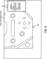
- the display control unit 122A causes the display device 193 to display a screen (see FIG. 9 and the like) including the image of the measurement target 7 received from the image capturing control unit 21.
- the display control unit 122A causes the display device 193 to display a menu 40 for a user to select a kind (such as a circle, a straight line, a dot, and/or a circular arc) of a geometric shape to be measured in addition to the image of the measurement target 7.
- the display control unit 122A appropriately causes the display device 193 to display other necessary information.
- the calculation result output unit 122B outputs a calculation result by the measurement item calculation unit 27 for display on the display device 193.
- the selection receiving unit 23 acquires information about a geometric shape selected on the menu 40 through the input device 195 by a user and position information about a location selected on the image of the measurement target 7 through the input device 195 by the user.
- the geometric shape measurement unit 25 identifies, based on the information acquired by the selection receiving unit 23, a geometric shape in the image of the measurement target 7 (that is, a contour of the measurement target 7 in the image) based on a contrast of the image, and performs a measurement related to the identified geometric shape by an existing measurement method. Specifically, the geometric shape measurement unit 25 performs the following measurement processing. Note that, a geometric shape in an image may not be measured by the following measurement processing method, and may be measured by another existing method.
- the geometric shape measurement unit 25 omits the processing of (3) to (5) in the above-described measurement processing, detects coordinates by the processing of (2), and identifies a geometric shape as a dot.
- the user may not select a kind of a geometric shape to be measured in the menu 40.
- the geometric shape measurement unit 25 performs the above-described processing of (1) to (4), obtains an approximate shape by a least square method from the point sequence on the contour acquired in (4), and obtains a variance from an error between the obtained approximate shape and each point in the point sequence on the contour.
- a kind of the approximate shape that is, a kind of the geometric shape
- the measurement related to the identified geometric shape may be performed based on coordinates of the point sequence on the contour (point sequence data).
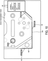
- the geometric shape measurement unit 25 stores a measurement result acquired from the above-described measurement in the measurement result DB 32. Under a condition that the measurement result of the geometric shape is stored in the measurement result DB 32, the display control unit 122A emphasizes and displays the measured geometric shape (contour) on the image of the measurement target 7 as illustrated in FIG. 10 (see signs 142 and 144). The display control unit 122A also displays, as geometric shape-related information selectable by the user, an icon indicating the measured geometric shape such that the icon is selectable by the user through the input device 195 (see signs 42 and 44).
- the measurement result DB 32 is a database for storing a measurement result of a geometric shape and a calculation result of a measurement candidate (that is, a measurement item), and includes a data structure as illustrated in FIGS. 5A and 5B .
- the measurement result DB 32 includes fields such as an ID, a geometric shape or a measurement candidate, items 1, 2, and..., values 1, 2, and..., a child ID, and a parent ID. Identification information provided to the measurement result of the geometric shape or the calculation result of the measurement candidate is stored in the field of the ID.
- a kind (such as a circle, a straight line, a dot, and/or a circle) of the measured geometric shape or a kind (such as an intersection of two straight lines and/or a distance between dots) of the measurement candidate is stored in the field of the geometric shape or the measurement candidate.
- Contents (such as starting point coordinates, ending point coordinates, a length, central coordinates, and/or a diameter) measured for the geometric shape or contents (such as a length, a coordinate value, and/or an angle) calculated for the measurement candidate are stored in the fields of the items 1, 2, and...
- Measurement results or calculation results of the contents stored in the items 1, 2, and... are respectively stored in the fields of the values 1, 2, and....
- the field of the child ID and the parent ID are used to associate the measurement result of the geometric shape with the calculation result of the measurement candidate, and details thereof will be described hereinafter.
- the calculation instruction receiving unit 26 identifies a measurement candidate that holds true based on a combination of the selected geometric shapes.
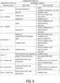
- the calculation instruction receiving unit 26 identifies the measurement candidate corresponding to the combination of the selected geometric shapes based on a combination table 34 ( FIG. 6 ) serving as a definition unit.
- This combination table 34 is information in which a plurality of geometric shapes are associated with measurement candidates that hold true based on a combination of the plurality of geometric shapes.
- the measurement candidates are classified into an item (hereinafter referred to as a display item) displayed on the display device 193 in association with the measurement candidate identified by the combination of the geometric shapes selected by the user and a calculation item (hereinafter referred to as a calculation item) corresponding to each display item.
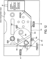
- the calculation instruction receiving unit 26 causes, through the display control unit 122A, the display device 193 to display icons 501, 502, 503, and 504 (see icons indicated by broken lines in FIG. 12 ) of identified measurement candidates (display items) and figures 601, 602, and 603 (see figures indicated by broken lines in FIG. 12 ) indicating the measurement candidates.
- the display control unit 122A causes the icons indicating the measurement candidates to be selectably displayed.
- causing the icons indicating the measurement candidates to be selectably displayed by the display control unit 122A indicates the same meaning as causing the measurement candidates to be displayed.
- selecting the icons indicating the measurement candidates by the user indicates the same meaning as selecting the measurement candidates.
- the information in which a plurality of geometric shapes are associated with measurement candidates that hold true based on a combination of the plurality of geometric shapes is not limited to table data, and may be text data.
- FIG. 6 illustrates a data structure of the combination table 34.
- the combination table 34 includes fields of a combination of geometric shapes selected by a user and a measurement candidate (display item and calculation item).
- a combination of geometric shapes selectable by the user is comprehensively stored in the field of the combination of the geometric shapes.
- the field of the measurement candidate includes two fields of a display item and a calculation item.
- Information about a display item displayed on the display device 193 for a measurement candidate identified based on the combination of the geometric shapes selected by the user is stored in the field of the display item.
- Information about a measurement item (calculation item) calculated for the corresponding display item is stored in the field of the calculation item.
- the display control unit 122A causes the display device 193 to selectably display an icon of "INTERSECTION OF TWO STRAIGHT LINES", an icon of "MEDIAN LINE”, and an icon of "INSCRIBED CIRCLE” as display of measurement candidates (display items).
- the display control unit 122A causes the display device 193 to comprehensively display calculable candidates for measurement, based on the combination of the geometric shapes selected by the user.
- the calculation instruction receiving unit 26 transmits information about the selected measurement candidate to the measurement item calculation unit 27.
- the measurement item calculation unit 27 reads a measurement result of the geometric shape stored in the measurement result DB 32 based on the information about the measurement item selected by the user being received from the calculation instruction receiving unit 26, and calculates the measurement candidate based on the read measurement result.
- the measurement item calculation unit 27 stores the calculation result of the measurement item in the measurement result DB 32. Note that, a method for storing a calculation result of a measurement item in the measurement result DB 32 will be described hereinafter.
- the calculation of a measurement candidate by the measurement item calculation unit 27 is performed by an existing calculation method. For example, under a condition that the calculation instruction receiving unit 26 detects that the user has selected the icon of "INTERSECTION OF TWO STRAIGHT LINES" among the icon of "INTERSECTION OF TWO STRAIGHT LINES", the icon of "MEDIAN LINE", and the icon of "INSCRIBED CIRCLE” displayed on the display device 193, the measurement item calculation unit 27 reads a measurement result of the two straight lines from the measurement result DB 32, and calculates "ANGLE OF INTERSECTION” and "COORDINATE VALUE OF INTERSECTION POINT" being calculation items of "INTERSECTION OF TWO STRAIGHT LINES".
- the measurement item calculation unit 27 reads a unit vector of each of the two straight lines from the measurement result DB 32. Note that, it is assumed that a unit vector of one of the two straight lines is (v1x, v1y, v1z) and a unit vector of the other straight line is (v2x, v2y, v2z).
- the measurement item calculation unit 27 obtains an inner product of the two unit vectors from Expression (1) below, and calculates an angle of intersection by substituting the obtained inner product into Expression (2).
- Inner product v 1 x ⁇ v 2 x ⁇ v 1 y ⁇ v 2 y
- Angle of intersection arccos inner product rad
- the measurement candidates may not be classified into the display item and the calculation item.
- the display item and the calculation item may be unified.
- the display control unit 122A may cause the display device 193 to display, as display of the measurement candidate, an icon of "INTERSECTION OF TWO STRAIGHT LINES (COORDINATE VALUE)" or "INTERSECTION OF TWO STRAIGHT LINES (ANGLE OF INTERSECTION)" obtained by combining the display item and the calculation item.
- the measurement item calculation unit 27 may calculate only an angle of the intersection of the two straight lines.
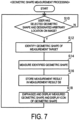
- FIG. 7 is the flowchart showing geometric shape measurement processing. Note that, it is assumed as a premise of the processing in FIG. 7 that processing of capturing an image of the measurement target 7 placed on the XY stage 5 has been completed under control of the image capturing control unit 21. It is also assumed that the display control unit 122A causes the display device 193 to display a screen (a screen including the image of the measurement target 7 and the menu 40) as illustrated in FIG. 9 .
- the selection receiving unit 23 waits until a user selects a geometric shape in the menu 40 through the input device 195 and also designates an arbitrary location on the image in Step S10. Note that, in response to receiving information that the user has selected the geometric shape and designated the arbitrary location on the image, the selection receiving unit 23 transmits the received information to the geometric shape measurement unit 25.
- Step S12 a geometric shape (contour) of the measurement target 7 in the image is identified based on a kind of the selected geometric shape and luminance values (signal intensities) of pixels around the designated location. For example, under a condition that the user selects the geometric shape "STRAIGHT LINE" in the menu 40 and selects a location indicated by a pointer 150 (solid-white arrow) in the screen of FIG. 9 , the geometric shape measurement unit 25 identifies a linear geometric shape (that is, a straight line) in the geometric shape (contour) on the measurement target 7 in the vicinity of the pointer (the vicinity of the location selected by the pointer 150).
- the geometric shape measurement unit 25 measures the identified geometric shape by using the image of the measurement target 7. For example, under a condition that the geometric shape "STRAIGHT LINE" is selected, the geometric shape measurement unit 25 measures starting point coordinates, ending point coordinates, and the like of the linear geometric shape (that is, the straight line) located in the vicinity of the location designated by the user. Note that, under a condition that a geometric shape other than the straight line is selected, a measurement related to the geometric shape is also performed in a similar manner as described above. For example, under a condition that a geometric shape "CIRCLE” is selected, the geometric shape measurement unit 25 measures central coordinates, a diameter, and the like of a geometric shape (contour) closely resembling the circle.
- the geometric shape measurement unit 25 measures central coordinates, a diameter, and the like of a geometric shape (contour) closely resembling the circle.
- the geometric shape measurement unit 25 stores the measurement result in Step S14 in the measurement result DB 32 (see FIG. 5 ).
- Step S18 the display control unit 122A refers to the measurement result DB 32, and causes an icon indicating the geometric shape as geometric shape-related information to be selectably displayed (see the signs 42 and 44 in FIG. 10 ) while causing the measured geometric shape to be emphasized and displayed in the image in the display device 193 (see the signs 142 and 144 in FIG. 10 ). Subsequently, the processing returns to Step S10, and the processing and the determination in Steps S10 to S18 are repeatedly performed.
- the display control unit 122A refers to the measurement result DB 32 and outputs the measurement result of the geometric shape for display. In this way, the user can appropriately view the measurement result of the geometric shape.
- a user has conventionally needed to perform the operations of first selecting a measurement item desired to be calculated from a menu screen in which many measurement items are listed and identifying a combination of geometric shapes needed to calculate the selected measurement item. Selecting a measurement item desired to be calculated from many measurement items has been an extremely complicated operation for the user, and operability for a measurement has been low. Some users have made a mistake in selecting a measurement item, and an inconvenience of failing to perform a desired measurement, for example, has occurred. Even under a condition that a measurement item has been able to be selected, the operation of selecting necessary geometric shapes to calculate the selected measurement item has been needed, which has resulted in poor operability for a measurement.
- the display device 193 displays a plurality of icons of geometric shapes as geometric shape-related information.
- Step S30 in FIG. 8 the calculation instruction receiving unit 26 waits until a user selects any of the icons displayed on the display device 193 through the input device 195.
- icons selectable by the user include an icon of a geometric shape and an icon of a measurement candidate.
- Step S32 the calculation instruction receiving unit 26 determines whether or not the selected icon is an icon of a geometric shape. Under a condition that the determination is denied in Step S32, the processing proceeds to Step S40. Under a condition that the determination is confirmed, the processing proceeds to Step S34.
- Step S34 Under a condition that the processing proceeds to Step S34, that is, under a condition that the user has selected the icon of the geometric shape, the calculation instruction receiving unit 26 emphasizes and displays the selected icon as indicated by signs 42' and 44' in FIG. 11 .
- Step S36 the calculation instruction receiving unit 26 determines whether or not icons of a plurality of geometric shapes are selected. Under a condition that the determination in Step S36 is denied, the processing returns to Step S30, and the processing and the determination in Steps S30 to S36 described above are repeated. Under a condition that the determination in Step S36 is confirmed, the processing proceeds to Step S38.
- the calculation instruction receiving unit 26 refers to the combination table 34 in FIG. 6 , and identifies a measurement candidate (display item) based on geometric shapes (that is, a combination of geometric shapes) respectively corresponding to the icons of the plurality of selected geometric shapes. Then, the calculation instruction receiving unit 26 causes the display device 193 to display the icon of the identified measurement candidate (display item) through the display control unit 122A. The display control unit 122A also causes the display device 193 to display a figure indicating the identified measurement candidate. For example, it is assumed that the user selects two icons of straight lines as geometric shape-related information, as illustrated in FIG. 11 .
- the calculation instruction receiving unit 26 refers to the combination table 34 in FIG. 6 , reads measurement candidates (that is, median line, intersection of two straight lines, and inscribed circle as display items) based on two straight lines ("STRAIGHT LINES ⁇ 2" in FIG. 6 ) as geometric shapes corresponding to the icons of the two selected straight lines, and displays icons 501 to 504 and figures 601 to 603 (see locations in broken lines in FIG. 12 ) of the candidates (display items) as illustrated in FIG. 12 .
- the processing returns to Step S30 after Step S38.
- the calculation instruction receiving unit 26 does not display a measurement candidate on the display device 193 and the processing returns to Step S30. Note that, in the absence of a measurement candidate, the calculation instruction receiving unit 26 may display the absence of the measurement candidate (display a warning) on the display device 193 through the display control unit 122A.
- Step S32 Under a condition that the determination in Step S32 is denied, that is, under a condition that the user has selected the icon of the measurement candidate (display item) in a situation where the icons of the measurement candidates (display items) are displayed as illustrated in FIG. 12 , the calculation instruction receiving unit 26 transmits information about the selected measurement candidate (information about a calculation item corresponding to the display item) to the measurement item calculation unit 27, and the processing proceeds to Step S40. Under a condition that the processing proceeds to Step S40, the measurement item calculation unit 27 reads a measurement result of a geometric shape used to calculate the selected measurement candidate (calculation item) from the measurement result DB 32, and calculates the measurement candidate (calculation item).
- the measurement item calculation unit 27 reads a measurement result of the two selected straight lines from the measurement result DB 32 in FIG. 5A , and calculates measurement items of "INTERSECTION OF TWO STRAIGHT LINES" (coordinate value of intersection point and angle of intersection that are items associated with the display item "INTERSECTION OF TWO STRAIGHT LINES" in FIG. 6 ) based on the read measurement result.
- the measurement item calculation unit 27 stores "INTERSECTION OF TWO STRAIGHT LINES" in the field of the geometric shape, stores “COORDINATE VALUE” in the field of the item 1, and stores calculation values "xN, yN, zN” of coordinates of an intersection point in the field of the value 1.
- CHILD ID the geometric shapes
- Step S44 the display control unit 122A refers to the measurement result DB 32, and displays an icon of the calculated measurement candidate (see a sign 46 in FIG. 13 ) as illustrated in FIG. 13 .
- the calculation result output unit 122B refers to the measurement result DB 32, and outputs the measurement result of the geometric shape and the calculation result of the measurement candidate (measurement item) for display on the display device 193. In this way, the user can appropriately view the measurement result of the geometric shape and the calculation result of the measurement candidate.
- the display control unit 122A causes an icon of a geometric shape in the measurement target 7 to be selectably displayed, and causes a measurement candidate (display item) of the measurement target 7 based on a geometric shape corresponding to the icon of the selected geometric shape to be selectably displayed on the display device 193. Then, the measurement item calculation unit 27 outputs a calculation result of the selected measurement candidate (calculation item) for display on the display device 193.
- the user can input an instruction to calculate the measurement candidate (measurement item) by such an intuitive and simple operation that selects icons of a plurality of geometric shapes on an image of the measurement target 7 displayed on the display device 193 for a portion of the measurement target 7 desired to be measured and selects a specific measurement candidate (measurement item) desired by the user from measurement candidates displayed on the display device 193. Therefore, only candidates for a calculable measurement item for the portion desired to be measured by the user among many measurement items can be selectably displayed. Thus, an instruction to calculate a desired measurement item can be intuitively and simply input without a complicated operation of selecting a specific measurement item from many measurement items.
- an instruction to calculate a measurement candidate (measurement item) can be intuitively input without an operation that requires a lot of time and effort for identifying a combination of geometric shapes necessary to calculate a measurement candidate (measurement item) selected by a user.
- operability of a user in operation for a measurement can be improved. Therefore, a beginner for a measurement, in particular, among users can reliably perform a measurement of a portion desired to be measured in the measurement target 7. Meanwhile, an expert for a measurement can efficiently perform a measurement of a portion desired to be measured.
- the calculation instruction receiving unit 26 refers to the combination table 34 defined by associating a combination of geometric shapes with a measurement candidate, identifies a measurement candidate to be displayed, and displays the measurement candidate through the display control unit 122A.
- the combination table 34 defined by associating a combination of geometric shapes with a measurement candidate, identifies a measurement candidate to be displayed, and displays the measurement candidate through the display control unit 122A.
- the display control unit 122A may not cause the display device 193 to display an icon of the geometric shape (geometric shape-related information) in the geometric shape measurement processing ( FIG. 7 ). For example, an icon of a geometric shape may be displayed before the geometric shape is measured.
- the display control unit 122A may cause the display device 193 to selectably display an icon of the identified geometric shape (geometric shape-related information).
- the geometric shape measurement unit 25 may measure a geometric shape corresponding to the measurement candidate (measurement item) to be calculated in the processing of calculating a measurement candidate ( FIG. 8 ).
- the display control unit 122A displays an icon of a measurement candidate (display item), and under a condition that a user selects an icon of a measurement candidate (display item), the measurement item calculation unit 27 calculates a calculation item corresponding to the selected measurement candidate (display item).
- the measurement item calculation unit 27 may calculate all calculation items corresponding to the displayed measurement candidate (display item) and store all the calculation items in the measurement result DB 32.
- the calculation result output unit 122B may cause a calculation result of the measurement candidate (calculation item) stored in the measurement result DB 32 to be displayed on the display device 193 in response to a request from a user.
- the measurement item calculation unit 27 calculates all calculation items corresponding to a measurement candidate (display item) in the first embodiment, but all measurement candidates (calculation items) may not be calculated. For example, under a condition that a user selects an icon of a measurement candidate (display item), the display control unit 122A may cause the display device 193 to selectably display a list of calculation items corresponding to the measurement candidate (display item). Then, the calculation instruction receiving unit 26 may transmit information about the measurement candidate (calculation item) selected by the user to the measurement item calculation unit 27, and the measurement item calculation unit 27 may calculate the selected calculation item.
- the geometric shape-related information selectable by the user may be, for example, a list of geometric shapes, which have been measured, displayed on the display device 193.
- the user selects an arbitrary geometric shape on the displayed list of the geometric shapes.
- a number may be provided to the geometric shape (emphasized and displayed contour) that has been measured on the image of the measurement target 7, and the same number may be given to the corresponding geometric shape on the list.
- the geometric shape-related information selectable by the user may be an image of a geometric shape in the image of the measurement target 7.
- an image for example, the signs 142 and 144 in FIG. 10
- the geometric shape emphasized and displayed on the image of the measurement target 7 may be selectable.
- the display control unit 122A causes the display device 193 to selectably display an icon indicating a measurement candidate as one example in which a measurement candidate is selectably displayed in the first embodiment, but an icon indicating a measurement candidate may not be used.
- the display control unit 122A may cause the display device 193 to display a list of measurement candidates identified by selection of a geometric shape, and a user may select a measurement candidate (measurement item) to be calculated from the list.
- the display control unit 122A may cause the display device 193 to selectably display the figures 601 to 603 (see FIG. 12 ) indicating the measurement candidates identified by the selection of the geometric shape, and a measurement candidate corresponding to a desired figure selected by the user may be calculated.
- causing the list and the figures indicating the measurement candidates to be selectably displayed in addition to the icons of the measurement candidates by the display control unit 122A indicates the same meaning as selectably displaying the measurement candidates.
- the calculation result output unit 122B may output a calculation result as a file.
- a format of a file may be, for example, a text format, a CSV format, an HTML format, and the like.
- the calculation result output unit 122B may output a calculation result as a paper medium through an external apparatus such as a printer, which is not illustrated.
- a calculation result of the measurement candidate may be output.
- the present variation can be achieved by partially changing the processing in FIGS. 7 and 8 . Hereinafter, details will be described by using FIGS. 7 and 8 .
- Step S10 in the processing in FIG. 7 the selection receiving unit 23 waits until a user selects a geometric shape in the menu 40 through the input device 195 and also designates an arbitrary location on the image. Under a condition that the selection and the designation are performed by the user and the processing proceeds to Step S12, the geometric shape measurement unit 25 calculates coordinates of a point sequence (point sequence data) on a contour of the measurement target 7 and also identifies a geometric shape as described above.
- Step S14 is not performed in the present variation.
- Step S16 the geometric shape measurement unit 25 stores information about the point sequence data acquired in Step S12 in a database.
- the display control unit 122A refers to the database, causes the geometric shape to be emphasized and displayed in the image on the display device 193, and also causes an icon (geometric shape-related information) indicating the geometric shape (such as a circle, a straight line, a dot, and a circular arc) to be selectably displayed.
- the processing returns to Step S10, and the processing and the determination in Steps S10 to S 18 (however, except for Step S14) are repeatedly performed.
- Step S30 the calculation instruction receiving unit 26 waits until a user selects an icon displayed on the display device 193 through the input device 195. Under a condition that an icon indicating a geometric shape is selected and the processing proceeds to Step S32, the calculation instruction receiving unit 26 determines whether or not the selected icon is an icon of a geometric shape. Under a condition that the determination is denied in Step S32, the processing proceeds to Step S40. Under a condition that the determination is confirmed, the processing proceeds to Step S38 (Steps S34 and 36 are not performed in the present variation).
- the calculation instruction receiving unit 26 refers to the measurement item list in FIG. 2 , and identifies a measurement candidate (measurement item in FIG. 2 ) based on a geometric shape corresponding to the icon of the selected geometric shape. Then, the calculation instruction receiving unit 26 causes the display device 193 to display an icon of the identified measurement candidate through the display control unit 122A. For example, under a condition that the user selects an icon of a circle as a geometric shape, icons of central coordinates, a diameter (radius), and circularity are displayed as icons of measurement candidates on the display device 193. Subsequently, the processing returns to Step S30.
- Step S32 determines whether the measurement candidate is a condition that the user has selected the icon of the measurement candidate in a situation where the icon of the measurement candidate is displayed.
- the calculation instruction receiving unit 26 transmits information about the selected measurement candidate to the measurement item calculation unit 27, and the processing proceeds to Step S40.
- the measurement item calculation unit 27 reads information about point sequence data about a geometric shape used to calculate the selected measurement candidate from the database, and calculates the measurement candidate (measurement item).
- the measurement candidate (measurement item) calculated by the measurement item calculation unit 27 is the measurement item exemplified in FIG. 2 .
- the measurement item calculation unit 27 updates the database to a calculation result of the measurement candidate (measurement item).
- the display control unit 122A refers to the database, and causes an icon of the calculated measurement candidate (measurement item) to be displayed.
- the calculation result output unit 122B refers to the database, and outputs the calculation result of the measurement candidate (measurement item) for display on the display device 193.
- a predetermined operation for example, a click of a right mouse button
- the calculation result output unit 122B refers to the database, and outputs the calculation result of the measurement candidate (measurement item) for display on the display device 193.
- the combination table 34 may not include a combination of the selected geometric shapes (for example, the reason is that any physical quantity cannot be calculated from a combination of the selected geometric shapes), and a measurement candidate (display item) may not be displayed in Step S38.
- a second embodiment as follows may be adopted to avoid an occurrence of such a situation and to further improve operability for calculating a measurement candidate (measurement item).
- an image measurement device in the second embodiment has the same configuration as that of the image measurement device 100 in the first embodiment as described above.
- processing along a flowchart in FIG. 14 is performed instead of the processing in FIG. 8 described in the first embodiment.
- the processing in FIG. 14 is different from the processing in FIG. 8 in that processing in Step S35 is performed between the processing in Steps S34 and S36.
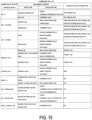
- the calculation instruction receiving unit 26 uses a combination table 134 illustrated in FIG. 15 instead of the combination table 34 in FIG. 6 .
- a geometric shape selectable next shape including a measurement candidate under a condition that selection continues
- a calculable measurement item display item and calculation item
- the user can further select "DOT” and/or "STRAIGHT LINE", and under a condition that the user has already selected two straight lines, the user can further select "STRAIGHT LINE".
- the calculation instruction receiving unit 26 In the processing in FIG. 14 , under a condition that an icon of one or a plurality of geometric shapes (geometric shape-related information) is selected, the calculation instruction receiving unit 26 refers to the combination table 134 in FIG. 15 and identifies a geometric shape selectable next in Step S35. Then, the calculation instruction receiving unit 26 displays, through the display control unit 122A, an icon except for the identified geometric shape (that is, an icon of a geometric shape without a geometric shape selectable next) in a state different from the icon of the identified geometric shape.
- Step S35 the calculation instruction receiving unit 26 refers to the combination table 134, and identifies "STRAIGHT LINE" as a geometric shape that can be combined with the two straight lines corresponding to the icons of the two straight lines. Then, the calculation instruction receiving unit 26 displays, through the display control unit 122A, an icon of a geometric shape (icon of a circle in FIG. 11 ) of geometric shapes that have not yet selected in FIG. 11 except for "STRAIGHT LINE" in a state different from an icon of unselected "STRAIGHT LINE". In this case, for example, a masked icon of the circle may be displayed as illustrated in FIG. 16 . Alternatively, the icon of the circle may be displayed in a color or a concentration different from that of the icon of the unselected straight line.
- Step S36 is performed similarly to the aforementioned first embodiment after Step S35.
- Step S35 may be performed after Step S36 is denied or after the processing in Step S38.
- a geometric shape that cannot be used in the processing of calculating a measurement candidate by being combined with a geometric shape corresponding to an icon of an already selected geometric shape is displayed so as not to be selected by a user.
- a user can be prevented from selecting a geometric shape that does not need to be selected, and can efficiently select a geometric shape. Therefore, operability for calculating a measurement candidate (measurement item) can be further improved.
- an icon of a geometric shape that cannot be selected next may be displayed so as not to be selected in the second embodiment.
- an icon that cancels a selection operation by a user may be displayed.
- a geometric shape that cannot be used in the processing of calculating a measurement candidate by being combined with an already selected geometric shape is displayed in a state different from a geometric shape that can be used in the calculation processing, but this is not limited thereto.
- an icon of a geometric shape that cannot be used in the processing of calculating a measurement candidate by being combined with an already selected geometric shape may be hidden from display.
- a mark, a character, a symbol, and the like may be displayed on at least one of an icon of a geometric shape selectable next and an icon of a geometric shape that cannot be selected next such that a user can distinguish between the icons.
- an icon of "CIRCLE" provided with a cross may be displayed in the example of FIG. 16 .
- a display state or a display appearance of at least one of an icon of a geometric shape selectable next and an icon of a geometric shape that cannot be selected next may be changed with a lapse of time since the icon is displayed. For example, a blinking icon may be displayed.
- a measurement-finished geometric shape that has been finished with measurement is displayed so that a user can not select information about a geometric shape, among the measurement-finished geometric shape, that cannot be used in the processing of calculating a measurement candidate by being combined with an already selected geometric shape, but information about a geometric shape may not be prevented from being selected at a stage before selection.
- the geometric shape measurement processing in FIG. 1 the geometric shape measurement processing in FIG. 1
- Step S12 under a condition that a geometric shape in a location different from a geometric shape that has already been finished with measurement is identified in the presence of the geometric shape that has finished with measurement (Step S12), and a measurement candidate cannot be calculated by combining the identified geometric shape with the geometric shape that has already been finished with measurement, the processing may not proceed to step after the identification of the geometric shape, and a user may be notified that the identified geometric shape cannot be used for calculating a measurement candidate.
- the second embodiment may be appropriately combined with at least one of the above-described first embodiment, embodiments described hereinafter, and the variations.
- a third embodiment described below may be adopted to prevent a user from selecting such a measurement candidate from which an appropriate value cannot be obtained and to further improve operability for calculating a measurement candidate (measurement item).
- an image measurement device in the third embodiment has the same configuration as that of the image measurement device 100 in the first embodiment as described above.
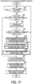
- processing along a flowchart in FIG. 17 is performed instead of the processing in FIG. 8 described in the first embodiment.
- Processing in Steps S37A to S37C instead of Step S38 in FIG. 8 is performed in the processing in FIG. 17 .
- a combination table 234 illustrated in FIG. 18 instead of the combination table 34 in the first embodiment is used in the third embodiment.
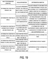
- an inappropriate condition for a candidate is defined for each measurement candidate in the combination table 234 in FIG. 18 .
- Step S37A the calculation instruction receiving unit 26 identifies a measurement candidate corresponding to a combination of geometric shapes corresponding to the icons of the plurality of selected geometric shapes. For example, it is assumed that the user has selected icons of two circles. In this case, the calculation instruction receiving unit 26 refers to the combination table 234 ( FIG. 18 ), and identifies "INTERSECTION OF CIRCLE AND CIRCLE", and/or "TANGENT TO CIRCLE AND CIRCLE".
- Step S37B the calculation instruction receiving unit 26 excludes a measurement candidate that falls under an inappropriate condition for a candidate. For example, under a condition that the user has selected icons of two circles, "DETERMINATION CONDITION OF INTERSECTION OF CIRCLE AND CIRCLE” and “DETERMINATION CONDITION OF TANGENT TO CIRCLE AND CIRCLE" are checked from the combination table 234 ( FIG. 18 ). Under a condition that the icons satisfy the determination conditions, measurement candidates corresponding to the determination conditions are excluded. The excluded measurement candidates are not targets to be displayed as icons.
- the calculation instruction receiving unit 26 determines whether the two circles satisfy conditions illustrated in FIGS. 20A and 20B , for example, and excludes, under a condition that any of the conditions is satisfied, "INTERSECTION OF CIRCLE AND CIRCLE” from measurement candidates.
- FIG. 20A illustrates a case where two circles are located away from each other.
- FIG. 20B illustrates a case where one circle is located in the other circle.
- an absolute value of a difference between radii r1 and r2 of respective circles calculated based on a measurement result of geometric shapes (two circles) is greater than a value of a distance L between centers of the respective circles, the calculation instruction receiving unit 26 determines that there is no intersection point.
- the calculation instruction receiving unit 26 determines whether the two circles satisfy a condition illustrated in FIG. 20C , and excludes, under a condition that the condition is satisfied, "TANGENT TO CIRCLE AND CIRCLE” from measurement candidates. Specifically, as illustrated in FIG.
- the calculation instruction receiving unit 26 determines that there is no tangent.
- Step S37C the calculation instruction receiving unit 26 displays an icon of a measurement candidate (display item) that is identified in Step S37A and is not excluded in Step S37B on the display device 193 through the display control unit 122A. Subsequently, the processing returns to Step S30.
- the user can be prevented from mistakenly selecting an icon of a measurement candidate that does not need to be selected by excluding a measurement candidate (display item) that does not need to be displayed from display targets in advance based on a measurement result of geometric shapes.
- 20D illustrates a case where a circle and a straight line are located away from each other. Under a condition that a distance L between the straight line and the circle calculated based on a measurement result of geometric shapes (straight line and circle) is greater than a radius r of the circle, the calculation instruction receiving unit 26 determines that there is no intersection point.
- a distance L between the straight line and the circle calculated based on a measurement result of geometric shapes is greater than a radius r of the circle
- the calculation instruction receiving unit 26 determines that there is no straight line.
- the calculation instruction receiving unit 26 determines that the two straight lines do not intersect.
- a measurement candidate from which a value cannot be obtained or a measurement candidate having a value deviated from a predetermined range is excluded in advance, and the icon is then displayed.
- a user can be prevented from mistakenly selecting a measurement candidate that cannot be appropriately measured, and can efficiently select a measurement candidate. Therefore, operability for calculating a measurement candidate (measurement item) can be further improved.
- an excluded measurement candidate may be displayed in a state different from a measurement candidate that is not excluded.
- the calculation instruction receiving unit 26 may display a masked icon of an excluded measurement candidate, or display an icon of an excluded measurement candidate in a color or a concentration different from that of an icon of a measurement candidate that is not excluded.
- the calculation instruction receiving unit 26 may also display an icon of an excluded measurement candidate provided with a mark, a character, a symbol, and the like (for example, a cross).
- Step S38 in the processing in FIG. 14 described in the aforementioned second embodiment instead of Steps S37A to S37C described in the third embodiment may be performed.
- the third embodiment may be appropriately combined with at least one of the above-described first and second embodiments, embodiments described hereinafter, and the variations.
- an image measurement device in the fourth embodiment has the same configuration as that of the image measurement device 100 in the first embodiment as described above.
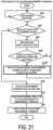
- processing along a flowchart in FIG. 21 is performed instead of the processing in FIG. 8 described in the first embodiment. Note that, it is assumed in the fourth embodiment that the calculation instruction receiving unit 26 counts the number of selected times of a measurement candidate selected in the past for each user in a selection history DB as illustrated in FIG. 22 stored in the HDD 196.
- Step S36 Under a condition that the determination in Step S36 is confirmed in the processing in FIG. 21 , that is, under a condition that a user has selected icons of a plurality of geometric shapes (geometric shape-related information), the processing proceeds to Step S37D. Then, under a condition that the processing proceeds to Step S37D, the calculation instruction receiving unit 26 displays, through the display control unit 122A, an icon of a measurement candidate (display item) corresponding to a combination of the selected geometric shapes. At the time of this display, the calculation instruction receiving unit 26 displays each icon in a different state based on a selection history of a user recorded in the selection history DB.
- the calculation instruction receiving unit 26 refers to the selection history DB in FIG. 22 , and acquires information indicating that the number of selected times of a measurement candidate "INTERSECTION OF TWO STRAIGHT LINES" is 25 times, the number of selected times of "MEDIAN LINE” is three times, and the number of selected times of "INSCRIBED CIRCLE” is zero times. As illustrated in FIG. 23 , the calculation instruction receiving unit 26 then displays an icon of each of the measurement candidates in the size according to the number of time it has been acquired.
- the icon of "INTERSECTION OF TWO STRAIGHT LINES" having the greatest number of selected times is displayed to be the largest, and the icon of "INSCRIBED CIRCLE” having the smallest number of selected times is displayed to be the smallest.
- the icon of "MEDIAN LINE” is displayed to be smaller than the icon of "INTERSECTION OF TWO STRAIGHT LINES" and larger than the icon of "INSCRIBED CIRCLE". In this way, the user can easily find and select an icon frequently selected by the user.
- Step S30 The processing returns to Step S30 after Step S37D.
- the processing other than Step S37D is the same as that in the first embodiment ( FIG. 8 ).
- an icon of a measurement candidate is displayed in each different state based on a selection history of the measurement candidate.
- the user can easily find and select an icon of a measurement candidate frequently selected by the user. In this way, operability for calculating a measurement candidate (measurement item) can be improved.
- icons vary in size according to a selection history
- an icon of a measurement candidate having a great number of selected times may be displayed in a different color and concentration so as to stand out.
- numbers or marks indicating decreasing order of the number of selected times or the number of selected times may be displayed on icons.
- the selection history DB may be created by collecting a selection history for each kind or lot of a measurement target. In this way, display with consideration to a tendency for calculation of a measurement candidate of a measurement target can also be achieved. Thus, usability for a user can be improved. Further, the selection history DB may be created by collecting a selection history for each user and each kind or lot of a measurement target.
- the selection history DB is created for a measurement candidate and an icon of the measurement candidate is displayed in each different state based on the selection history in the fourth embodiment, but the selection history DB may be created for, for example, a geometric shape other than a measurement candidate.
- the calculation instruction receiving unit 26 may display an icon of a geometric shape in each different state based on the selection history DB through the display control unit 122A. Specifically, icons of geometric shapes varying in size, color, and concentration according to the number of selected times in the past may be displayed, or numbers and marks indicating the number of selected times may be displayed on icons.
- the fourth embodiment may be appropriately combined with at least one of the above-described first to third embodiments, embodiments described hereinafter, and the variations.
- FIG. 24A illustrates a display example of icons of geometric shapes and icons of measurement candidates according to the fifth embodiment.
- the calculation instruction receiving unit 26 displays, through the display control unit 122A, measurement candidates corresponding to all combinations included in a plurality of geometric shapes selected by a user. That is, under a condition that the user selects an icon of one circle and icons of two straight lines, it is assumed that respective measurement candidates corresponding to a combination of the icon of the circle and the icon of one of the straight lines, a combination of the icon of the circle and the icon of the other straight line, and a combination of the icons of the two straight lines are displayed.
- FIG. 24A illustrates a display example in which a user selects one circle and two straight lines.
- drawing of a measurement candidate "INSCRIBED CIRCLE” corresponding to the two straight lines is omitted to avoid complication of the diagram.
- the display control unit 122A groups and displays icons to display the icons. Specifically, as illustrated in FIG. 24A , the calculation instruction receiving unit 26 displays frames indicated by dot-and-dash lines around the icons of the two straight lines and the respective icons of "MEDIAN LINE", “MEDIAN LINE”, and "INTERSECTION OF TWO STRAIGHT LINES” corresponding to the two straight lines, displays frames indicated by thick solid lines around the icons of the circle and one of the straight lines and the icon of "DISTANCE (BETWEEN DOT AND STRAIGHT LINE)" as a measurement candidate (display item) corresponding to the circle and one of the straight lines, and displays frames indicated by thick broken lines around the icons of the circle and the other straight line and the icon of "DISTANCE (BETWEEN DOT AND STRAIGHT LINE)" as a measurement candidate (display item) corresponding to the circle and the other straight line, through the display control unit 122A.
- the calculation instruction receiving unit 26 displays frames indicated by dot-and-dash lines around the icons
- icons are expressed such that groups can be identified by types of frame lines is described, but this is not limited thereto.
- Icons may be expressed such that groups can be identified by color of frame lines, color in frames, and the like, or expressed such that groups can be identified by providing a specific number, character, mark, and the like to each of the icons.
- the display control unit 122A can group measurement candidates of the same kind and display the measurement candidates to be close to each other. In this way, the user can easily recognize a kind of a displayed measurement candidate and thus easily select a measurement candidate. As a result, operability for calculating a measurement candidate can be improved.
- measurement candidates of the same kind may not be grouped together and displayed to be close to each other. Icons may be expressed such that a group of measurement candidates of the same kind can be identified by color of frame lines, color in frames, and the like, or expressed such that a group of measurement candidates of the same kind can be identified by providing a specific number, character, mark, and the like to each of the icons. Note that, under a condition that measurement candidates of the same kind are grouped, the fifth embodiment is also applicable to a case where a plurality of measurement candidates corresponding to one combination of a plurality of geometric shapes selected by a user are displayed.
- the fifth embodiment may be appropriately combined with at least one of the above-described first to fourth embodiments, embodiments described hereinafter, and the variations.
- FIGS. 25 to 27 Next, a sixth embodiment will be described based on FIGS. 25 to 27 .
- FIG. 25 illustrates a display example of icons according to the sixth embodiment.
- a measurement candidate corresponding to a combination of geometric shapes for example, two straight lines
- a user selects one measurement candidate (for example, median line)
- the selected measurement candidate is calculated (similarly to the first to fifth embodiments).
- the user further selects the already calculated measurement candidate (for example, median line) and a geometric shape (for example, circle)
- a measurement candidate according to the selection is further displayed.
- the selected measurement candidate for example, distance
- the calculation instruction receiving unit 26 refers to a combination table 334 as illustrated in FIG. 26 .
- the combination table 334 in FIG. 26 further includes a field of a substitutable shape in addition to the fields of the combination table 34 in FIG. 6 .
- Information indicating which geometric shape can substitute for an already calculated measurement candidate is stored in the field of the substitutable shape. For example, information indicating that measurement candidates "SPLIT DOT", and/or "AVERAGE DOT" can be substituted as a geometric shape "DOT" is stored in the combination table 334.
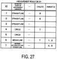
- FIG. 25 illustrates the display example in which the median line (sign 43) is calculated based on the two straight lines (signs 42 and 44) as mentioned above, and a distance between the calculated median line and the circle (sign 45) is then calculated.
- the measurement item calculation unit 27 stores data as illustrated in FIG. 27 in the measurement result DB 32.
- the sixth embodiment may be appropriately combined with at least one of the above-described first to fifth embodiments, an embodiment described hereinafter, and the variations.
- FIGS. 28 and 29 Next, a seventh embodiment will be described based on FIGS. 28 and 29 .
- an image of a measurement target can be zoomed in or out, and a user selects and measures many geometric shapes (for example, circles) in the image with the image being zoomed in. Then, the image is zoomed out and displayed as illustrated in FIG. 28A to obtain a distance between two circles located away from each other.
- geometric shapes for example, circles
- FIG. 28A there are many icons of circles being measured geometric shapes, and thus it is difficult for the user to select an icon of a geometric shape used to calculate a measurement candidate.
- the display control unit 122A identifies ranges (starting point coordinates, horizontal width of window, and vertical width of window) of the windows W1 and W2. Note that, it is assumed that starting point coordinates are, for example, coordinates of an upper left corner of the window.
- the user designates a position and a size of the window by identifying two points located diagonally of the window. Specifically, the user designates a position and a size of the window by a drag operation with the input device 195 being a mouse or a pinch-out operation with the input device 195 being a touch panel.
- the display control unit 122A identifies a geometric shape included in the range of each of the identified windows W1 and W2, and causes the display device 193 to display only an icon of the identified geometric shape.
- an icon of a geometric shape included in a window and an icon of a geometric shape that is not included in the window may be displayed in different states such that the icon of the geometric shape included in the range of the window is more easily selected than the other icon.
- an icon of a geometric shape included in a window and an icon of a geometric shape that is not included in the window may vary in size, shape, color, concentration, and the like of the icons to be displayed.
- the seventh embodiment under a condition that a list of measurement results stored in the measurement result DB 32 is displayed, only a measurement result of a geometric shape included in a range of a window designated by a user and only a calculation result of a measurement candidate may be displayed. In this way, a list of only measurement results in a range needed for the user can be displayed.
- the seventh embodiment may be appropriately combined with at least one of the above-described first to sixth embodiments and the variations.
- a product such as a component of an automobile and a mechanical component manufactured at a factory and the like is measured by using the image measurement device according to the aforementioned first to seventh embodiments, and quality of the product is determined based on a measurement result. Further, the product is selected as a non-defective product or a defective product based on a determination result, and only the product selected as a non-defective product proceeds to the next step.
- the aforementioned processing functionality can be achieved by a computer.
- a program including a processing content of the functionality needed for the processing device is provided.
- the aforementioned processing functionality is achieved on the computer by the program executed by the computer.
- the program including the processing content may be recorded in a computer-readable recording medium (however, except for carrier wave).
- a portable recording medium such as a digital versatile disc (DVD) and a compact disk read only memory (CD-ROM) in which the program is recorded is sold to distribute the program.
- the program may be stored in a storage device of a server computer and transferred from the server computer to the other computer through a network.
- the computer executing the program stores, for example, the program recorded in the portable recording medium or the program transferred from the server computer in the storage device of the computer. Then, the computer reads the program from the storage device, and executes processing following the program. Note that, the computer may read the program directly from the portable recording medium and execute the processing following the program. The computer may also execute the processing following the received program successively every time the program is transferred from the server computer.
Landscapes
- Engineering & Computer Science (AREA)
- Physics & Mathematics (AREA)
- General Physics & Mathematics (AREA)
- Computer Vision & Pattern Recognition (AREA)
- Theoretical Computer Science (AREA)
- Geometry (AREA)
- Quality & Reliability (AREA)
- Length Measuring Devices By Optical Means (AREA)
- Image Analysis (AREA)
Claims (31)
- Procédé de mesure d'image pour une cible de mesure comprenant :l'affichage d'une pluralité d'informations relatives à une forme géométrique, chacune étant une information relative à une forme géométrique identifiée dans une image de la cible de mesure ;la réception d'une sélection de plus d'une de la pluralité d'informations relatives à une forme géométrique ;l'affichage d'une information relative à un candidat de mesure d'un candidat de mesure, le candidat de mesure représentant un article de mesure associé à une combinaison des formes géométriques correspondant aux informations relatives à une forme géométrique sélectionnée ;la réception d'une sélection de l'information relative à un candidat de mesure affichée ; etl'émission d'un résultat de calcul du candidat de mesure correspondant à l'information relative à un candidat de mesure sélectionnée du candidat de mesure.
- Procédé de mesure d'image selon la revendication 1, dans lequel
l'affichage de l'information relative à un candidat de mesure du candidat de mesure inclut la référence à des informations dans lesquelles une combinaison d'une pluralité de formes géométriques est associée à un candidat de mesure de la cible de mesure sur la base de la forme géométrique, et l'affichage de l'information relative à un candidat de mesure d'un candidat de mesure de la cible de mesure sur la base d'une combinaison d'une pluralité de formes géométriques correspondant aux informations relatives à une forme géométrique sélectionnées. - Procédé de mesure d'image selon la revendication 1 ou la revendication 2, dans lequell'affichage des informations relatives à une forme géométrique inclut l'affichage d'une pluralité d'éléments d'informations relatives à une forme géométrique, etl'affichage de l'information relative à un candidat de mesure du candidat de mesure inclut l'affichage d'une information relative d'un candidat de mesure de la cible de mesure sur la base d'une combinaison de formes géométriques correspondant à la pluralité d'éléments d'informations relatives à une forme géométrique qui est sélectionnée parmi la pluralité d'éléments des informations relatives à une forme géométrique.
- Procédé de mesure d'image selon la revendication 3, dans lequel
l'affichage des informations relatives à une forme géométrique inclut l'affichage d'une information relative à une forme géométrique non sélectionnée correspondant à une forme géométrique pour laquelle un candidat de mesure est établi en combinaison avec une forme géométrique correspondant à une information relative à une forme géométrique déjà sélectionnée correspondant à une autre forme géométrique dans un état différent d'une autre information relative à une forme géométrique, ou le non-affichage de l'autre information relative à une forme géométrique correspondant à une autre forme géométrique. - Procédé de mesure d'image selon la revendication 3, dans lequel
l'affichage des informations relatives à une forme géométrique inclut l'affichage d'une information relative à une forme géométrique correspondant à une forme géométrique incluse dans une plage désignée et d'une information relative à une forme géométrique correspondant à une forme géométrique qui n'est pas incluse dans la plage désignée dans un état différent, ou le non-affichage de l'information relative à une forme géométrique correspondant à une forme géométrique qui n'est pas incluse dans la plage désignée. - Procédé de mesure d'image selon l'une quelconque des revendications 1 à 5, dans lequel
l'affichage de l'information relative à un candidat de mesure du candidat de mesure comporte l'affichage d'une information relative d'un candidat de mesure dans lequel une valeur ne peut pas être calculée ou une valeur calculée s'écarte d'une valeur seuil prédéterminée parmi l'information relative à un candidat de mesure du candidat de mesure dans un état différent de l'information relative à un candidat de mesure d'un autre candidat de mesure, ou le non-affichage de l'information relative du candidat de mesure dans lequel la valeur ne peut pas être calculée ou la valeur calculée s'écarte de la valeur seuil prédéterminée parmi l'information relative à un candidat de mesure du candidat de mesure. - Procédé de mesure d'image selon l'une quelconque des revendications 1 à 6, dans lequel
l'affichage de l'information relative à un candidat de mesure du candidat de mesure inclut l'affichage de l'information relative à un candidat de mesure du candidat de mesure dans chaque état différent sur la base d'un historique de sélection de l'information relative à un candidat de mesure du candidat de mesure. - Procédé de mesure d'image selon l'une quelconque des revendications 1 à 7, dans lequel
l'affichage de l'information relative à un candidat de mesure du candidat de mesure inclut le regroupement et l'affichage d'une pluralité d'éléments d'informations relatives à un candidat de mesure de candidats de mesure associés. - Procédé de mesure d'image selon l'une quelconque des revendications 1 à 8, dans lequel
l'affichage de l'information relative à un candidat de mesure du candidat de mesure inclut l'affichage d'une correspondance entre les informations relatives à une forme géométrique et l'information relative à un candidat de mesure du candidat de mesure sur la base de la pluralité de formes géométriques correspondant aux informations relatives à une forme géométrique. - Procédé de mesure d'image selon l'une quelconque des revendications 1 à 9, comprenant en outre :
l'identification d'une forme géométrique à partir d'une image de la cible de mesure. - Procédé de fabrication d'un objet comprenant les étapes consistant à :fabriquer un objet ;calculer le candidat de mesure de l'objet fabriqué lors de l'étape de fabrication servant de cible de mesure en utilisant le procédé de mesure d'image selon l'une quelconque des revendications 1 à 10 ; etdéterminer la qualité de l'objet sur la base d'un résultat de calcul lors de l'étape de calcul.
- Programme de mesure d'image pour une mesure d'une image d'une cible de mesure amenant un ordinateur à mettre en oeuvre le traitement suivant :l'affichage d'une pluralité d'informations relatives à une forme géométrique, chacune étant une information relative à une forme géométrique identifiée dans une image d'une cible de mesure ;la réception d'une sélection de plus d'une de la pluralité d'informations relatives à une forme géométrique ;l'affichage d'une information relative à un candidat de mesure d'un candidat de mesure, le candidat de mesure représentant un article de mesure associé à une combinaison des formes géométriques correspondant aux informations relatives à une forme géométrique sélectionnées ;la réception d'une sélection de l'information relative à un candidat de mesure ; etl'émission d'un résultat de calcul du candidat de mesure correspondant à l'information relative à un candidat de mesure sélectionnée du candidat de mesure.
- Programme de mesure d'image selon la revendication 12, dans lequell'affichage des informations relatives à une forme géométrique inclut l'affichage d'une pluralité d'éléments d'informations relatives à une forme géométrique dans la cible de mesure, etl'affichage de l'information relative à un candidat de mesure du candidat de mesure inclut l'affichage d'une information relative à un candidat de mesure d'un candidat de mesure de la cible de mesure sur la base d'une combinaison de formes géométriques correspondant à une pluralité d'éléments d'informations relatives à une forme géométrique qui est sélectionnée parmi la pluralité affichée d'éléments des informations relatives à une forme géométrique.
- Programme de mesure d'image selon la revendication 13, dans lequel
l'affichage des informations relatives à une forme géométrique inclut l'affichage d'une information relative à une forme géométrique non sélectionnée correspondant à une forme géométrique pour laquelle le candidat de mesure est établi en combinaison avec une forme géométrique correspondant à une information relative à une forme géométrique déjà sélectionnée dans un état différent d'une autre information relative à une forme géométrique correspondant à une autre forme géométrique, ou le non-affichage de l'autre information relative à une forme géométrique correspondant à l'autre forme géométrique. - Programme de mesure d'image selon la revendication 13, dans lequel
l'affichage des informations relatives à une forme géométrique inclut l'affichage d'une information relative à une forme géométrique correspondant à une forme géométrique incluse dans une plage désignée et d'une information relative à une forme géométrique correspondant à une forme géométrique qui n'est pas incluse dans la plage désignée dans un état différent, ou le non-affichage de l'information relative à une forme géométrique correspondant à une forme géométrique qui n'est pas incluse dans la plage désignée. - Programme de mesure d'image selon l'une quelconque des revendications 12 à 15, dans lequel
l'affichage de l'information relative à un candidat de mesure du candidat de mesure inclut l'affichage d'une information relative à un candidat de mesure d'un candidat de mesure dans lequel une valeur ne peut pas être calculée ou une valeur calculée s'écarte d'une valeur seuil prédéterminée parmi l'information relative à un candidat de mesure du candidat de mesure dans un état différent de l'information relative à un candidat de mesure d'un autre candidat de mesure, ou le non-affichage du candidat de mesure dans lequel la valeur ne peut pas être calculée ou la valeur calculée s'écarte de la valeur seuil prédéterminée parmi l'information relative à un candidat de mesure du candidat de mesure. - Programme de mesure d'image selon l'une quelconque des revendications 12 à 16, dans lequel
l'affichage de l'information relative à un candidat de mesure du candidat de mesure inclut l'affichage de l'information relative à un candidat de mesure du candidat de mesure dans chaque état différent sur la base d'un historique de sélection de l'information relative à un candidat de mesure du candidat de mesure. - Programme de mesure d'image selon l'une quelconque des revendications 12 à 17, dans lequel
l'affichage de l'information relative à un candidat de mesure du candidat de mesure inclut le regroupement et l'affichage d'une pluralité d'éléments d'informations relatives à un candidat de mesure de candidats de mesure associés. - Programme de mesure d'image selon l'une quelconque des revendications 12 à 18, dans lequel
l'affichage de l'information relative à un candidat de mesure du candidat de mesure inclut l'affichage d'une correspondance entre les informations relatives à une forme géométrique et l'information relative à un candidat de mesure du candidat de mesure sur la base de la pluralité de formes géométriques correspondant aux informations relatives à une forme géométrique. - Programme de mesure d'image selon l'une quelconque des revendications 12 à 19, dans lequel l'information relative à une forme géométrique inclut au moins l'une parmi une icône indiquant une forme géométrique, une liste indiquant une forme géométrique et une image indiquant une forme géométrique.
- Programme de mesure d'image selon l'une quelconque des revendications 12 à 20, dans lequel
dans lequel l'information relative à un candidat de mesure du candidat de mesure inclut au moins l'une parmi une icône indiquant un candidat de mesure, une liste indiquant un candidat de mesure et une image indiquant un candidat de mesure. - Dispositif (100) de mesure d'image configuré pour mesurer une image d'une cible (7) de mesure comprenant :une unité (122A) de commande d'affichage configurée pour amener un dispositif (193) d'affichage à afficher une pluralité d'informations relatives à une forme géométrique, chacune étant une information relative à une forme géométrique identifiée dans une image d'une cible de mesure, l'unité de commande d'affichage étant configurée pour amener le dispositif d'affichage à afficher, en réponse à la réception d'une sélection de plus d'une de la pluralité d'informations relatives à une forme géométrique dans la cible de mesure, une information relative à un candidat de mesure d'un candidat de mesure, le candidat de mesure représentant un article de mesure associé à une combinaison des formes géométriques correspondant aux informations relatives à une forme géométrique sélectionnées ; etune unité (122B) de sortie configurée pour délivrer en sortie, en réponse à la réception d'une sélection d'une information relative à un candidat de mesure affichée, un résultat de calcul du candidat de mesure correspondant à l'information relative à un candidat de mesure sélectionnée du candidat de mesure.
- Dispositif de mesure d'image selon la revendication 22, dans lequel
l'unité de commande d'affichage amène le dispositif d'affichage à afficher, en réponse à la réception de sélections d'une pluralité d'éléments d'informations relatives à une forme géométrique dans la cible de mesure, l'information relative à un candidat de mesure d'un candidat de mesure de la cible de mesure sur la base d'une combinaison de formes géométriques correspondant à la pluralité d'éléments d'informations relatives à une forme géométrique. - Dispositif de mesure d'image selon la revendication 22, dans lequel
l'unité de commande d'affichage amène le dispositif d'affichage à afficher une information relative à une forme géométrique non sélectionnée correspondant à une forme géométrique pour laquelle le candidat de mesure est établi en combinaison avec une forme géométrique correspondant à une information relative à une forme géométrique déjà sélectionnée dans un état différent d'une autre information relative à une forme géométrique correspondant à une autre forme géométrique, ou à ne pas afficher l'autre information relative à une forme géométrique correspondant à l'autre forme géométrique. - Dispositif de mesure d'image selon la revendication 22, dans lequel
l'unité de commande d'affichage amène le dispositif d'affichage à afficher une information relative à une forme géométrique correspondant à une forme géométrique incluse dans une plage désignée et une information relative à une forme géométrique correspondant à une forme géométrique qui n'est pas incluse dans la plage désignée dans un état différent, ou à ne pas afficher l'information relative à une forme géométrique correspondant à une forme géométrique qui n'est pas incluse dans la plage désignée. - Dispositif de mesure d'image selon l'une quelconque des revendications 22 à 25, dans lequel
l'unité de commande d'affichage amène le dispositif d'affichage à afficher une information relative à un candidat de mesure d'un candidat de mesure dans lequel une valeur ne peut pas être calculée ou une valeur calculée s'écarte d'une valeur seuil prédéterminée parmi l'information relative à un candidat de mesure du candidat de mesure dans un état différent de l'information relative à un candidat de mesure d'un autre candidat de mesure, ou à ne pas afficher le candidat de mesure dans lequel la valeur ne peut pas être calculée ou la valeur calculée s'écarte de la valeur seuil prédéterminée parmi l'information relative à un candidat de mesure du candidat de mesure. - Dispositif de mesure d'image selon l'une quelconque des revendications 22 à 26, dans lequel
l'unité de commande d'affichage amène le dispositif d'affichage à afficher l'information relative à un candidat de mesure du candidat de mesure dans chaque état différent sur la base d'un historique de sélection de l'information relative à un candidat de mesure du candidat de mesure. - Dispositif de mesure d'image selon l'une quelconque des revendications 22 à 27, dans lequel
l'unité de commande d'affichage amène le dispositif d'affichage à regrouper et afficher une pluralité d'éléments d'informations relatives à un candidat de mesure de candidats de mesure associés. - Dispositif de mesure d'image selon l'une quelconque des revendications 22 à 28, dans lequel
l'unité de commande d'affichage amène le dispositif d'affichage à afficher une correspondance entre les informations relatives à une forme géométrique et l'information relative à un candidat de mesure du candidat de mesure sur la base de la pluralité de formes géométriques correspondant aux informations relatives à une forme géométrique. - Dispositif de mesure d'image selon l'une quelconque des revendications 22 à 29, dans lequel l'information relative à une forme géométrique inclut au moins l'une parmi une icône indiquant une forme géométrique, une liste indiquant une forme géométrique et une image indiquant une forme géométrique.
- Dispositif de mesure d'image selon l'une quelconque des revendications 23 à 30, dans lequel l'information relative à un candidat de mesure du candidat de mesure inclut au moins l'une parmi une icône indiquant un candidat de mesure, une liste indiquant un candidat de mesure et une image indiquant un candidat de mesure.
Applications Claiming Priority (1)
| Application Number | Priority Date | Filing Date | Title |
|---|---|---|---|
| PCT/JP2016/062860 WO2017183211A1 (fr) | 2016-04-22 | 2016-04-22 | Procédé de mesure d'image, programme de mesure d'image, dispositif de mesure d'image et procédé de fabrication d'objet |
Publications (3)
| Publication Number | Publication Date |
|---|---|
| EP3460754A1 EP3460754A1 (fr) | 2019-03-27 |
| EP3460754A4 EP3460754A4 (fr) | 2020-02-26 |
| EP3460754B1 true EP3460754B1 (fr) | 2023-11-29 |
Family
ID=60115859
Family Applications (1)
| Application Number | Title | Priority Date | Filing Date |
|---|---|---|---|
| EP16899483.8A Active EP3460754B1 (fr) | 2016-04-22 | 2016-04-22 | Procédé de mesure d'image, programme de mesure d'image, dispositif de mesure d'image et procédé de fabrication d'objet |
Country Status (4)
| Country | Link |
|---|---|
| US (1) | US11195294B2 (fr) |
| EP (1) | EP3460754B1 (fr) |
| JP (1) | JP6699722B2 (fr) |
| WO (1) | WO2017183211A1 (fr) |
Families Citing this family (5)
| Publication number | Priority date | Publication date | Assignee | Title |
|---|---|---|---|---|
| JP6985158B2 (ja) * | 2018-01-12 | 2021-12-22 | 株式会社ミツトヨ | 画像測定機およびプログラム |
| JP7489671B2 (ja) * | 2019-10-17 | 2024-05-24 | パナソニックIpマネジメント株式会社 | 補正パラメータ算出方法、変位量算出方法、補正パラメータ算出装置、及び、変位量算出装置 |
| WO2024227950A1 (fr) * | 2023-05-04 | 2024-11-07 | Leica Instruments (Singapore) Pte. Ltd. | Appareil pour un système d'imagerie optique, système d'imagerie optique, procédé et programme informatique |
| WO2024227952A1 (fr) * | 2023-05-04 | 2024-11-07 | Leica Instruments (Singapore) Pte. Ltd. | Appareil pour un système d'imagerie optique, système d'imagerie optique, procédé et programme informatique |
| CN117830925B (zh) * | 2023-11-29 | 2025-05-16 | 长江三峡通航管理局 | 一种基于图像处理的船舶禁停监测方法及系统 |
Family Cites Families (25)
| Publication number | Priority date | Publication date | Assignee | Title |
|---|---|---|---|---|
| US5657251A (en) * | 1995-10-02 | 1997-08-12 | Rockwell International Corporation | System and process for performing optimal target tracking |
| US5988862A (en) * | 1996-04-24 | 1999-11-23 | Cyra Technologies, Inc. | Integrated system for quickly and accurately imaging and modeling three dimensional objects |
| JP3924855B2 (ja) * | 1997-08-19 | 2007-06-06 | 株式会社ニコン | 画像測定機及びその方法 |
| JP3847946B2 (ja) * | 1998-03-06 | 2006-11-22 | 株式会社ミツトヨ | 画像測定機の測定結果ファイル作成方法 |
| JP3810694B2 (ja) * | 2002-02-15 | 2006-08-16 | 三菱電機株式会社 | パターン検査装置及びパターン検査方法 |
| US7451059B2 (en) * | 2003-03-02 | 2008-11-11 | Tomer Malchi | True azimuth and north finding method and system |
| JP4044958B2 (ja) * | 2003-07-10 | 2008-02-06 | 株式会社森精機製作所 | 自動プログラミング装置 |
| US8009871B2 (en) * | 2005-02-08 | 2011-08-30 | Microsoft Corporation | Method and system to segment depth images and to detect shapes in three-dimensionally acquired data |
| JP5095644B2 (ja) * | 2009-01-23 | 2012-12-12 | 株式会社キーエンス | 画像計測装置及びコンピュータプログラム |
| CA2683206C (fr) * | 2009-10-17 | 2018-07-03 | Hermary Opto Electronics Inc. | Methode et appareillage d'imagerie ameliorees |
| FI122500B (fi) * | 2009-11-11 | 2012-02-29 | Andritz Oy | Menetelmä ja laitteisto pyörivän sylinterimäisen laitteen mittaamiseksi ja linjaamiseksi |
| JP2011175477A (ja) * | 2010-02-24 | 2011-09-08 | Canon Inc | 3次元計測装置、処理方法及びプログラム |
| US9031805B2 (en) * | 2011-03-22 | 2015-05-12 | Yamaha Corporation | Geomagnetic field measurement device, offset determination method, and computer readable recording medium therefor |
| US8863398B2 (en) * | 2011-04-01 | 2014-10-21 | Lockheed Martin Corporation | Feature-based coordinate reference |
| JP2013036964A (ja) * | 2011-08-11 | 2013-02-21 | Mitsutoyo Corp | 画像測定装置及び画像測定方法 |
| EP2801787B1 (fr) * | 2011-12-27 | 2019-04-24 | Sumco Corporation | Procédé permettant de mesurer la forme tridimensionnelle d'un creuset en verre de silice, et procédé de production de silicium monocristallin |
| JP6052956B2 (ja) * | 2012-07-02 | 2016-12-27 | 株式会社ミツトヨ | 形状解析方法および形状解析プログラム |
| WO2015052941A1 (fr) * | 2013-10-11 | 2015-04-16 | 古河電気工業株式会社 | Procédé d'inspection d'épaisseur de revêtement et dispositif d'inspection d'épaisseur de revêtement |
| JP6271953B2 (ja) * | 2013-11-05 | 2018-01-31 | キヤノン株式会社 | 画像処理装置、画像処理方法 |
| JP6314464B2 (ja) * | 2013-12-12 | 2018-04-25 | オムロン株式会社 | 画像処理装置、画像処理方法および画像処理プログラム |
| JP6465682B2 (ja) * | 2014-03-20 | 2019-02-06 | キヤノン株式会社 | 情報処理装置、情報処理方法及びプログラム |
| WO2015183550A1 (fr) * | 2014-05-27 | 2015-12-03 | Bourbaki 13, Inc. | Détermination d'informations en trois dimensions à partir de projections ou de placement de motifs à deux dimensions |
| JP6418884B2 (ja) * | 2014-10-10 | 2018-11-07 | キヤノン株式会社 | 三次元計測装置、三次元計測方法及びプログラム |
| US20180374239A1 (en) * | 2015-11-09 | 2018-12-27 | Cognex Corporation | System and method for field calibration of a vision system imaging two opposite sides of a calibration object |
| US11439508B2 (en) * | 2016-11-30 | 2022-09-13 | Fited, Inc. | 3D modeling systems and methods |
-
2016
- 2016-04-22 WO PCT/JP2016/062860 patent/WO2017183211A1/fr not_active Ceased
- 2016-04-22 US US16/095,215 patent/US11195294B2/en active Active
- 2016-04-22 JP JP2018512766A patent/JP6699722B2/ja active Active
- 2016-04-22 EP EP16899483.8A patent/EP3460754B1/fr active Active
Also Published As
| Publication number | Publication date |
|---|---|
| JPWO2017183211A1 (ja) | 2019-01-31 |
| US20190139247A1 (en) | 2019-05-09 |
| EP3460754A4 (fr) | 2020-02-26 |
| EP3460754A1 (fr) | 2019-03-27 |
| JP6699722B2 (ja) | 2020-05-27 |
| WO2017183211A1 (fr) | 2017-10-26 |
| US11195294B2 (en) | 2021-12-07 |
Similar Documents
| Publication | Publication Date | Title |
|---|---|---|
| US7394926B2 (en) | Magnified machine vision user interface | |
| EP3460754A1 (fr) | Procédé de mesure d'image, programme de mesure d'image, dispositif de mesure d'image et procédé de fabrication d'objet | |
| US7627162B2 (en) | Enhanced video metrology tool | |
| JP5956814B2 (ja) | 外観検査装置、外観検査方法及びコンピュータプログラム | |
| US7522763B2 (en) | Method of measuring occluded features for high precision machine vision metrology | |
| CN109542276B (zh) | 一种触控点识别方法及装置和显示设备 | |
| JP6243705B2 (ja) | 自動パラメータ設定選択肢を含むエッジ測定ビデオツール及びインタフェース | |
| JP2011526706A (ja) | 使用者のジェスチャの検出結果に依存した、加工物の一回の測定の複数の結果の表示 | |
| EP2387000B1 (fr) | Appareil de mesure d'images, programme et procédé d'enseignement d'appareil de mesure d'images | |
| WO2016147653A1 (fr) | Dispositif et procédé de détection d'objet et support d'enregistrement | |
| JP2012225913A (ja) | マシンビジョンシステムにおける潜在的な干渉要素の検査 | |
| JP2014215301A (ja) | エッジ検出方法 | |
| WO2003102500A1 (fr) | Procede d'obtention de coordonnees 3 d | |
| US10217011B2 (en) | Apparatus and method for facilitating manual sorting of slides | |
| JP7010327B2 (ja) | 表示方法、画像測定方法、プログラム及び測定装置、並びに物品の製造方法 | |
| US12400351B2 (en) | Workpiece image analyzing device, workpiece image analyzing method, and program | |
| CN110044296B (zh) | 3d形状的自动跟踪方法和测量机 | |
| JP2014093785A (ja) | エッジ測定ビデオツールパラメータ設定ユーザインタフェース | |
| JP5104291B2 (ja) | 画像解析プログラム、画像解析装置、および画像解析方法 | |
| JP5170429B2 (ja) | 分析装置用画像表示装置及び該装置を用いた表面分析装置 | |
| JP3645643B2 (ja) | エッジ検出方式 | |
| JP2025105473A (ja) | 最適化マルチチャネル照明制御システム | |
| JP2018160217A (ja) | 画像処理方法および画像処理装置 | |
| US20190383855A1 (en) | Data processing device for scanning probe microscope | |
| JP5917080B2 (ja) | 画像処理装置、拡大観察装置および画像処理プログラム |
Legal Events
| Date | Code | Title | Description |
|---|---|---|---|
| STAA | Information on the status of an ep patent application or granted ep patent |
Free format text: STATUS: THE INTERNATIONAL PUBLICATION HAS BEEN MADE |
|
| PUAI | Public reference made under article 153(3) epc to a published international application that has entered the european phase |
Free format text: ORIGINAL CODE: 0009012 |
|
| STAA | Information on the status of an ep patent application or granted ep patent |
Free format text: STATUS: REQUEST FOR EXAMINATION WAS MADE |
|
| 17P | Request for examination filed |
Effective date: 20181022 |
|
| AK | Designated contracting states |
Kind code of ref document: A1 Designated state(s): AL AT BE BG CH CY CZ DE DK EE ES FI FR GB GR HR HU IE IS IT LI LT LU LV MC MK MT NL NO PL PT RO RS SE SI SK SM TR |
|
| AX | Request for extension of the european patent |
Extension state: BA ME |
|
| DAV | Request for validation of the european patent (deleted) | ||
| DAX | Request for extension of the european patent (deleted) | ||
| A4 | Supplementary search report drawn up and despatched |
Effective date: 20200129 |
|
| RIC1 | Information provided on ipc code assigned before grant |
Ipc: G06F 3/0482 20130101ALI20200123BHEP Ipc: G06T 7/60 20170101AFI20200123BHEP Ipc: G06F 3/0481 20130101ALI20200123BHEP Ipc: G01B 11/02 20060101ALI20200123BHEP |
|
| STAA | Information on the status of an ep patent application or granted ep patent |
Free format text: STATUS: EXAMINATION IS IN PROGRESS |
|
| 17Q | First examination report despatched |
Effective date: 20211008 |
|
| REG | Reference to a national code |
Ref country code: DE Ref legal event code: R079 Free format text: PREVIOUS MAIN CLASS: G06T0007600000 Ipc: G01B0011020000 Ref country code: DE Ref legal event code: R079 Ref document number: 602016084474 Country of ref document: DE Free format text: PREVIOUS MAIN CLASS: G06T0007600000 Ipc: G01B0011020000 |
|
| GRAP | Despatch of communication of intention to grant a patent |
Free format text: ORIGINAL CODE: EPIDOSNIGR1 |
|
| STAA | Information on the status of an ep patent application or granted ep patent |
Free format text: STATUS: GRANT OF PATENT IS INTENDED |
|
| P01 | Opt-out of the competence of the unified patent court (upc) registered |
Effective date: 20230517 |
|
| RIC1 | Information provided on ipc code assigned before grant |
Ipc: G06F 3/0482 20130101ALI20230517BHEP Ipc: G06F 3/0481 20130101ALI20230517BHEP Ipc: G06T 7/62 20170101ALI20230517BHEP Ipc: G06T 7/60 20170101ALI20230517BHEP Ipc: G06T 7/00 20170101ALI20230517BHEP Ipc: G01B 11/02 20060101AFI20230517BHEP |
|
| INTG | Intention to grant announced |
Effective date: 20230612 |
|
| GRAS | Grant fee paid |
Free format text: ORIGINAL CODE: EPIDOSNIGR3 |
|
| GRAA | (expected) grant |
Free format text: ORIGINAL CODE: 0009210 |
|
| STAA | Information on the status of an ep patent application or granted ep patent |
Free format text: STATUS: THE PATENT HAS BEEN GRANTED |
|
| AK | Designated contracting states |
Kind code of ref document: B1 Designated state(s): AL AT BE BG CH CY CZ DE DK EE ES FI FR GB GR HR HU IE IS IT LI LT LU LV MC MK MT NL NO PL PT RO RS SE SI SK SM TR |
|
| REG | Reference to a national code |
Ref country code: GB Ref legal event code: FG4D |
|
| REG | Reference to a national code |
Ref country code: CH Ref legal event code: EP |
|
| REG | Reference to a national code |
Ref country code: DE Ref legal event code: R096 Ref document number: 602016084474 Country of ref document: DE |
|
| REG | Reference to a national code |
Ref country code: IE Ref legal event code: FG4D |
|
| REG | Reference to a national code |
Ref country code: LT Ref legal event code: MG9D |
|
| REG | Reference to a national code |
Ref country code: NL Ref legal event code: MP Effective date: 20231129 |
|
| PG25 | Lapsed in a contracting state [announced via postgrant information from national office to epo] |
Ref country code: GR Free format text: LAPSE BECAUSE OF FAILURE TO SUBMIT A TRANSLATION OF THE DESCRIPTION OR TO PAY THE FEE WITHIN THE PRESCRIBED TIME-LIMIT Effective date: 20240301 |
|
| PG25 | Lapsed in a contracting state [announced via postgrant information from national office to epo] |
Ref country code: IS Free format text: LAPSE BECAUSE OF FAILURE TO SUBMIT A TRANSLATION OF THE DESCRIPTION OR TO PAY THE FEE WITHIN THE PRESCRIBED TIME-LIMIT Effective date: 20240329 |
|
| PG25 | Lapsed in a contracting state [announced via postgrant information from national office to epo] |
Ref country code: LT Free format text: LAPSE BECAUSE OF FAILURE TO SUBMIT A TRANSLATION OF THE DESCRIPTION OR TO PAY THE FEE WITHIN THE PRESCRIBED TIME-LIMIT Effective date: 20231129 |
|
| PG25 | Lapsed in a contracting state [announced via postgrant information from national office to epo] |
Ref country code: ES Free format text: LAPSE BECAUSE OF FAILURE TO SUBMIT A TRANSLATION OF THE DESCRIPTION OR TO PAY THE FEE WITHIN THE PRESCRIBED TIME-LIMIT Effective date: 20231129 |
|
| PG25 | Lapsed in a contracting state [announced via postgrant information from national office to epo] |
Ref country code: LT Free format text: LAPSE BECAUSE OF FAILURE TO SUBMIT A TRANSLATION OF THE DESCRIPTION OR TO PAY THE FEE WITHIN THE PRESCRIBED TIME-LIMIT Effective date: 20231129 Ref country code: IS Free format text: LAPSE BECAUSE OF FAILURE TO SUBMIT A TRANSLATION OF THE DESCRIPTION OR TO PAY THE FEE WITHIN THE PRESCRIBED TIME-LIMIT Effective date: 20240329 Ref country code: GR Free format text: LAPSE BECAUSE OF FAILURE TO SUBMIT A TRANSLATION OF THE DESCRIPTION OR TO PAY THE FEE WITHIN THE PRESCRIBED TIME-LIMIT Effective date: 20240301 Ref country code: ES Free format text: LAPSE BECAUSE OF FAILURE TO SUBMIT A TRANSLATION OF THE DESCRIPTION OR TO PAY THE FEE WITHIN THE PRESCRIBED TIME-LIMIT Effective date: 20231129 Ref country code: BG Free format text: LAPSE BECAUSE OF FAILURE TO SUBMIT A TRANSLATION OF THE DESCRIPTION OR TO PAY THE FEE WITHIN THE PRESCRIBED TIME-LIMIT Effective date: 20240229 |
|
| REG | Reference to a national code |
Ref country code: AT Ref legal event code: MK05 Ref document number: 1636536 Country of ref document: AT Kind code of ref document: T Effective date: 20231129 |
|
| PG25 | Lapsed in a contracting state [announced via postgrant information from national office to epo] |
Ref country code: NL Free format text: LAPSE BECAUSE OF FAILURE TO SUBMIT A TRANSLATION OF THE DESCRIPTION OR TO PAY THE FEE WITHIN THE PRESCRIBED TIME-LIMIT Effective date: 20231129 |
|
| PG25 | Lapsed in a contracting state [announced via postgrant information from national office to epo] |
Ref country code: SE Free format text: LAPSE BECAUSE OF FAILURE TO SUBMIT A TRANSLATION OF THE DESCRIPTION OR TO PAY THE FEE WITHIN THE PRESCRIBED TIME-LIMIT Effective date: 20231129 Ref country code: RS Free format text: LAPSE BECAUSE OF FAILURE TO SUBMIT A TRANSLATION OF THE DESCRIPTION OR TO PAY THE FEE WITHIN THE PRESCRIBED TIME-LIMIT Effective date: 20231129 Ref country code: PL Free format text: LAPSE BECAUSE OF FAILURE TO SUBMIT A TRANSLATION OF THE DESCRIPTION OR TO PAY THE FEE WITHIN THE PRESCRIBED TIME-LIMIT Effective date: 20231129 Ref country code: NO Free format text: LAPSE BECAUSE OF FAILURE TO SUBMIT A TRANSLATION OF THE DESCRIPTION OR TO PAY THE FEE WITHIN THE PRESCRIBED TIME-LIMIT Effective date: 20240229 Ref country code: NL Free format text: LAPSE BECAUSE OF FAILURE TO SUBMIT A TRANSLATION OF THE DESCRIPTION OR TO PAY THE FEE WITHIN THE PRESCRIBED TIME-LIMIT Effective date: 20231129 Ref country code: LV Free format text: LAPSE BECAUSE OF FAILURE TO SUBMIT A TRANSLATION OF THE DESCRIPTION OR TO PAY THE FEE WITHIN THE PRESCRIBED TIME-LIMIT Effective date: 20231129 Ref country code: HR Free format text: LAPSE BECAUSE OF FAILURE TO SUBMIT A TRANSLATION OF THE DESCRIPTION OR TO PAY THE FEE WITHIN THE PRESCRIBED TIME-LIMIT Effective date: 20231129 |
|
| PG25 | Lapsed in a contracting state [announced via postgrant information from national office to epo] |
Ref country code: DK Free format text: LAPSE BECAUSE OF FAILURE TO SUBMIT A TRANSLATION OF THE DESCRIPTION OR TO PAY THE FEE WITHIN THE PRESCRIBED TIME-LIMIT Effective date: 20231129 |
|
| PG25 | Lapsed in a contracting state [announced via postgrant information from national office to epo] |
Ref country code: AT Free format text: LAPSE BECAUSE OF FAILURE TO SUBMIT A TRANSLATION OF THE DESCRIPTION OR TO PAY THE FEE WITHIN THE PRESCRIBED TIME-LIMIT Effective date: 20231129 Ref country code: CZ Free format text: LAPSE BECAUSE OF FAILURE TO SUBMIT A TRANSLATION OF THE DESCRIPTION OR TO PAY THE FEE WITHIN THE PRESCRIBED TIME-LIMIT Effective date: 20231129 |
|
| PG25 | Lapsed in a contracting state [announced via postgrant information from national office to epo] |
Ref country code: SK Free format text: LAPSE BECAUSE OF FAILURE TO SUBMIT A TRANSLATION OF THE DESCRIPTION OR TO PAY THE FEE WITHIN THE PRESCRIBED TIME-LIMIT Effective date: 20231129 |
|
| PG25 | Lapsed in a contracting state [announced via postgrant information from national office to epo] |
Ref country code: SM Free format text: LAPSE BECAUSE OF FAILURE TO SUBMIT A TRANSLATION OF THE DESCRIPTION OR TO PAY THE FEE WITHIN THE PRESCRIBED TIME-LIMIT Effective date: 20231129 Ref country code: SK Free format text: LAPSE BECAUSE OF FAILURE TO SUBMIT A TRANSLATION OF THE DESCRIPTION OR TO PAY THE FEE WITHIN THE PRESCRIBED TIME-LIMIT Effective date: 20231129 Ref country code: RO Free format text: LAPSE BECAUSE OF FAILURE TO SUBMIT A TRANSLATION OF THE DESCRIPTION OR TO PAY THE FEE WITHIN THE PRESCRIBED TIME-LIMIT Effective date: 20231129 Ref country code: IT Free format text: LAPSE BECAUSE OF FAILURE TO SUBMIT A TRANSLATION OF THE DESCRIPTION OR TO PAY THE FEE WITHIN THE PRESCRIBED TIME-LIMIT Effective date: 20231129 Ref country code: EE Free format text: LAPSE BECAUSE OF FAILURE TO SUBMIT A TRANSLATION OF THE DESCRIPTION OR TO PAY THE FEE WITHIN THE PRESCRIBED TIME-LIMIT Effective date: 20231129 Ref country code: DK Free format text: LAPSE BECAUSE OF FAILURE TO SUBMIT A TRANSLATION OF THE DESCRIPTION OR TO PAY THE FEE WITHIN THE PRESCRIBED TIME-LIMIT Effective date: 20231129 Ref country code: CZ Free format text: LAPSE BECAUSE OF FAILURE TO SUBMIT A TRANSLATION OF THE DESCRIPTION OR TO PAY THE FEE WITHIN THE PRESCRIBED TIME-LIMIT Effective date: 20231129 Ref country code: AT Free format text: LAPSE BECAUSE OF FAILURE TO SUBMIT A TRANSLATION OF THE DESCRIPTION OR TO PAY THE FEE WITHIN THE PRESCRIBED TIME-LIMIT Effective date: 20231129 |
|
| PG25 | Lapsed in a contracting state [announced via postgrant information from national office to epo] |
Ref country code: PT Free format text: LAPSE BECAUSE OF FAILURE TO SUBMIT A TRANSLATION OF THE DESCRIPTION OR TO PAY THE FEE WITHIN THE PRESCRIBED TIME-LIMIT Effective date: 20240401 |
|
| PG25 | Lapsed in a contracting state [announced via postgrant information from national office to epo] |
Ref country code: PT Free format text: LAPSE BECAUSE OF FAILURE TO SUBMIT A TRANSLATION OF THE DESCRIPTION OR TO PAY THE FEE WITHIN THE PRESCRIBED TIME-LIMIT Effective date: 20240401 |
|
| REG | Reference to a national code |
Ref country code: DE Ref legal event code: R097 Ref document number: 602016084474 Country of ref document: DE |
|
| PLBE | No opposition filed within time limit |
Free format text: ORIGINAL CODE: 0009261 |
|
| STAA | Information on the status of an ep patent application or granted ep patent |
Free format text: STATUS: NO OPPOSITION FILED WITHIN TIME LIMIT |
|
| PG25 | Lapsed in a contracting state [announced via postgrant information from national office to epo] |
Ref country code: SI Free format text: LAPSE BECAUSE OF FAILURE TO SUBMIT A TRANSLATION OF THE DESCRIPTION OR TO PAY THE FEE WITHIN THE PRESCRIBED TIME-LIMIT Effective date: 20231129 |
|
| PG25 | Lapsed in a contracting state [announced via postgrant information from national office to epo] |
Ref country code: SI Free format text: LAPSE BECAUSE OF FAILURE TO SUBMIT A TRANSLATION OF THE DESCRIPTION OR TO PAY THE FEE WITHIN THE PRESCRIBED TIME-LIMIT Effective date: 20231129 |
|
| 26N | No opposition filed |
Effective date: 20240830 |
|
| PG25 | Lapsed in a contracting state [announced via postgrant information from national office to epo] |
Ref country code: MC Free format text: LAPSE BECAUSE OF FAILURE TO SUBMIT A TRANSLATION OF THE DESCRIPTION OR TO PAY THE FEE WITHIN THE PRESCRIBED TIME-LIMIT Effective date: 20231129 |
|
| PG25 | Lapsed in a contracting state [announced via postgrant information from national office to epo] |
Ref country code: MC Free format text: LAPSE BECAUSE OF FAILURE TO SUBMIT A TRANSLATION OF THE DESCRIPTION OR TO PAY THE FEE WITHIN THE PRESCRIBED TIME-LIMIT Effective date: 20231129 |
|
| REG | Reference to a national code |
Ref country code: CH Ref legal event code: PL |
|
| PG25 | Lapsed in a contracting state [announced via postgrant information from national office to epo] |
Ref country code: LU Free format text: LAPSE BECAUSE OF NON-PAYMENT OF DUE FEES Effective date: 20240422 |
|
| GBPC | Gb: european patent ceased through non-payment of renewal fee |
Effective date: 20240422 |
|
| REG | Reference to a national code |
Ref country code: BE Ref legal event code: MM Effective date: 20240430 |
|
| PG25 | Lapsed in a contracting state [announced via postgrant information from national office to epo] |
Ref country code: LU Free format text: LAPSE BECAUSE OF NON-PAYMENT OF DUE FEES Effective date: 20240422 |
|
| PG25 | Lapsed in a contracting state [announced via postgrant information from national office to epo] |
Ref country code: BE Free format text: LAPSE BECAUSE OF NON-PAYMENT OF DUE FEES Effective date: 20240430 |
|
| PG25 | Lapsed in a contracting state [announced via postgrant information from national office to epo] |
Ref country code: GB Free format text: LAPSE BECAUSE OF NON-PAYMENT OF DUE FEES Effective date: 20240422 |
|
| PG25 | Lapsed in a contracting state [announced via postgrant information from national office to epo] |
Ref country code: FR Free format text: LAPSE BECAUSE OF NON-PAYMENT OF DUE FEES Effective date: 20240430 |
|
| PG25 | Lapsed in a contracting state [announced via postgrant information from national office to epo] |
Ref country code: GB Free format text: LAPSE BECAUSE OF NON-PAYMENT OF DUE FEES Effective date: 20240422 Ref country code: FR Free format text: LAPSE BECAUSE OF NON-PAYMENT OF DUE FEES Effective date: 20240430 Ref country code: BE Free format text: LAPSE BECAUSE OF NON-PAYMENT OF DUE FEES Effective date: 20240430 Ref country code: CH Free format text: LAPSE BECAUSE OF NON-PAYMENT OF DUE FEES Effective date: 20240430 |
|
| PG25 | Lapsed in a contracting state [announced via postgrant information from national office to epo] |
Ref country code: IE Free format text: LAPSE BECAUSE OF NON-PAYMENT OF DUE FEES Effective date: 20240422 |
|
| PGFP | Annual fee paid to national office [announced via postgrant information from national office to epo] |
Ref country code: DE Payment date: 20250305 Year of fee payment: 10 |
|
| PG25 | Lapsed in a contracting state [announced via postgrant information from national office to epo] |
Ref country code: CY Free format text: LAPSE BECAUSE OF FAILURE TO SUBMIT A TRANSLATION OF THE DESCRIPTION OR TO PAY THE FEE WITHIN THE PRESCRIBED TIME-LIMIT; INVALID AB INITIO Effective date: 20160422 |
|
| PG25 | Lapsed in a contracting state [announced via postgrant information from national office to epo] |
Ref country code: HU Free format text: LAPSE BECAUSE OF FAILURE TO SUBMIT A TRANSLATION OF THE DESCRIPTION OR TO PAY THE FEE WITHIN THE PRESCRIBED TIME-LIMIT; INVALID AB INITIO Effective date: 20160422 |
|
| PG25 | Lapsed in a contracting state [announced via postgrant information from national office to epo] |
Ref country code: FI Free format text: LAPSE BECAUSE OF FAILURE TO SUBMIT A TRANSLATION OF THE DESCRIPTION OR TO PAY THE FEE WITHIN THE PRESCRIBED TIME-LIMIT Effective date: 20231129 |