EP3460773B1 - Système de surveillance - Google Patents
Système de surveillance Download PDFInfo
- Publication number
- EP3460773B1 EP3460773B1 EP17799211.2A EP17799211A EP3460773B1 EP 3460773 B1 EP3460773 B1 EP 3460773B1 EP 17799211 A EP17799211 A EP 17799211A EP 3460773 B1 EP3460773 B1 EP 3460773B1
- Authority
- EP
- European Patent Office
- Prior art keywords
- monitoring
- measurement point
- distance image
- space
- region
- Prior art date
- Legal status (The legal status is an assumption and is not a legal conclusion. Google has not performed a legal analysis and makes no representation as to the accuracy of the status listed.)
- Active
Links
Images







Classifications
-
- G—PHYSICS
- G01—MEASURING; TESTING
- G01S—RADIO DIRECTION-FINDING; RADIO NAVIGATION; DETERMINING DISTANCE OR VELOCITY BY USE OF RADIO WAVES; LOCATING OR PRESENCE-DETECTING BY USE OF THE REFLECTION OR RERADIATION OF RADIO WAVES; ANALOGOUS ARRANGEMENTS USING OTHER WAVES
- G01S17/00—Systems using the reflection or reradiation of electromagnetic waves other than radio waves, e.g. lidar systems
- G01S17/02—Systems using the reflection of electromagnetic waves other than radio waves
- G01S17/06—Systems determining position data of a target
- G01S17/08—Systems determining position data of a target for measuring distance only
- G01S17/10—Systems determining position data of a target for measuring distance only using transmission of interrupted, pulse-modulated waves
-
- G—PHYSICS
- G08—SIGNALLING
- G08B—SIGNALLING SYSTEMS, e.g. PERSONAL CALLING SYSTEMS; ORDER TELEGRAPHS; ALARM SYSTEMS
- G08B13/00—Burglar, theft or intruder alarms
- G08B13/18—Actuation by interference with heat, light, or radiation of shorter wavelength; Actuation by intruding sources of heat, light, or radiation of shorter wavelength
- G08B13/181—Actuation by interference with heat, light, or radiation of shorter wavelength; Actuation by intruding sources of heat, light, or radiation of shorter wavelength using active radiation detection systems
- G08B13/187—Actuation by interference with heat, light, or radiation of shorter wavelength; Actuation by intruding sources of heat, light, or radiation of shorter wavelength using active radiation detection systems by interference of a radiation field
-
- G—PHYSICS
- G01—MEASURING; TESTING
- G01V—GEOPHYSICS; GRAVITATIONAL MEASUREMENTS; DETECTING MASSES OR OBJECTS; TAGS
- G01V8/00—Prospecting or detecting by optical means
- G01V8/10—Detecting, e.g. by using light barriers
- G01V8/12—Detecting, e.g. by using light barriers using one transmitter and one receiver
- G01V8/18—Detecting, e.g. by using light barriers using one transmitter and one receiver using mechanical scanning systems
-
- G—PHYSICS
- G02—OPTICS
- G02B—OPTICAL ELEMENTS, SYSTEMS OR APPARATUS
- G02B26/00—Optical devices or arrangements for the control of light using movable or deformable optical elements
- G02B26/08—Optical devices or arrangements for the control of light using movable or deformable optical elements for controlling the direction of light
- G02B26/10—Scanning systems
- G02B26/101—Scanning systems with both horizontal and vertical deflecting means, e.g. raster or XY scanners
-
- G—PHYSICS
- G06—COMPUTING OR CALCULATING; COUNTING
- G06F—ELECTRIC DIGITAL DATA PROCESSING
- G06F3/00—Input arrangements for transferring data to be processed into a form capable of being handled by the computer; Output arrangements for transferring data from processing unit to output unit, e.g. interface arrangements
- G06F3/01—Input arrangements or combined input and output arrangements for interaction between user and computer
- G06F3/048—Interaction techniques based on graphical user interfaces [GUI]
- G06F3/0484—Interaction techniques based on graphical user interfaces [GUI] for the control of specific functions or operations, e.g. selecting or manipulating an object, an image or a displayed text element, setting a parameter value or selecting a range
Definitions
- the present invention relates to a monitoring system that, for example, projects laser light etc. so as to scan and monitor an object.
- the distance image is one having distance information as pixel values.
- a monitoring device has been known that transmits laser light toward a monitoring space and measures a distance to an object in a monitoring space on a basis of the time from the transmitting to the receiving of reflected light.
- the inside of a monitoring space is scanned two-dimensionally by changing the sending direction of a measurement medium, such as laser light, sequentially, it is possible to obtain distance information with regard to a plurality of directions facing the monitoring space, whereby a distance image can be formed.
- a so-called background subtraction method is used in the following ways. That is, a distance image (background image) serving as a background in which a moving object does not exist, has been acquired beforehand, and the acquired background image and an input distance image (current image) are compared so as to extract pixels corresponding to a distance near than the background image, thereby obtaining a change region. With this, on the basis of the size and shape of the change region and the distance information on the current image, it is possible to determine whether a moving object is a detecting object made as a target.
- the distance image has information on the direction of an object in the case of been looked from the transmission and reception section of a laser light flux etc. and the distance to the object. Therefore, it becomes possible to know the size and shape of the object on the basis of the distance image. For example, in the use of invader detection, it becomes possible to distinguish a comparatively big person in the distance and a small animal (a rat, a cat, etc.) in the vicinity, whereby a detection accuracy for an invader can be improved.
- Patent Literature 3 discloses a method for aligning a measuring device which is set up next to a roadway with an unknown set-up height and which has a laser scanner, a camera and a display, wherein a camera image is superimposed on the display and overlaid by a road model.
- Patent Literature 4 discloses an alarm system that has a pair of active IR detectors, each providing a light curtain directed across the monitored room and receiving light reflected from a person or object within the room, wherein an alarm signal is provided when responding to reflected light
- Patent Literature 2 disclosed is the following technique. That is, in a portable type setting terminal, by specifying the coordinates of the terminal and the imaging direction of an imaging means, the coordinates (coordinates within a real space) of each position in an obtained captured image (image in a real space) are specified. With this, a synthesized image is created by incorporating a boundary image more correctly at a position specified by boundary position data, and it becomes possible to display this. Accordingly, it becomes possible to visually grasp, together with an object existing within the real space, at which position within the real space a boundary (for example, monitoring region) is set up. Therefore, according to this technique, it is possible to determine whether a boundary is set at a suitable position within the real space, without performing special data analysis and the like.
- a GPS Global Positioning System
- a gyro sensor In order to detect the coordinates and the direction of the portable type setting terminal within the real space, a GPS (Global Positioning System) and a gyro sensor are needed. Moreover, there has been a problem that the system becomes complicated, such as generating a synthesized image by incorporating a captured image and a boundary image.
- the present invention has been achieved in view of the above-described circumstances, and an object of the present invention is to provide a monitoring system capable of setting up a monitoring region intuitively and easily within a virtual space while comparing a monitoring space to be monitored and a displayed measurement point marker group.
- a light projecting and receiving unit including an emitting section to emit a light flux, a scanning section to make the light flux scan within a monitoring space, and a light receiving section to receive a light flux reflected from an object within the monitoring space;
- a monitoring system capable of setting up a monitoring region intuitively and easily within a virtual space while comparing a monitoring space to be monitored and a displayed measurement point marker group.
- FIG. 1 is a cross sectional view of a monitoring device MD according to the present embodiment.
- the monitoring device MD is shown in a state of being attached on an inclined wall surface, the shape, length, and the like of each of constitutional elements may be different from the actual shape, length, and the like. Moreover, it is assumed that, in FIG. 1 , the monitoring device MD is installed in a state where top and bottom are made reversed.
- the monitoring device MD includes, for example, a pulse type semiconductor laser LD that emits a laser light flux, a collimating lens CL that converts diverging light from the semiconductor laser LD into parallel light, a mirror unit MU that projects the laser light made parallel in the collimating lens CL by a rotating mirror surface toward a monitoring space so as to scan and reflects the reflected light from an object, a lens LS that collects the reflected light coming from the object and reflected by the mirror unit MU, a photodiode PD that receives the light collected by the lens LS, a processing circuit (processing section) PROC that obtains distance information correspondingly to a time difference between an emitting timing of the semiconductor laser LD and a light receiving timing of the photodiode PD, a motor MT that drives rotationally the mirror unit MU, and a casing CS that accommodates these components.
- the photodiode PD includes a plurality of pixels being aligned in the Y direction.
- the semiconductor laser LD and the collimating lens CL constitute an emitting section LPS
- the lens LS and the photodiode PD constitute a light receiving section RPS
- the mirror unit MU constitutes a scanning section, and further, these constitute a light projecting and receiving section. It is preferable that the optical axis of each of the emitting section LPS and the light receiving section RPS is orthogonal relative to the rotation axis RO of the mirror unit MU.
- the casing CS that is fixed to a wall WL etc. being a rigid body and is shaped in a box, includes an upper wall CSa, a lower wall CSb opposite to this, and side walls CSc that connect the upper wall CSa and the lower wall CSb. On a part of the side wall CSc, an opening CSd is formed, and on the opening CSd, a transparent plate TR is attached.
- the mirror unit MU has a configuration in which two quadrangular pyramids are joined in opposite directions to each other and are made one body, that is, includes four pairs of paired mirror surfaces M1 and M2 inclining in respective directions so as to face each other (provided that, not limited to the four pairs). It is preferable that the mirror surfaces M1 and M2 are formed by vapor-depositing a reflective film on the surface of a resin material
- the mirror unit MU is connected with a shaft MTa of the motor MT fixed to the casing CS, and is driven rotationally.
- the axis line (axis line of rotation) of the shaft MTa extends in the Y direction inclining relative to the vertical direction, and a ZX flat surface formed in the Z direction and the X direction each orthogonal to the Y direction is made to incline relative to the horizontal surface.
- the axis line of the shaft MTa may be made to coincide with the vertical direction.
- the processing circuit PROC includes a central arithmetic processing section CPU, a read only memory ROM, a random access memory RAM, and a hard disk HDD being a nonvolatile memory, and is connected with the motor MT, the semiconductor laser LD, the photodiode PD, the wiring HS, etc. via the interface.
- the central arithmetic processing section CPU processes programs and data stored in the read only memory ROM or the hard disk HDD by using the random access memory RAM, thereby performing predetermined control and information processing.
- FIG. 1 diverging light intermittently emitted in a pulse form from the semiconductor laser LD is converted into a parallel light flux by the collimating lens CL, enters a first mirror surface M1 of the rotating mirror unit MU, is reflected on there, further reflected by the second mirror surface M2, thereafter, passes through the transparent plate TR, and is projected toward an external monitoring space to scan as laser spot light having, for example, a longitudinally-long rectangular cross section.
- a direction in which laser spot light having been emitted returns as reflected light after having been reflected by an object is referred to as a light projecting and receiving direction.
- a laser spot light flux advancing in the same light projecting and receiving direction is detected by the same pixel.
- FIG. 2 shows an illustration showing a state where emitted laser spot light SB (indicated with hatching) scans within a monitoring space of the monitoring device MD correspondingly to the rotation of the mirror unit MU.
- emitted laser spot light SB (indicated with hatching) scans within a monitoring space of the monitoring device MD correspondingly to the rotation of the mirror unit MU.
- an intersecting angle between them is made different.
- a laser light flux is reflected by the rotating first mirror surface M1 and second mirror surface M2 sequentially.
- laser light reflected by the first mirror surface M1 and the second mirror surface M2 of the first pair scans in the horizontal direction from the left to the right on a region Ln1 at the top of the monitoring space correspondingly to the rotation of the mirror unit MU.
- laser light reflected by the first mirror surface M1 and the second mirror surface M2 of the second pair scans in the horizontal direction from the left to the right on a second region Ln2 from the top of the monitoring space correspondingly to the rotation of the mirror unit MU.
- laser light reflected by the first mirror surface M1 and the second mirror surface M2 of the third pair scans in the horizontal direction from the left to the right on a third region Ln3 from the top of the monitoring space correspondingly to the rotation of the mirror unit MU.
- laser light reflected by the first mirror surface M1 and the second mirror surface M2 of the fourth pair scans in the horizontal direction from the left to the right on a region Ln4 at the bottom of the monitoring space correspondingly to the rotation of the mirror unit MU.
- FIG. 1 among a laser light flux having been projected so as to scan, some of the laser light reflected by hitting an object, pass again through the transparent plate TR and enter the second mirror surface M2 of the mirror unit MU in the casing CS, are reflected on there, further, are reflected by the first mirror surface M1, are collected by the lens LS, and are detected by the light receiving surface of the photodiode PD for each pixel.
- the processing circuit PROC being a processing section obtains distance information correspondingly to a time difference between an emitting timing of the semiconductor laser LD and a light receiving timing of the photodiode PD. With this, by performing the detection of objects on the whole region within the monitoring space, it is possible to obtain a frame FL (refer to FIG.
- a measurement point marker group having distance information (three-dimensional distance information) for each pixel (measurement point).
- the shape of a measurement point marker constituting the measurement point marker group is the same as the shape of the spot light flux SB actually made to scan.
- the signals from the processing circuit PROC can be output to a later-mentioned personal computer PC at the time of installation, transmitted to a distant monitor through a non-illustrated network etc. and then, displayed at the time of monitoring, and memorized in the memory device.
- the displayed measurement point marker group is applied to the monitoring space. With this, it becomes easy for a user US to set the monitoring region.
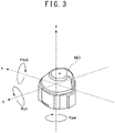
- FIG. 3 is a perspective view of the monitoring device MD.
- a rotation axis line direction is made a Y direction
- a direction orthogonal to the Y direction and facing the front of the monitoring device MD is made a Z direction
- a direction orthogonal to each of the Y direction and the Z direction is made an X direction.
- YAW a yawing angle
- ROLL a rolling angle
- PITCH a pitching angle
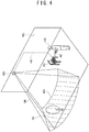
- FIG. 4 is an illustration showing an installation state of the monitoring device MD
- FIG. 5 is an illustration showing a personal computer that displays a measurement point marker group.
- the processing circuit PROC of the monitoring device MD is connected to the personal computer PC with wiring HS.
- a controller (user interface) AC equipped with an analog input section, such as a joystick capable of being operated by a user US, is connected.
- the monitoring device MD, the personal computer PC, and the controller AC constitute a monitoring system.
- the monitoring device MD is installed on the wall WL in a state where it looks down from an upper portion obliquely at a predetermined angle. Therefore, the monitoring range of the monitoring device MD is a range shaped in the form of a sector as shown with hatching in FIG. 4 . This is made a background BG.
- a background BG is an irradiation range of a light flux, but can estimate which area is being irradiated, from the orientation of the monitoring device MD. While visually comparing the display DPL of the personal computer PC as a display device with a ground surface being an almost horizontal surface including a background BG, the user US applies a virtual space including a displayed measurement point marker group to the actual background by operating the controller AC.
- the monitoring device MD Since the monitoring device MD does not have a position sensor etc., in the state of being installed on the side surface of the wall WL, it is not possible to detect a self-attitude. Then, by using the measurement point marker group output from the monitoring device MD, it is assumed that the virtual space is applied to an actual background. In the case of describing more concretely, the monitoring device MD detects the actual background BG (here, the ground surface) in an initial state.
- the signals processed by the processing circuit PROC are transmitted to the personal computer PC via the wiring HS, and are displayed on the display DPL as a measurement point marker group in a virtual space. For the displayed virtual space, the user US can perform rotation, parallel movement, viewpoint movement, etc. arbitrarily via the operation button and lever of the controller AC.
- the measurement point marker group is displayed with different colors correspondingly to a distance to a measurement point such that, for example, a measurement point distant from the monitoring device MD is displayed with blue and a measurement near to the monitoring device MD is displayed with red.
- a measurement point marker group may be provided with different colors correspondingly to the intensity of light reflected from a measurement point.
- the shape of a measurement marker is the same as the actual shape of a laser spot, it may be, for example, an arbitrary shape such as a square, a circle, an asterisk, or the like.
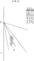
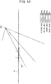
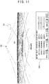
- FIG. 6 to FIG. 11 each is an illustration showing an example of a measurement point marker group on a virtual space displayed on the display DPL
- a numerical value (10 m) in the illustration represents a distance from the monitoring device MD in a reference manner.
- FIG. 6 shows a state viewed from the monitoring device MD along the Z direction by the input of the controller AC.
- the values of a yawing angle, a rolling angle, a pitching angle, and a height offset of a virtual space are indicated on the lower right portion of the display DPL, in FIG. 6 , all the values are made zero, because they are an initial state. These values change in accordance with temporary information input described in the below, and support adjustment by the user US.
- the user US can presume from its orientation that the top and bottom in the Y direction are reversed.
- the matter that the monitoring device MD is installed upside down is clear by checking its installed condition. Accordingly, from the above matter, it is possible to presume that the top and bottom in the Y direction are reversed.
- the matter that the background BG is almost a horizontal plane it may be presumed that the top and bottom in the Y direction are reversed.
- the personal computer PC performs coordinate conversion, and displays the measurement point marker group MK in a state where the top and bottom in the Y direction have become reversed as shown in FIG. 7 .
- "temporary installation information" used in here means to make the top and bottom of the virtual space including a measurement point marker group reversed (rotate).
- the user US adjusts the controller AC finely, and adjusts the attitude of the measurement point marker group MK.
- the rolling angle of the virtual space has become -180 degrees relative to the initial state.
- the display DPL displays the measurement point marker group MK shown in FIG. 8 . Since the user US who has visually compared the indication shown in FIG. 8 with the background BG, recognizes that the background BG is an almost horizontal plane, it can be presumed clearly that the virtual space inclines. Then, if the user US operates the controller AC and instructs to change the pitching angle of the virtual space together with the measurement point marker group (relative to the attitude of an object (background BG) actually existing in the monitoring space, inputs temporary attitude information so as to make the attitude of the measurement point marker group MK corresponding to it in the virtual space, follow).
- the personal computer PC performs coordinate conversion, and displays the measurement point marker group MK in a state where the inclination is returned so as to make the measurement point marker group MK horizontal as shown in FIG. 9 .
- "temporary attitude information" used in here means to change (rotate) the pitching angle of the virtual space including a measurement point marker group.
- the user US adjusts the controller AC finely, and adjusts the attitude of the measurement point marker group MK.
- the pitching angle of the virtual space has become - 22.2 degrees relative to the initial state.
- the user US who has visually compared the indication shown in FIG. 9 with the background BG recognizes that the background BG is the ground surface, it can be determined that it is too low relative to the horizontal plane (reference plane) based on the monitoring device MD itself in the virtual space.
- the personal computer PC performs coordinate conversion, and displays the measurement point marker group MK in a state where the measurement point marker group MK has been moved in parallel relatively as shown in FIG. 10 . That is, "temporary attitude information" used in here means to shift the measurement point marker group in the virtual space.
- the user US While looking at the displayed measurement point marker group MK, the user US adjusts the controller AC finely, and adjusts the position of the measurement point marker group MK.
- the height offset of the virtual space has become +12.5 m relative to the initial state.
- the three-dimensional data of the virtual space having been subjected to the coordinate conversion in this way are memorized in a nonvolatile memory HDD built in the processing circuit PROC in Fig. 12 , and are used when a monitoring image is displayed on a monitor (not illustrated) at the time of actual monitoring.
- the user US sets a monitoring region by operating the controller AC.
- the user US instructs viewpoint movement (change of the position of a viewpoint) so as to see the monitoring device MD from the background side along the Z direction.
- the display DPL displays the measurement point marker group as shown in FIG. 11 on the basis of the changed position of the viewpoint.
- a box-like monitoring region DA in here, a dotted line is displayed at a diagonally upper right position on a screen.
- the user US inputs the setting data of the monitoring region DA via the controller AC.
- numerical values within an information column INFO that is displayed on the display DPL and shows the setting data of the monitoring region DA may be made to be changed in accordance with the input from the controller AC.
- the user US may be made to input directly the numerical values via a key board, a mouse, etc. instead of the controller AC.
- the user US while looking at the displayed measurement point marker group MK, the user US can apply the virtual space of the monitoring device MD to the actual background BG intuitively and easily by using the controller AC. Furthermore, while comparing with the actual background BG, the user US can set the monitoring region DA at a desired position intuitively and easily.
- the processing circuit PROC determines that the probability of invasion into a facility etc, is high, successively, issues an emergency alarm signal or the like, and perform alarm indication on a monitor not illustrated, whereby it is possible to arouse attention.
- an input of temporary attitude information may be performed so as to make the attitude and position of a measurement point marker group follow relative to the attitude and position of a wall surface, a standing tree, or the like as a vertical surface actually existing in a monitoring space.
- the monitoring region DA to be set up is made the shape of a box, it can be made various shapes, such as a spherical shape, a ring, or a boundary line.
- the number of the monitoring regions DA capable of being set up may be plural without being limited to a single number.
Landscapes
- Physics & Mathematics (AREA)
- Engineering & Computer Science (AREA)
- General Physics & Mathematics (AREA)
- General Engineering & Computer Science (AREA)
- Electromagnetism (AREA)
- Theoretical Computer Science (AREA)
- General Life Sciences & Earth Sciences (AREA)
- Life Sciences & Earth Sciences (AREA)
- Optics & Photonics (AREA)
- Geophysics (AREA)
- Human Computer Interaction (AREA)
- Computer Networks & Wireless Communication (AREA)
- Radar, Positioning & Navigation (AREA)
- Remote Sensing (AREA)
- Optical Radar Systems And Details Thereof (AREA)
- Burglar Alarm Systems (AREA)
Claims (4)
- Système de surveillance comprenant:une unité de projection et de réception de lumière comprenant une section d'émission (LPS) pour émettre un flux de lumière, une section de balayage pour balayer le flux de lumière dans un espace de surveillance et une section de réception de lumière (RPS) pour recevoir un flux de lumière réfléchi par un objet dans l'espace de surveillance ;une section de traitement pour mesurer une distance de l'objet en traitant des signaux de l'unité de projection et de réception de lumière et pour sortir une image de distance de la région entière dans l'espace de surveillance dans un espace virtuel avec des informations de distance tridimensionnelles pour chaque point de mesure de l'image de distance ;une interface d'utilisateur pour fixer une région de surveillance (DA) dans l'espace virtuel par une action d'un utilisateur ; etun dispositif d'affichage, qui, après que la région de surveillance (DA) ait été fixée par l'interface d'utilisateur , affiche la région de surveillance fixée (DA) ensemble avec l'image de distance,dans lequel la section de traitement sort un signal d'alerte, si un objet entre dans la région de surveillance (DA) pendant la surveillance.
- Système de surveillance selon la revendication 1, caractérisé en ce que l'entrée d'une information d'attitude est rendue possible par moyen de l'interface d'utilisateur pour régler une attitude ou une position de l'image de distance à afficher sur le dispositif d'affichage, et le dispositif d'affichage effectue une conversion de coordonnés au moins par rapport à l'image de distance sur la base de l'information d'attitude entrée et il affiche l'image de distance dans l'espace virtuel après que l'image ait été soumise à la conversion de coordonnés.
- Système de surveillance selon la revendication 1 ou la revendication 2, caractérisé en ce que l'image de distance est affichée avec une couleur différente en correspondance avec une distance ou une intensité de lumière réfléchie du point de mesure.
- Système de surveillance selon l'une quelconque des revendications 1 à 3, caractérisé en ce que, si une instruction de changer une position de point de vue à une position de point de vue changée par moyen de l'interface d'utilisateur a été effectuée, le dispositif d'affichage affiche l'image de distance à la position de point de vue changée.
Applications Claiming Priority (2)
| Application Number | Priority Date | Filing Date | Title |
|---|---|---|---|
| JP2016098629 | 2016-05-17 | ||
| PCT/JP2017/017470 WO2017199786A1 (fr) | 2016-05-17 | 2017-05-09 | Système de surveillance |
Publications (3)
| Publication Number | Publication Date |
|---|---|
| EP3460773A1 EP3460773A1 (fr) | 2019-03-27 |
| EP3460773A4 EP3460773A4 (fr) | 2019-05-22 |
| EP3460773B1 true EP3460773B1 (fr) | 2021-09-22 |
Family
ID=60325941
Family Applications (1)
| Application Number | Title | Priority Date | Filing Date |
|---|---|---|---|
| EP17799211.2A Active EP3460773B1 (fr) | 2016-05-17 | 2017-05-09 | Système de surveillance |
Country Status (4)
| Country | Link |
|---|---|
| US (1) | US11199627B2 (fr) |
| EP (1) | EP3460773B1 (fr) |
| JP (1) | JP6825624B2 (fr) |
| WO (1) | WO2017199786A1 (fr) |
Families Citing this family (4)
| Publication number | Priority date | Publication date | Assignee | Title |
|---|---|---|---|---|
| CN110927731B (zh) * | 2019-11-15 | 2021-12-17 | 深圳市镭神智能系统有限公司 | 一种立体防护方法、三维检测装置和计算机可读存储介质 |
| US11935377B1 (en) * | 2021-06-03 | 2024-03-19 | Ambarella International Lp | Security cameras integrating 3D sensing for virtual security zone |
| US12292568B2 (en) * | 2021-12-08 | 2025-05-06 | Focuslight Technologies Inc. | Light spot scanning device, scanning method thereof, and medical cosmetology device |
| CN119392941B (zh) * | 2025-01-03 | 2025-04-11 | 北京建工集团有限责任公司 | 一种基于三点定位姿态监测的拱形结构施工方法 |
Family Cites Families (11)
| Publication number | Priority date | Publication date | Assignee | Title |
|---|---|---|---|---|
| EP0845765A1 (fr) * | 1996-12-02 | 1998-06-03 | Cerberus Ag | Système de détection d'intrusions |
| JP2001183461A (ja) * | 1999-12-27 | 2001-07-06 | Minolta Co Ltd | 距離測定装置 |
| JP4727388B2 (ja) | 2005-10-28 | 2011-07-20 | セコム株式会社 | 侵入検知装置 |
| US8294881B2 (en) * | 2008-08-26 | 2012-10-23 | Honeywell International Inc. | Security system using LADAR-based sensors |
| JP2011002339A (ja) * | 2009-06-18 | 2011-01-06 | Panasonic Electric Works Co Ltd | 物体検知装置 |
| JP2011185664A (ja) | 2010-03-05 | 2011-09-22 | Panasonic Electric Works Co Ltd | 対象物検出装置 |
| JP5779816B2 (ja) * | 2010-10-25 | 2015-09-16 | オプテックス株式会社 | 検知エリア表示装置、検知エリア表示方法、検知エリア表示プログラムおよび検知エリア表示プログラムを記録した記録媒体 |
| JP5549631B2 (ja) | 2011-03-31 | 2014-07-16 | 株式会社デンソーウェーブ | 携帯型設定端末、及び監視システム |
| US9707892B2 (en) * | 2012-04-25 | 2017-07-18 | Gentex Corporation | Multi-focus optical system |
| JP6045865B2 (ja) * | 2012-09-20 | 2016-12-14 | 住友建機株式会社 | ショベル |
| DE102013114821B3 (de) * | 2013-12-23 | 2014-10-23 | Jenoptik Robot Gmbh | Verfahren zur Ausrichtung eines Laserscanners zu einer Fahrbahn |
-
2017
- 2017-05-09 US US16/300,403 patent/US11199627B2/en active Active
- 2017-05-09 EP EP17799211.2A patent/EP3460773B1/fr active Active
- 2017-05-09 WO PCT/JP2017/017470 patent/WO2017199786A1/fr not_active Ceased
- 2017-05-09 JP JP2018518227A patent/JP6825624B2/ja active Active
Also Published As
| Publication number | Publication date |
|---|---|
| US11199627B2 (en) | 2021-12-14 |
| WO2017199786A1 (fr) | 2017-11-23 |
| EP3460773A4 (fr) | 2019-05-22 |
| EP3460773A1 (fr) | 2019-03-27 |
| JP6825624B2 (ja) | 2021-02-03 |
| US20190094365A1 (en) | 2019-03-28 |
| JPWO2017199786A1 (ja) | 2019-03-14 |
Similar Documents
| Publication | Publication Date | Title |
|---|---|---|
| EP2722645B1 (fr) | Dispositif et système de mesure tridimensionnelle | |
| US9618620B2 (en) | Using depth-camera images to speed registration of three-dimensional scans | |
| JP5688876B2 (ja) | レーザスキャナ測定システムの較正方法 | |
| US11004250B2 (en) | Point cloud data display system | |
| EP3460773B1 (fr) | Système de surveillance | |
| US12008783B2 (en) | Reality capture device | |
| JP7064163B2 (ja) | 3次元情報取得システム | |
| US20080306708A1 (en) | System and method for orientation and location calibration for image sensors | |
| JP2019101000A (ja) | 測距点群データ測定システム、および制御プログラム | |
| CN115127528A (zh) | 测量系统 | |
| CN108814452A (zh) | 扫地机器人及其障碍检测方法 | |
| US20240112327A1 (en) | Bar arrangement inspection system and bar arrangement inspection method | |
| EP3460772B1 (fr) | Procédé de réglage de système de surveillance et système de surveillance | |
| CZ306524B6 (cs) | Metoda monitorování pomocí kamerového systému s prostorovou detekcí pohybu | |
| US20230342952A1 (en) | Method for coordinative measuring by terrestrial scanning with image-based interference detection of moving objects | |
| JP2004210045A (ja) | 監視装置 | |
| US11009887B2 (en) | Systems and methods for remote visual inspection of a closed space | |
| JP4880925B2 (ja) | 設定装置 | |
| JP2003075148A (ja) | デジタルスチルカメラを用いた変位計測装置 | |
| US12253601B2 (en) | Three-dimensional survey apparatus, three-dimensional survey method, and three-dimensional survey program | |
| US20250383201A1 (en) | Surveying system and surveying method | |
| US20240219542A1 (en) | Auto-level step for extrinsic calibration | |
| KR102229069B1 (ko) | 복합 센서 기반의 전자 안전펜스를 이용한 안전 관리 시스템 및 안전 관리 방법 | |
| JP2018005737A (ja) | 物体検出センサ及び監視システム | |
| WO2025238864A1 (fr) | Dispositif de surveillance |
Legal Events
| Date | Code | Title | Description |
|---|---|---|---|
| STAA | Information on the status of an ep patent application or granted ep patent |
Free format text: STATUS: THE INTERNATIONAL PUBLICATION HAS BEEN MADE |
|
| PUAI | Public reference made under article 153(3) epc to a published international application that has entered the european phase |
Free format text: ORIGINAL CODE: 0009012 |
|
| STAA | Information on the status of an ep patent application or granted ep patent |
Free format text: STATUS: REQUEST FOR EXAMINATION WAS MADE |
|
| 17P | Request for examination filed |
Effective date: 20181031 |
|
| AK | Designated contracting states |
Kind code of ref document: A1 Designated state(s): AL AT BE BG CH CY CZ DE DK EE ES FI FR GB GR HR HU IE IS IT LI LT LU LV MC MK MT NL NO PL PT RO RS SE SI SK SM TR |
|
| AX | Request for extension of the european patent |
Extension state: BA ME |
|
| A4 | Supplementary search report drawn up and despatched |
Effective date: 20190425 |
|
| RIC1 | Information provided on ipc code assigned before grant |
Ipc: G08B 13/187 20060101AFI20190417BHEP |
|
| DAV | Request for validation of the european patent (deleted) | ||
| DAX | Request for extension of the european patent (deleted) | ||
| STAA | Information on the status of an ep patent application or granted ep patent |
Free format text: STATUS: EXAMINATION IS IN PROGRESS |
|
| 17Q | First examination report despatched |
Effective date: 20200424 |
|
| GRAP | Despatch of communication of intention to grant a patent |
Free format text: ORIGINAL CODE: EPIDOSNIGR1 |
|
| STAA | Information on the status of an ep patent application or granted ep patent |
Free format text: STATUS: GRANT OF PATENT IS INTENDED |
|
| INTG | Intention to grant announced |
Effective date: 20210422 |
|
| GRAS | Grant fee paid |
Free format text: ORIGINAL CODE: EPIDOSNIGR3 |
|
| GRAA | (expected) grant |
Free format text: ORIGINAL CODE: 0009210 |
|
| STAA | Information on the status of an ep patent application or granted ep patent |
Free format text: STATUS: THE PATENT HAS BEEN GRANTED |
|
| AK | Designated contracting states |
Kind code of ref document: B1 Designated state(s): AL AT BE BG CH CY CZ DE DK EE ES FI FR GB GR HR HU IE IS IT LI LT LU LV MC MK MT NL NO PL PT RO RS SE SI SK SM TR |
|
| REG | Reference to a national code |
Ref country code: GB Ref legal event code: FG4D |
|
| REG | Reference to a national code |
Ref country code: IE Ref legal event code: FG4D |
|
| REG | Reference to a national code |
Ref country code: DE Ref legal event code: R096 Ref document number: 602017046458 Country of ref document: DE |
|
| REG | Reference to a national code |
Ref country code: CH Ref legal event code: EP Ref country code: AT Ref legal event code: REF Ref document number: 1432916 Country of ref document: AT Kind code of ref document: T Effective date: 20211015 |
|
| REG | Reference to a national code |
Ref country code: LT Ref legal event code: MG9D |
|
| REG | Reference to a national code |
Ref country code: NL Ref legal event code: MP Effective date: 20210922 |
|
| PG25 | Lapsed in a contracting state [announced via postgrant information from national office to epo] |
Ref country code: HR Free format text: LAPSE BECAUSE OF FAILURE TO SUBMIT A TRANSLATION OF THE DESCRIPTION OR TO PAY THE FEE WITHIN THE PRESCRIBED TIME-LIMIT Effective date: 20210922 Ref country code: FI Free format text: LAPSE BECAUSE OF FAILURE TO SUBMIT A TRANSLATION OF THE DESCRIPTION OR TO PAY THE FEE WITHIN THE PRESCRIBED TIME-LIMIT Effective date: 20210922 Ref country code: SE Free format text: LAPSE BECAUSE OF FAILURE TO SUBMIT A TRANSLATION OF THE DESCRIPTION OR TO PAY THE FEE WITHIN THE PRESCRIBED TIME-LIMIT Effective date: 20210922 Ref country code: RS Free format text: LAPSE BECAUSE OF FAILURE TO SUBMIT A TRANSLATION OF THE DESCRIPTION OR TO PAY THE FEE WITHIN THE PRESCRIBED TIME-LIMIT Effective date: 20210922 Ref country code: NO Free format text: LAPSE BECAUSE OF FAILURE TO SUBMIT A TRANSLATION OF THE DESCRIPTION OR TO PAY THE FEE WITHIN THE PRESCRIBED TIME-LIMIT Effective date: 20211222 Ref country code: LT Free format text: LAPSE BECAUSE OF FAILURE TO SUBMIT A TRANSLATION OF THE DESCRIPTION OR TO PAY THE FEE WITHIN THE PRESCRIBED TIME-LIMIT Effective date: 20210922 Ref country code: BG Free format text: LAPSE BECAUSE OF FAILURE TO SUBMIT A TRANSLATION OF THE DESCRIPTION OR TO PAY THE FEE WITHIN THE PRESCRIBED TIME-LIMIT Effective date: 20211222 |
|
| REG | Reference to a national code |
Ref country code: AT Ref legal event code: MK05 Ref document number: 1432916 Country of ref document: AT Kind code of ref document: T Effective date: 20210922 |
|
| PG25 | Lapsed in a contracting state [announced via postgrant information from national office to epo] |
Ref country code: LV Free format text: LAPSE BECAUSE OF FAILURE TO SUBMIT A TRANSLATION OF THE DESCRIPTION OR TO PAY THE FEE WITHIN THE PRESCRIBED TIME-LIMIT Effective date: 20210922 Ref country code: GR Free format text: LAPSE BECAUSE OF FAILURE TO SUBMIT A TRANSLATION OF THE DESCRIPTION OR TO PAY THE FEE WITHIN THE PRESCRIBED TIME-LIMIT Effective date: 20211223 |
|
| PG25 | Lapsed in a contracting state [announced via postgrant information from national office to epo] |
Ref country code: AT Free format text: LAPSE BECAUSE OF FAILURE TO SUBMIT A TRANSLATION OF THE DESCRIPTION OR TO PAY THE FEE WITHIN THE PRESCRIBED TIME-LIMIT Effective date: 20210922 |
|
| PG25 | Lapsed in a contracting state [announced via postgrant information from national office to epo] |
Ref country code: IS Free format text: LAPSE BECAUSE OF FAILURE TO SUBMIT A TRANSLATION OF THE DESCRIPTION OR TO PAY THE FEE WITHIN THE PRESCRIBED TIME-LIMIT Effective date: 20220122 Ref country code: SK Free format text: LAPSE BECAUSE OF FAILURE TO SUBMIT A TRANSLATION OF THE DESCRIPTION OR TO PAY THE FEE WITHIN THE PRESCRIBED TIME-LIMIT Effective date: 20210922 Ref country code: RO Free format text: LAPSE BECAUSE OF FAILURE TO SUBMIT A TRANSLATION OF THE DESCRIPTION OR TO PAY THE FEE WITHIN THE PRESCRIBED TIME-LIMIT Effective date: 20210922 Ref country code: PT Free format text: LAPSE BECAUSE OF FAILURE TO SUBMIT A TRANSLATION OF THE DESCRIPTION OR TO PAY THE FEE WITHIN THE PRESCRIBED TIME-LIMIT Effective date: 20220124 Ref country code: PL Free format text: LAPSE BECAUSE OF FAILURE TO SUBMIT A TRANSLATION OF THE DESCRIPTION OR TO PAY THE FEE WITHIN THE PRESCRIBED TIME-LIMIT Effective date: 20210922 Ref country code: NL Free format text: LAPSE BECAUSE OF FAILURE TO SUBMIT A TRANSLATION OF THE DESCRIPTION OR TO PAY THE FEE WITHIN THE PRESCRIBED TIME-LIMIT Effective date: 20210922 Ref country code: ES Free format text: LAPSE BECAUSE OF FAILURE TO SUBMIT A TRANSLATION OF THE DESCRIPTION OR TO PAY THE FEE WITHIN THE PRESCRIBED TIME-LIMIT Effective date: 20210922 Ref country code: EE Free format text: LAPSE BECAUSE OF FAILURE TO SUBMIT A TRANSLATION OF THE DESCRIPTION OR TO PAY THE FEE WITHIN THE PRESCRIBED TIME-LIMIT Effective date: 20210922 Ref country code: CZ Free format text: LAPSE BECAUSE OF FAILURE TO SUBMIT A TRANSLATION OF THE DESCRIPTION OR TO PAY THE FEE WITHIN THE PRESCRIBED TIME-LIMIT Effective date: 20210922 Ref country code: AL Free format text: LAPSE BECAUSE OF FAILURE TO SUBMIT A TRANSLATION OF THE DESCRIPTION OR TO PAY THE FEE WITHIN THE PRESCRIBED TIME-LIMIT Effective date: 20210922 |
|
| REG | Reference to a national code |
Ref country code: DE Ref legal event code: R097 Ref document number: 602017046458 Country of ref document: DE |
|
| PG25 | Lapsed in a contracting state [announced via postgrant information from national office to epo] |
Ref country code: DK Free format text: LAPSE BECAUSE OF FAILURE TO SUBMIT A TRANSLATION OF THE DESCRIPTION OR TO PAY THE FEE WITHIN THE PRESCRIBED TIME-LIMIT Effective date: 20210922 |
|
| PLBE | No opposition filed within time limit |
Free format text: ORIGINAL CODE: 0009261 |
|
| STAA | Information on the status of an ep patent application or granted ep patent |
Free format text: STATUS: NO OPPOSITION FILED WITHIN TIME LIMIT |
|
| 26N | No opposition filed |
Effective date: 20220623 |
|
| PG25 | Lapsed in a contracting state [announced via postgrant information from national office to epo] |
Ref country code: SI Free format text: LAPSE BECAUSE OF FAILURE TO SUBMIT A TRANSLATION OF THE DESCRIPTION OR TO PAY THE FEE WITHIN THE PRESCRIBED TIME-LIMIT Effective date: 20210922 |
|
| REG | Reference to a national code |
Ref country code: CH Ref legal event code: PL |
|
| REG | Reference to a national code |
Ref country code: BE Ref legal event code: MM Effective date: 20220531 |
|
| PG25 | Lapsed in a contracting state [announced via postgrant information from national office to epo] |
Ref country code: MC Free format text: LAPSE BECAUSE OF FAILURE TO SUBMIT A TRANSLATION OF THE DESCRIPTION OR TO PAY THE FEE WITHIN THE PRESCRIBED TIME-LIMIT Effective date: 20210922 Ref country code: LU Free format text: LAPSE BECAUSE OF NON-PAYMENT OF DUE FEES Effective date: 20220509 Ref country code: LI Free format text: LAPSE BECAUSE OF NON-PAYMENT OF DUE FEES Effective date: 20220531 Ref country code: IT Free format text: LAPSE BECAUSE OF FAILURE TO SUBMIT A TRANSLATION OF THE DESCRIPTION OR TO PAY THE FEE WITHIN THE PRESCRIBED TIME-LIMIT Effective date: 20210922 Ref country code: CH Free format text: LAPSE BECAUSE OF NON-PAYMENT OF DUE FEES Effective date: 20220531 |
|
| PG25 | Lapsed in a contracting state [announced via postgrant information from national office to epo] |
Ref country code: IE Free format text: LAPSE BECAUSE OF NON-PAYMENT OF DUE FEES Effective date: 20220509 |
|
| PG25 | Lapsed in a contracting state [announced via postgrant information from national office to epo] |
Ref country code: BE Free format text: LAPSE BECAUSE OF NON-PAYMENT OF DUE FEES Effective date: 20220531 |
|
| P01 | Opt-out of the competence of the unified patent court (upc) registered |
Effective date: 20230510 |
|
| PG25 | Lapsed in a contracting state [announced via postgrant information from national office to epo] |
Ref country code: HU Free format text: LAPSE BECAUSE OF FAILURE TO SUBMIT A TRANSLATION OF THE DESCRIPTION OR TO PAY THE FEE WITHIN THE PRESCRIBED TIME-LIMIT; INVALID AB INITIO Effective date: 20170509 |
|
| PG25 | Lapsed in a contracting state [announced via postgrant information from national office to epo] |
Ref country code: SM Free format text: LAPSE BECAUSE OF FAILURE TO SUBMIT A TRANSLATION OF THE DESCRIPTION OR TO PAY THE FEE WITHIN THE PRESCRIBED TIME-LIMIT Effective date: 20210922 Ref country code: MK Free format text: LAPSE BECAUSE OF FAILURE TO SUBMIT A TRANSLATION OF THE DESCRIPTION OR TO PAY THE FEE WITHIN THE PRESCRIBED TIME-LIMIT Effective date: 20210922 Ref country code: CY Free format text: LAPSE BECAUSE OF FAILURE TO SUBMIT A TRANSLATION OF THE DESCRIPTION OR TO PAY THE FEE WITHIN THE PRESCRIBED TIME-LIMIT Effective date: 20210922 |
|
| PG25 | Lapsed in a contracting state [announced via postgrant information from national office to epo] |
Ref country code: MT Free format text: LAPSE BECAUSE OF FAILURE TO SUBMIT A TRANSLATION OF THE DESCRIPTION OR TO PAY THE FEE WITHIN THE PRESCRIBED TIME-LIMIT Effective date: 20210922 |
|
| PGFP | Annual fee paid to national office [announced via postgrant information from national office to epo] |
Ref country code: DE Payment date: 20250311 Year of fee payment: 9 |
|
| PG25 | Lapsed in a contracting state [announced via postgrant information from national office to epo] |
Ref country code: TR Free format text: LAPSE BECAUSE OF FAILURE TO SUBMIT A TRANSLATION OF THE DESCRIPTION OR TO PAY THE FEE WITHIN THE PRESCRIBED TIME-LIMIT Effective date: 20210922 |
|
| PGFP | Annual fee paid to national office [announced via postgrant information from national office to epo] |
Ref country code: GB Payment date: 20260313 Year of fee payment: 10 |
|
| PGFP | Annual fee paid to national office [announced via postgrant information from national office to epo] |
Ref country code: FR Payment date: 20260309 Year of fee payment: 10 |