EP3460938A1 - Appareil de protection contre les surtensions à coupure rapide empêchant l'arc - Google Patents
Appareil de protection contre les surtensions à coupure rapide empêchant l'arc Download PDFInfo
- Publication number
- EP3460938A1 EP3460938A1 EP17798643.7A EP17798643A EP3460938A1 EP 3460938 A1 EP3460938 A1 EP 3460938A1 EP 17798643 A EP17798643 A EP 17798643A EP 3460938 A1 EP3460938 A1 EP 3460938A1
- Authority
- EP
- European Patent Office
- Prior art keywords
- electrode
- arc
- preventing
- catapult
- protection device
- Prior art date
- Legal status (The legal status is an assumption and is not a legal conclusion. Google has not performed a legal analysis and makes no representation as to the accuracy of the status listed.)
- Granted
Links
Images








Classifications
-
- H—ELECTRICITY
- H01—ELECTRIC ELEMENTS
- H01C—RESISTORS
- H01C7/00—Non-adjustable resistors formed as one or more layers or coatings; Non-adjustable resistors made from powdered conducting material or powdered semi-conducting material with or without insulating material
- H01C7/10—Non-adjustable resistors formed as one or more layers or coatings; Non-adjustable resistors made from powdered conducting material or powdered semi-conducting material with or without insulating material voltage responsive, i.e. varistors
- H01C7/12—Overvoltage protection resistors; Arresters
-
- H—ELECTRICITY
- H02—GENERATION; CONVERSION OR DISTRIBUTION OF ELECTRIC POWER
- H02H—EMERGENCY PROTECTIVE CIRCUIT ARRANGEMENTS
- H02H9/00—Emergency protective circuit arrangements for limiting excess current or voltage without disconnection
- H02H9/08—Limitation or suppression of earth fault currents, e.g. Petersen coil
-
- H—ELECTRICITY
- H01—ELECTRIC ELEMENTS
- H01H—ELECTRIC SWITCHES; RELAYS; SELECTORS; EMERGENCY PROTECTIVE DEVICES
- H01H85/00—Protective devices in which the current flows through a part of fusible material and this current is interrupted by displacement of the fusible material when this current becomes excessive
- H01H85/02—Details
- H01H85/38—Means for extinguishing or suppressing arc
-
- H—ELECTRICITY
- H01—ELECTRIC ELEMENTS
- H01C—RESISTORS
- H01C1/00—Details
- H01C1/14—Terminals or tapping points specially adapted for resistors; Arrangements of terminals or tapping points on resistors
- H01C1/144—Terminals or tapping points specially adapted for resistors; Arrangements of terminals or tapping points on resistors the terminals or tapping points being welded or soldered
-
- H—ELECTRICITY
- H01—ELECTRIC ELEMENTS
- H01C—RESISTORS
- H01C7/00—Non-adjustable resistors formed as one or more layers or coatings; Non-adjustable resistors made from powdered conducting material or powdered semi-conducting material with or without insulating material
- H01C7/10—Non-adjustable resistors formed as one or more layers or coatings; Non-adjustable resistors made from powdered conducting material or powdered semi-conducting material with or without insulating material voltage responsive, i.e. varistors
-
- H—ELECTRICITY
- H01—ELECTRIC ELEMENTS
- H01H—ELECTRIC SWITCHES; RELAYS; SELECTORS; EMERGENCY PROTECTIVE DEVICES
- H01H85/00—Protective devices in which the current flows through a part of fusible material and this current is interrupted by displacement of the fusible material when this current becomes excessive
- H01H85/0039—Means for influencing the rupture process of the fusible element
- H01H85/0047—Heating means
-
- H—ELECTRICITY
- H01—ELECTRIC ELEMENTS
- H01H—ELECTRIC SWITCHES; RELAYS; SELECTORS; EMERGENCY PROTECTIVE DEVICES
- H01H85/00—Protective devices in which the current flows through a part of fusible material and this current is interrupted by displacement of the fusible material when this current becomes excessive
- H01H85/02—Details
- H01H85/0241—Structural association of a fuse and another component or apparatus
-
- H—ELECTRICITY
- H01—ELECTRIC ELEMENTS
- H01H—ELECTRIC SWITCHES; RELAYS; SELECTORS; EMERGENCY PROTECTIVE DEVICES
- H01H85/00—Protective devices in which the current flows through a part of fusible material and this current is interrupted by displacement of the fusible material when this current becomes excessive
- H01H85/02—Details
- H01H85/20—Bases for supporting the fuse; Separate parts thereof
-
- H—ELECTRICITY
- H01—ELECTRIC ELEMENTS
- H01H—ELECTRIC SWITCHES; RELAYS; SELECTORS; EMERGENCY PROTECTIVE DEVICES
- H01H85/00—Protective devices in which the current flows through a part of fusible material and this current is interrupted by displacement of the fusible material when this current becomes excessive
- H01H85/02—Details
- H01H85/30—Means for indicating condition of fuse structurally associated with the fuse
- H01H85/303—Movable indicating elements
- H01H85/306—Movable indicating elements acting on an auxiliary switch or contact
-
- H—ELECTRICITY
- H01—ELECTRIC ELEMENTS
- H01H—ELECTRIC SWITCHES; RELAYS; SELECTORS; EMERGENCY PROTECTIVE DEVICES
- H01H85/00—Protective devices in which the current flows through a part of fusible material and this current is interrupted by displacement of the fusible material when this current becomes excessive
- H01H85/02—Details
- H01H85/36—Means for applying mechanical tension to fusible member
-
- H—ELECTRICITY
- H02—GENERATION; CONVERSION OR DISTRIBUTION OF ELECTRIC POWER
- H02H—EMERGENCY PROTECTIVE CIRCUIT ARRANGEMENTS
- H02H3/00—Emergency protective circuit arrangements for automatic disconnection directly responsive to an undesired change from normal electric working condition with or without subsequent reconnection ; integrated protection
- H02H3/02—Details
- H02H3/04—Details with warning or supervision in addition to disconnection, e.g. for indicating that protective apparatus has functioned
Definitions
- the present invention relates to a circuit protection device, in particular to a surge protection device having functions of arc-preventing and fast-breaking under a short circuit and overloading current.
- Surge protectors or surge suppressors also known as surge protection device, provide protection against overvoltage for electronic components of various sensitive or expensive electronic devices, such as computers and communication-related equipment.
- the existing surge protection devices are usually designed for surge overvoltage protection under medium or general conditions, so when the surge overvoltage energy is small or lasting time is short, the surge protection device cannot be rapidly responsive.
- voltage-sensitive protection components such as piezoresistors
- Conventional varistors are electronic devices consisting of zinc oxide particles and complex intracrystalline particles, which are voltage nonlinear devices and ideal protection devices for sensitive electronic circuits due to the unique voltage and current characteristics.
- the existing surge protectors or surge suppressors with arc extinguishing function generally adopts method shielding and cutting off arc to extinguish arc.
- Chinese Patent No. 200810088691.X discloses a thermal protection piezoresistor module
- Chinese patent No. 201420145977.8 discloses a surge suppressor with arc extinguishing function, in which shielding and cutting off the arc is applied for thermally separating the switching electrode of the response switch assembly.
- the arc shielding mechanism needs a stroke to reach the position to shield and cut off the arc, and then the arcing shielding mechanism cannot enter the gap of the switch electrode to cut off the arc at the moment of switch separating. Therefore, the piezoresistor under the conditions will be instantaneously overloaded, overheat, thus finally causing fire and explosion. Such catastrophic damage will burn nearby sensitive electronic devices and components, leading the entire electronic system to collapse and damage.
- the object of the present invention is to overcome the defects and deficiencies of the existing surge protection device in situation of overvoltage leading to shout circuit and overload of the device, and provide a novel fast response surge protection device, which can effectively prevent arc generation and separate the surge protection device under shout circuit and overload, thus fire hazard can be fundamentally eliminated to ensure the safety of the electronic device.
- the present invention provides an arc-preventing fast-breaking surge protection device, wherein the device comprises an arc-preventing assembly, a voltage sensitive assembly, electrode pins, a response switch assembly and a housing consisted of an inner shell and an outer cover.
- the arc-preventing assembly comprises an arc-preventing catapult and an elastic element;
- the voltage sensitive assembly comprises at least one voltage sensitive element;
- the electrode pins comprising a flexible conductor, a first electrode pin and a second electrode pin;
- the response switch assembly comprises a thermosensitive element, a front electrode and a tripping electrode, the tripping electrode being consist of a movable electrode slice, a electrode welding end and a breaking section, the breaking section being respectively electrically connected the movable electrode slice and the electrode welding end.
- a first cavity and a second cavity are formed when the inner shall is engaged with the outer cover, and the arc-preventing assembly and the response switch assembly is arranged in the first cavity.
- the voltage sensitive element is consisted of sensitive components such as varistor sensitive component, discharge tubular sensitive component or discharge gap sensitive component, which is arranged in the second cavity.
- Two metal electrode slice are respectively disposed on both sides of the voltage sensitive element , and the front electrode is disposed on one of the metal electrode slices, the front electrode protrudes from the second cavity to the first cavity, the front electrode is provided with a slotted hole out of which the electrode welding end extends; the other metal electrode sheet is provided with a back electrode, the back electrode is in the second cavity
- a front end of the arc-preventing catapult is provided with a through hole out of which the electrode welding end protrudes; when the arc-preventing catapult contacts with the front electrode in the first cavity, the through hole faces the position of the slotted hole to ensure the electrode welding end protrudes to simultaneously pass through the through hole and the slotted hole.
- the breaking section is a metal alloy material which is vaporized instantaneously after melting, when an instantaneous surge overvoltage, an overcurrent, a short circuit current or an overload current through the tripping electrode exceeds a preset melting temperature, the breaking section of the tripping electrode instantaneously melts and vaporizes so that movable electrode slice separates from the electrode welding end, thus realizing fast breaking function of the surge protection device under a short circuit and an overload.
- the arc-preventing catapult is provided with an exhaust vent, when the tripping electrode is disposed in the arc-preventing catapult, the breaking section faces the position of the exhaust vent when the electrode welding end protrudes from the through hole, to ensure that the generated explosive gas wave can be discharged through the exhaust vent when the breaking section is melted and vaporized under the short circuit current or the overload current, and meanwhile, the effect of instantaneously stretching and blowing off the arc can be achieved by taking advantage of the gas wave.
- thermosensitive element is a fusible metal alloy solder, of which a temperature threshold for melting can be preset, and the thermosensitive element will melt rapidly when the preset temperature threshold is reached
- the arc-preventing fast-breaking surge protection device further comprises an indication module and a remote signaling alarm module for indicating a working state thereof.
- the indication module is an electrical indicating device, for example, a light emitting diode; or a mechanical indication module.
- the outer cover is provided with an indication window or indicating a working state of the surge protection device, then the surge protection device has functions of indicating a working state and sending remote signaling alarm.
- the first cavity is provided with an inserting groove, and the second cavity is provided with a blocking groove; the first electrode pin enters the first cavity through the inserting groove, and the second electrode pin enters the second cavity through the blocking groove; two ends of the flexible conductor are respectively electrically connected to the movable electrode slice and an inner end of the first electrode pin by metal alloy soldering or spot welding, the back electrode is electrically connected to an inner end of the first electrode pin by metal alloy soldering; an outer end of the first electrode pin and an outer end of the second electrode pin catapult outside the inner shells to form external connection pins.
- a normally closed working state Therefore, the response switch assembly and the voltage sensitive assembly are connected in series to form a normally closed working state, and the switch of the remote signaling device is not subjected to external stress under the normal working state of the surge protection device.
- the elastic element is consisted of a first elastic member and a second elastic member, and the first elastic member is disposed on the arc-preventing catapult, by which the movable electrode slice is misalighed; a second elastic member is disposed in the first cavity, by which the arc-preventing catapult is misalighed.
- the movable electrode slice is rapidly catapulted in the arc-preventing catapult due to an elastic stress of the first elastic member before the electrical arc generates; the arc-preventing catapult is rapidly catapulted in a direction away from the front electrode due to an elastic stress of the second compression spring.
- the molten thermosensitive element on the electrode welding end is scraped off by the through hole, a sufficiently large dielectric strength is formed between the through hole and the electrode welding end and between the front electrode and electrode welding end, and the tripping electrode and the front electrode are completely isolated from each other.
- the breaking section of the tripping electrode instantaneously melts and vaporizes so that movable electrode slice separates from the electrode welding end.
- the movable electrode slice is simultaneously catapulted in a direction away from the electrode welding end due to an elastic stress of the first elastic member and the second elastic member, the arc-preventing catapult is catapulted in a direction away from the front electrode due to an elastic stresses of the second elastic member, wherein the movable electrode slice is concealed in the arc-preventing catapult.
- a sufficiently large dielectric strength is formed between the electrode welding end and the movable electrode slice, completely avoiding the arc generated during separation of the movable electrode slice to form an electrical breakdown; in addition, the generated explosive gas wave can be discharged through the exhaust vent in the position of the breaking section and meanwhile, the effect of instantaneously stretching and blowing off the arc can be achieved by taking advantage of the gas wave.
- the working state of the response switch assembly is changed from normally closed to normally open.
- the indication module of the surge protection device is moved, the change from the indication window relative to the normal working state can be observed (for example, changing into a red display).
- the switch of the remote signaling alarm module is subjected to external stress, which causes the switch state to change, thereby sending an electrical signal for indicating protection invalidation of the surge protection device.
- the elastic stress of the first elastic member is usually preset to be larger than that of the second elastic member to ensure that the electrode welding end of the tripping electrode can be rapidly catapulted and kept concealed in the arc-preventing catapult at the detachment moment of the tripping electrode of the response switch assembly, thus sufficient insulation strength between the through hole and the tripping electrode will be kept.
- the arc-preventing fast-breaking surge protection device of the invention has the protection functions of catapulting and breaking under situations of transient temperature rising (such as the leakage current generated by the aging of its own life), the transient over-voltage, the transient short-circuit and the transient overload.
- the tripping electrode of the response switch assembly can be concealed; or when the catapulting and separating occur during the transient over-voltage, the transient short-circuit and the transient overload short circuit and overloading, the generated explosive gas wave during breaking of the tripping electrode can be stretched and further blow off the arc.
- the protection device can instantaneously realize breaking and concealing the tripping electrode, and an effective dielectric strength is formed before the arc is generated, completely preventing arc generation, which is not available in the exiting surge protection device.
- the surge protection device of the present invention does not limit the material types of the voltage sensitive element, the elastic element, the first elastic member, the second elastic member and the flexible conductor; in the following specific embodiments, as is taken as examples to describe in detail the structure of the surge protection device of the present invention, the elastic element 3 is compression springs 3, the first elastic member 3a is first compression springs 3a, the second elastic member 3b is second compression springs 3b, the voltage sensitive element 5 is a varistor 5, and the flexible conductor 7 is a flexible copper wire 7.
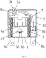
- an arc-preventing fast-breaking surge protection device comprises an inner shell 1, an outer cover 2, two first compression springs 3a, two second compression springs 3b, an arc-preventing catapult 4, a varistor 5, a flexible copper wire 7, a first electrode pin 8, a second electrode pin 9, an indication module 10, a remote signaling alarm module 20 and a tripping electrode 6;
- the tripping electrode 6 is consist of a movable electrode slice 6a, a electrode welding end 6b and a breaking section 6c, and the movable electrode slice 6a is electrically connected with the electrode welding end 6b through the breaking section 6c.
- Both of the back silver electrode and the front silver electrode of the varistor 5 are provided with metal electrode slices by way of soldering, wherein one metal electrode slice is provided with a front electrode 51, a slotted hole 51a out of which the electrode welding end 6b protrudes is formed on the front electrode 51; a back electrode 52 is formed by an extending bending portion of the other metal electrode slice.
- the inner shell 1 has a frame structure. When the inner shell 1 and the outer cover 2 are engaged by a buckle, a first cavity 1a formed on the front surface of the inner shell 1, and a second cavity 1b is formed on the back surface of the inner shell 1.
- the front electrode 51 protrudes into the first cavity 1a through the electrode hole 11 that penetrates the first cavity 1a and the second cavity 1b, as such, the slotted hole 51a is also located in the first cavity 1a; the back electrode 52 extends into the recess 12 on one side of the second cavity 1b.
- Two guide rails 13 perpendicular to the bottom of the inner shell 1 are disposed on both sides of the electrode hole 11 of the first cavity 1a, and the elongated slot openings of the two guide rails 13 are opposed to each other.
- An inserting groove 14 penetrating the bottom of the inner shell 1 is provided on the bottom of the side of the first cavity 1 farthest from the recess 12, a blocking groove15 with L-shape structure and penetrating the bottom of the inner shell 1 is disposed on the side of the second cavity 1b closest to the recess 12, and the inner end of the blocking groove is communicated with the recess 12.
- the arc-preventing catapult 4 with a box-like structure forms a cavity, and a spring groove 42 is provided on each side of the cavity.
- the front wall of the arc-preventing catapult 4 is provided with a through hole 42 out of which the electrode welding end 6b protrudes, and a wing arm 41 capable of being inserted into the guide rail 13 is provided on each side of the arc-preventing catapult 4.
- the arc-preventing catapult 4 slides along the guide rails 13 with the wing arm 41 of each side of the arc-preventing catapult 4 until touching the front electrode 51, as such, the positions of the through hole 4a and the slotted hole 51a face each other.
- the arc-preventing catapult 4 is further provided with an exhaust vent 4b.
- the breaking section 6c faces the exhaust vent 4b.
- the indication module 10 is a knockout pin which is disposed at the end of the arc-preventing catapult 4 and integral with the arc-preventing catapult 4.
- An indication window 2a is arranged in a corresponding position of the outer cover 2, out of which the indication module 10 may extends.
- the remote signaling alarm module 20 is an independent switch.
- the remote signaling alarm module 20 is disposed in the outer cover 2, of which an alarm pin 20a extends out of the outer cover 2.
- the two second compression springs 3b are respectively arranged in the two guide rails 13, and the arc-preventing catapult 4 is inserted into the guide rails 41 through the side wing arms 41 until touching the front electrode 51, and the two second compression springs 3b are in compressed state.
- the two first compression springs 3a are respectively arranged in the two spring grooves 42, and the tripping electrode 6 inserted into the arc-preventing catapult 4 until the electrode welding end 6b protrudes out of the through hole 4a and the slotted hole 51a, and the movable electrode slice 6a compresses the two first compression spring 3a to be in compressed state.
- the elastic stress of the first compression springs 3a is greater than the elastic stress of the second compression springs 3b.
- the electrode welding end 6b is electrically connected to the front electrode 51 through a thermosensitive element 30 by way of soldering; the first electrode pin 8 and the second electrode pin 9 are respectively fixed to the inner shell 1 through the inserting groove 14 and the blocking groove 15, and an outer end 8a of the first electrode pin 8 and an outer end 9a of the second electrode pin 9 extends outside the inner shell 1 to form external connection pins, and two ends of the flexible copper wire 7 are respectively electrically connected to the movable electrode slice 6a and an inner end 8b of the first electrode pin by metal alloy soldering or spot welding; the back electrode 52 is electrically connected to an inner end 9b of the first electrode pin 9 by metal alloy soldering, so that these electric conductors are connected in series with the varistor 5 to form a normally closed switch.
- the two external connection pins are respectively connected to the phase line and the neutral line or the ground line.
- the indication module 10 is located in the indication window 2a, and the switch of the remote signaling alarm module 20 is free from the compression of the external stress under the normal working state of the surge protection device.
- the electrode welding end 6b is rapidly catapulted in the arc-preventing catapult 4 due to elastic stresses of the two first compression springs 3a on the movable electrode slice 6a; simultaneously the arc-preventing catapult 4 is rapidly catapulted in a direction away from the front electrode 51 due to elastic stresses of the two second compression springs 3b.
- the indication module 10 extends out of the indication window 2a, and the switch of the remote signaling alarm module 20 is compressed to be stationary by ends of the movable electrode slice 6a and the arc-preventing catapult 4, thereby causing its switch state to change.
- a mechanical indication for invalidation is realized, meanwhile a remote signal for indicating fault of the surge protection device is sent out.
- a sufficiently large dielectric strength is formed between the electrode welding end 6b and the front electrode 51, and the tripping electrode 6 and the front electrode 51 are completely isolated from each other.
- the breaking section 6c of the tripping electrode instantaneously melts and vaporizes so that movable electrode slice 6a separates from the electrode welding end 6b.
- the movable electrode slice 6a and the arc-preventing catapult 4 are simultaneously catapulted in a direction away from the front electrode 51 due to the elastic stresses of the first compression springs 3a and the second first compression springs 3b.
- the indication module 10 extends out of the indication window 2a, and the switch of the remote signaling alarm module 20 is compressed to be stationary by ends of the movable electrode slice 6a and the arc-preventing catapult 4, thereby causing its switch state to change.
- a mechanical indication for invalidation is realized, meanwhile a remote signal for indicating failure of the surge protection device is sent out.
- the electrode welding end 6b separates from the movable electrode slice 6a.
- a sufficiently large dielectric strength is formed between the electrode welding end 6b and the movable electrode slice 6a, and the movable electrode slice 6a and the front electrode 51 are completely isolated from each other.
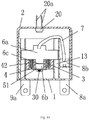
- FIG. 1 Another embodiment of an arc-preventing fast-breaking surge protection device of the present invention is as follows. This embodiment has similar structure and usage as most of the components of Embodiment 1, the main differences of them lie in the catapulting mode of the arc-preventing assembly, the structure of the tripping electrode 6 and the remote signaling alarm module 20 missing in the surge protection device.
- the arc-preventing catapult 4 has a cavity structure with an open top, and a T-shaped sliding groove 43 is formed on each side wall of the arc-preventing catapult 4, and the extending portion of each side of the movable electrode slice 6a of the tripping electrode 6 passes through the sliding groove 43 and extends out of the arc-preventing catapult 4, and a front wall of the arc-preventing catapult 4 is provided with a through hole 4a out of which the electrode welding end 6b extends.
- he indication module 10 is a knockout pin which is disposed at the end of the arc-preventing catapult 4 and integral with the arc-preventing catapult 4.
- FIG. 6 The structure shown in Fig. 6 is replaced with the corresponding structure in Fig. 3 .
- FIG. 7 two compression springs 3 are respectively placed in the two guide rails 13, and the extending portion of each side of the movable electrode slice 6a is inserted into the guide rail 13 and drives the arc-preventing catapult 4 until toughing the front electrode 51.
- the electrode welding end 6b protrudes out of the through hole 4a and the slotted hole 51a, and the movable electrode slice 6a presses the two compression springs 3 to be in compressed state.
- the electrode welding end 6b is electrically connected to the front electrode 51 through a thermosensitive element 30 by way of soldering.
- the two external connection pins are respectively connected to the phase line and the neutral line or the ground line.
- the indication module 10 is compressed in the indication window 2a under the normal working state of the surge protection device.
- thermosensitive element 30 when temperature of the varistor 5 is increased due to a short circuit current, an overloading current through circuits or a leakage current because of the aging of the varistor 5, the generated heat is transmitted to the front electrode 51, thus enabling the thermosensitive element 30 to melt when reaching a preset temperature threshold.
- the electrode welding end 6b is rapidly catapulted in the through hole 4a due to elastic stresses of the compression springs 3 on the movable electrode slice 6a; the extending portion of each side of the movable electrode slice slides to end of the sliding groove 43 and drives the arc-preventing catapult 4 to continuously catapult in a direction away from the front electrode 51.
- the indication module 10 extends out of the indication window 2a and is blocked to be stationary. As Such, a mechanical indication for invalidation is realized.
- a sufficiently large dielectric strength is formed between the electrode welding end 6b and the through hole 4a, the through hole 4a and the front electrode 51, and the tripping electrode 6 and the front electrode 6b are completely isolated from each other.
- the breaking section 6c of the tripping electrode 6 instantaneously melts and vaporizes so that movable electrode slice 6a separates from the electrode welding end 6b.
- the movable electrode slice 6a is catapulted in a direction away from the front electrode 51 due to the elastic stresses of the compression springs, and then the extending portion of each side of the movable electrode slice 6a slides to end of the sliding groove 43 and drives the arc-preventing catapult 4 to continuously catapult in a direction away from the front electrode 51.
- the indication module 10 extends out of the indication window 1a and is blocked to be stationary. As Such, a mechanical indication for invalidation is realized.
- a sufficiently large dielectric strength is formed between the electrode welding end 6b and the through hole 4a, the through hole 4a and the movable electrode slice 6a, and the movable electrode slice 6a and the front electrode are completely isolated from each other.
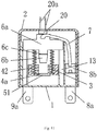
- FIG. 1 Another embodiment of an arc-preventing fast-breaking surge protection device of the present invention is as follows. This embodiment has similar structure and usage as most of the components of Embodiment 2, the main differences of them lie in the catapulting mode of the arc-preventing assembly and the indication module 10 and the indication window 1a missing in the surge protection device.
- the remote signaling alarm module 20 is disposed in the outer cover 2, of which an alarm pin 20a extends out of the outer cover 2.
- the arc-preventing catapult 4 is a baffle, which is vertically fixed under the electrode hole 11.
- the baffle is provided with a through hole 4a out of which the electrode welding end 6b protrudes, and a spring groove 42 is provided on each side of the through hole 4a.
- Two compression springs 3 are respectively arranged in the two spring grooves 42.
- each side of the movable electrode slice 6a is inserted into the guide rail 13 until the electrode welding end 6b protrudes out of the through hole 4a and the slotted hole 51a; the movable electrode piece 6a presses the two compression springs 3 to be in compressed state.
- the electrode welding end 6b is electrically connected to the front electrode 51 through a thermosensitive element 30 by way of soldering.
- the two external connection pins are respectively connected to the phase line and the neutral line or the ground line. As such, the switch of the remote signaling alarm module 20 is free from the compression of the external stress under the normal working state of the surge protection device.
- thermosensitive element 30 when temperature of the varistor 5 is increased due to a short circuit current, an overloading current through circuits or a leakage current because of the aging of the varistor 5, the generated heat is transmitted to the front electrode 51, thus enabling the thermosensitive element 30 to melt when reaching a preset temperature threshold.
- the electrode welding end 6b is rapidly catapulted in the through hole 4a by the movable electrode slice 6a due to an elastic stress of the compression springs 3 and catapulted continuously in a direction away from the front electrode 51.
- the switch of the remote signaling alarm module 20 is compressed to be stationary by end of the movable electrode slice 6a, thereby causing its switch state to change, and then a remote signal for indicating fault of the surge protection device is sent out.
- a sufficiently large dielectric strength is formed between the electrode welding end 6b and the through hole 4a, and the tripping electrode 6 and the front electrode 51 are completely isolated from each other.
- the breaking section 6c of the tripping electrode 6 instantaneously melts and vaporizes so that the movable electrode slice 6a separates from the electrode welding end 6b.
- the movable electrode slice 6a is catapulted in a direction away from the front electrode 51 due to the elastic stresses of the compression springs 3,
- the switch of the remote signaling alarm module 20 is compressed and blocked to be stationary by end of the movable electrode slice 6a, thereby causing its switch state to change,, then a remote signal for indication fault of the surge protection device is sent out.
- a sufficiently large dielectric strength is formed between the electrode welding end 6b and the movable electrode slice 6a, and the movable electrode slice 6a and the front electrode 51 are completely isolated from each other
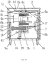
- Another embodiment of an arc-preventing fast-breaking surge protection device of the present invention is as follows. This embodiment has similar structure and usage as most of the components of Embodiment 1, the main differences of them lie in the structure of the tripping and the indicating modes for working state of the surge protection device.
- the arc-preventing catapult 4 with a box-like structure forms a cavity, and a spring groove 42 is provided on each side of the cavity.
- the front wall of the arc-preventing catapult 4 is provided with a through hole 4a out of which electrode welding end protrudes 6b.
- the arc-preventing catapult 4 is further provided with an exhaust vent 4b.
- the indication module 10 with baffle structure is disposed on one side of the arc-preventing catapult 4, and the other side of the arc-preventing catapult 4 extends a wing arm 41 that can be provided with a spring.
- the remote signaling alarm module 20 is a bump disposed at the end of the wing arm 41.
- a remote signaling gap 16 is formed at the bottom of the first cavity 1a f the inner shell 1, and two stop blocks 17 and an electrode baffle 18 that can be provided with a spring are disposed on the first cavity 1a.
- a second compression spring 3b two ends of a second compression spring 3b are respectively fixed on the electrode baffle 18 and the wing arm 41, and the arc-preventing catapult 4 is orientated by the stop blocks 17 until touching the front electrode.
- the second compression spring 3b is in compressed state.
- the two first compression springs 3a are respectively placed in the two spring grooves 4a, and the tripping electrode 6 is inserted into the arc-preventing catapult 4 until the electrode welding end 6b protrudes out of the through hole 4a and the slotted hole 51a.
- the movable electrode slices 6a compress the two first compression springs3a to be in compressed state. As such, the elastic stress of the first compression spring 3a is greater than the elastic stress of the second compression spring 3b.
- the electrode welding end 6b is electrically connected to the front electrode 51 through the thermosensitive element 30 by way of soldering.
- the two external connection pins are respectively connected to the phase line and the neutral line or the ground line.
- the remote signaling alarm module 20 blocks the remote signaling gap 16, and the indication module 10 is at the first end 1c of outer wall of inner shell 1.
- the indication window 2a faces the second end 1d of outer wall of inner shell 1 under the normal working state of the surge protection device.
- the generated heat is transmitted to the front electrode 51, thus enabling the thermosensitive element 30 to melt when reaching a preset temperature threshold.
- the electrode welding end 6b is rapidly catapulted in the arc-preventing catapult 4 due to elastic stresses of the first compression springs 3a on the movable electrode slice 6a; meanwhile the arc-preventing catapult 4 is rapidly catapulted in a direction away from the front electrode 51 due to an elastic stress of the second compression spring 3b.
- the remote signaling alarm module 20 is misaligned with the remote signaling gap 16, and the indication module 10 is moved to the second end 1d and blocked to be stationary, thus realizing a mechanical indication for invalidation, a sufficiently large dielectric strength is formed between the through hole 4a and the electrode welding end 6b and between the front electrode 51 and the through hole 4a, and the tripping electrode 6 and the front electrode 51 are completely isolated from each other.
- the breaking section 6c of the tripping electrode 6 instantaneously melts and vaporizes so that movable electrode slice 6a separates from the electrode welding end 6b.
- the movable electrode slice 6a and the arc-preventing catapult 4 are simultaneously catapulted in a direction away from the front electrode 51 due to the elastic stresses of the first compression springs 3a and the second first compression spring 3b.
- the remote signaling alarm module 20 is misaligned with the remote signaling gap 16, and the indication module 10 is moved to the second end 1d and blocked to be stationary, thus realizing a mechanical indication for invalidation, a sufficiently large dielectric strength is formed between the through hole 4a and the electrode welding end 6b and between the movable electrode slice 6a and the through hole 4a, and the movable electrode slice 6a and the front electrode 51 are completely isolated from each other.
- the outer surface of the indication module 10 can be coated with a bold color, such as red color.
- a bold color such as red color.
- Fig. 17 it is an alternative example to the tripping electrode.
- the movable electrode slice 6a, the electrode welding end 6b, and the breaking section 6c are different portions of the same alloy.
- the breaking section is designed as indentation shape, and a notch is formed on a copper piece near the breaking section 6c to limit the length of the breaking section 6c.
Landscapes
- Engineering & Computer Science (AREA)
- Microelectronics & Electronic Packaging (AREA)
- Physics & Mathematics (AREA)
- Electromagnetism (AREA)
- Power Engineering (AREA)
- Fuses (AREA)
Applications Claiming Priority (2)
| Application Number | Priority Date | Filing Date | Title |
|---|---|---|---|
| CN201610325191.8A CN106026067B (zh) | 2016-05-17 | 2016-05-17 | 一种防弧型快速分断的电涌保护装置 |
| PCT/CN2017/083295 WO2017198080A1 (fr) | 2016-05-17 | 2017-05-05 | Appareil de protection contre les surtensions à coupure rapide empêchant l'arc |
Publications (3)
| Publication Number | Publication Date |
|---|---|
| EP3460938A1 true EP3460938A1 (fr) | 2019-03-27 |
| EP3460938A4 EP3460938A4 (fr) | 2019-06-12 |
| EP3460938B1 EP3460938B1 (fr) | 2020-07-01 |
Family
ID=57097282
Family Applications (1)
| Application Number | Title | Priority Date | Filing Date |
|---|---|---|---|
| EP17798643.7A Active EP3460938B1 (fr) | 2016-05-17 | 2017-05-05 | Appareil de protection contre les surtensions à coupure rapide empêchant l'arc |
Country Status (4)
| Country | Link |
|---|---|
| US (1) | US10892129B2 (fr) |
| EP (1) | EP3460938B1 (fr) |
| CN (1) | CN106026067B (fr) |
| WO (1) | WO2017198080A1 (fr) |
Cited By (11)
| Publication number | Priority date | Publication date | Assignee | Title |
|---|---|---|---|---|
| EP3719817A1 (fr) * | 2017-05-12 | 2020-10-07 | Raycap IP Development Ltd. | Modules de dispositif de protection contre les surtensions comprenant des mécanismes de déconnexion thermique intégrés et procédés les comprenant |
| CN112054496A (zh) * | 2020-09-04 | 2020-12-08 | 上海闪替电子科技有限公司 | 一种浪涌保护模块 |
| US11223200B2 (en) | 2018-07-26 | 2022-01-11 | Ripd Ip Development Ltd | Surge protective devices, circuits, modules and systems including same |
| US11862967B2 (en) | 2021-09-13 | 2024-01-02 | Raycap, S.A. | Surge protective device assembly modules |
| US11990745B2 (en) | 2022-01-12 | 2024-05-21 | Raycap IP Development Ltd | Methods and systems for remote monitoring of surge protective devices |
| US12199412B2 (en) | 2022-06-02 | 2025-01-14 | Ripd Ip Development Ltd. | Surge protective devices, circuits, modules and systems including same |
| US12206234B2 (en) | 2022-09-20 | 2025-01-21 | Ripd Ip Development Ltd | Overvoltage protection device modules |
| US12237664B2 (en) | 2016-12-23 | 2025-02-25 | Ripd Research And Ip Development Ltd. | Devices for active overvoltage protection including varistors and thyristors |
| US12437906B2 (en) | 2022-10-18 | 2025-10-07 | Raycap, S.A. | Surge protective devices |
| US12506334B2 (en) | 2022-01-24 | 2025-12-23 | Raycap IP Development Ltd | Surge protective device modules and assemblies |
| US12580381B2 (en) | 2023-12-04 | 2026-03-17 | Ripd Ip Development Ltd | Overvoltage protection device modules and sheath bonding systems including same |
Families Citing this family (17)
| Publication number | Priority date | Publication date | Assignee | Title |
|---|---|---|---|---|
| CN106026067B (zh) * | 2016-05-17 | 2018-05-25 | 广西新全通电子技术有限公司 | 一种防弧型快速分断的电涌保护装置 |
| CN106298390A (zh) * | 2016-10-17 | 2017-01-04 | 广西新全通电子技术有限公司 | 一种新型的电涌保护装置 |
| CN106449321A (zh) * | 2016-10-17 | 2017-02-22 | 广西新全通电子技术有限公司 | 一种绝缘屏蔽的小型电涌保护装置 |
| CN106684848B (zh) * | 2016-11-15 | 2018-08-17 | 广西新全通电子技术有限公司 | 一种具有高性能防弧罩灭弧的电涌保护装置 |
| CN209658117U (zh) * | 2019-05-22 | 2019-11-19 | 厦门赛尔特电子有限公司 | 一种过热过流脱扣装置及浪涌保护器 |
| CN210296062U (zh) * | 2019-05-22 | 2020-04-10 | 厦门赛尔特电子有限公司 | 一种新型的热保护型压敏电阻 |
| CN111049114B (zh) * | 2019-11-14 | 2025-08-15 | 天津市中力神盾电子科技有限公司 | 报警装置及浪涌保护器 |
| CN111064171A (zh) * | 2019-11-14 | 2020-04-24 | 天津市中力神盾电子科技有限公司 | 脱扣报警装置及浪涌保护器 |
| CN212161427U (zh) * | 2020-02-27 | 2020-12-15 | 东莞令特电子有限公司 | 一种浪涌保护设备以及用于浪涌保护设备的板簧 |
| CN213071021U (zh) * | 2020-08-19 | 2021-04-27 | 厦门赛尔特电子有限公司 | 一种盒芯模块、插拔模块和电涌保护器 |
| CN214588697U (zh) * | 2021-04-16 | 2021-11-02 | 厦门赛尔特电子有限公司 | 一种具有双脱扣机构的电涌保护器 |
| CN115472365B (zh) * | 2021-06-11 | 2025-02-25 | 东莞令特电子有限公司 | 一种用于tmov的远程监控和指示的装置 |
| CN216145603U (zh) * | 2021-08-31 | 2022-03-29 | 厦门赛尔特电子有限公司 | 一种热保护型的瞬态电压抑制器 |
| US12217596B2 (en) | 2021-10-20 | 2025-02-04 | Erico International Corporation | Monitor system for surge protection devices |
| CN114203494A (zh) * | 2021-12-28 | 2022-03-18 | 李宁 | 一种快速智能熔断器 |
| CN114883126A (zh) * | 2022-03-17 | 2022-08-09 | 浙江新瓷电气有限公司 | 一种低延迟防火灾的智能断电开关 |
| CN117081023B (zh) * | 2023-08-21 | 2024-02-06 | 济南雷盾电子技术有限公司 | 一种免维护充电桩电源防雷器 |
Family Cites Families (25)
| Publication number | Priority date | Publication date | Assignee | Title |
|---|---|---|---|---|
| US4996509A (en) * | 1989-08-25 | 1991-02-26 | Elliot Bernstein | Molded capless fuse |
| FR2654251A1 (fr) * | 1989-11-03 | 1991-05-10 | Alsthom Gec | Disjoncteur limiteur de surtensions. |
| US5300914A (en) * | 1991-01-23 | 1994-04-05 | Cooper Power Systems, Inc. | Dropout expulsion fuse |
| DE4241311C2 (de) * | 1992-12-08 | 1995-06-08 | Phoenix Contact Gmbh & Co | Temperaturschalter mit einem Bausteingehäuse |
| US6430019B1 (en) * | 1998-06-08 | 2002-08-06 | Ferraz S.A. | Circuit protection device |
| US7839257B2 (en) * | 2005-08-05 | 2010-11-23 | Kiwa Spol. S.R.O. | Overvoltage protection with status signalling |
| US7483252B2 (en) * | 2006-12-05 | 2009-01-27 | Ferraz Shawmut S.A. | Circuit protection device |
| DE102007006617B3 (de) * | 2007-02-06 | 2008-09-04 | Phoenix Contact Gmbh & Co. Kg | Überspannungsschutzelement |
| WO2009038418A2 (fr) * | 2007-09-21 | 2009-03-26 | Samhyun Cns Co., Ltd | Varistance et appareil à varistance |
| CN101261893B (zh) * | 2008-04-14 | 2011-07-20 | 佛山市浦斯电子有限公司 | 热保护压敏电阻器模块 |
| DE102009036125A1 (de) * | 2009-08-05 | 2011-02-10 | Phoenix Contact Gmbh & Co. Kg | Überspannungsschutzelement |
| CN101741081A (zh) * | 2010-01-12 | 2010-06-16 | 佛山市浦斯电子有限公司 | 具有热保护功能的电涌抑制器 |
| CN201594736U (zh) * | 2010-01-12 | 2010-09-29 | 佛山市浦斯电子有限公司 | 具有灭弧功能的电涌抑制器 |
| US8699197B2 (en) * | 2010-08-27 | 2014-04-15 | Cooper Technologies Company | Compact transient voltage surge suppression device |
| US8502637B2 (en) * | 2010-09-22 | 2013-08-06 | Thomas & Betts International, Inc. | Surge protective device with thermal decoupler and arc suppression |
| DE102011018556A1 (de) * | 2011-02-18 | 2012-08-23 | Dehn + Söhne Gmbh + Co. Kg | Überspannungsschutzeinrichtung, umfassend mindestens einen Überspannungsableiter |
| US9165702B2 (en) * | 2011-03-07 | 2015-10-20 | James P. Hagerty | Thermally-protected varistor |
| CN202840507U (zh) * | 2012-09-06 | 2013-03-27 | 贵阳高新益舸电子有限公司 | 低残压、高工频耐受力电涌保护器 |
| CN102916419B (zh) * | 2012-11-07 | 2016-04-13 | 东莞市华炜雷电防护设备有限公司 | 具有自断弧装置的电源浪涌保护器及其保护方法 |
| DE202014002496U1 (de) * | 2014-03-20 | 2014-04-17 | Dehn + Söhne Gmbh + Co. Kg | Überspannungsschutzeinrichtung, umfassend mindestens einen Überspannungsableiter und eine dem Überspannungsableiter parallel geschaltete, thermisch auslösbare, federvorgespannte Kurzschliessschalteinrichtung |
| CN203761042U (zh) * | 2014-03-28 | 2014-08-06 | 佛山市浦斯电子有限公司 | 一种带灭弧的电涌抑制器 |
| CN204204540U (zh) * | 2014-11-30 | 2015-03-11 | 常州市创捷防雷电子有限公司 | 具有脱扣电极的压敏电阻器 |
| CN104505319B (zh) * | 2015-01-13 | 2016-09-14 | 四川中光防雷科技股份有限公司 | 脱离与遮弧装置及设有其的小体积高安全性电涌保护器 |
| CN105680436A (zh) * | 2016-01-28 | 2016-06-15 | 佛山市浦斯电子有限公司 | 具有含工频过流保护熔体的独立腔体的电涌保护装置 |
| CN106026067B (zh) * | 2016-05-17 | 2018-05-25 | 广西新全通电子技术有限公司 | 一种防弧型快速分断的电涌保护装置 |
-
2016
- 2016-05-17 CN CN201610325191.8A patent/CN106026067B/zh active Active
-
2017
- 2017-05-05 WO PCT/CN2017/083295 patent/WO2017198080A1/fr not_active Ceased
- 2017-05-05 EP EP17798643.7A patent/EP3460938B1/fr active Active
- 2017-05-05 US US16/302,668 patent/US10892129B2/en active Active
Cited By (11)
| Publication number | Priority date | Publication date | Assignee | Title |
|---|---|---|---|---|
| US12237664B2 (en) | 2016-12-23 | 2025-02-25 | Ripd Research And Ip Development Ltd. | Devices for active overvoltage protection including varistors and thyristors |
| EP3719817A1 (fr) * | 2017-05-12 | 2020-10-07 | Raycap IP Development Ltd. | Modules de dispositif de protection contre les surtensions comprenant des mécanismes de déconnexion thermique intégrés et procédés les comprenant |
| US11223200B2 (en) | 2018-07-26 | 2022-01-11 | Ripd Ip Development Ltd | Surge protective devices, circuits, modules and systems including same |
| CN112054496A (zh) * | 2020-09-04 | 2020-12-08 | 上海闪替电子科技有限公司 | 一种浪涌保护模块 |
| US11862967B2 (en) | 2021-09-13 | 2024-01-02 | Raycap, S.A. | Surge protective device assembly modules |
| US11990745B2 (en) | 2022-01-12 | 2024-05-21 | Raycap IP Development Ltd | Methods and systems for remote monitoring of surge protective devices |
| US12506334B2 (en) | 2022-01-24 | 2025-12-23 | Raycap IP Development Ltd | Surge protective device modules and assemblies |
| US12199412B2 (en) | 2022-06-02 | 2025-01-14 | Ripd Ip Development Ltd. | Surge protective devices, circuits, modules and systems including same |
| US12206234B2 (en) | 2022-09-20 | 2025-01-21 | Ripd Ip Development Ltd | Overvoltage protection device modules |
| US12437906B2 (en) | 2022-10-18 | 2025-10-07 | Raycap, S.A. | Surge protective devices |
| US12580381B2 (en) | 2023-12-04 | 2026-03-17 | Ripd Ip Development Ltd | Overvoltage protection device modules and sheath bonding systems including same |
Also Published As
| Publication number | Publication date |
|---|---|
| US20190295799A1 (en) | 2019-09-26 |
| EP3460938B1 (fr) | 2020-07-01 |
| WO2017198080A1 (fr) | 2017-11-23 |
| US10892129B2 (en) | 2021-01-12 |
| CN106026067A (zh) | 2016-10-12 |
| CN106026067B (zh) | 2018-05-25 |
| EP3460938A4 (fr) | 2019-06-12 |
Similar Documents
| Publication | Publication Date | Title |
|---|---|---|
| US10892129B2 (en) | Arc-preventing fast-breaking surge protection device | |
| EP2827355B1 (fr) | Dispositif de protection contre les surcharges de haute sécurité | |
| WO2019042134A1 (fr) | Disjoncteur | |
| US11942777B2 (en) | Disconnector device and overvoltage protection assembly including the same | |
| CN101889375B (zh) | 具有热过载保护的过压防护放电器 | |
| CN103198985B (zh) | 一种电涌保护器 | |
| CN206163439U (zh) | 一种新型的电涌保护装置 | |
| CN106684848B (zh) | 一种具有高性能防弧罩灭弧的电涌保护装置 | |
| CN206312849U (zh) | Spd后备保护器及防雷装置 | |
| CN205622224U (zh) | 一种防弧型快速分断的电涌保护装置 | |
| CN106449321A (zh) | 一种绝缘屏蔽的小型电涌保护装置 | |
| CN107516886A (zh) | 一种快速分断防弧及灭弧型电涌保护装置及其应用 | |
| JP2006179842A (ja) | 金属酸化物バリスタ故障時の切り離し雷防護装置 | |
| CN107294078B (zh) | 一种安全型防雷模块 | |
| CN108573838B (zh) | 切断元件和过压保护组件 | |
| CN206164089U (zh) | 一种具有高性能防弧罩灭弧的电涌保护装置 | |
| CN206322657U (zh) | 一种绝缘屏蔽的小型电涌保护装置 | |
| CN119324099B (zh) | 一种免空开1u浪涌保护器 | |
| CN221551615U (zh) | 浪涌保护器 | |
| CN107516883A (zh) | 一种防弧型电路保护装置及其应用 | |
| CN107424881A (zh) | 一种快速分断的电涌保护器及其应用 | |
| CA3237096A1 (fr) | Parasurtenseur comprenant un sectionneur et chambre d'extinction / de deionisation associee | |
| CN121483941A (zh) | 智能熔断器 | |
| JP2003197080A (ja) | 耐雷素子保護ヒューズ | |
| CN107611953A (zh) | 一种快速分断防弧及灭弧型电涌保护装置 |
Legal Events
| Date | Code | Title | Description |
|---|---|---|---|
| STAA | Information on the status of an ep patent application or granted ep patent |
Free format text: STATUS: THE INTERNATIONAL PUBLICATION HAS BEEN MADE |
|
| PUAI | Public reference made under article 153(3) epc to a published international application that has entered the european phase |
Free format text: ORIGINAL CODE: 0009012 |
|
| STAA | Information on the status of an ep patent application or granted ep patent |
Free format text: STATUS: REQUEST FOR EXAMINATION WAS MADE |
|
| 17P | Request for examination filed |
Effective date: 20181210 |
|
| AK | Designated contracting states |
Kind code of ref document: A1 Designated state(s): AL AT BE BG CH CY CZ DE DK EE ES FI FR GB GR HR HU IE IS IT LI LT LU LV MC MK MT NL NO PL PT RO RS SE SI SK SM TR |
|
| AX | Request for extension of the european patent |
Extension state: BA ME |
|
| A4 | Supplementary search report drawn up and despatched |
Effective date: 20190510 |
|
| RIC1 | Information provided on ipc code assigned before grant |
Ipc: H02H 3/04 20060101ALI20190506BHEP Ipc: H01C 7/10 20060101ALI20190506BHEP Ipc: H01C 7/12 20060101ALI20190506BHEP Ipc: H02H 9/08 20060101AFI20190506BHEP |
|
| DAV | Request for validation of the european patent (deleted) | ||
| DAX | Request for extension of the european patent (deleted) | ||
| RIC1 | Information provided on ipc code assigned before grant |
Ipc: H01C 7/10 20060101ALI20191007BHEP Ipc: H02H 9/08 20060101AFI20191007BHEP Ipc: H01C 7/12 20060101ALI20191007BHEP Ipc: H02H 3/04 20060101ALI20191007BHEP |
|
| GRAP | Despatch of communication of intention to grant a patent |
Free format text: ORIGINAL CODE: EPIDOSNIGR1 |
|
| STAA | Information on the status of an ep patent application or granted ep patent |
Free format text: STATUS: GRANT OF PATENT IS INTENDED |
|
| INTG | Intention to grant announced |
Effective date: 20200123 |
|
| GRAS | Grant fee paid |
Free format text: ORIGINAL CODE: EPIDOSNIGR3 |
|
| GRAA | (expected) grant |
Free format text: ORIGINAL CODE: 0009210 |
|
| STAA | Information on the status of an ep patent application or granted ep patent |
Free format text: STATUS: THE PATENT HAS BEEN GRANTED |
|
| AK | Designated contracting states |
Kind code of ref document: B1 Designated state(s): AL AT BE BG CH CY CZ DE DK EE ES FI FR GB GR HR HU IE IS IT LI LT LU LV MC MK MT NL NO PL PT RO RS SE SI SK SM TR |
|
| REG | Reference to a national code |
Ref country code: CH Ref legal event code: EP Ref country code: AT Ref legal event code: REF Ref document number: 1287054 Country of ref document: AT Kind code of ref document: T Effective date: 20200715 |
|
| REG | Reference to a national code |
Ref country code: IE Ref legal event code: FG4D |
|
| REG | Reference to a national code |
Ref country code: DE Ref legal event code: R096 Ref document number: 602017019152 Country of ref document: DE |
|
| REG | Reference to a national code |
Ref country code: LT Ref legal event code: MG4D |
|
| PG25 | Lapsed in a contracting state [announced via postgrant information from national office to epo] |
Ref country code: BG Free format text: LAPSE BECAUSE OF FAILURE TO SUBMIT A TRANSLATION OF THE DESCRIPTION OR TO PAY THE FEE WITHIN THE PRESCRIBED TIME-LIMIT Effective date: 20201001 |
|
| REG | Reference to a national code |
Ref country code: NL Ref legal event code: MP Effective date: 20200701 |
|
| REG | Reference to a national code |
Ref country code: AT Ref legal event code: MK05 Ref document number: 1287054 Country of ref document: AT Kind code of ref document: T Effective date: 20200701 |
|
| PG25 | Lapsed in a contracting state [announced via postgrant information from national office to epo] |
Ref country code: PT Free format text: LAPSE BECAUSE OF FAILURE TO SUBMIT A TRANSLATION OF THE DESCRIPTION OR TO PAY THE FEE WITHIN THE PRESCRIBED TIME-LIMIT Effective date: 20201102 Ref country code: SE Free format text: LAPSE BECAUSE OF FAILURE TO SUBMIT A TRANSLATION OF THE DESCRIPTION OR TO PAY THE FEE WITHIN THE PRESCRIBED TIME-LIMIT Effective date: 20200701 Ref country code: NO Free format text: LAPSE BECAUSE OF FAILURE TO SUBMIT A TRANSLATION OF THE DESCRIPTION OR TO PAY THE FEE WITHIN THE PRESCRIBED TIME-LIMIT Effective date: 20201001 Ref country code: HR Free format text: LAPSE BECAUSE OF FAILURE TO SUBMIT A TRANSLATION OF THE DESCRIPTION OR TO PAY THE FEE WITHIN THE PRESCRIBED TIME-LIMIT Effective date: 20200701 Ref country code: AT Free format text: LAPSE BECAUSE OF FAILURE TO SUBMIT A TRANSLATION OF THE DESCRIPTION OR TO PAY THE FEE WITHIN THE PRESCRIBED TIME-LIMIT Effective date: 20200701 Ref country code: ES Free format text: LAPSE BECAUSE OF FAILURE TO SUBMIT A TRANSLATION OF THE DESCRIPTION OR TO PAY THE FEE WITHIN THE PRESCRIBED TIME-LIMIT Effective date: 20200701 Ref country code: LT Free format text: LAPSE BECAUSE OF FAILURE TO SUBMIT A TRANSLATION OF THE DESCRIPTION OR TO PAY THE FEE WITHIN THE PRESCRIBED TIME-LIMIT Effective date: 20200701 Ref country code: CZ Free format text: LAPSE BECAUSE OF FAILURE TO SUBMIT A TRANSLATION OF THE DESCRIPTION OR TO PAY THE FEE WITHIN THE PRESCRIBED TIME-LIMIT Effective date: 20200701 Ref country code: GR Free format text: LAPSE BECAUSE OF FAILURE TO SUBMIT A TRANSLATION OF THE DESCRIPTION OR TO PAY THE FEE WITHIN THE PRESCRIBED TIME-LIMIT Effective date: 20201002 Ref country code: FI Free format text: LAPSE BECAUSE OF FAILURE TO SUBMIT A TRANSLATION OF THE DESCRIPTION OR TO PAY THE FEE WITHIN THE PRESCRIBED TIME-LIMIT Effective date: 20200701 |
|
| PG25 | Lapsed in a contracting state [announced via postgrant information from national office to epo] |
Ref country code: LV Free format text: LAPSE BECAUSE OF FAILURE TO SUBMIT A TRANSLATION OF THE DESCRIPTION OR TO PAY THE FEE WITHIN THE PRESCRIBED TIME-LIMIT Effective date: 20200701 Ref country code: RS Free format text: LAPSE BECAUSE OF FAILURE TO SUBMIT A TRANSLATION OF THE DESCRIPTION OR TO PAY THE FEE WITHIN THE PRESCRIBED TIME-LIMIT Effective date: 20200701 Ref country code: PL Free format text: LAPSE BECAUSE OF FAILURE TO SUBMIT A TRANSLATION OF THE DESCRIPTION OR TO PAY THE FEE WITHIN THE PRESCRIBED TIME-LIMIT Effective date: 20200701 Ref country code: IS Free format text: LAPSE BECAUSE OF FAILURE TO SUBMIT A TRANSLATION OF THE DESCRIPTION OR TO PAY THE FEE WITHIN THE PRESCRIBED TIME-LIMIT Effective date: 20201101 |
|
| PG25 | Lapsed in a contracting state [announced via postgrant information from national office to epo] |
Ref country code: NL Free format text: LAPSE BECAUSE OF FAILURE TO SUBMIT A TRANSLATION OF THE DESCRIPTION OR TO PAY THE FEE WITHIN THE PRESCRIBED TIME-LIMIT Effective date: 20200701 |
|
| REG | Reference to a national code |
Ref country code: DE Ref legal event code: R097 Ref document number: 602017019152 Country of ref document: DE |
|
| PG25 | Lapsed in a contracting state [announced via postgrant information from national office to epo] |
Ref country code: DK Free format text: LAPSE BECAUSE OF FAILURE TO SUBMIT A TRANSLATION OF THE DESCRIPTION OR TO PAY THE FEE WITHIN THE PRESCRIBED TIME-LIMIT Effective date: 20200701 Ref country code: RO Free format text: LAPSE BECAUSE OF FAILURE TO SUBMIT A TRANSLATION OF THE DESCRIPTION OR TO PAY THE FEE WITHIN THE PRESCRIBED TIME-LIMIT Effective date: 20200701 Ref country code: EE Free format text: LAPSE BECAUSE OF FAILURE TO SUBMIT A TRANSLATION OF THE DESCRIPTION OR TO PAY THE FEE WITHIN THE PRESCRIBED TIME-LIMIT Effective date: 20200701 Ref country code: SM Free format text: LAPSE BECAUSE OF FAILURE TO SUBMIT A TRANSLATION OF THE DESCRIPTION OR TO PAY THE FEE WITHIN THE PRESCRIBED TIME-LIMIT Effective date: 20200701 Ref country code: IT Free format text: LAPSE BECAUSE OF FAILURE TO SUBMIT A TRANSLATION OF THE DESCRIPTION OR TO PAY THE FEE WITHIN THE PRESCRIBED TIME-LIMIT Effective date: 20200701 |
|
| PLBE | No opposition filed within time limit |
Free format text: ORIGINAL CODE: 0009261 |
|
| STAA | Information on the status of an ep patent application or granted ep patent |
Free format text: STATUS: NO OPPOSITION FILED WITHIN TIME LIMIT |
|
| PG25 | Lapsed in a contracting state [announced via postgrant information from national office to epo] |
Ref country code: AL Free format text: LAPSE BECAUSE OF FAILURE TO SUBMIT A TRANSLATION OF THE DESCRIPTION OR TO PAY THE FEE WITHIN THE PRESCRIBED TIME-LIMIT Effective date: 20200701 |
|
| 26N | No opposition filed |
Effective date: 20210406 |
|
| PG25 | Lapsed in a contracting state [announced via postgrant information from national office to epo] |
Ref country code: SK Free format text: LAPSE BECAUSE OF FAILURE TO SUBMIT A TRANSLATION OF THE DESCRIPTION OR TO PAY THE FEE WITHIN THE PRESCRIBED TIME-LIMIT Effective date: 20200701 |
|
| PG25 | Lapsed in a contracting state [announced via postgrant information from national office to epo] |
Ref country code: SI Free format text: LAPSE BECAUSE OF FAILURE TO SUBMIT A TRANSLATION OF THE DESCRIPTION OR TO PAY THE FEE WITHIN THE PRESCRIBED TIME-LIMIT Effective date: 20200701 |
|
| REG | Reference to a national code |
Ref country code: CH Ref legal event code: PL |
|
| PG25 | Lapsed in a contracting state [announced via postgrant information from national office to epo] |
Ref country code: CH Free format text: LAPSE BECAUSE OF NON-PAYMENT OF DUE FEES Effective date: 20210531 Ref country code: LI Free format text: LAPSE BECAUSE OF NON-PAYMENT OF DUE FEES Effective date: 20210531 Ref country code: MC Free format text: LAPSE BECAUSE OF FAILURE TO SUBMIT A TRANSLATION OF THE DESCRIPTION OR TO PAY THE FEE WITHIN THE PRESCRIBED TIME-LIMIT Effective date: 20200701 Ref country code: LU Free format text: LAPSE BECAUSE OF NON-PAYMENT OF DUE FEES Effective date: 20210505 |
|
| REG | Reference to a national code |
Ref country code: BE Ref legal event code: MM Effective date: 20210531 |
|
| PG25 | Lapsed in a contracting state [announced via postgrant information from national office to epo] |
Ref country code: IE Free format text: LAPSE BECAUSE OF NON-PAYMENT OF DUE FEES Effective date: 20210505 |
|
| PG25 | Lapsed in a contracting state [announced via postgrant information from national office to epo] |
Ref country code: BE Free format text: LAPSE BECAUSE OF NON-PAYMENT OF DUE FEES Effective date: 20210531 |
|
| PG25 | Lapsed in a contracting state [announced via postgrant information from national office to epo] |
Ref country code: CY Free format text: LAPSE BECAUSE OF FAILURE TO SUBMIT A TRANSLATION OF THE DESCRIPTION OR TO PAY THE FEE WITHIN THE PRESCRIBED TIME-LIMIT Effective date: 20200701 |
|
| P01 | Opt-out of the competence of the unified patent court (upc) registered |
Effective date: 20230601 |
|
| PG25 | Lapsed in a contracting state [announced via postgrant information from national office to epo] |
Ref country code: HU Free format text: LAPSE BECAUSE OF FAILURE TO SUBMIT A TRANSLATION OF THE DESCRIPTION OR TO PAY THE FEE WITHIN THE PRESCRIBED TIME-LIMIT; INVALID AB INITIO Effective date: 20170505 |
|
| PG25 | Lapsed in a contracting state [announced via postgrant information from national office to epo] |
Ref country code: MK Free format text: LAPSE BECAUSE OF FAILURE TO SUBMIT A TRANSLATION OF THE DESCRIPTION OR TO PAY THE FEE WITHIN THE PRESCRIBED TIME-LIMIT Effective date: 20200701 |
|
| PG25 | Lapsed in a contracting state [announced via postgrant information from national office to epo] |
Ref country code: TR Free format text: LAPSE BECAUSE OF FAILURE TO SUBMIT A TRANSLATION OF THE DESCRIPTION OR TO PAY THE FEE WITHIN THE PRESCRIBED TIME-LIMIT Effective date: 20200701 |
|
| PG25 | Lapsed in a contracting state [announced via postgrant information from national office to epo] |
Ref country code: MT Free format text: LAPSE BECAUSE OF FAILURE TO SUBMIT A TRANSLATION OF THE DESCRIPTION OR TO PAY THE FEE WITHIN THE PRESCRIBED TIME-LIMIT Effective date: 20200701 |
|
| PGFP | Annual fee paid to national office [announced via postgrant information from national office to epo] |
Ref country code: DE Payment date: 20250513 Year of fee payment: 9 |
|
| PGFP | Annual fee paid to national office [announced via postgrant information from national office to epo] |
Ref country code: GB Payment date: 20250521 Year of fee payment: 9 |
|
| PGFP | Annual fee paid to national office [announced via postgrant information from national office to epo] |
Ref country code: FR Payment date: 20250530 Year of fee payment: 9 |