EP3460962A1 - Antrieb - Google Patents
Antrieb Download PDFInfo
- Publication number
- EP3460962A1 EP3460962A1 EP18192210.5A EP18192210A EP3460962A1 EP 3460962 A1 EP3460962 A1 EP 3460962A1 EP 18192210 A EP18192210 A EP 18192210A EP 3460962 A1 EP3460962 A1 EP 3460962A1
- Authority
- EP
- European Patent Office
- Prior art keywords
- motor
- damping means
- drive according
- drive
- dämpfungsmittelaufnahme
- Prior art date
- Legal status (The legal status is an assumption and is not a legal conclusion. Google has not performed a legal analysis and makes no representation as to the accuracy of the status listed.)
- Granted
Links
Images


Classifications
-
- E—FIXED CONSTRUCTIONS
- E06—DOORS, WINDOWS, SHUTTERS, OR ROLLER BLINDS IN GENERAL; LADDERS
- E06B—FIXED OR MOVABLE CLOSURES FOR OPENINGS IN BUILDINGS, VEHICLES, FENCES OR LIKE ENCLOSURES IN GENERAL, e.g. DOORS, WINDOWS, BLINDS, GATES
- E06B9/00—Screening or protective devices for wall or similar openings, with or without operating or securing mechanisms; Closures of similar construction
- E06B9/56—Operating, guiding or securing devices or arrangements for roll-type closures; Spring drums; Tape drums; Counterweighting arrangements therefor
- E06B9/68—Operating devices or mechanisms, e.g. with electric drive
- E06B9/70—Operating devices or mechanisms, e.g. with electric drive comprising an electric motor positioned outside the roller
-
- E—FIXED CONSTRUCTIONS
- E06—DOORS, WINDOWS, SHUTTERS, OR ROLLER BLINDS IN GENERAL; LADDERS
- E06B—FIXED OR MOVABLE CLOSURES FOR OPENINGS IN BUILDINGS, VEHICLES, FENCES OR LIKE ENCLOSURES IN GENERAL, e.g. DOORS, WINDOWS, BLINDS, GATES
- E06B9/00—Screening or protective devices for wall or similar openings, with or without operating or securing mechanisms; Closures of similar construction
- E06B9/56—Operating, guiding or securing devices or arrangements for roll-type closures; Spring drums; Tape drums; Counterweighting arrangements therefor
- E06B9/68—Operating devices or mechanisms, e.g. with electric drive
- E06B9/72—Operating devices or mechanisms, e.g. with electric drive comprising an electric motor positioned inside the roller
-
- E—FIXED CONSTRUCTIONS
- E06—DOORS, WINDOWS, SHUTTERS, OR ROLLER BLINDS IN GENERAL; LADDERS
- E06B—FIXED OR MOVABLE CLOSURES FOR OPENINGS IN BUILDINGS, VEHICLES, FENCES OR LIKE ENCLOSURES IN GENERAL, e.g. DOORS, WINDOWS, BLINDS, GATES
- E06B9/00—Screening or protective devices for wall or similar openings, with or without operating or securing mechanisms; Closures of similar construction
- E06B9/24—Screens or other constructions affording protection against light, especially against sunshine; Similar screens for privacy or appearance; Slat blinds
- E06B9/26—Lamellar or like blinds, e.g. venetian blinds
- E06B9/28—Lamellar or like blinds, e.g. venetian blinds with horizontal lamellae, e.g. non-liftable
- E06B9/30—Lamellar or like blinds, e.g. venetian blinds with horizontal lamellae, e.g. non-liftable liftable
- E06B9/32—Operating, guiding, or securing devices therefor
- E06B9/322—Details of operating devices, e.g. pulleys, brakes, spring drums, drives
-
- E—FIXED CONSTRUCTIONS
- E06—DOORS, WINDOWS, SHUTTERS, OR ROLLER BLINDS IN GENERAL; LADDERS
- E06B—FIXED OR MOVABLE CLOSURES FOR OPENINGS IN BUILDINGS, VEHICLES, FENCES OR LIKE ENCLOSURES IN GENERAL, e.g. DOORS, WINDOWS, BLINDS, GATES
- E06B9/00—Screening or protective devices for wall or similar openings, with or without operating or securing mechanisms; Closures of similar construction
- E06B9/24—Screens or other constructions affording protection against light, especially against sunshine; Similar screens for privacy or appearance; Slat blinds
- E06B9/40—Roller blinds
- E06B9/42—Parts or details of roller blinds, e.g. suspension devices, blind boxes
-
- H—ELECTRICITY
- H02—GENERATION; CONVERSION OR DISTRIBUTION OF ELECTRIC POWER
- H02K—DYNAMO-ELECTRIC MACHINES
- H02K5/00—Casings; Enclosures; Supports
- H02K5/24—Casings; Enclosures; Supports specially adapted for suppression or reduction of noise or vibrations
-
- E—FIXED CONSTRUCTIONS
- E06—DOORS, WINDOWS, SHUTTERS, OR ROLLER BLINDS IN GENERAL; LADDERS
- E06B—FIXED OR MOVABLE CLOSURES FOR OPENINGS IN BUILDINGS, VEHICLES, FENCES OR LIKE ENCLOSURES IN GENERAL, e.g. DOORS, WINDOWS, BLINDS, GATES
- E06B9/00—Screening or protective devices for wall or similar openings, with or without operating or securing mechanisms; Closures of similar construction
- E06B9/56—Operating, guiding or securing devices or arrangements for roll-type closures; Spring drums; Tape drums; Counterweighting arrangements therefor
- E06B9/68—Operating devices or mechanisms, e.g. with electric drive
- E06B9/72—Operating devices or mechanisms, e.g. with electric drive comprising an electric motor positioned inside the roller
- E06B2009/725—Operating devices or mechanisms, e.g. with electric drive comprising an electric motor positioned inside the roller with epicyclic or planetary gear train
-
- H—ELECTRICITY
- H02—GENERATION; CONVERSION OR DISTRIBUTION OF ELECTRIC POWER
- H02K—DYNAMO-ELECTRIC MACHINES
- H02K2207/00—Specific aspects not provided for in the other groups of this subclass relating to arrangements for handling mechanical energy
- H02K2207/03—Tubular motors, i.e. rotary motors mounted inside a tube, e.g. for blinds
Definitions
- the invention relates to a drive (1), comprising a geared motor (2), comprising an electric motor (3) and a reduction gear (4), a drive housing (5), a motor mount (6) for the geared motor (2), one between the motor mount (6) and the geared motor (2) arranged damping means (7) and a Dämpfungsstoffability (8) for the damping means (7) on the geared motor (2).
- Such drives are used by way of example as roller blind or blind drives, wherein the drive housing is part of a take-up device.
- the electric motors used in such drives are often provided with grooved rotors or stators, which cause a cogging torque. This serves as a braking torque at standstill. In operation, however, this undesirable vibrations are generated.
- damping means in the form of rubber or rubber-like deposits between the geared motor and drive housing are arranged. As a result, there is no direct contact between the geared motor and the drive housing.
- the object of the invention is therefore to ensure in a generic drive to ensure that this is simple and economical to manufacture and assemble, has the lowest possible number of parts and a reliable structure-borne sound decoupling.
- the positive connection is formed primarily in a direction of rotation about a motor axis, so that the geared motor is secured against rotation in the drive housing.
- the positive connection is also formed in the radial direction to the motor axis, so that the gear motor is securely held in the drive housing.
- the positive connection is also formed in the motor axis direction, so that the geared motor is thus held in all degrees of freedom form fit in the drive housing.
- the damping means produces an elastic and damping connection between the motor mount and the Dämpfungsschfact. Due to the elasticity of the damping means, this can be adapted to the form-fitting contours of the motor mount and the Dämpfungsffenage and thereby transferred in particular the forces occurring in the direction of rotation of the geared motor to the drive housing, without providing for the actual positive fit itself or have such.
- the damping means is annular in its basic form, but is not arranged in a circle with mounted state. As a result, a particularly simple geometry and thus a particularly simple manufacturability is given.
- the damping ring could in principle be displaced and twisted along its circumference, without removing the form-fitting effect between the geared motor and the motor mount.
- the damping element can be joined axially positively in the motor mount, the cross section of the damping means on its outer contour an annular groove.
- the damping means on the geared motor in particular the Dämpfungsffening, held positively in both axis-parallel and in the radial direction to the motor axis.
- the damping means can be mounted on the geared motor and is thus preassembled captive. In this way, the gear motor and the drive housing can be manufactured at different locations and later merged to produce the drive.
- the positive connection in the axis-parallel direction preferably consists of a radial annular extension of the Dämpfungsffenage.
- the elastic damping means can be easily stretched and inserted via this annular extension in the Dämpfungsworkage.
- the geared motor is cylindrical in its basic form and would not be able to form a positive connection with the drive housing due to its outer contour. Therefore, it is provided that the motor mount in the drive housing and the Dämpfungsffenability the geared motor elliptical, oval or the like and at least not rotationally symmetrical. In this way, a positive locking contour is given. Between the motor mount and the Dämpfungsffenage is a receiving space for the damping means freed, which is so dimensioned that would form a positive connection even without the damping means and the damping means is used mainly for damping vibrations of the geared motor.
- the damping means has no actual form-fitting contour, but transmits only the torques that act in operation on the housing of the geared motor on the non-circular shape of the Dämpfungsstofffact on the similarly shaped engine mount and thus on the drive housing.
- the damping means is thereby compressed substantially in the radial direction and hardly loaded in the circumferential direction.
- the drive housing in two parts, wherein a first housing half has a first part and a second housing half has a second part of the motor mount.
- the respective partial motor mount is approximately U-shaped and the mounting of the geared motor is particularly simple because the motor mount is shaped like a joining aid.
- roller blind drives planetary gears are used particularly often as a reduction gear, because they have a cylindrical outer contour, as the electric motor. In a unit as a gear motor, they can therefore be easily integrated or installed in a tubular drive housing.
- the planetary gear has a ring gear, which is formed integrally with the Dämpfungsstofffact of a plastic material. Number of parts and the assembly costs can be reduced thereby.
- the abovementioned positive connection of the damping means in the damping means receptacle is formed in the axis-parallel direction by a radially inwardly extending annular disk-like end region of the ring gear.
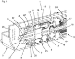
- Fig. 1 shows a sectional view through a drive 1, consisting of a geared motor 2 and a drive housing 5.
- the drive housing 5 has a motor mount 6, which is formed in the form of an intermediate wall and has an oval recess. From the drive housing 5 only a first half is shown here.
- the gear motor is composed of an electric motor 3 and a reduction gear 4.
- the electric motor is here a commutator with a grooved rotor core 17, a motor shaft 18, a bearing 19 (bearing plate not shown) and a motor housing 20.
- the motor housing 20 extends axially over the Engine out and serves as a transmission recording.
- the reduction gear 4 is embodied here in the form of a planetary gear, which has a sun gear 13, planet carrier 14, planetary gears 15, a first ring gear 16, a second ring gear 11, a damping means receiving 8 and an output shaft 21.
- the damping means receptacle 8 consists of a one-piece with the second ring gear 11 oval neck and is axially bounded by a radially inwardly extending end portion 12 of the ring gear 11 and a radial extension 10, whereby a positive engagement is given in the axial direction, which also as captive or Transport lock for the damping means 7 is used.
- the damping means 7 itself has on its outer contour a circumferential annular groove 22, with the aid of which the damping means 7 can be joined axially positively in the engine mount.
- a circuit board 26 and a stiffener 27 is shown.
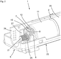
- Fig. 2 shows a partial spatial representation of the drive 1, with the gear motor 2, the drive housing 5, the motor mount 6, the Dämpfungsstoffability 8, the damping means 7, the motor housing 20, the output shaft 21, the circuit board 26, the stiffener 27, the extension 10th and the end portion 12 of the ring gear 11.
- a similarly constructed motor mount 6 is present. In principle, it is sufficient if one of the two motor mounts is equipped with an anti-twist device.
- Fig. 3 shows a sectional view through the drive 1, with the drive housing 5, the motor mount 6, which is formed on the one hand in a housing base 23 and on the other hand in a housing top 24, the damping means 7, the Dämpfungsstoffability 8, an output shaft 21, the output shaft bearing 25 and the circuit board 26th
- Fig. 4 shows a sectional view through the engine mount 6 a variant of the drive 1, with a geared motor 2, consisting of an electric motor 3 and a reduction gear 4, a drive housing 5, a motor mount 6, a damping means 7, a Dämpfungsstofffact 8, a motor axis of an extension 10, a first ring gear 16, a second ring gear 11, a sun gear 13, a planetary carrier 15, a planetary gear 14, a rotor laminated core 17, a motor shaft 18, a bearing 19, a motor housing, an output shaft 21, and an annular groove 22.
Landscapes
- Engineering & Computer Science (AREA)
- Structural Engineering (AREA)
- Architecture (AREA)
- Civil Engineering (AREA)
- Power Engineering (AREA)
- Connection Of Motors, Electrical Generators, Mechanical Devices, And The Like (AREA)
- Operating, Guiding And Securing Of Roll- Type Closing Members (AREA)
- Motor Or Generator Frames (AREA)
Abstract
Description
- Die Erfindung betrifft einen Antrieb (1), mit einem Getriebemotor (2), bestehend aus einem Elektromotor (3) und einem Untersetzungsgetriebe (4), einem Antriebsgehäuse (5), einer Motoraufnahme (6) für den Getriebemotor (2), einem zwischen der Motoraufnahme (6) und dem Getriebemotor (2) angeordneten Dämpfungsmittel (7) und einer Dämpfungsmittelaufnahme (8) für das Dämpfungsmittel (7) am Getriebemotor (2).
- Derartige Antriebe werden beispielhaft als Rollo- oder Jalousie-Antriebe eingesetzt, wobei das Antriebsgehäuse Teil einer Aufwickelvorrichtung ist. Die in solchen Antrieben eingesetzten Elektromotoren sind häufig mit genuteten Rotoren oder Statoren versehen, welche ein Rastmoment bewirken. Dieses dient im Stillstand als Bremsmoment. Im Betrieb werden hierdurch jedoch unerwünschte Vibrationen erzeugt. Um diese nicht oder nur geringfügig auf das Antriebsgehäuse, welches einen Resonanzkörper darstellt, zu übertragen, sind Dämpfungsmittel in Form von Gummi- oder gummiartigen Einlagen zwischen Getriebemotor und Antriebsgehäuse angeordnet. Dadurch ist kein direkter Kontakt zwischen Getriebemotor und Antriebsgehäuse vorhanden.
- Es sind bereits Antriebe bekannt, die Dämpfungsmittel zwischen einem Getriebemotor und einem Antriebsgehäuse aufweisen, wobei die Dämpfungsmittel beispielsweise auf einem ringförmigen Ansatz des Getriebemotors montiert und im Antriebsgehäuse in eine Gegenform aufgenommen sind. Hierbei sind zusätzliche Verdrehsicherungsgeometrien am Dämpfungsmittel, dem Getriebemotor und dem Antriebsgehäuse vorzusehen, welche verhindern, dass der Getriebemotor sich in Bezug auf das Antriebsgehäuse um seine eigene Achse verdrehen kann. Aus diesem Grund sind komplizierte Spritzgusswerkzeuge erforderlich, welche die Herstellung des Antriebs unwirtschaftlicher machen.
- Aufgabe der Erfindung ist es daher bei einem gattungsgemäßen Antrieb dafür zu sorgen, dass dieser auf einfache und wirtschaftliche Weise herstell- und montierbar ist, eine möglichst geringe Teileanzahl und eine zuverlässige Körperschallentkopplung aufweist.
- Diese Aufgabe wird erfindungsgemäß durch die Merkmale des Anspruchs 1 gelöst. Es ist vorgesehen, dass zwischen der Motoraufnahme und der Dämpfungsmittelaufnahme ein Formschluss besteht. Dieser Formschluss soll auch bestehen, wenn das Dämpfungsmittel nicht eingebaut ist. Das Dämpfungsmittel kann dennoch einfach und ohne Formschlusskonturen geformt sein und sich an die Formschlusskontur von Motoraufnahme und Dämpfungsmittelaufnahme anpassen.
- Weiterbildungen der Erfindung werden in den Unteransprüchen dargestellt. Der Formschluss ist in erster Linie in einer Rotationsrichtung um eine Motorachse ausgebildet, so dass der Getriebemotor gegen Verdrehen im Antriebsgehäuse gesichert ist.
- Weiter ist der Formschluss auch in radialer Richtung zu der Motorachse ausgebildet, damit der Getriebemotor sicher im Antriebsgehäuse gehalten ist.
- Zusätzlich ist der Formschluss auch in Motorachsrichtung ausgebildet, so dass der Getriebemotor damit in allen Freiheitsgraden formschlüssig im Antriebsgehäuse gehalten ist.
- Bei einer besonders vorteilhaften Weiterbildung der Erfindung ist vorgesehen, dass das Dämpfungsmittel eine elastische und dämpfende Verbindung zwischen der Motoraufnahme und der Dämpfungsmittelaufnahme herstellt. Durch die Elastizität des Dämpfungsmittels kann dieses sich an die Formschlusskonturen der Motoraufnahme und der Dämpfungsmittelaufnahme anpassen und dadurch insbesondere die auftretenden Kräfte in Rotationsrichtung vom Getriebemotor auf das Antriebsgehäuse übertragen, ohne für den eigentlichen Formschluss selbst zu sorgen oder einen solchen aufzuweisen.
- Es ist vorgesehen, dass das Dämpfungsmittel in seiner Grundform ringförmig ist, aber mit montierten Zustand nicht kreisförmig angeordnet ist. Dadurch ist eine besonders einfache Geometrie und damit eine besonders einfache Herstellbarkeit gegeben.
- Besonders vorteilhaft ist es, wenn der Querschnitt des Dämpfungsmittels über seinen Umfang gleich bleibt. Dadurch könnte der Dämpfungsring im Prinzip entlang seines Umfangs verschoben und verdreht werden, ohne die formschlüssige Wirkung zwischen dem Getriebemotor und der Motoraufnahme aufzuheben.
- Damit das Dämpfungselement axial formschlüssig in die Motoraufnahme gefügt werden kann, weist der Querschnitt des Dämpfungsmittels an seiner Außenkontur eine Ringnut auf.
- Zweckmäßigerweise ist das Dämpfungsmittel am Getriebemotor, insbesondere der Dämpfungsmittelaufnahme, sowohl in achsparalleler als auch in zur Motorachse radialer Richtung formschlüssig gehalten. Dadurch lässt sich das Dämpfungsmittel auf den Getriebemotor montieren und ist dadurch verliersicher vormontiert. Auf diese Weise kann der Getriebemotor und das Antriebsgehäuse an unterschiedlichen Orten hergestellt werden und später zur Herstellung des Antriebs zusammengeführt werden.
- Der Formschluss in achsparalleler Richtung besteht vorzugsweise aus einer radialen ringförmigen Erweiterung der Dämpfungsmittelaufnahme. Das elastische Dämpfungsmittel lässt sich leicht dehnen und über diese ringförmige Erweiterung in die Dämpfungsmittelaufnahme einfügen.
- Der Getriebemotor ist in seiner Grundform zylinderförmig und würde auf Grund seiner Außenkontur keinen Formschluss mit dem Antriebsgehäuse eingehen können. Deshalb ist vorgesehen, dass die Motoraufnahme im Antriebsgehäuse und die Dämpfungsmittelaufnahme des Getriebemotors elliptisch, oval oder dergleichen und jedenfalls nicht rotationssymmetrisch ausgebildet sind. Auf diese Weise ist eine Formschlusskontur gegeben. Zwischen der Motoraufnahme und der Dämpfungsmittelaufnahme ist ein Aufnahmeraum für das Dämpfungsmittel freigespart, der so bemessen ist, dass sich auch ohne das Dämpfungsmittel ein Formschluss bilden würde und das Dämpfungsmittel in der Hauptsache zur Dämpfung von Vibrationen des Getriebemotors dient. Das Dämpfungsmittel besitzt keine eigentliche Formschlusskontur, sondern übermittelt lediglich die Drehmomente, die im Betrieb auf das Gehäuse des Getriebemotors wirken über die unrunde Form der Dämpfungsmittelaufnahme auf die ähnlich geformte Motoraufnahme und damit auf das Antriebsgehäuse. Das Dämpfungsmittel wird dabei im Wesentlichen in radialer Richtung gestaucht und kaum in Umfangsrichtung belastet.
- Weiter ist vorgesehen das Antriebsgehäuse zweiteilig auszubilden, wobei eine erste Gehäusehälfte einen ersten Teil und eine zweite Gehäusehälfte einen zweiten Teil der Motoraufnahme aufweist. Innerhalb einer Gehäusehälfte ist die jeweilige Teil-Motoraufnahme etwa U-förmig geformt und die Montage des Getriebemotors ist dadurch besonders einfach, weil die Motoraufnahme wie eine Fügehilfe geformt ist.
- Bei Rollo-Antrieben werden besonders häufig Planetengetriebe als Untersetzungsgetriebe eingesetzt, weil diese eine zylindrische Außenkontur aufweisen, wie der Elektromotor. In einer Einheit als Getriebemotor lassen sie sich deshalb einfach in ein rohrförmiges Antriebsgehäuse integrieren oder einbauen. Hier wird vorgeschlagen, dass das Planetengetriebe ein Hohlrad aufweist, welches einstückig mit der Dämpfungsmittelaufnahme aus einem Kunststoffmaterial ausgebildet ist. Teileanzahl und der Montageaufwand lässt sich hierdurch reduzieren.
- Der oben genannte Formschluss des Dämpfungsmittels in der Dämpfungsmittelaufnahme wird in achsparalleler Richtung durch einen sich radial nach innen erstreckenden ringscheibenartigen Endbereich des Hohlrades gebildet.
- Ein Ausführungsbeispiel der Erfindung wird nachfolgend anhand der Zeichnung näher erläutert. Es zeigen:
- Fig. 1
- eine Schnittansicht durch den Antrieb,
- Fig. 2
- eine räumliche Teil-Darstellung des Antriebs
- Fig. 3
- eine Schnittdarstellung durch eine Motoraufnahme,
- Fig. 4
- eine Längs-Schnittdarstellung durch den Antrieb.
-
Fig. 1 zeigt eine Schnittansicht durch einen Antrieb 1, bestehend aus einem Getriebemotor 2 und einem Antriebsgehäuse 5. Das Antriebsgehäuse 5 weist eine Motoraufnahme 6 auf, welche in Form einer Zwischenwand ausgebildet ist und eine ovale Ausnehmung aufweist. Vom Antriebsgehäuse 5 ist hier nur eine erste Hälfte dargestellt. Der Getriebemotor ist zusammengesetzt aus einem Elektromotor 3 und einem Untersetzungsgetriebe 4. Der Elektromotor ist hier ein Kommutatormotor mit einem genuteten Rotorblechpaket 17, einer Motorwelle 18, einem Lager 19 (Lagerschild nicht dargestellt) und einem Motorgehäuse 20. Das Motorgehäuse 20 erstreckt sich axial über den Motor hinaus und dient dort als Getriebeaufnahme. Das Untersetzungsgetriebe 4 ist hier in Form eines Planetengetriebes ausgeführt, welches ein Sonnenrad 13, Planetenträger 14, Planetenräder 15, ein erstes Hohlrad 16, ein zweites Hohlrad 11, eine Dämpfungsmittelaufnahme 8 und eine Ausgangswelle 21 aufweist. Die Dämpfungsmittelaufnahme 8 besteht aus einem mit dem zweiten Hohlrad 11 einstückigen ovalen Ansatz und ist axial von einem sich radial nach innen erstreckenden Endbereich 12 des Hohlrades 11 und einer radialen Erweiterung 10 begrenzt, wodurch ein Formschluss in axialer Richtung gegeben ist, der auch als Verliersicherung oder Transportsicherung für das Dämpfungsmittel 7 dient. Das Dämpfungsmittel 7 selbst weist an seiner Außenkontur eine umlaufende Ringnut 22 auf, mit deren Hilfe das Dämpfungsmittel 7 axial formschlüssig in die Motoraufnahme gefügt werden kann. Weiter ist eine Leiterplatte 26 und eine Versteifung 27 dargestellt. -
Fig. 2 zeigt eine räumliche Teil-Darstellung des Antriebs 1, mit dem Getriebemotor 2, dem Antriebsgehäuse 5, der Motoraufnahme 6, der Dämpfungsmittelaufnahme 8, dem Dämpfungsmittel 7, dem Motorgehäuse 20, der Ausgangswelle 21, der Leiterplatte 26, der Versteifung 27, der Erweiterung 10 und dem Endbereich 12 des Hohlrades 11. An beiden Enden des Getriebemotors ist eine ähnlich aufgebaute Motoraufnahme 6 vorhanden. Prinzipiell genügt es, wenn eine der beiden Motoraufnahmen mit einer Verdrehsicherung ausgestattet ist. -
Fig. 3 zeigt eine Schnittdarstellung durch den Antrieb 1, mit dem Antriebsgehäuse 5, der Motoraufnahme 6, welche einerseits in einem Gehäuseunterteil 23 und andererseits in einem Gehäuseoberteil 24 ausgebildet ist, dem Dämpfungsmittel 7, der Dämpfungsmittelaufnahme 8, einer Ausgangswelle 21, dem Ausgangswellenlager 25 und der Leiterplatte 26. -
Fig. 4 zeigt eine Schnittdarstellung durch die Motoraufnahme 6 einer Variante des Antriebs 1, mit einem Getriebemotor 2, bestehend aus einem Elektromotor 3 und einem Untersetzungsgetriebe 4, einem Antriebsgehäuse 5, einer Motoraufnahme 6, einem Dämpfungsmittel 7, einer Dämpfungsmittelaufnahme 8, einer Motorachse einer Erweiterung 10, einem ersten Hohlrad 16, einem zweiten Hohlrad 11, einem Sonnenrad 13, einem Planetenträger 15, einem Planetenrad 14, einem Rotorblechpaket 17, einer Motorwelle 18, einem Lager 19, einem Motorgehäuse, einer Ausgangswelle 21 und einer Ringnut 22. -
- 1
- Antrieb
- 2
- Getriebemotor
- 3
- Elektromotor
- 4
- Untersetzungsgetriebe
- 5
- Antriebsgehäuse
- 6
- Motoraufnahme
- 7
- Dämpfungsmittel
- 8
- Dämpfungsmittelaufnahme
- 9
- Motorachse
- 10
- Erweiterung
- 11
- zweites Hohlrad
- 12
- Endbereich
- 13
- Sonnenrad
- 14
- Planetenrad
- 15
- Planetenträger
- 16
- erstes Hohlrad
- 17
- Rotorblechpaket
- 18
- Motorwelle
- 19
- Lager
- 20
- Motorgehäuse
- 21
- Ausgangswelle
- 22
- Ringnut
- 23
- Gehäuseunterteil
- 24
- Gehäuseoberteil
- 25
- Ausgangswellenlager
- 26
- Leiterplatte
- 27
- Versteifung
Claims (15)
- Antrieb (1), mit einem Getriebemotor (2), bestehend aus einem Elektromotor (3) und einem Untersetzungsgetriebe (4), einem Antriebsgehäuse (5), einer Motoraufnahme (6) für den Getriebemotor (2), einem zwischen der Motoraufnahme (6) und dem Getriebemotor (2) angeordneten Dämpfungsmittel (7) und einer Dämpfungsmittelaufnahme (8) für das Dämpfungsmittel (7) am Getriebemotor (2), dadurch gekennzeichnet, dass zwischen der Motoraufnahme (6) und der Dämpfungsmittelaufnahme (8) Formschluss besteht.
- Antrieb nach Anspruch 1, dadurch gekennzeichnet, dass der Formschluss in einer Rotationsrichtung um eine Motorachse (9) ausgebildet ist.
- Antrieb nach Anspruch 1 oder 2, dadurch gekennzeichnet, dass der Formschluss radial zu der Motorachse (9) ausgebildet ist.
- Antrieb nach Anspruch 1, 2 oder 3, dadurch gekennzeichnet, dass der Formschluss in Motorachsrichtung ausgebildet ist.
- Antrieb nach Anspruch 1, 2, 3 oder 4 dadurch gekennzeichnet, dass das Dämpfungsmittel (7) eine elastische und dämpfende Verbindung zwischen der Motoraufnahme (6) und der Dämpfungsmittelaufnahme (8) herstellt.
- Antrieb nach Anspruch 1, 2, 3, 4 oder 5, dadurch gekennzeichnet, dass das Dämpfungsmittel (7) in seiner Grundform ringförmig und im montierten Zustand nicht kreisförmig ist.
- Antrieb nach Anspruch 6, dadurch gekennzeichnet, dass der Querschnitt des Dämpfungsmittels (7) über seinen Umfang gleich bleibt.
- Antrieb nach Anspruch 6 oder 7, dadurch gekennzeichnet, dass der Querschnitt des Dämpfungsmittels (7) an seiner Außenkontur eine Ringnut (22) aufweist.
- Antrieb nach zumindest einem der vorangehenden Ansprüche, dadurch gekennzeichnet, dass das Dämpfungsmittel (7) am Getriebemotor (2), insbesondere der Dämpfungsmittelaufnahme (8), sowohl in achsparalleler als auch in zur Motorachse (9) radialer Richtung formschlüssig gehalten ist.
- Antrieb nach Anspruch 9, dadurch gekennzeichnet, dass der Formschluss in
achsparalleler Richtung aus einer radialen ringförmigen Erweiterung (10) der Dämpfungsmittelaufnahme (8) besteht. - Antrieb nach zumindest einem der vorangehenden Ansprüche, dadurch
gekennzeichnet, dass der Getriebemotor (2) in seiner Grundform zylinderförmig ist. - Antrieb nach zumindest einem der vorangehenden Ansprüche, dadurch
gekennzeichnet, dass die Motoraufnahme (6) und die Dämpfungsmittelaufnahme (8) elliptisch, oval oder dergleichen und nicht rotationssymmetrisch ausgebildet sind. - Antrieb nach zumindest einem der vorangehenden Ansprüche, dadurch
gekennzeichnet, dass das Antriebsgehäuse zweiteilig ausgebildet ist, wobei eine erste Gehäusehälfte einen ersten Teil und eine zweite Gehäusehälfte einen zweiten Teil der Motoraufnahme (6) aufweist. - Antrieb nach zumindest einem der vorangehenden Ansprüche, dadurch
gekennzeichnet, dass das Untersetzungsgetriebe (4) ein Planetengetriebe mit einem Hohlrad (11) aufweist, welches einstückig mit der Dämpfungsmittelaufnahme (8) aus einem Kunststoffmaterial ausgebildet ist. - Antrieb nach Anspruch 9, 10 und 14, dadurch gekennzeichnet, dass der
Formschluss in achsparalleler Richtung durch einen sich radial nach innen erstreckenden ringscheibenartigen Endbereich (12) des Hohlrades (11) gebildet ist.
Applications Claiming Priority (1)
| Application Number | Priority Date | Filing Date | Title |
|---|---|---|---|
| DE102017216646.0A DE102017216646A1 (de) | 2017-09-20 | 2017-09-20 | Antrieb |
Publications (2)
| Publication Number | Publication Date |
|---|---|
| EP3460962A1 true EP3460962A1 (de) | 2019-03-27 |
| EP3460962B1 EP3460962B1 (de) | 2020-11-04 |
Family
ID=63490303
Family Applications (1)
| Application Number | Title | Priority Date | Filing Date |
|---|---|---|---|
| EP18192210.5A Active EP3460962B1 (de) | 2017-09-20 | 2018-09-03 | Antrieb |
Country Status (4)
| Country | Link |
|---|---|
| US (1) | US10961775B2 (de) |
| EP (1) | EP3460962B1 (de) |
| DE (1) | DE102017216646A1 (de) |
| MX (1) | MX390326B (de) |
Families Citing this family (5)
| Publication number | Priority date | Publication date | Assignee | Title |
|---|---|---|---|---|
| EP3480415B1 (de) * | 2017-10-09 | 2024-08-28 | Hunter Douglas, Inc. | Kopfschienenanordnungen für architektonische abdeckungen und zugehörige verfahren |
| JP7374791B2 (ja) | 2020-01-31 | 2023-11-07 | マブチモーター株式会社 | 減速機およびギアドモータ |
| US20230203881A1 (en) * | 2020-06-03 | 2023-06-29 | Lutron Technology Company Llc | Motor shaft stabilizer |
| CN215255963U (zh) * | 2021-03-31 | 2021-12-21 | 宁波森瑞机电技术有限公司 | 一种用于电动窗帘的驱动装置及电动窗帘 |
| CN217285398U (zh) * | 2021-12-21 | 2022-08-26 | 宁波森瑞机电技术有限公司 | 一种窗帘驱动装置 |
Citations (5)
| Publication number | Priority date | Publication date | Assignee | Title |
|---|---|---|---|---|
| AT810U1 (de) * | 1994-10-13 | 1996-05-28 | Flender Austria Antriebstechni | Dämpfungselement zum befestigen von elektromotoren |
| US20110265958A1 (en) * | 2008-07-22 | 2011-11-03 | Hunter Douglas Inc. | Motor arrangement for window coverings |
| EP2642072A2 (de) * | 2012-03-20 | 2013-09-25 | Kabushiki Kaisha Toyota Jidoshokki | Motorbetriebener Verdichter |
| WO2014152427A1 (en) * | 2013-03-15 | 2014-09-25 | Springs Window Fashions, Llc | Window covering motorized lift and control system gear train |
| EP2922183A1 (de) * | 2014-03-20 | 2015-09-23 | Somfy SAS | Elektromechanisches Betätigungselement, zugeordnet Domotik-Installation und Herstellungsverfahren. |
Family Cites Families (3)
| Publication number | Priority date | Publication date | Assignee | Title |
|---|---|---|---|---|
| DE19613041A1 (de) * | 1996-04-01 | 1997-10-02 | Valeo Klimasysteme Gmbh | Gebläse einer Heizungs- und/oder Klimaanlage |
| US8307878B2 (en) * | 2009-01-14 | 2012-11-13 | Hunter Douglas Inc. | Noise dampening motor drive system for retractable covering for architectural openings |
| DE102011121177A1 (de) * | 2011-12-16 | 2013-06-20 | Oechsler Aktiengesellschaft | Motor eines elektromotorischen Stellelementes und Verfahren zu seiner Herstellung |
-
2017
- 2017-09-20 DE DE102017216646.0A patent/DE102017216646A1/de not_active Withdrawn
-
2018
- 2018-09-03 EP EP18192210.5A patent/EP3460962B1/de active Active
- 2018-09-13 US US16/130,296 patent/US10961775B2/en active Active
- 2018-09-14 MX MX2018011184A patent/MX390326B/es unknown
Patent Citations (5)
| Publication number | Priority date | Publication date | Assignee | Title |
|---|---|---|---|---|
| AT810U1 (de) * | 1994-10-13 | 1996-05-28 | Flender Austria Antriebstechni | Dämpfungselement zum befestigen von elektromotoren |
| US20110265958A1 (en) * | 2008-07-22 | 2011-11-03 | Hunter Douglas Inc. | Motor arrangement for window coverings |
| EP2642072A2 (de) * | 2012-03-20 | 2013-09-25 | Kabushiki Kaisha Toyota Jidoshokki | Motorbetriebener Verdichter |
| WO2014152427A1 (en) * | 2013-03-15 | 2014-09-25 | Springs Window Fashions, Llc | Window covering motorized lift and control system gear train |
| EP2922183A1 (de) * | 2014-03-20 | 2015-09-23 | Somfy SAS | Elektromechanisches Betätigungselement, zugeordnet Domotik-Installation und Herstellungsverfahren. |
Also Published As
| Publication number | Publication date |
|---|---|
| MX390326B (es) | 2025-03-20 |
| US20190085631A1 (en) | 2019-03-21 |
| DE102017216646A1 (de) | 2019-03-21 |
| EP3460962B1 (de) | 2020-11-04 |
| US10961775B2 (en) | 2021-03-30 |
| MX2018011184A (es) | 2019-03-21 |
Similar Documents
| Publication | Publication Date | Title |
|---|---|---|
| EP3460962A1 (de) | Antrieb | |
| EP1679223B1 (de) | Getriebe für eine Verstelleinrichtung | |
| DE102013114692B4 (de) | Wellgetriebe und hohler Rotationsaktuator | |
| DE102011113437B4 (de) | Kupplung und Motor | |
| DE102017122189A1 (de) | Hebevorrichtung für Fahrzeugheckklappe und Antriebsvorrichtung davon | |
| EP2730807B1 (de) | Planetengetriebe mit mehreren Getriebestufen | |
| DE3150572A1 (de) | Getriebemotor, insbesondere elektromotorischer fensterheber-antrieb | |
| EP2642159A1 (de) | Mehrstufiges Planetengetriebe | |
| DE3785931T2 (de) | Elastische kupplung. | |
| CH702879A2 (de) | Planetengetriebe in Wolfromanordnung sowie Elekromotor mit integriertem Planetengetriebe in Wolfromanordnung. | |
| DE102015202236A1 (de) | Zahnradanordnung | |
| DE4102932C2 (de) | Getriebemotor | |
| EP1968871B1 (de) | Trommelmotor | |
| DE102013112542A1 (de) | Getriebebaugruppe für eine elektromechanische Servolenkung | |
| DE19914555B4 (de) | Spannungswellengetriebe | |
| DE10149255B4 (de) | Wellgetriebe mit Planetenradantrieb | |
| EP0895001A2 (de) | Untersetzungsgetriebe | |
| DE202017100632U1 (de) | Antriebsanordnung für eine Fensterabschirmvorrichtung | |
| DE102015201158A1 (de) | Aktuatoreinheit | |
| DE102021205499A1 (de) | Antriebsvorrichtung und Statorbaugruppe hierfür | |
| DE102020111215A1 (de) | Rotorbaugruppe mit rotatorischer Sicherung zumindest eines Scheibenelementes; sowie elektrische Maschine | |
| DE202023100679U1 (de) | Übertragungssystem für Untersetzungsgetriebe | |
| DE102019117164A1 (de) | Getriebeanordnung für eine elektrisch antreibbare Achse eines Fahrzeugs | |
| DE29818204U1 (de) | Elektromotorischer Möbelantrieb | |
| DE102018205006A1 (de) | Zahnrad |
Legal Events
| Date | Code | Title | Description |
|---|---|---|---|
| PUAI | Public reference made under article 153(3) epc to a published international application that has entered the european phase |
Free format text: ORIGINAL CODE: 0009012 |
|
| STAA | Information on the status of an ep patent application or granted ep patent |
Free format text: STATUS: THE APPLICATION HAS BEEN PUBLISHED |
|
| AK | Designated contracting states |
Kind code of ref document: A1 Designated state(s): AL AT BE BG CH CY CZ DE DK EE ES FI FR GB GR HR HU IE IS IT LI LT LU LV MC MK MT NL NO PL PT RO RS SE SI SK SM TR |
|
| AX | Request for extension of the european patent |
Extension state: BA ME |
|
| STAA | Information on the status of an ep patent application or granted ep patent |
Free format text: STATUS: REQUEST FOR EXAMINATION WAS MADE |
|
| 17P | Request for examination filed |
Effective date: 20190328 |
|
| GRAP | Despatch of communication of intention to grant a patent |
Free format text: ORIGINAL CODE: EPIDOSNIGR1 |
|
| STAA | Information on the status of an ep patent application or granted ep patent |
Free format text: STATUS: GRANT OF PATENT IS INTENDED |
|
| RIC1 | Information provided on ipc code assigned before grant |
Ipc: H02K 5/24 20060101AFI20200415BHEP Ipc: E06B 9/322 20060101ALI20200415BHEP Ipc: E06B 9/72 20060101ALN20200415BHEP Ipc: E06B 9/70 20060101ALI20200415BHEP |
|
| INTG | Intention to grant announced |
Effective date: 20200508 |
|
| GRAS | Grant fee paid |
Free format text: ORIGINAL CODE: EPIDOSNIGR3 |
|
| GRAA | (expected) grant |
Free format text: ORIGINAL CODE: 0009210 |
|
| STAA | Information on the status of an ep patent application or granted ep patent |
Free format text: STATUS: THE PATENT HAS BEEN GRANTED |
|
| AK | Designated contracting states |
Kind code of ref document: B1 Designated state(s): AL AT BE BG CH CY CZ DE DK EE ES FI FR GB GR HR HU IE IS IT LI LT LU LV MC MK MT NL NO PL PT RO RS SE SI SK SM TR |
|
| REG | Reference to a national code |
Ref country code: GB Ref legal event code: FG4D Free format text: NOT ENGLISH |
|
| REG | Reference to a national code |
Ref country code: CH Ref legal event code: EP |
|
| REG | Reference to a national code |
Ref country code: AT Ref legal event code: REF Ref document number: 1332102 Country of ref document: AT Kind code of ref document: T Effective date: 20201115 |
|
| REG | Reference to a national code |
Ref country code: DE Ref legal event code: R096 Ref document number: 502018002898 Country of ref document: DE |
|
| REG | Reference to a national code |
Ref country code: IE Ref legal event code: FG4D Free format text: LANGUAGE OF EP DOCUMENT: GERMAN |
|
| REG | Reference to a national code |
Ref country code: NL Ref legal event code: MP Effective date: 20201104 |
|
| PG25 | Lapsed in a contracting state [announced via postgrant information from national office to epo] |
Ref country code: GR Free format text: LAPSE BECAUSE OF FAILURE TO SUBMIT A TRANSLATION OF THE DESCRIPTION OR TO PAY THE FEE WITHIN THE PRESCRIBED TIME-LIMIT Effective date: 20210205 Ref country code: NO Free format text: LAPSE BECAUSE OF FAILURE TO SUBMIT A TRANSLATION OF THE DESCRIPTION OR TO PAY THE FEE WITHIN THE PRESCRIBED TIME-LIMIT Effective date: 20210204 Ref country code: RS Free format text: LAPSE BECAUSE OF FAILURE TO SUBMIT A TRANSLATION OF THE DESCRIPTION OR TO PAY THE FEE WITHIN THE PRESCRIBED TIME-LIMIT Effective date: 20201104 Ref country code: PT Free format text: LAPSE BECAUSE OF FAILURE TO SUBMIT A TRANSLATION OF THE DESCRIPTION OR TO PAY THE FEE WITHIN THE PRESCRIBED TIME-LIMIT Effective date: 20210304 Ref country code: FI Free format text: LAPSE BECAUSE OF FAILURE TO SUBMIT A TRANSLATION OF THE DESCRIPTION OR TO PAY THE FEE WITHIN THE PRESCRIBED TIME-LIMIT Effective date: 20201104 |
|
| PG25 | Lapsed in a contracting state [announced via postgrant information from national office to epo] |
Ref country code: ES Free format text: LAPSE BECAUSE OF FAILURE TO SUBMIT A TRANSLATION OF THE DESCRIPTION OR TO PAY THE FEE WITHIN THE PRESCRIBED TIME-LIMIT Effective date: 20201104 Ref country code: BG Free format text: LAPSE BECAUSE OF FAILURE TO SUBMIT A TRANSLATION OF THE DESCRIPTION OR TO PAY THE FEE WITHIN THE PRESCRIBED TIME-LIMIT Effective date: 20210204 Ref country code: IS Free format text: LAPSE BECAUSE OF FAILURE TO SUBMIT A TRANSLATION OF THE DESCRIPTION OR TO PAY THE FEE WITHIN THE PRESCRIBED TIME-LIMIT Effective date: 20210304 Ref country code: LV Free format text: LAPSE BECAUSE OF FAILURE TO SUBMIT A TRANSLATION OF THE DESCRIPTION OR TO PAY THE FEE WITHIN THE PRESCRIBED TIME-LIMIT Effective date: 20201104 Ref country code: PL Free format text: LAPSE BECAUSE OF FAILURE TO SUBMIT A TRANSLATION OF THE DESCRIPTION OR TO PAY THE FEE WITHIN THE PRESCRIBED TIME-LIMIT Effective date: 20201104 Ref country code: SE Free format text: LAPSE BECAUSE OF FAILURE TO SUBMIT A TRANSLATION OF THE DESCRIPTION OR TO PAY THE FEE WITHIN THE PRESCRIBED TIME-LIMIT Effective date: 20201104 |
|
| REG | Reference to a national code |
Ref country code: LT Ref legal event code: MG9D |
|
| PG25 | Lapsed in a contracting state [announced via postgrant information from national office to epo] |
Ref country code: HR Free format text: LAPSE BECAUSE OF FAILURE TO SUBMIT A TRANSLATION OF THE DESCRIPTION OR TO PAY THE FEE WITHIN THE PRESCRIBED TIME-LIMIT Effective date: 20201104 |
|
| PG25 | Lapsed in a contracting state [announced via postgrant information from national office to epo] |
Ref country code: LT Free format text: LAPSE BECAUSE OF FAILURE TO SUBMIT A TRANSLATION OF THE DESCRIPTION OR TO PAY THE FEE WITHIN THE PRESCRIBED TIME-LIMIT Effective date: 20201104 Ref country code: SK Free format text: LAPSE BECAUSE OF FAILURE TO SUBMIT A TRANSLATION OF THE DESCRIPTION OR TO PAY THE FEE WITHIN THE PRESCRIBED TIME-LIMIT Effective date: 20201104 Ref country code: RO Free format text: LAPSE BECAUSE OF FAILURE TO SUBMIT A TRANSLATION OF THE DESCRIPTION OR TO PAY THE FEE WITHIN THE PRESCRIBED TIME-LIMIT Effective date: 20201104 Ref country code: EE Free format text: LAPSE BECAUSE OF FAILURE TO SUBMIT A TRANSLATION OF THE DESCRIPTION OR TO PAY THE FEE WITHIN THE PRESCRIBED TIME-LIMIT Effective date: 20201104 Ref country code: CZ Free format text: LAPSE BECAUSE OF FAILURE TO SUBMIT A TRANSLATION OF THE DESCRIPTION OR TO PAY THE FEE WITHIN THE PRESCRIBED TIME-LIMIT Effective date: 20201104 Ref country code: SM Free format text: LAPSE BECAUSE OF FAILURE TO SUBMIT A TRANSLATION OF THE DESCRIPTION OR TO PAY THE FEE WITHIN THE PRESCRIBED TIME-LIMIT Effective date: 20201104 |
|
| REG | Reference to a national code |
Ref country code: DE Ref legal event code: R097 Ref document number: 502018002898 Country of ref document: DE |
|
| PG25 | Lapsed in a contracting state [announced via postgrant information from national office to epo] |
Ref country code: DK Free format text: LAPSE BECAUSE OF FAILURE TO SUBMIT A TRANSLATION OF THE DESCRIPTION OR TO PAY THE FEE WITHIN THE PRESCRIBED TIME-LIMIT Effective date: 20201104 |
|
| PLBE | No opposition filed within time limit |
Free format text: ORIGINAL CODE: 0009261 |
|
| STAA | Information on the status of an ep patent application or granted ep patent |
Free format text: STATUS: NO OPPOSITION FILED WITHIN TIME LIMIT |
|
| 26N | No opposition filed |
Effective date: 20210805 |
|
| PG25 | Lapsed in a contracting state [announced via postgrant information from national office to epo] |
Ref country code: IT Free format text: LAPSE BECAUSE OF FAILURE TO SUBMIT A TRANSLATION OF THE DESCRIPTION OR TO PAY THE FEE WITHIN THE PRESCRIBED TIME-LIMIT Effective date: 20201104 Ref country code: NL Free format text: LAPSE BECAUSE OF FAILURE TO SUBMIT A TRANSLATION OF THE DESCRIPTION OR TO PAY THE FEE WITHIN THE PRESCRIBED TIME-LIMIT Effective date: 20201104 Ref country code: AL Free format text: LAPSE BECAUSE OF FAILURE TO SUBMIT A TRANSLATION OF THE DESCRIPTION OR TO PAY THE FEE WITHIN THE PRESCRIBED TIME-LIMIT Effective date: 20201104 |
|
| PG25 | Lapsed in a contracting state [announced via postgrant information from national office to epo] |
Ref country code: SI Free format text: LAPSE BECAUSE OF FAILURE TO SUBMIT A TRANSLATION OF THE DESCRIPTION OR TO PAY THE FEE WITHIN THE PRESCRIBED TIME-LIMIT Effective date: 20201104 |
|
| REG | Reference to a national code |
Ref country code: CH Ref legal event code: PL |
|
| REG | Reference to a national code |
Ref country code: BE Ref legal event code: MM Effective date: 20210930 |
|
| PG25 | Lapsed in a contracting state [announced via postgrant information from national office to epo] |
Ref country code: IS Free format text: LAPSE BECAUSE OF FAILURE TO SUBMIT A TRANSLATION OF THE DESCRIPTION OR TO PAY THE FEE WITHIN THE PRESCRIBED TIME-LIMIT Effective date: 20210304 Ref country code: MC Free format text: LAPSE BECAUSE OF FAILURE TO SUBMIT A TRANSLATION OF THE DESCRIPTION OR TO PAY THE FEE WITHIN THE PRESCRIBED TIME-LIMIT Effective date: 20201104 |
|
| PG25 | Lapsed in a contracting state [announced via postgrant information from national office to epo] |
Ref country code: LU Free format text: LAPSE BECAUSE OF NON-PAYMENT OF DUE FEES Effective date: 20210903 Ref country code: IE Free format text: LAPSE BECAUSE OF NON-PAYMENT OF DUE FEES Effective date: 20210903 Ref country code: FR Free format text: LAPSE BECAUSE OF NON-PAYMENT OF DUE FEES Effective date: 20210930 Ref country code: BE Free format text: LAPSE BECAUSE OF NON-PAYMENT OF DUE FEES Effective date: 20210930 |
|
| PG25 | Lapsed in a contracting state [announced via postgrant information from national office to epo] |
Ref country code: LI Free format text: LAPSE BECAUSE OF NON-PAYMENT OF DUE FEES Effective date: 20210930 Ref country code: CH Free format text: LAPSE BECAUSE OF NON-PAYMENT OF DUE FEES Effective date: 20210930 |
|
| GBPC | Gb: european patent ceased through non-payment of renewal fee |
Effective date: 20220903 |
|
| PG25 | Lapsed in a contracting state [announced via postgrant information from national office to epo] |
Ref country code: CY Free format text: LAPSE BECAUSE OF FAILURE TO SUBMIT A TRANSLATION OF THE DESCRIPTION OR TO PAY THE FEE WITHIN THE PRESCRIBED TIME-LIMIT Effective date: 20201104 |
|
| PG25 | Lapsed in a contracting state [announced via postgrant information from national office to epo] |
Ref country code: HU Free format text: LAPSE BECAUSE OF FAILURE TO SUBMIT A TRANSLATION OF THE DESCRIPTION OR TO PAY THE FEE WITHIN THE PRESCRIBED TIME-LIMIT; INVALID AB INITIO Effective date: 20180903 |
|
| P01 | Opt-out of the competence of the unified patent court (upc) registered |
Effective date: 20230920 |
|
| PG25 | Lapsed in a contracting state [announced via postgrant information from national office to epo] |
Ref country code: GB Free format text: LAPSE BECAUSE OF NON-PAYMENT OF DUE FEES Effective date: 20220903 |
|
| PG25 | Lapsed in a contracting state [announced via postgrant information from national office to epo] |
Ref country code: MK Free format text: LAPSE BECAUSE OF FAILURE TO SUBMIT A TRANSLATION OF THE DESCRIPTION OR TO PAY THE FEE WITHIN THE PRESCRIBED TIME-LIMIT Effective date: 20201104 |
|
| PG25 | Lapsed in a contracting state [announced via postgrant information from national office to epo] |
Ref country code: MT Free format text: LAPSE BECAUSE OF FAILURE TO SUBMIT A TRANSLATION OF THE DESCRIPTION OR TO PAY THE FEE WITHIN THE PRESCRIBED TIME-LIMIT Effective date: 20201104 |
|
| REG | Reference to a national code |
Ref country code: AT Ref legal event code: MM01 Ref document number: 1332102 Country of ref document: AT Kind code of ref document: T Effective date: 20230903 |
|
| PG25 | Lapsed in a contracting state [announced via postgrant information from national office to epo] |
Ref country code: AT Free format text: LAPSE BECAUSE OF NON-PAYMENT OF DUE FEES Effective date: 20230903 |
|
| PG25 | Lapsed in a contracting state [announced via postgrant information from national office to epo] |
Ref country code: AT Free format text: LAPSE BECAUSE OF NON-PAYMENT OF DUE FEES Effective date: 20230903 |
|
| REG | Reference to a national code |
Ref country code: DE Ref legal event code: R084 Ref document number: 502018002898 Country of ref document: DE |
|
| PGFP | Annual fee paid to national office [announced via postgrant information from national office to epo] |
Ref country code: DE Payment date: 20250905 Year of fee payment: 8 |
|
| PG25 | Lapsed in a contracting state [announced via postgrant information from national office to epo] |
Ref country code: TR Free format text: LAPSE BECAUSE OF FAILURE TO SUBMIT A TRANSLATION OF THE DESCRIPTION OR TO PAY THE FEE WITHIN THE PRESCRIBED TIME-LIMIT Effective date: 20201104 |
|
| PGFP | Annual fee paid to national office [announced via postgrant information from national office to epo] |
Ref country code: AT Payment date: 20260410 Year of fee payment: 5 |