EP3460984A1 - Dispositif de surveillance pour une machine à réluctance, machine à réluctance et procédé de surveillance - Google Patents
Dispositif de surveillance pour une machine à réluctance, machine à réluctance et procédé de surveillance Download PDFInfo
- Publication number
- EP3460984A1 EP3460984A1 EP17192677.7A EP17192677A EP3460984A1 EP 3460984 A1 EP3460984 A1 EP 3460984A1 EP 17192677 A EP17192677 A EP 17192677A EP 3460984 A1 EP3460984 A1 EP 3460984A1
- Authority
- EP
- European Patent Office
- Prior art keywords
- reluctance machine
- vector
- monitoring device
- monitoring
- component
- Prior art date
- Legal status (The legal status is an assumption and is not a legal conclusion. Google has not performed a legal analysis and makes no representation as to the accuracy of the status listed.)
- Withdrawn
Links
- 238000012806 monitoring device Methods 0.000 title claims abstract description 16
- 238000000034 method Methods 0.000 title claims description 15
- 238000012544 monitoring process Methods 0.000 title claims description 11
- 239000013598 vector Substances 0.000 claims abstract description 42
- 238000011156 evaluation Methods 0.000 claims abstract description 7
- 230000000903 blocking effect Effects 0.000 description 8
- 238000010586 diagram Methods 0.000 description 8
- 238000005259 measurement Methods 0.000 description 5
- 230000004907 flux Effects 0.000 description 4
- 238000005070 sampling Methods 0.000 description 3
- 230000009466 transformation Effects 0.000 description 3
- 244000145845 chattering Species 0.000 description 2
- 230000001276 controlling effect Effects 0.000 description 2
- 230000010354 integration Effects 0.000 description 2
- 238000012545 processing Methods 0.000 description 2
- 230000001360 synchronised effect Effects 0.000 description 2
- 101100008044 Caenorhabditis elegans cut-1 gene Proteins 0.000 description 1
- 230000001133 acceleration Effects 0.000 description 1
- 230000015572 biosynthetic process Effects 0.000 description 1
- 238000001514 detection method Methods 0.000 description 1
- 239000002184 metal Substances 0.000 description 1
- 230000001105 regulatory effect Effects 0.000 description 1
- 230000001131 transforming effect Effects 0.000 description 1
- 238000004804 winding Methods 0.000 description 1
Images

Classifications
-
- H—ELECTRICITY
- H02—GENERATION; CONVERSION OR DISTRIBUTION OF ELECTRIC POWER
- H02P—CONTROL OR REGULATION OF ELECTRIC MOTORS, ELECTRIC GENERATORS OR DYNAMO-ELECTRIC CONVERTERS; CONTROLLING TRANSFORMERS, REACTORS OR CHOKE COILS
- H02P21/00—Arrangements or methods for the control of electric machines by vector control, e.g. by control of field orientation
- H02P21/05—Arrangements or methods for the control of electric machines by vector control, e.g. by control of field orientation specially adapted for damping motor oscillations, e.g. for reducing hunting
-
- H—ELECTRICITY
- H02—GENERATION; CONVERSION OR DISTRIBUTION OF ELECTRIC POWER
- H02P—CONTROL OR REGULATION OF ELECTRIC MOTORS, ELECTRIC GENERATORS OR DYNAMO-ELECTRIC CONVERTERS; CONTROLLING TRANSFORMERS, REACTORS OR CHOKE COILS
- H02P21/00—Arrangements or methods for the control of electric machines by vector control, e.g. by control of field orientation
- H02P21/04—Arrangements or methods for the control of electric machines by vector control, e.g. by control of field orientation specially adapted for very low speeds
-
- H—ELECTRICITY
- H02—GENERATION; CONVERSION OR DISTRIBUTION OF ELECTRIC POWER
- H02P—CONTROL OR REGULATION OF ELECTRIC MOTORS, ELECTRIC GENERATORS OR DYNAMO-ELECTRIC CONVERTERS; CONTROLLING TRANSFORMERS, REACTORS OR CHOKE COILS
- H02P21/00—Arrangements or methods for the control of electric machines by vector control, e.g. by control of field orientation
- H02P21/13—Observer control, e.g. using Luenberger observers or Kalman filters
-
- H—ELECTRICITY
- H02—GENERATION; CONVERSION OR DISTRIBUTION OF ELECTRIC POWER
- H02P—CONTROL OR REGULATION OF ELECTRIC MOTORS, ELECTRIC GENERATORS OR DYNAMO-ELECTRIC CONVERTERS; CONTROLLING TRANSFORMERS, REACTORS OR CHOKE COILS
- H02P21/00—Arrangements or methods for the control of electric machines by vector control, e.g. by control of field orientation
- H02P21/14—Estimation or adaptation of machine parameters, e.g. flux, current or voltage
-
- H—ELECTRICITY
- H02—GENERATION; CONVERSION OR DISTRIBUTION OF ELECTRIC POWER
- H02P—CONTROL OR REGULATION OF ELECTRIC MOTORS, ELECTRIC GENERATORS OR DYNAMO-ELECTRIC CONVERTERS; CONTROLLING TRANSFORMERS, REACTORS OR CHOKE COILS
- H02P21/00—Arrangements or methods for the control of electric machines by vector control, e.g. by control of field orientation
- H02P21/14—Estimation or adaptation of machine parameters, e.g. flux, current or voltage
- H02P21/141—Flux estimation
-
- H—ELECTRICITY
- H02—GENERATION; CONVERSION OR DISTRIBUTION OF ELECTRIC POWER
- H02P—CONTROL OR REGULATION OF ELECTRIC MOTORS, ELECTRIC GENERATORS OR DYNAMO-ELECTRIC CONVERTERS; CONTROLLING TRANSFORMERS, REACTORS OR CHOKE COILS
- H02P21/00—Arrangements or methods for the control of electric machines by vector control, e.g. by control of field orientation
- H02P21/14—Estimation or adaptation of machine parameters, e.g. flux, current or voltage
- H02P21/18—Estimation of position or speed
-
- H—ELECTRICITY
- H02—GENERATION; CONVERSION OR DISTRIBUTION OF ELECTRIC POWER
- H02P—CONTROL OR REGULATION OF ELECTRIC MOTORS, ELECTRIC GENERATORS OR DYNAMO-ELECTRIC CONVERTERS; CONTROLLING TRANSFORMERS, REACTORS OR CHOKE COILS
- H02P21/00—Arrangements or methods for the control of electric machines by vector control, e.g. by control of field orientation
- H02P21/34—Arrangements for starting
-
- H—ELECTRICITY
- H02—GENERATION; CONVERSION OR DISTRIBUTION OF ELECTRIC POWER
- H02P—CONTROL OR REGULATION OF ELECTRIC MOTORS, ELECTRIC GENERATORS OR DYNAMO-ELECTRIC CONVERTERS; CONTROLLING TRANSFORMERS, REACTORS OR CHOKE COILS
- H02P25/00—Arrangements or methods for the control of AC motors characterised by the kind of AC motor or by structural details
- H02P25/02—Arrangements or methods for the control of AC motors characterised by the kind of AC motor or by structural details characterised by the kind of motor
- H02P25/08—Reluctance motors
- H02P25/086—Commutation
- H02P25/089—Sensorless control
Definitions
- the invention relates to a reluctance machine and its monitoring.
- a synchronous reluctance machine can be controlled or regulated.
- Reluctance machines are available as a reluctance motor or as a reluctance generator. To determine the position of the rotor (also called rotor) of the reluctance machine, a sensor can be used. The reluctance machine can also be operated without encoder.
- a field-oriented control can be used.
- EP 2 023 479 B1 From the EP 2 023 479 B1 is a system for seamless speed and / or position detection including standstill in a permanent magnet rotor of an electric machine known. A method for determining an electrical drive speed and / or attitude from a measurement of a multi-phase stator current is described.
- a plausibility monitoring system for motion measurements on an electric drive device is known.
- the motion measurement of a sensor is monitored.
- one or more estimated values are obtained is generated for the position, speed and / or acceleration of the drive device, wherein the one or more estimated values are compared in correspondence with one or more measured values generated from the encoder output signals.
- a reluctance machine in particular a synchronous reluctance machine, can be used in a sensorless operation.
- the encoderless operation the reluctance machine can be operated controlled.
- controlled operation a parameterized current is impressed.
- controlled operation in particular a range of low output frequencies is passed through. The current is adjusted in particular so that an expected moment can be applied or generated. If the amplitude of the current is too small, the rotor is not accelerated as desired and the reluctance motor tilts or blocks.
- the current pointer rotates over the rotor and alternately generates a positive and a negative moment when passing over the torque axis. This is perceived as "rattling".
- the speed remains zero on average; the rotor of the reluctance machine, or a shaft which is connected to the rotor, so blocked.
- An object of the invention is to safely operate a reluctance machine.
- a solution to the problem results in a monitoring device for a reluctance machine according to claim 1 or in a method for monitoring a reluctance machine according to claim 5.
- Respective embodiments result according to claims 1 to 4 or 6 to 9.
- the current regulator of the reluctance machine can well compensate the resulting harmonics (in particular the 2-fold stator frequency) at low frequencies. Therefore, the monitoring can be improved.
- the difference between the nominal and actual flow can be monitored and the rotor monitored. Also, by using a sensor, the blocking (rattling) of the rotor, or the blocking of a shaft connected to the rotor can be detected.
- the fundamental frequency is the frequency of the current vector.
- the frequency of the flow is with the number of pole pairs on the St Sseite transformed.
- the current controller To regulate the desired current vector, the current controller generates a voltage vector which generates a component with a negative-rotating fundamental frequency.
- the space pointer By transforming the space pointer into a coordinate system that rotates at a negative fundamental frequency, all frequency components are shifted by the fundamental frequency.
- the resulting from the complex complexed current component thus becomes a DC component.
- This DC component can be filtered out of the signal with a low-pass filter and used to detect the blocked wave. This results in a further possibility of monitoring the reluctance machine.
- a reluctance machine monitor includes a vector rotator for rotating a space vector, a low pass filter for the rotated space vector, and a signal evaluation for the output of the low pass filter.
- a standing (rattling) shaft or rotor can be detected.
- the vector rotator is designed to rotate the space vector by a negative fundamental frequency. So it can be determined if there is a DC component.
- the space vector is a voltage vector.
- the voltage vector corresponds to the flow pointer.
- the space pointer can alternatively also be the flow pointer.
- the signal evaluation has an absolute value generator and a threshold value comparator.
- the low pass can be used to determine a DC component. From this DC component of the space vector, which relates to the flow or the voltage, the amount is formed. The amount can then be compared to a threshold. If the amount above the threshold becomes one Error found. Thus, a blocking (rattling) of the shaft (the rotor) is detected.
- the blocking (rattling) of the shaft can be detected in the whole speed range as opposed to monitoring the variance of the current.
- an operator of the reluctance machine can be made aware of faulty parameterization more quickly (for example, too low a starting current for the controlled operation).
- a room pointer for the flow or for a voltage is monitored.
- the space vector is transformed by a fundamental frequency.
- the transformation takes place in particular around the negative fundamental frequency.
- the fundamental frequency corresponds in particular to the predetermined rotational speed of the reluctance machine.
- the DC component of the transformed space vector is monitored. In regular operation, this DC component is zero or almost zero. The DC component increases when the rotor locks or rattles.
- the DC component which may be present is generated or determined by means of a low-pass filter.
- the DC component is compared with a threshold value and an error message is issued when the DC component of the vector-transformed spatial vector reaches and / or exceeds the threshold value.
- hysteresis can also be used in one embodiment.
- the reluctance machine is operated with the monitoring as an encoderless reluctance machine.
- reliable operation of the reluctance machine can be achieved inexpensively without encoder.
- the reluctance machine is operated in a controlled mode.
- the start of the reluctance machine can be performed safely.
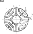
- FIG. 1 shows a rotor sheet section 1 of a reluctance machine. Shown further is a pole 2 and a pole gap 3 together with the axes d and q of the flux based on the Park transformation.
- the d-axis relates to the flow-forming portion and the q-axis relates to the moment-forming portion of the total flow.
- the rotor sheet cut 1 is a typical example of a rotor of a reluctance type machine.
- the flow ⁇ d and the flow ⁇ q are also shown.
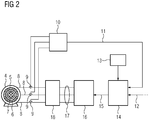
- FIG. 2 shows a reluctance machine 4 with a current controller 14.
- the reluctance machine 4 has a stator 5 with stator 6, in which stator windings are inserted. Shown is also a rotor 7, the sheet metal section is indicated.
- the reluctance machine 4 has a three-phase power connection 8. For measuring a current or a voltage for the phases of the power connection 8, a three-phase transducer 9 is provided. The recorded measured values are displayed in an actual value processing 10 processed. The actual value processing 10 results in an actual current value I.
- This current actual value I is an input value of the current regulator 14.
- Another input value of the current regulator 14 is the current setpoint I soll 12.
- the current regulator 14 has a link to a motor model 13.
- An output value of the current controller 14 is the voltage setpoint U 15.
- the voltage setpoint U 15 is an input variable of an inverter controller 16.
- the inverter controller 16 has as output variables control signals 17, which are supplied to an inverter 18.
- the inverter 18 serves to feed the reluctance machine 14 with electrical energy.
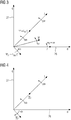
- FIG. 3 shows a phasor diagram for the reluctance machine, wherein in the phasor diagram, the voltage vectors are not shown separately.
- the voltage vector results from the time derivative of the flow and is rotated by 90 ° to the flow pointer.
- the phasor diagram is based on the representation of the d-axis 26 and the q-axis 27. Shown are the current vector I , the flow ⁇ I , the flow ⁇ and the flow ⁇ I *.
- the space vectors move, as shown, with the electrical rotor angular velocity ⁇ r .
- FIG. 3 shows the phasor diagram of the reluctance machine in normal operation.
- the representation after FIG. 4 shows a further vector diagram with the axes d 26 and q 27. Also shown is the current vector I with the angular velocity ⁇ and the pointer ⁇ I running on this and the order by - ⁇ shifted pointer ⁇ I *.
- FIG. 4 shows the representation FIG. 4 not a normal operating condition but the fault case, in which the shaft or the rotor is blocked, so rattles.
- the flow pointer ⁇ I rotates at the angular velocity ⁇ .
- the pointer ⁇ I * rotates at the angular velocity - ⁇ .
- the pointers ⁇ I and ⁇ I * rotate in opposite directions. This results in a DC component, which can be detected.
- the representation after FIG. 5 shows a monitoring device 19.
- the monitoring device 19 is used to monitor the reluctance machine.
- the monitoring device has input signals 21 and 25.
- the input signal 21 is a space vector, in particular a stator-fixed voltage vector U ab (terminal voltage of the motor).
- the input signal 25 is a negative angular frequency 2 ⁇ (-f Fund ).
- the fundamental frequency f Fund is negated by the negative sign.
- the negative angular frequency 25 is sampled by means of a sampling with the sampling frequency T ab .
- For a vector rotator 20 takes place by means of an angular integration 24, an integration of the input signal 25 over the sampling time.
- the output of the angle integrator 24 is fed to the vector rotator 20 which rotates the space vector 21.
- the space vector 21 rotated at the negative angular frequency is passed through a low-pass filter 22.
- the output signal of the low-pass filter 22 is further processed in a signal evaluation 23.
- the signal evaluation 23 is for example an absolute value generator, wherein in the present case an absolute value formation of the components of the voltage vector
- an absolute value generator
Landscapes
- Engineering & Computer Science (AREA)
- Power Engineering (AREA)
- Control Of Electric Motors In General (AREA)
- Control Of Motors That Do Not Use Commutators (AREA)
- Combined Controls Of Internal Combustion Engines (AREA)
Priority Applications (6)
| Application Number | Priority Date | Filing Date | Title |
|---|---|---|---|
| EP17192677.7A EP3460984A1 (fr) | 2017-09-22 | 2017-09-22 | Dispositif de surveillance pour une machine à réluctance, machine à réluctance et procédé de surveillance |
| PCT/EP2018/074708 WO2019057596A1 (fr) | 2017-09-22 | 2018-09-13 | Dispositif de surveillance pour une machine à reluctance et procédé de surveillance |
| EP18779230.4A EP3656049B1 (fr) | 2017-09-22 | 2018-09-13 | Dispositif de surveillance pour une machine à réluctance, machine à réluctance et procédé de surveillance |
| RU2020110802A RU2755671C1 (ru) | 2017-09-22 | 2018-09-13 | Мониторинговое устройство для реактивной машины и способ мониторинга |
| CN201880061500.2A CN111149290B (zh) | 2017-09-22 | 2018-09-13 | 用于磁阻电机的监控装置和监控方法 |
| US16/649,529 US11201575B2 (en) | 2017-09-22 | 2018-09-13 | Monitoring device for a reluctance machine and method for monitoring |
Applications Claiming Priority (1)
| Application Number | Priority Date | Filing Date | Title |
|---|---|---|---|
| EP17192677.7A EP3460984A1 (fr) | 2017-09-22 | 2017-09-22 | Dispositif de surveillance pour une machine à réluctance, machine à réluctance et procédé de surveillance |
Publications (1)
| Publication Number | Publication Date |
|---|---|
| EP3460984A1 true EP3460984A1 (fr) | 2019-03-27 |
Family
ID=59955453
Family Applications (2)
| Application Number | Title | Priority Date | Filing Date |
|---|---|---|---|
| EP17192677.7A Withdrawn EP3460984A1 (fr) | 2017-09-22 | 2017-09-22 | Dispositif de surveillance pour une machine à réluctance, machine à réluctance et procédé de surveillance |
| EP18779230.4A Active EP3656049B1 (fr) | 2017-09-22 | 2018-09-13 | Dispositif de surveillance pour une machine à réluctance, machine à réluctance et procédé de surveillance |
Family Applications After (1)
| Application Number | Title | Priority Date | Filing Date |
|---|---|---|---|
| EP18779230.4A Active EP3656049B1 (fr) | 2017-09-22 | 2018-09-13 | Dispositif de surveillance pour une machine à réluctance, machine à réluctance et procédé de surveillance |
Country Status (5)
| Country | Link |
|---|---|
| US (1) | US11201575B2 (fr) |
| EP (2) | EP3460984A1 (fr) |
| CN (1) | CN111149290B (fr) |
| RU (1) | RU2755671C1 (fr) |
| WO (1) | WO2019057596A1 (fr) |
Citations (7)
| Publication number | Priority date | Publication date | Assignee | Title |
|---|---|---|---|---|
| DE19703248A1 (de) | 1997-01-29 | 1998-08-13 | Siemens Ag | Verfahren und Vorrichtung zur Bestimmung einer Drehzahl einer geberlosen, feldorientiert betriebenen Drehfeldmaschine |
| DE102006008497A1 (de) * | 2005-02-25 | 2006-08-31 | International Rectifier Corp., El Segundo | Schaltung und Verfahren zur Erkennung einer Synchronmotor-Anlassblockierung |
| US20070001635A1 (en) * | 2005-07-01 | 2007-01-04 | International Rectifier Corporation | Method and system for starting a sensorless motor |
| EP2226929A1 (fr) | 2009-03-06 | 2010-09-08 | Baumüller Nürnberg GmbH | Système de surveillance de la plausibilité pour des mesures de mouvements sur un dispositif d'entraînement électrique |
| EP2023479B1 (fr) | 2007-08-06 | 2014-04-16 | Baumüller Nürnberg Gmbh | Dispositif destiné au calcul de la vitesse et/ou de l'emplacement sans fil incluant un arrêt pour un rotor magnétique permanent de machine électrique |
| DE102013212876A1 (de) * | 2013-07-02 | 2015-01-08 | Robert Bosch Gmbh | Verfahren und Vorrichtung zur sensorlosen Ermittlungeiner Läuferlage einer elektrischen Maschine |
| US20170237376A1 (en) * | 2016-02-12 | 2017-08-17 | Kabushiki Kaisha Yaskawa Denki | Motor controller and method for controlling motor |
Family Cites Families (10)
| Publication number | Priority date | Publication date | Assignee | Title |
|---|---|---|---|---|
| CN100461611C (zh) * | 2005-07-01 | 2009-02-11 | 国际整流器公司 | 启动无传感器马达的系统和方法 |
| GB0526276D0 (en) * | 2005-12-23 | 2006-02-01 | Trw Ltd | Electric motor control |
| CN102160269B (zh) | 2008-09-22 | 2015-11-25 | 西门子工业公司 | 用于管理无功功率的系统、设备和方法 |
| CN101777862B (zh) * | 2010-01-18 | 2011-11-30 | 南京信息职业技术学院 | 无轴承同步磁阻电机的位移估算方法、无位移传感器控制方法和装置 |
| US8963459B2 (en) * | 2011-09-07 | 2015-02-24 | Samsung Techwin Co., Ltd. | Method and apparatus for driving alternating-current motor |
| CN202696533U (zh) * | 2012-06-18 | 2013-01-23 | 浙江大学 | 一种变速永磁交流发电机系统 |
| CN102832860B (zh) * | 2012-09-07 | 2015-07-08 | 浙江大学 | 一种基于同步驱动的双开关磁阻电机系统 |
| WO2014091703A1 (fr) * | 2012-12-10 | 2014-06-19 | パナソニック株式会社 | Dispositif d'entraînement de tambour, et lave-linge et sèche-linge l'utilisant |
| WO2016121237A1 (fr) * | 2015-01-28 | 2016-08-04 | 株式会社 東芝 | Dispositif de commande d'onduleur et système d'attaque de moteur |
| US9948224B1 (en) * | 2016-10-17 | 2018-04-17 | General Electric Company | System and method for sensorless control of electric machines using magnetic alignment signatures |
-
2017
- 2017-09-22 EP EP17192677.7A patent/EP3460984A1/fr not_active Withdrawn
-
2018
- 2018-09-13 EP EP18779230.4A patent/EP3656049B1/fr active Active
- 2018-09-13 WO PCT/EP2018/074708 patent/WO2019057596A1/fr not_active Ceased
- 2018-09-13 RU RU2020110802A patent/RU2755671C1/ru active
- 2018-09-13 US US16/649,529 patent/US11201575B2/en active Active
- 2018-09-13 CN CN201880061500.2A patent/CN111149290B/zh active Active
Patent Citations (7)
| Publication number | Priority date | Publication date | Assignee | Title |
|---|---|---|---|---|
| DE19703248A1 (de) | 1997-01-29 | 1998-08-13 | Siemens Ag | Verfahren und Vorrichtung zur Bestimmung einer Drehzahl einer geberlosen, feldorientiert betriebenen Drehfeldmaschine |
| DE102006008497A1 (de) * | 2005-02-25 | 2006-08-31 | International Rectifier Corp., El Segundo | Schaltung und Verfahren zur Erkennung einer Synchronmotor-Anlassblockierung |
| US20070001635A1 (en) * | 2005-07-01 | 2007-01-04 | International Rectifier Corporation | Method and system for starting a sensorless motor |
| EP2023479B1 (fr) | 2007-08-06 | 2014-04-16 | Baumüller Nürnberg Gmbh | Dispositif destiné au calcul de la vitesse et/ou de l'emplacement sans fil incluant un arrêt pour un rotor magnétique permanent de machine électrique |
| EP2226929A1 (fr) | 2009-03-06 | 2010-09-08 | Baumüller Nürnberg GmbH | Système de surveillance de la plausibilité pour des mesures de mouvements sur un dispositif d'entraînement électrique |
| DE102013212876A1 (de) * | 2013-07-02 | 2015-01-08 | Robert Bosch Gmbh | Verfahren und Vorrichtung zur sensorlosen Ermittlungeiner Läuferlage einer elektrischen Maschine |
| US20170237376A1 (en) * | 2016-02-12 | 2017-08-17 | Kabushiki Kaisha Yaskawa Denki | Motor controller and method for controlling motor |
Also Published As
| Publication number | Publication date |
|---|---|
| CN111149290B (zh) | 2023-08-22 |
| EP3656049C0 (fr) | 2024-02-28 |
| EP3656049A1 (fr) | 2020-05-27 |
| EP3656049B1 (fr) | 2024-02-28 |
| RU2755671C1 (ru) | 2021-09-20 |
| US11201575B2 (en) | 2021-12-14 |
| WO2019057596A1 (fr) | 2019-03-28 |
| US20200259441A1 (en) | 2020-08-13 |
| CN111149290A (zh) | 2020-05-12 |
Similar Documents
| Publication | Publication Date | Title |
|---|---|---|
| EP2421148B1 (fr) | Dispositif et procédé d'identification des paramètres de référence mécaniques d'un moteur asynchrone triphasé sans utilisation d'encodeur de vitesse | |
| EP2499737B1 (fr) | Procédé de contrôle de plausibilité du couple d'une machine électrique, et régulateur de machine servant à la régulation d'une machine électrique et à la mise en oeuvre de ce procédé | |
| EP3262748B1 (fr) | Disposition des circuits et procédé de commutation sans capteur | |
| DE10060368B4 (de) | Verfahren zum Steuern eines Asynchronmotors und Gerät zum Ausführen desselben | |
| EP2194641B1 (fr) | Système de détermination de la position initiale des pôles du rotor d'un moteur électrique | |
| EP0847617B1 (fr) | Procede et dispositif de correction de la direction de flux d'un modele de flux d'un moteur a champ rotatif, commande sans capteur et par orientation de champ jusqu'a une frequence zero | |
| DE10344914A1 (de) | Steuerungsalgorithmus für eine AC-Maschine ohne Positionssensor | |
| DE102013019852B4 (de) | Detektor für eine Magnetpolposition in einem Synchronmotor | |
| DE10393191T5 (de) | Steuergerät für Synchronmotor | |
| DE10344024A1 (de) | Amplitudendetektionsverfahren und Amplitudendetektionseinrichtung für Sensorlose Hochfrequenz-Impedanznachführungsalgorithmen | |
| EP3288179B1 (fr) | Procédé de détermination sans capteur de l'orientation du rotor d'un moteur pmsm sans fer | |
| DE112013004694T5 (de) | Verfahren und Vorrichtung zum Messen einer Induktivität eines Permanentmagnetsynchronmotors und Permanentmagnetsynchronmotor | |
| EP2026461B1 (fr) | Procédé de régulation sans capteur d'un moteur à courant triphasé | |
| EP0690556B1 (fr) | Reconnaissance de l'arrêt d'un moteur tournant alimenté par un onduleur sans capteur de vitesse, dans le cas d'un redémarrage | |
| EP4342069B1 (fr) | Procédé et dispositif pour déterminer une différence d'angle | |
| DE102016224178A1 (de) | Steuerung einer sechsphasigen PSM | |
| EP3017536B1 (fr) | Procédé et dispositif de détermination, sans l'aide de capteur, d'une position d'un rotor d'une machine électrique | |
| DE102019119340A1 (de) | Vorrichtung und verfahren zum detektieren einer überlast eines bldc-motors | |
| EP2555417B1 (fr) | Détermination de l'angle d'un rotor d'un moteur électrique dans un véhicule équipé de capteurs de roue | |
| EP2982035B1 (fr) | Procédé de mise en marche d'un moteur électrique à vitesse variable | |
| EP3656049B1 (fr) | Dispositif de surveillance pour une machine à réluctance, machine à réluctance et procédé de surveillance | |
| EP3723273B1 (fr) | Procédé de détermination de la position du rotor | |
| EP1746718B1 (fr) | Procédé pour contrôler directement la réactance d'une machine à champ tournant | |
| EP3529890B1 (fr) | Système de réglage d'une machine synchrone et procédé pour faire fonctionner une machine synchrone | |
| EP3659253B1 (fr) | Procédé de fonctionnement d'un moteur à réluctance synchrone et système d'entraînement l'utilisant |
Legal Events
| Date | Code | Title | Description |
|---|---|---|---|
| PUAI | Public reference made under article 153(3) epc to a published international application that has entered the european phase |
Free format text: ORIGINAL CODE: 0009012 |
|
| AK | Designated contracting states |
Kind code of ref document: A1 Designated state(s): AL AT BE BG CH CY CZ DE DK EE ES FI FR GB GR HR HU IE IS IT LI LT LU LV MC MK MT NL NO PL PT RO RS SE SI SK SM TR |
|
| AX | Request for extension of the european patent |
Extension state: BA ME |
|
| STAA | Information on the status of an ep patent application or granted ep patent |
Free format text: STATUS: THE APPLICATION IS DEEMED TO BE WITHDRAWN |
|
| 18D | Application deemed to be withdrawn |
Effective date: 20190928 |