EP3461025A1 - Verfahren und vorrichtung zur strahlbestimmung in einem drahtloskommunikationssystem - Google Patents
Verfahren und vorrichtung zur strahlbestimmung in einem drahtloskommunikationssystem Download PDFInfo
- Publication number
- EP3461025A1 EP3461025A1 EP18194536.1A EP18194536A EP3461025A1 EP 3461025 A1 EP3461025 A1 EP 3461025A1 EP 18194536 A EP18194536 A EP 18194536A EP 3461025 A1 EP3461025 A1 EP 3461025A1
- Authority
- EP
- European Patent Office
- Prior art keywords
- scell
- transmission
- referred
- following
- indication
- Prior art date
- Legal status (The legal status is an assumption and is not a legal conclusion. Google has not performed a legal analysis and makes no representation as to the accuracy of the status listed.)
- Granted
Links
Images







Classifications
-
- H—ELECTRICITY
- H04—ELECTRIC COMMUNICATION TECHNIQUE
- H04W—WIRELESS COMMUNICATION NETWORKS
- H04W72/00—Local resource management
- H04W72/20—Control channels or signalling for resource management
- H04W72/23—Control channels or signalling for resource management in the downlink direction of a wireless link, i.e. towards a terminal
- H04W72/231—Control channels or signalling for resource management in the downlink direction of a wireless link, i.e. towards a terminal the control data signalling from the layers above the physical layer, e.g. RRC or MAC-CE signalling
-
- H—ELECTRICITY
- H04—ELECTRIC COMMUNICATION TECHNIQUE
- H04W—WIRELESS COMMUNICATION NETWORKS
- H04W72/00—Local resource management
- H04W72/04—Wireless resource allocation
- H04W72/044—Wireless resource allocation based on the type of the allocated resource
- H04W72/046—Wireless resource allocation based on the type of the allocated resource the resource being in the space domain, e.g. beams
-
- H—ELECTRICITY
- H04—ELECTRIC COMMUNICATION TECHNIQUE
- H04B—TRANSMISSION
- H04B7/00—Radio transmission systems, i.e. using radiation field
- H04B7/02—Diversity systems; Multi-antenna system, i.e. transmission or reception using multiple antennas
- H04B7/04—Diversity systems; Multi-antenna system, i.e. transmission or reception using multiple antennas using two or more spaced independent antennas
- H04B7/06—Diversity systems; Multi-antenna system, i.e. transmission or reception using multiple antennas using two or more spaced independent antennas at the transmitting station
- H04B7/0613—Diversity systems; Multi-antenna system, i.e. transmission or reception using multiple antennas using two or more spaced independent antennas at the transmitting station using simultaneous transmission
- H04B7/0615—Diversity systems; Multi-antenna system, i.e. transmission or reception using multiple antennas using two or more spaced independent antennas at the transmitting station using simultaneous transmission of weighted versions of same signal
- H04B7/0619—Diversity systems; Multi-antenna system, i.e. transmission or reception using multiple antennas using two or more spaced independent antennas at the transmitting station using simultaneous transmission of weighted versions of same signal using feedback from receiving side
- H04B7/0621—Feedback content
- H04B7/0626—Channel coefficients, e.g. channel state information [CSI]
-
- H—ELECTRICITY
- H04—ELECTRIC COMMUNICATION TECHNIQUE
- H04B—TRANSMISSION
- H04B7/00—Radio transmission systems, i.e. using radiation field
- H04B7/02—Diversity systems; Multi-antenna system, i.e. transmission or reception using multiple antennas
- H04B7/04—Diversity systems; Multi-antenna system, i.e. transmission or reception using multiple antennas using two or more spaced independent antennas
- H04B7/06—Diversity systems; Multi-antenna system, i.e. transmission or reception using multiple antennas using two or more spaced independent antennas at the transmitting station
- H04B7/0686—Hybrid systems, i.e. switching and simultaneous transmission
- H04B7/0695—Hybrid systems, i.e. switching and simultaneous transmission using beam selection
- H04B7/06952—Selecting one or more beams from a plurality of beams, e.g. beam training, management or sweeping
-
- H—ELECTRICITY
- H04—ELECTRIC COMMUNICATION TECHNIQUE
- H04L—TRANSMISSION OF DIGITAL INFORMATION, e.g. TELEGRAPHIC COMMUNICATION
- H04L5/00—Arrangements affording multiple use of the transmission path
- H04L5/0091—Signalling for the administration of the divided path, e.g. signalling of configuration information
- H04L5/0096—Indication of changes in allocation
- H04L5/0098—Signalling of the activation or deactivation of component carriers, subcarriers or frequency bands
-
- H—ELECTRICITY
- H04—ELECTRIC COMMUNICATION TECHNIQUE
- H04W—WIRELESS COMMUNICATION NETWORKS
- H04W56/00—Synchronisation arrangements
- H04W56/001—Synchronization between nodes
- H04W56/0015—Synchronization between nodes one node acting as a reference for the others
-
- H—ELECTRICITY
- H04—ELECTRIC COMMUNICATION TECHNIQUE
- H04W—WIRELESS COMMUNICATION NETWORKS
- H04W72/00—Local resource management
- H04W72/12—Wireless traffic scheduling
- H04W72/1263—Mapping of traffic onto schedule, e.g. scheduled allocation or multiplexing of flows
- H04W72/1273—Mapping of traffic onto schedule, e.g. scheduled allocation or multiplexing of flows of downlink data flows
-
- H—ELECTRICITY
- H04—ELECTRIC COMMUNICATION TECHNIQUE
- H04W—WIRELESS COMMUNICATION NETWORKS
- H04W72/00—Local resource management
- H04W72/20—Control channels or signalling for resource management
- H04W72/27—Control channels or signalling for resource management between access points
Definitions
- This disclosure generally relates to wireless communication networks, and more particularly, to a method and apparatus for beam determination in a wireless communication system.
- IP Internet Protocol
- An exemplary network structure is an Evolved Universal Terrestrial Radio Access Network (E-UTRAN).
- E-UTRAN Evolved Universal Terrestrial Radio Access Network
- the E-UTRAN system can provide high data throughput in order to realize the above-noted voice over IP and multimedia services.
- a new radio technology for the next generation e.g., 5G
- 5G next generation
- changes to the current body of 3GPP standard are currently being submitted and considered to evolve and finalize the 3GPP standard.
- the method includes the UE receiving an SCell activation/deactivation MAC (Medium Access Control) control element to activate the SCell.
- the method further includes the UE activates the SCell based on the SCell activation/deactivation MAC control element.
- the method also includes the UE receiving a beam indication by a MAC control element via the PCell, wherein the beam indication includes a cell index and the beam indication is used to derive at least one beam to be used in the SCell.
- the method includes the UE using the at least one beam for a DL (Downlink) transmission or an UL (Uplink) transmission in the SCell.
- Wireless communication systems are widely deployed to provide various types of communication such as voice, data, and so on. These systems may be based on code division multiple access (CDMA), time division multiple access (TDMA), orthogonal frequency division multiple access (OFDMA), 3GPP LTE (Long Term Evolution) wireless access, 3GPP LTE-A or LTE-Advanced (Long Term Evolution Advanced), 3GPP2 UMB (Ultra Mobile Broadband), WiMax, 3GPP NR (New Radio), or some other modulation techniques.
- CDMA code division multiple access
- TDMA time division multiple access
- OFDMA orthogonal frequency division multiple access
- 3GPP LTE Long Term Evolution
- 3GPP LTE-A or LTE-Advanced Long Term Evolution Advanced
- 3GPP2 UMB User Mobile Broadband
- WiMax Wireless Broadband
- 3GPP NR New Radio
- the exemplary wireless communication systems devices described below may be designed to support one or more standards such as the standard offered by a consortium named "3rd Generation Partnership Project” referred to herein as 3GPP, including: R2-162366, "Beam Forming Impacts", Nokia and Alcatel-Lucent; R2-163716, "Discussion on terminology of beamforming based high frequency NR", Samsung; R2-162709, "Beam support in NR", Intel; R2-162762, “Active Mode Mobility in NR: SINR drops in higher frequencies", Ericsson; 3GPP RAN2#94 meeting minute; TS 36.321 V14.0.0, "Evolved Universal Terrestrial Radio Access (E-UTRA); Medium Access Control (MAC) protocol specification”; TS 36.331 V14.1.0, “Evolved Universal Terrestrial Radio Access (E-UTRA); Radio Resource Control (RRC); Protocol specification”; TS 36.300 V14.1.0, "Evolved Universal Terrestrial Radio Access (E-UTRA) and Evolved
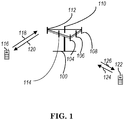
- FIG. 1 shows a multiple access wireless communication system according to one embodiment of the invention.
- An access network 100 includes multiple antenna groups, one including 104 and 106, another including 108 and 110, and an additional including 112 and 114. In FIG. 1 , only two antennas are shown for each antenna group, however, more or fewer antennas may be utilized for each antenna group.
- Access terminal 116 is in communication with antennas 112 and 114, where antennas 112 and 114 transmit information to access terminal 116 over forward link 120 and receive information from access terminal 116 over reverse link 118.
- Access terminal (AT) 122 is in communication with antennas 106 and 108, where antennas 106 and 108 transmit information to access terminal (AT) 122 over forward link 126 and receive information from access terminal (AT) 122 over reverse link 124.
- communication links 118, 120, 124 and 126 may use different frequency for communication.
- forward link 120 may use a different frequency then that used by reverse link 118.
- antenna groups each are designed to communicate to access terminals in a sector of the areas covered by access network 100.
- the transmitting antennas of access network 100 may utilize beamforming in order to improve the signal-to-noise ratio of forward links for the different access terminals 116 and 122. Also, an access network using beamforming to transmit to access terminals scattered randomly through its coverage causes less interference to access terminals in neighboring cells than an access network transmitting through a single antenna to all its access terminals.
- An access network may be a fixed station or base station used for communicating with the terminals and may also be referred to as an access point, a Node B, a base station, an enhanced base station, an evolved Node B (eNB), or some other terminology.
- An access terminal may also be called user equipment (UE), a wireless communication device, terminal, access terminal or some other terminology.
- FIG. 2 is a simplified block diagram of an embodiment of a transmitter system 210 (also known as the access network) and a receiver system 250 (also known as access terminal (AT) or user equipment (UE)) in a MIMO system 200.
- a transmitter system 210 also known as the access network
- a receiver system 250 also known as access terminal (AT) or user equipment (UE)
- traffic data for a number of data streams is provided from a data source 212 to a transmit (TX) data processor 214.
- TX transmit
- each data stream is transmitted over a respective transmit antenna.
- TX data processor 214 formats, codes, and interleaves the traffic data for each data stream based on a particular coding scheme selected for that data stream to provide coded data.
- the coded data for each data stream may be multiplexed with pilot data using OFDM techniques.
- the pilot data is typically a known data pattern that is processed in a known manner and may be used at the receiver system to estimate the channel response.
- the multiplexed pilot and coded data for each data stream is then modulated (i.e., symbol mapped) based on a particular modulation scheme (e.g., BPSK, QPSK, M-PSK, or M-QAM) selected for that data stream to provide modulation symbols.
- a particular modulation scheme e.g., BPSK, QPSK, M-PSK, or M-QAM
- the data rate, coding, and modulation for each data stream may be determined by instructions performed by processor 230.
- TX MIMO processor 220 may further process the modulation symbols (e.g., for OFDM).
- TX MIMO processor 220 then provides N T modulation symbol streams to N T transmitters (TMTR) 222a through 222t.
- TMTR TX MIMO processor 220 applies beamforming weights to the symbols of the data streams and to the antenna from which the symbol is being transmitted.
- Each transmitter 222 receives and processes a respective symbol stream to provide one or more analog signals, and further conditions (e.g., amplifies, filters, and upconverts) the analog signals to provide a modulated signal suitable for transmission over the MIMO channel.
- N T modulated signals from transmitters 222a through 222t are then transmitted from N T antennas 224a through 224t, respectively.
- the transmitted modulated signals are received by N R antennas 252a through 252r and the received signal from each antenna 252 is provided to a respective receiver (RCVR) 254a through 254r.
- Each receiver 254 conditions (e.g., filters, amplifies, and downconverts) a respective received signal, digitizes the conditioned signal to provide samples, and further processes the samples to provide a corresponding "received" symbol stream.
- An RX data processor 260 then receives and processes the N R received symbol streams from N R receivers 254 based on a particular receiver processing technique to provide N T "detected" symbol streams.
- the RX data processor 260 then demodulates, deinterleaves, and decodes each detected symbol stream to recover the traffic data for the data stream.
- the processing by RX data processor 260 is complementary to that performed by TX MIMO processor 220 and TX data processor 214 at transmitter system 210.
- a processor 270 periodically determines which pre-coding matrix to use (discussed below). Processor 270 formulates a reverse link message comprising a matrix index portion and a rank value portion.
- the reverse link message may comprise various types of information regarding the communication link and/or the received data stream.
- the reverse link message is then processed by a TX data processor 238, which also receives traffic data for a number of data streams from a data source 236, modulated by a modulator 280, conditioned by transmitters 254a through 254r, and transmitted back to transmitter system 210.
- the modulated signals from receiver system 250 are received by antennas 224, conditioned by receivers 222, demodulated by a demodulator 240, and processed by a RX data processor 242 to extract the reserve link message transmitted by the receiver system 250.
- Processor 230 determines which pre-coding matrix to use for determining the beamforming weights then processes the extracted message.
- FIG. 3 shows an alternative simplified functional block diagram of a communication device according to one embodiment of the invention.
- the communication device 300 in a wireless communication system can be utilized for realizing the UEs (or ATs) 116 and 122 in FIG. 1 or the base station (or AN) 100 in FIG. 1 , and the wireless communications system is preferably the NR system.
- the communication device 300 may include an input device 302, an output device 304, a control circuit 306, a central processing unit (CPU) 308, a memory 310, a program code 312, and a transceiver 314.
- the control circuit 306 executes the program code 312 in the memory 310 through the CPU 308, thereby controlling an operation of the communications device 300.
- the communications device 300 can receive signals input by a user through the input device 302, such as a keyboard or keypad, and can output images and sounds through the output device 304, such as a monitor or speakers.
- the transceiver 314 is used to receive and transmit wireless signals, delivering received signals to the control circuit 306, and outputting signals generated by the control circuit 306 wirelessly.
- the communication device 300 in a wireless communication system can also be utilized for realizing the AN 100 in FIG. 1 .
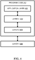
- FIG. 4 is a simplified block diagram of the program code 312 shown in FIG. 3 in accordance with one embodiment of the invention.
- the program code 312 includes an application layer 400, a Layer 3 portion 402, and a Layer 2 portion 404, and is coupled to a Layer 1 portion 406.
- the Layer 3 portion 402 generally performs radio resource control.
- the Layer 2 portion 404 generally performs link control.
- the Layer 1 portion 406 generally performs physical connections.
- next generation access technology aims to support the following three families of usage scenarios for satisfying both the urgent market needs and the more long-term requirements set forth by the ITU-R IMT-2020:
- An objective of the 5G study item on new radio access technology is to identify and develop technology components needed for new radio systems which should be able to use any spectrum band ranging at least up to 100 GHz.
- Supporting carrier frequencies up to 100GHz brings a number of challenges in the area of radio propagation. As the carrier frequency increases, the path loss also increases.
- the required cell coverage may be provided by forming a wide sector beam for transmitting downlink common channels.
- the cell coverage is reduced with same antenna gain.
- higher antenna gain is needed to compensate the increased path loss.
- larger antenna arrays are used to form high gain beams.
- the high gain beams being narrow compared to a wide sector beam, multiple beams for transmitting downlink common channels are needed to cover the required cell area.
- the number of concurrent high gain beams that access point is able to form may be limited by the cost and complexity of the utilized transceiver architecture. In practice, in higher frequencies, the number of concurrent high gain beams is much less than the total number of beams required to cover the cell area. In other words, the access point is able to cover only part of the cell area by using a subset of beams at any given time.
- beamforming is a signal processing technique used in antenna arrays for directional signal transmission/reception.
- a beam can be formed by combining elements in a phased array of antennas in such a way that signals at particular angles experience constructive interference while others experience destructive interference.
- Different beams can be utilized simultaneously using multiple arrays of antennas.
- Beamforming can be generally categorized into three types of implementation: digital beamforming, hybrid beamforming, and analog beamforming.
- digital beamforming the beam is generated on the digital domain, i.e. the weighting of each antenna element can be controlled by baseband (e.g. connected to a TXRU (Transceiver Units)). Therefore it is very easy to tune the beam direction of each subband differently across the system bandwidth. Also, to change beam direction from time to time does not require any switching time between OFDM (Orthogonal Frequency Division Multiplexing) symbols. All beams whose directions cover the whole coverage can be generated simultaneously. However, this structure requires (almost) one-to-one mapping between TXRU (transceiver/RF chain) and antenna element and is quite complicated as the number of antenna element increases and system bandwidth increases (also heat problem exists).
- the beam is generated on the analog domain, i.e. the weighting of each antenna element can be controlled by an amplitude/phase shifter in the RF (Radio Frequency) circuit. Since the weighing is purely controlled by the circuit, the same beam direction would apply on the whole system bandwidth. Also, if beam direction is to be changed, switching time is required.
- the number of beams generated simultaneous by an analog beamforming depends on the number of TXRU. Note that for a given size of array, the increase of TXRU may decrease the antenna element of each beam, such that wider beam would be generated.
- analog beamforming could avoid the complexity and heat problem of digital beamforming, while is more restricted in operation.
- Hybrid beamforming can be considered as a compromise between analog and digital beamforming, where the beam can come from both analog and digital domain.
- an eNB may have multiple TRPs (either centralized or distributed). Each TRP (Transmission/Reception Point) can form multiple beams. The number of beams and the number of simultaneous beams in the time/frequency domain depend on the number of antenna array elements and the RF (Radio Frequency) at the TRP.
- TRP Transmission/Reception Point
- the number of beams and the number of simultaneous beams in the time/frequency domain depend on the number of antenna array elements and the RF (Radio Frequency) at the TRP.
- Potential mobility type for NR can be listed as follows:
- 1 NR eNB (e.g. called gNB) corresponds to 1 or many TRPs.
- 3GPP TR 38.802 provides an introduction corresponding to beamforming as follows:
- beam management is defined as follows:
- Tx/Rx beam correspondence at TRP and UE are defined as Tx/Rx beam correspondence at TRP and UE:
- Tx/Rx beam correspondence is for convenience of discussion.
- the detailed performance conditions are up to RAN4.
- At least network triggered aperiodic beam reporting is supported under P-1, P-2, and P-3 related operations.
- NZP non-zero power
- a UE can be configured with the following high layer parameters for beam management:
- NR supports that UE can trigger mechanism to recover from beam failure.
- Beam failure event occurs when the quality of beam pair link(s) of an associated control channel falls low enough (e.g. comparison with a threshold, time-out of an associated timer).
- Mechanism to recover from beam failure is triggered when beam failure occurs.
- the beam pair link is used for convenience, and may or may not be used in specification.
- Network explicitly configures to UE with resources for UL transmission of signals for recovery purpose. Configurations of resources are supported where the base station is listening from all or partial directions, e.g., random access region.
- the UL transmission/resources to report beam failure can be located in the same time instance as PRACH (resources orthogonal to PRACH resources) or at a time instance (configurable for a UE) different from PRACH. Transmission of DL signal is supported for allowing the UE to monitor the beams for identifying new potential beams.
- NR supports beam management with and without beam-related indication.
- beam-related indication information pertaining to UE-side beamforming/receiving procedure used for CSI-RS-based measurement can be indicated through QCL to UE.
- NR supports using the same or different beams on control channel and the corresponding data channel transmissions.
- UE can be configured to monitor NR-PDCCH on M beam pair links simultaneously, where M ⁇ 1 and the maximum value of M may depend at least on UE capability.
- UE can be configured to monitor NR-PDCCH on different beam pair link(s) in different NR-PDCCH OFDM symbols.
- Parameters related to UE Rx beam setting for monitoring NR-PDCCH on multiple beam pair links are configured by higher layer signaling or MAC CE and/or considered in the search space design.
- NR supports indication of spatial QCL assumption between an DL RS antenna port(s), and DL RS antenna port(s) for demodulation of DL control channel.
- Candidate signaling methods for beam indication for a NR-PDCCH are MAC CE signaling, RRC signaling, DCI signaling, specification-transparent and/or implicit method, and combination of these signaling methods. Note that indication may not be needed for some cases.
- NR For reception of unicast DL data channel, NR supports indication of spatial QCL assumption between DL RS antenna port(s) and DMRS antenna port(s) of DL data channel.
- Information indicating the RS antenna port(s) is indicated via DCI (downlink grants).
- the information indicates the RS antenna port(s) which is QCL-ed with DMRS antenna port(s).
- Different set of DMRS antenna port(s) for the DL data channel can be indicated as QCL with different set of RS antenna port(s). Note that indication may not be needed for some cases.
- 3GPP TS 36.300 introduces the mechanism of Activation/Deactivation of SCells as follows:
- an activation/deactivation mechanism of SCells is supported (i.e. activation/deactivation does not apply to PCell).
- the UE When an SCell is deactivated, the UE does not need to receive the corresponding PDCCH or PDSCH, cannot transmit in the corresponding uplink, nor is it required to perform CQI measurements.
- the UE shall receive PDSCH and PDCCH (if the UE is configured to monitor PDCCH from this SCell), and is expected to be able to perform CQI measurements.
- E-UTRAN ensures that while PUCCH SCell is deactivated, SCells of secondary PUCCH group should not be activated.
- the activation/deactivation mechanism is based on the combination of a MAC control element and deactivation timers.
- the MAC control element carries a bitmap for the activation and deactivation of SCells: a bit set to 1 denotes activation of the corresponding SCell, while a bit set to 0 denotes deactivation.
- SCells can be activated and deactivated individually, and a single activation/deactivation command can activate/deactivate a subset of the SCells.
- One deactivation timer is maintained per SCell but one common value is configured per UE by RRC.
- the serving cells of the MCG other than the PCell can only be activated/deactivated by the MAC Control Element received on MCG, and the serving cells of the SCG other than PSCell can only be activated/ deactivated by the MAC Control Element received on SCG.
- the MAC entity applies the bitmap for the associated cells of either MCG or SCG.
- PSCell in SCG is always activated like the PCell (i.e. deactivation timer is not applied to PSCell). With the exception of PUCCH SCell, one deactivation timer is maintained per SCell but one common value is configured per CG by RRC.
- 3GPP TS 36.331 describes RRCConnectionReconfiguration and SCell addition or modification as follows:
- the RRCConnectionReconfiguration message is the command to modify an RRC connection. It may convey information for measurement configuration, mobility control, radio resource configuration (including RBs, MAC main configuration and physical channel configuration) including any associated dedicated NAS information and security configuration.
- sCellToAddModList if sCellIndex-r13 is present the UE shall ignore sCellIndex-r12. sCellIndex-r13 in sCellToAddModListExt-r13 shall not have same values as sCellIndex-r10 in sCellToAddModList-r10. sCellToAddModList, sCellToAddModListExt Indicates the SCell to be added or modified. Field sCellToAddModList is used to add the first 4 SCells with sCellIndex-r10 while sCellToAddModListExt is used to add the rest.
- E-UTRAN includes SCellToAddModListExt-v14xy it includes the same number of entries, and listed in the same order, as in SCellToAddModListExt-r13.
- sCellToAddModListSCG sCellToAddModListSCG-Ext Indicates the SCG cell to be added or modified.
- the field is used for SCG cells other than the PSCell (which is added/ modified by field pSCellToAddMod ) .
- Field sCellToAddModListSCG is used to add the first 4 SCells with sCellIndex-r10 while sCellToAddModListSCG-Ext is used to add the rest.
- sCellToReleaseListSCG sCellToReleaseListSCG-Ext Indicates the SCG cell to be released.
- the field is also used to release the PSCell e.g. upon change of PSCell, upon system information change for the PSCell.
- scg-Counter A counter used upon initial configuration of SCG security as well as upon refresh of S-K eNB .
- E-UTRAN includes the field upon SCG change when one or more SCG DRBs are configured. Otherwise E-UTRAN does not include the field.
- the UE shall:
- 3GPP TS 36.321 describes the procedure of Activation/Deactivation of SCells as follows:
- the network may activate and deactivate the configured SCells.
- the SpCell is always activated.
- the network activates and deactivates the SCell(s) by sending the Activation/Deactivation MAC control element described in subclause 6.1.3.8.
- the MAC entity maintains a sCellDeactivationTimer timer per configured SCell (except the SCell configured with PUCCH, if any) and deactivates the associated SCell upon its expiry.
- the same initial timer value applies to each instance of the sCellDeactivationTimer and it is configured by RRC.
- the configured SCells are initially deactivated upon addition and after a handover.
- the configured SCG SCells are initially deactivated after a SCG change.
- the MAC entity shall for each TTI and for each configured SCell:
- HARQ feedback for the MAC PDU containing Activation/Deactivation MAC control element shall not be impacted by PCell interruption due to SCell activation/deactivation [9].
- 3GPP TS 38.214 provides the introduction about reference signal (e.g. CSI-RS and SRS) as follows:
- CSI-RS Reference signal
- the UE can be configured with one or more CSI-RS resource set configuration(s) as indicated by the higher layer parameter ResourceSetConfig
- Each resource set consists of K ⁇ 1 non-zero power [or zero power transmission power resources].
- a UE shall perform aperiodic CSI reporting using PUSCH in slot n+Y on serving cell c upon decoding in slot n an uplink DCI format for serving cell c, where Y is indicated in the decoded uplink DCI.
- the higher layers-configured CSI Reporting Setting Indication is also indicated in the decoded uplink DCI and the associated CSI Measurement Links and CSI Resource Settings are higher layer configured.
- An aperiodic CSI report carried on the PUSCH supports wideband, partial band, and sub-band frequency granularities.
- CSI reporting on PUSCH can be multiplexed with uplink data on PUSCH.
- CSI reporting on PUSCH can also be performed without any multiplexing with uplink data from the UE.
- Type I CSI feedback is supported for CSI Reporting on PUSCH.
- Type I subband CSI is supported for CSI Reporting on the PUSCH.
- Type II CSI is supported for CSI Reporting on the PUSCH.
- a CSI report comprises up to two parts.
- the first part contains RI/CRI, CQI for the first codeword.
- the second part contains PMI and contains the CQI for the second codeword when RI>4.
- a CSI report comprises up to [two or three - TBD] parts.
- a UE is semi-statically configured by higher layers to perform periodic CSI Reporting on the PUCCH.
- a UE can be configured by higher layers for multiple periodic CSI Reports corresponding to one or more higher layer configured CSI Reporting Setting Indications, where the associated CSI Measurement Links and CSI Resource Settings are higher layer configured.
- Periodic CSI reporting on [TBD if short of long] PUCCH supports wideband and partial band frequency granularities.
- Periodic CSI reporting on the PUCCH supports Type I CSI.
- a UE shall perform semi-persistent CSI reporting on the PUCCH upon decoding [an uplink DCI format and/or decoding a MAC CE (one or both are TBD)].
- the uplink DCI format or the MAC CE will contain one or more CSI Reporting Setting Indications where the associated CSI Measurement Links and CSI Resource Settings are higher layer configured.
- Semi-persistent CSI reporting on the PUCCH supports Type I CSI.
- Semi-persistent CSI reporting on the Long PUCCH supports Type I Subband CSI.
- the UE can be configured with one or more Sounding Reference Symbol (SRS) resource sets as configured by the higher layer parameter SRS-ResourceSetConfig.
- SRS Sounding Reference Symbol
- a UE shall transmit SRS resources based on the following trigger types:
- At least one state of the DCI field is used to select at least one out of the configured SRS resources.
- SRS- ResourceConfig for [trigger type 0 and] for trigger type 1.
- 3GPP TS 38.211 describes the SS (Synchronization Signal) block as follows:
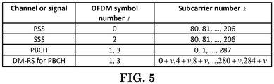
- an SS/PBCH block In the time domain, an SS/PBCH block consists of 4 OFDM symbols, numbered in increasing order from 0 to 3. In the frequency domain, an SS/PBCH block consists of 24 contiguous resource blocks with the subcarriers numbered in increasing order from 0 to 287, starting with the resource block with the lowest number.
- the UE shall assume the sequence of symbols d PSS (0),..., d PSS (126) constituting the primary synchronization signal to be scaled by a factor ⁇ SS to conform to the PSS power allocation specified in [5, TS 38.213] and mapped to resource elements ( k,l ) p, ⁇ in increasing order of k where k and l are given by Table 7.4.3.1-1 and represent the frequency and time indices, respectively, within one SS/PBCH block.
- the UE shall assume the sequence of symbols d SSS (0),..., d SSS (126) constituting the secondary synchronization signal to be scaled by a factor ⁇ SS to conform to the SSS power allocation specified in [5, TS 38.213] and mapped to resource elements ( k,l ) p, ⁇ in increasing order of k where k and l are given by Table 7.4.3.1-1 and represent the frequency and time indices, respectively, within one SS/PBCH block.
- the UE shall assume the sequence of complex-valued symbols d PBCH (0),..., d PBCH ( M symb -1) constituting the physical broadcast channel to be scaled by a factor ⁇ PBCH to conform to the PBCH power allocation specified in [5, TS 38.213] and mapped in sequence starting with d PBCH (0) to resource elements ( k,l ) p, ⁇ which meet all the following criteria:
- mapping to resource elements ( k,l ) p, ⁇ not reserved for other purposes shall be in increasing order of first the index k and then the index l , where k and l represent the frequency and time indices, respectively, within one SS/PBCH block and are given by Table 7.4.3.1-1.
- the UE shall assume
- the UE may assume that SS/PBCH blocks transmitted with the same block time index within a SS/PBCH burst set periodicity are quasi co-located with respect to Doppler spread, Doppler shift, average gain, average delay, and spatial Rx parameters.
- the UE shall not assume quasi co-location for any other SS/PBCH block transmissions.
- SCell Secondary Cell
- PDCCH Physical Downlink Control Channel
- PDSCH Physical Downlink Shared Channel
- CQI Channel Quality Indicator
- the network may activate or deactivate the configured SCell(s), e.g. by sending an SCell Activation/Deactivation MAC (Medium Access Control) CE (Control Element).
- SCell Activation/Deactivation MAC CE Medium Access Control CE
- the UE may need to apply some operation on the activated SCell. For example, for DL (Downlink), the UE may apply PDCCH monitoring on the activated SCell.
- the network may perform (or transmit) DL transmission via beamforming technique, i.e. the network may transmit DL signaling via a specific network beam(s) on a specific direction.
- the UE may need to know how to monitor PDCCH on the activated SCell, e.g. via which network beam(s) and/or UE beam(s).
- the UE may need to know how to perform (or receive) DL data transmission (e.g. PDSCH transmission) on the activated SCell.
- the UE may apply PUCCH (Physical Uplink Control Channel) transmission, e.g. for CQI reporting (e.g. to transmit CQI report) and/or scheduling request, (or reference signal transmission, e.g. SRS (Sounding Reference Signal)) on the activated SCell.
- PUCCH Physical Uplink Control Channel
- CQI reporting e.g. to transmit CQI report
- scheduling request e.g.
- reference signal transmission e.g. SRS (Sounding Reference Signal)
- the UE may need to determine how to perform (or transmit) PUCCH transmission, PUSCH (Physical Uplink Shared Channel) transmission and/or reference signal transmission, e.g. via which network beam(s) and/or UE beam(s).
- PUSCH Physical Uplink Shared Channel
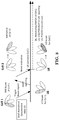
- FIG. 6 illustrates an example of activating an SCell.
- a UE is configured with at least two serving cells, including a PCell which is activated and an SCell which is deactivated.
- SCell Activation/Deactivation MAC CE via the PCell
- which beam(s) could be used for DL transmission and/or UL transmission in the SCell may be ambiguous.
- any DL transmission or UL transmission e.g. beam indication, data transmission, etc.
- the network could not transmit the beam indication via the SCell in this situation.
- the UE is configured with at least two serving cells including a first serving cell (e.g. PCell or PSCell) and a second serving cell (e.g. SCell), wherein the first serving cell is activated and the second serving cell is deactivated.
- a first serving cell e.g. PCell or PSCell
- a second serving cell e.g. SCell
- the network can transmit a beam indication to the UE.
- the beam indication can be used to derive which network beam(s) and/or UE beam(s) to be used in the second serving cell.
- the UE can follow the beam indication to perform (e.g. receive and/or transmit) DL and/or UL transmission on the second serving cell once the second serving cell is activated.
- the network may provide the beam indication when transmitting the SCell Activation/Deactivation MAC CE to the UE.
- the network may transmit a beam indication to the UE without triggering beam report.
- the network could determine the network beam(s) and/or the UE beam(s) for the SCell to the UE based on the measurement result of periodic beam report from the UE.
- the beam indication may be transmitted together with the SCell Activation/Deactivation MAC CE.
- the beam indication and the SCell Activation/Deactivation MAC CE can be transmitted individually.
- FIG. 7 shows an example of determining the network beam(s) and/or UE beam(s).
- the network may provide the beam indication after transmitting SCell Activation/Deactivation MAC CE to the UE.
- the network may trigger the UE to report (or feedback) information of beam measurement for the activated SCell.
- the network could transmit a beam indication to the UE.
- the UE could follow the beam indication to perform (e.g. receive and/or transmit) DL and/or UL transmission on the activated SCell.
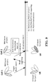
- FIG. 8 shows an example of determining the network beam(s) and/or UE beam(s) by triggering beam report when transmitting the SCell Activation/Deactivation MAC CE.
- the UE may not activate the SCell upon receiving the SCell Activation/Deactivation MAC CE, e.g. if the UE does not know which serving beams could be used.
- the UE may activate the SCell upon receiving the beam indication after receiving the SCell Activation/Deactivation MAC CE.
- the network may trigger the UE to report (or feedback) information of beam measurement of an SCell which is deactivated. After the UE reports (or feedbacks) the information of beam measurement, the network could determine whether to activate the SCell. If the network wants to activate the SCell, the network may transmit the SCell Activation/Deactivation MAC CE and transmit a beam indication to the UE. Preferably, the SCell Activation/Deactivation MAC CE and the beam indication may be transmitted together or separately.
- FIG. 9 shows an example of determining the network beam(s) and/or UE beam(s) by triggering beam report before transmitting the SCell Activation/Deactivation MAC CE.
- the signaling to trigger beam report may be the same signaling to transmit the SCell Activation/Deactivation MAC CE.
- the SCell Activation/Deactivation MAC CE may implicitly trigger beam report.
- the signaling to trigger beam report may be transmitted before the SCell Activation/Deactivation MAC CE, or after the SCell Activation/Deactivation MAC CE.
- the signaling to trigger beam report may be transmitted via an SCell which is previously activated. Furthermore, the signaling to trigger beam report may be transmitted via the PCell, PSCell, or SCell.
- the signaling to trigger beam report may include information of cell (e.g. cell index).
- the signaling to trigger beam report may indicate that the UE could report on which cell.
- the signaling to trigger beam report may indicate the UE could perform beam reporting (e.g. transmit beam report) on which cell.
- the signaling to trigger beam report may be transmitted via the cell which transmitted the SCell Activation/Deactivation MAC CE, or via the cell which is activated after the UE receiving the SCell Activation/Deactivation MAC CE.
- the signaling to trigger beam report may be transmitted via the cell which is not the cell transmitted the SCell Activation/Deactivation MAC CE, and not the cell which is activated after the UE receiving the SCell Activation/Deactivation MAC CE.
- the beam measurement may be triggered when the UE receives the indication to trigger beam report, or when the UE receives the SCell Activation/Deactivation MAC CE.
- the UE may perform the beam measurement. Then the UE could report beam information based on the beam measurement.
- the beam reporting may include an index of cell (e.g. sCellIndex) to indicate, for example, the content of the beam reporting is for which cell.
- the beam reporting may include a CQI, PMI (Pre-coding Matrix Indicator), RI (Rank Indicator), PTI (Precoding Type Indicator), and/or CRI (CSI-RS Resource Index) report.
- the beam reporting may include beam information of the SCell which will be activated, wherein the index of the SCell may be indicated via the signaling to trigger beam reporting.
- the beam reporting may include beam information (e.g. index associated with beam, and/or RSRP) of the cell(s) which is measured by the UE.
- the beam reporting may be transmitted on the cell which triggered the beam report, on the cell which transmitted the SCell Activation/Deactivation MAC CE, or on the cell which is activated after the UE receiving the SCell Activation/Deactivation MAC CE.
- the beam reporting may be transmitted via the cell which is not the cell transmitted the SCell Activation/Deactivation MAC CE and not the cell which is activated after the UE receiving the SCell Activation/Deactivation MAC CE.
- the beam indication could indicate the UE which network beam(s) and/or UE beam(s) could be used for DL and/or UL transmission.
- the beam indication may include information of network and/or UE beam(s).
- the beam indication may include an index of cell (e.g. sCellIndex) to indicate, for example, the beam indication is from which cell and/or to indicate the beam indication is for which cell.
- the beam indication may comprise an indicator of SS block(s), an indicator of CSI-RS, an indicator of SRS, and/or an indicator of beam reference signal.
- the beam indication may be transmitted via the cell which transmitted the SCell Activation/Deactivation MAC CE, the cell which transmitted the signaling to trigger beam report, or the cell which is the activated cell.
- the beam indication may be transmitted via any SCell which is previously activated, or via the PCell, PSCell, and/or SCell.
- the UE may need to apply some operations on the newly added SCell. For example, for DL, the UE may perform PDCCH monitoring on the added SCell. For UL, the UE may perform PUCCH transmission, e.g. for CQI reporting (e.g. to transmit CQI report) and/or scheduling request (or reference signal transmission, e.g. SRS) on the added SCell. Therefore, the UE may need to determine how to perform (e.g. receive and/or transmit) the DL and/or UL transmission, e.g.
- CQI reporting e.g. to transmit CQI report
- scheduling request or reference signal transmission, e.g. SRS
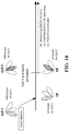
- FIG. 10 illustrates an example of adding an SCell which is initially activated.
- the network may trigger the UE to report (or feedback) information of beam measurement, e.g. reference signal measurement report.
- the network could indicate a beam indication to the UE. Then the UE could follow the beam indication to perform (e.g. receive and/or transmit) the DL and/or UL transmission on the added SCell.
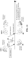
- FIG. 11 shows an example of determining the network beam(s) and/or UE beam(s) by triggering beam report when transmitting a signaling for SCell addition.
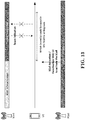
- the network may trigger the UE to report (or feedback) information of beam measurement of a cell which may be added to be an SCell by the network. After the UE reports (or feedbacks) the information of beam measurement (e.g. beam reporting), the network could determine whether to add the SCell. If the network wants to add the SCell, the network may transmit the SCell addition indication and indicate a beam indication to the UE. Preferably, the signaling for SCell addition and the beam indication may be transmitted together or separately.
- FIG. 12 shows an example of determining the network beam(s) and/or UE beam(s) by triggering beam report before transmitting a signaling for SCell addition.
- the signaling to trigger beam report may be the signaling to transmit the SCell addition.
- the signaling for SCell addition may implicitly trigger beam report.
- the signaling to trigger beam report may be transmitted before the signaling for SCell addition, or after the signaling for SCell addition.
- the signaling to trigger beam report may be transmitted via any SCell which is previously added, or via the PCell, PSCell, and/or SCell.
- the signaling to trigger beam report may include information of cell (e.g. cell index).
- the signaling to trigger beam report may indicate the UE could report on which cell.
- the signaling to trigger beam report may indicate the UE could perform beam reporting (e.g. transmit beam report) on which cell.
- the signaling to trigger beam report may be transmitted via the cell which transmitted the signaling for SCell addition.
- the signaling to trigger beam report may be transmitted via the cell which is activated after the UE receiving the signaling for SCell addition.
- the signaling to trigger beam report may be transmitted via the cell which is not the cell transmitted the signaling for SCell addition and not the cell which is activated after the UE receiving the signaling for SCell addition.
- the beam measurement may be triggered when the UE receives the indication to trigger beam report, or when the UE receives the signaling for SCell addition.
- the UE may perform the beam measurement. Then the UE could report beam information based on the beam measurement.
- the beam reporting may include an index of cell (e.g. sCellIndex) to indicate, for example, the content of the beam reporting is for which cell.
- the beam reporting may include a CQI, PMI, RI, PTI, and/or CRI report.
- the beam reporting may include beam information of the SCell which will be added, wherein the index of the SCell may be indicated via the signaling to trigger beam reporting.
- the beam reporting may include beam information (e.g. index associated with beam, and/or RSRP) of the cell(s) which is measured by the UE.
- the beam reporting may be transmitted on the cell which triggered the beam report, the cell which transmitted the signaling for SCell addition, or the cell which is activated after the UE receiving the signaling for SCell addition.
- the beam reporting may be transmitted via the cell which is not the cell transmitted the signaling for SCell addition and not the cell which is activated after the UE receiving the signaling for SCell addition.
- the beam indication could indicate the UE which network beam(s) and/or UE beam(s) could be used for DL and/or UL transmission.
- the beam indication may include information of network and/or UE beam(s).
- the beam indication may include an index of cell (e.g. sCellIndex) to indicate, for example, the beam indication is from which cell and/or to indicate the beam indication is for which cell.
- the beam indication may comprise an indicator of SS block(s), an indicator of CSI-RS, an indicator of SRS, or an indicator of beam reference signal.
- the beam indication may be transmitted via the cell which transmitted the signaling for SCell addition, the cell which transmitted the signaling to trigger beam report, or the cell which is the newly added cell.
- the beam indication may be transmitted via any SCell which is previously added, or the PCell, PSCell, and/or SCell.
- the network could transmit the beam indication via the activated serving cell (e.g. PCell and/or other activated SCell). Therefore, the beam indication may further include cell index(s), which may be used to indicate the beam indication is for which cell(s). With the cell index, the network can transmit the beam indication to the UE via any serving cell(s), e.g. cross-cell beam indication. For example, in FIG. 14 , the UE could receive the beam indication (including cell index) via the PCell, and the beam indication could be used to indicate beam information for the SCell. Thus, the UE could use the beam(s) for DL transmission or UL transmission in the SCell based on the beam indication.
- the activated serving cell e.g. PCell and/or other activated SCell.
- the beam indication may further include cell index(s), which may be used to indicate the beam indication is for which cell(s).
- the network can transmit the beam indication to the UE via any serving cell(s), e.g. cross-cell beam indication.
- the UE
- the beam indication may be transmitted via PHY signaling (e.g. DCI), MAC signaling (e.g. MAC control element), and/or RRC signaling (e.g. RRC configuration message).
- the beam indication may include an indicator of beam(s) (e.g. beam index) and/or a bitmap of beams (e.g. activation/activation for beams).
- the indicator of beam(s) may be used to indicate (or derive) which beam(s) could be used for DL transmission and/or UL transmission.
- the bitmap of beams may be used to indicate (or derive) one or multiple beam(s) could be used (or activated/deactivated) for DL transmission and/or UL transmission.
- the beam indication may be used to indicate (or derive) the beam(s) for DL transmission or UL transmission based on the (RRC) configuration for beam(s).
- whether the network triggers beam report for an SCell may be based on whether uplink of the UE in the SCell is synchronized or not. For example, if uplink of the UE in the SCell is synchronized, the network may trigger the UE to transmit beam report. As another example, if uplink of the UE in the SCell is not synchronized, the network may not trigger the UE to transmit beam report. Preferably, if uplink of the UE in the SCell is not synchronized, the network may trigger a random access procedure on the UE for the SCell.
- whether the network triggers beam report for an SCell to a UE may not be based on whether uplink of the UE in the SCell is synchronized or not.
- the network may trigger beam report for an SCell to a UE when uplink of the UE in the SCell is synchronized.
- the network may trigger beam report for an SCell to a UE when uplink of the UE in the SCell is not synchronized.
- whether the UE triggers beam report for an SCell when receiving the signal to trigger beam report for the SCell from network may be based on whether uplink of the UE in the SCell is synchronized or not. For example, if uplink of the UE in the SCell is synchronized, the UE may trigger beam port (e.g. measuring reference signal and transmitting beam reporting). As another example, if uplink of the UE in the SCell is not synchronized, the UE may not trigger beam report. Preferably, if uplink of the UE in the SCell is not synchronized, even if the UE receive the signaling to trigger beam report, the UE may not perform beam report procedure.
- whether the UE trigger beam report for an SCell when receiving the signal to trigger beam report for the SCell from network may not be based on whether uplink of the UE in the SCell is synchronized or not.
- the UE may trigger beam report for an SCell when uplink of the UE in the SCell is synchronized.
- the UE may trigger beam report for an SCell when uplink of the UE in the SCell is not synchronized.
- the signaling to trigger beam report and the beam indication are individually received by the UE.
- the UE may receive the signaling to trigger beam report, but may not receive the beam indication.
- the UE may receive the beam indication without beam reporting.
- the UE may receive the signaling to trigger beam report, then may transmit beam report, and then may receive the beam indication.
- the signaling to trigger beam report and the beam indication may be transmitted by different cells.
- the signaling to trigger beam report and the beam indication may be transmitted by the same cell.
- the UE mentioned above could be the UE with beamforming capability or the UE without UE beamforming capability.
- the UE may select SS block and/or CSI-RS for beam reporting, e.g. the UE may select the strongest beam pair link or beam(s).
- the UE may perform beam sweeping to receive the beam indication.
- the network may perform beam sweeping to receive the beam report.
- the network beam(s) may be associated with DL broadcast signal (e.g. SS block), DL reference signal (e.g. CSI-RS), and/or UL reference signal (e.g. SRS).
- the network beam(s) may be composed of network Rx beam(s) and/or network Tx beam(s).
- the network beam(s) may be composed of network DL beam(s) and/or network UL beam(s).
- the UE beam(s) may be associated with DL broadcast signal (e.g. SS block), DL reference signal (e.g. CSI-RS), and/or UL reference signal (e.g. SRS).
- the UE beam(s) may be composed of UE Rx beam(s) and/or UE Tx beam(s), or of UE DL beam(s) and/or UE UL beam(s).
- FIG. 15 is a flow chart 1500 according to one exemplary embodiment from the perspective of a UE configured with at least two serving cells, including a PCell which is activated and an SCell which is deactivated.
- the UE receives an SCell activation/deactivation MAC (Medium Access Control) control element to activate the SCell.
- the UE activates the SCell based on the SCell activation/deactivation MAC control element.
- the UE receives a beam indication by a MAC control element via the PCell, wherein the beam indication includes a cell index and the beam indication is used to derive at least one beam to be used in the SCell.
- the UE uses the at least one beam for a DL (Downlink) transmission or an UL (Uplink) transmission in the SCell.
- the DL transmission could include at least one of PDCCH (Physical Downlink Control Channel) transmission and PDSCH (Physical Downlink Shared Channel) transmission.
- PDCCH Physical Downlink Control Channel
- PDSCH Physical Downlink Shared Channel
- using the at least one beam for the DL transmission could include monitoring PDCCH via the at least one beam.
- using the at least one beam for the DL transmission could include receiving PDSCH transmission via the at least one beam.
- the UL transmission could include at least one of PUCCH (Physical Uplink Control Channel) transmission, CQI (Channel Quality Indicator) report transmission, scheduling request, reference signal transmission, and PUSCH (Physical Uplink Shared Channel) transmission.
- using the at least one beam for the UL transmission could include (i) transmitting PUCCH via the at least one beam, (ii) reporting CQI via the at least one beam, (iii) transmitting scheduling request via the at least one beam, (iv) transmitting reference signal (such as SRS) via the at least one beam, and/or (v) transmitting PUSCH via the at least one beam.
- PUCCH Physical Uplink Control Channel
- CQI Channel Quality Indicator
- PUSCH Physical Uplink Shared Channel
- the cell index could indicate that the beam indication is for which cell (such as the SCell).
- the at least one beam could be network beam(s) or UE beam(s).
- the device 300 includes a program code 312 stored in the memory 310.
- the CPU 308 could execute program code 312 to enable the UE (i) to receive an SCell activation/deactivation MAC control element to activate the SCell, (ii) to activate the SCell based on the SCell activation/deactivation MAC control element, (iii) to receive a beam indication by a MAC control element via the PCell, wherein the beam indication includes a cell index and the beam indication is used to derive at least one beam to be used in the SCell, and (iv) to use the at least one beam for a DL transmission or an UL transmission in the SCell. Furthermore, the CPU 308 can execute the program code 312 to perform all of the above-described actions and steps or others described herein.
- FIG. 16 is a flow chart 1600 according to one exemplary embodiment from the perspective of a network node.
- the network node configures a UE with at least two serving cells, including a PCell which is activated and an SCell which is deactivated.
- the network node transmits an SCell activation/deactivation MAC control element to activate the SCell.
- the network node transmits a beam indication by a MAC control element via the PCell, wherein the beam indication includes a cell index and the beam indication is used by the UE to derive at least one beam to be used in the SCell.
- the network node uses the at least one beam for DL transmission or UL transmission in the SCell.
- the DL transmission could include at least one of PDCCH transmission and PDSCH transmission.
- using the at least one beam for the DL transmission could include transmitting a PDCCH via the at least one beam.
- using the at least one beam for the DL transmission could include transmitting a PDSCH via the at least one beam.
- the UL transmission could include at least one of PUCCH transmission, CQI report transmission, scheduling request, reference signal transmission, and PUSCH transmission.
- using the at least one beam for the UL transmission could include (i) receiving PUCCH via the at least one beam, (ii) receiving CQI report via the at least one beam, (iii) receiving scheduling request via the at least one beam, (iv) receiving reference signal (such as SRS) via the at least one beam, and/or (v) receiving PUSCH via the at least one beam.
- the cell index could indicate that the beam indication is for which cell (such as the SCell).
- the at least one beam could be network beam(s) or UE beam(s).
- the device 300 includes a program code 312 stored in the memory 310.
- the CPU 308 could execute program code 312 to enable the network node (i) to configure a UE with at least two serving cells, including a PCell which is activated and an SCell which is deactivated, (ii) to transmit an SCell activation/deactivation MAC control element to activate the SCell, (iii) to transmit a beam indication by a MAC control element via the PCell, wherein the beam indication includes a cell index and the beam indication is used by the UE to derive at least one beam to be used in the SCell, and (iv) to use the at least one beam for DL transmission or UL transmission in the SCell.
- the CPU 308 can execute the program code 312 to perform all of the above-described actions and steps or others described herein.
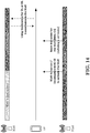
- FIG. 17 is a flow chart 1700 according to one exemplary embodiment from the perspective of a UE.
- the UE receives an SCell activation/deactivation MAC control element from a network node.
- the UE transmits a beam report to the network node.
- the UE receives a beam indication, wherein the beam indication includes an indicator of beam.
- the UE activates an SCell.
- the UE uses at least a beam for transmission on the SCell based on the beam indication.
- the device 300 includes a program code 312 stored in the memory 310.
- the CPU 308 could execute program code 312 to enable the UE (i) to receive an SCell activation/deactivation MAC control element from a network node, (ii) to transmit a beam report to the network node, (iii) to receive a beam indication, wherein the beam indication includes an indicator of beam, (iv) to activate an SCell, and (v) to use at least a beam for transmission on the SCell based on the beam indication.
- the CPU 308 can execute the program code 312 to perform all of the above-described actions and steps or others described herein.
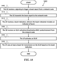
- FIG. 18 is a flow chart 1800 according to one exemplary embodiment from the perspective of a UE.
- the UE receives a signaling to trigger a beam report from a network node.
- the UE transmits the beam report to the network node.
- the UE receives a beam indication, wherein the beam indication includes an indicator of beam.
- the UE receives an SCell activation/deactivation MAC control element from the network node.
- the UE activates an SCell.
- the UE uses at least a beam for transmission on the SCell based on the beam indication.
- the device 300 includes a program code 312 stored in the memory 310.
- the CPU 308 could execute program code 312 to enable the UE (i) to receive a signaling to trigger a beam report from a network node, (ii) to transmit the beam report to the network node, (iii) to receive a beam indication, wherein the beam indication includes an indicator of beam, (iv) to receive an SCell activation/deactivation MAC control element from the network node, (v) to activate an SCell, and (vi) to use at least a beam for transmission on the SCell based on the beam indication.
- the CPU 308 can execute the program code 312 to perform all of the above-described actions and steps or others described herein.
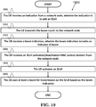
- FIG. 19 is a flow chart 1900 according to one exemplary embodiment from the perspective of a UE.
- the UE receives an indication from a network node, wherein the indication is to add an SCell.
- the UE transmits a beam report to the network node.
- the UE receives a beam indication, wherein the beam indication includes an indicator of beam.
- the UE activates an SCell.
- the UE uses at least a beam for transmission on the SCell based on the beam indication.
- the device 300 includes a program code 312 stored in the memory 310.
- the CPU 308 could execute program code 312 to enable the UE (i) to receive an indication from a network node, wherein the indication is to add an SCell, (ii) to transmit a beam report to the network node, (iii) to receive a beam indication, wherein the beam indication includes an indicator of beam, (iv) to activate an SCell, and (v) to use at least a beam for transmission on the SCell based on the beam indication.
- the CPU 308 can execute the program code 312 to perform all of the above-described actions and steps or others described herein.
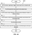
- FIG. 20 is a flow chart 2000 according to one exemplary embodiment from the perspective of a UE.
- the UE receives a signaling to trigger a beam report from a network node.
- the UE transmits the beam report to the network node.
- the UE receives a beam indication, wherein the beam indication includes an indicator of beam.
- the UE receives an indication from the network node, wherein the indication is to add an SCell.
- the UE activates an SCell.
- the UE uses at least a beam for transmission on the SCell based on the beam indication.
- the device 300 includes a program code 312 stored in the memory 310.
- the CPU 308 could execute program code 312 to enable the UE (i) to receive a signaling to trigger a beam report from a network node, (ii) to transmit the beam report to the network node, (iii) to receive a beam indication, wherein the beam indication includes an indicator of beam, (iv) to receive an indication from the network node, wherein the indication is to add an SCell, (v) to activate an SCell, and (vi) to use at least a beam for transmission on the SCell based on the beam indication.
- the CPU 308 can execute the program code 312 to perform all of the above-described actions and steps or others described herein.
- the SCell activation/deactivation MAC control element could be used to activate or deactivate at least an SCell.
- the SCell could be an SCell which is deactivated before activating.
- the SCell could be initially activated.
- the SCell could be an SCell which is not serving the UE before receiving the indication.
- the signaling may be received together with the SCell activation/deactivation MAC control element.
- the signaling may be received when receiving the SCell activation/deactivation MAC control element, before receiving the SCell activation/deactivation MAC control element, or after receiving the SCell activation/deactivation MAC control element.
- the signaling may be received from a cell which is transmitting the SCell activation/deactivation MAC control element.
- the beam indication may be received (or transmitted) together with the SCell activation/deactivation MAC control element.
- the beam indication may be received when receiving (or transmitting) the SCell activation/deactivation MAC control element, before receiving (or transmitting) the SCell activation/deactivation MAC control element, or after receiving (or transmitting) the SCell activation/deactivation MAC control element.
- the indication may be a RRC signaling (e.g. RRC connection reconfiguration).
- the indication may include an indicator of SCell (e.g. sCellIndex).
- the signaling may be received together with the indication.
- the signaling may be received when receiving the indication, before receiving the indication, or after receiving the indication.
- the signaling may be received from a cell which is transmitting the indication.
- the beam indication may be received together with the indication. The beam indication may be received when receiving the indication, before receiving the indication, or after receiving the indication.
- the signal could trigger beam reporting.
- the UE may perform beam measurement.
- the signaling may be received from the SCell or a PCell.
- the signaling may be received from a cell which is not the SCell.
- the signaling may include an indicator of cell(s), e.g. cell index.
- the beam report could be for measuring at least a reference signal associated with a beam and to report a result of measurement.
- the beam report may include an indicator of at least a beam, an indicator of a cell (e.g. cell index), an information of reference signal receiving power, and/or beam information of any cell which is measured by the UE.
- the beam indication may include an indicator of at least a beam and/or an indicator of a cell (e.g. cell index).
- the at least one beam could be composed of at least a network beam and/or a UE beam.
- the at least one beam may be associated with a DL broadcast signal (e.g. SS block), a DL reference signal (e.g. CSI-RS), or a UL reference signal (e.g. SRS).
- a DL broadcast signal e.g. SS block
- a DL reference signal e.g. CSI-RS
- a UL reference signal e.g. SRS
- the transmission may be a DL transmission or an UL transmission.
- the UE may perform a DL data transmission, may perform a UL data transmission, may monitor PDCCH on the SCell, and/or may perform measurement of a reference signal. If the SCell is activated, the UE may report CQI, PMI, RI, PTI, and/or CRI on the SCell. In addition, the UE may perform PUCCH transmission on the SCell.
- the reference signal could be a SS block, a CSI-RS, or any reference signal related to beam.
- concurrent channels may be established based on pulse repetition frequencies.
- concurrent channels may be established based on pulse position or offsets.
- concurrent channels may be established based on time hopping sequences.
- concurrent channels may be established based on pulse repetition frequencies, pulse positions or offsets, and time hopping sequences.
- the various illustrative logical blocks, modules, and circuits described in connection with the aspects disclosed herein may be implemented within or performed by an integrated circuit ("IC"), an access terminal, or an access point.
- the IC may comprise a general purpose processor, a digital signal processor (DSP), an application specific integrated circuit (ASIC), a field programmable gate array (FPGA) or other programmable logic device, discrete gate or transistor logic, discrete hardware components, electrical components, optical components, mechanical components, or any combination thereof designed to perform the functions described herein, and may execute codes or instructions that reside within the IC, outside of the IC, or both.
- a general purpose processor may be a microprocessor, but in the alternative, the processor may be any conventional processor, controller, microcontroller, or state machine.
- a processor may also be implemented as a combination of computing devices, e.g., a combination of a DSP and a microprocessor, a plurality of microprocessors, one or more microprocessors in conjunction with a DSP core, or any other such configuration.
- a software module e.g., including executable instructions and related data
- other data may reside in a data memory such as RAM memory, flash memory, ROM memory, EPROM memory, EEPROM memory, registers, a hard disk, a removable disk, a CD-ROM, or any other form of computer-readable storage medium known in the art.
- a sample storage medium may be coupled to a machine such as, for example, a computer/processor (which may be referred to herein, for convenience, as a "processor") such the processor can read information (e.g., code) from and write information to the storage medium.
- a sample storage medium may be integral to the processor.
- the processor and the storage medium may reside in an ASIC.
- the ASIC may reside in user equipment.
- the processor and the storage medium may reside as discrete components in user equipment.
- any suitable computer-program product may comprise a computer-readable medium comprising codes relating to one or more of the aspects of the disclosure.
- a computer program product may comprise packaging materials.
Landscapes
- Engineering & Computer Science (AREA)
- Signal Processing (AREA)
- Computer Networks & Wireless Communication (AREA)
- Mobile Radio Communication Systems (AREA)
Applications Claiming Priority (1)
| Application Number | Priority Date | Filing Date | Title |
|---|---|---|---|
| US201762560949P | 2017-09-20 | 2017-09-20 |
Publications (2)
| Publication Number | Publication Date |
|---|---|
| EP3461025A1 true EP3461025A1 (de) | 2019-03-27 |
| EP3461025B1 EP3461025B1 (de) | 2020-03-04 |
Family
ID=63667690
Family Applications (1)
| Application Number | Title | Priority Date | Filing Date |
|---|---|---|---|
| EP18194536.1A Active EP3461025B1 (de) | 2017-09-20 | 2018-09-14 | Verfahren und vorrichtung zur strahlbestimmung in einem drahtloskommunikationssystem |
Country Status (7)
| Country | Link |
|---|---|
| US (2) | US11240809B2 (de) |
| EP (1) | EP3461025B1 (de) |
| JP (1) | JP6694032B2 (de) |
| KR (1) | KR102166103B1 (de) |
| CN (1) | CN109788564B (de) |
| ES (1) | ES2790275T3 (de) |
| TW (1) | TWI679907B (de) |
Cited By (5)
| Publication number | Priority date | Publication date | Assignee | Title |
|---|---|---|---|---|
| WO2021046106A1 (en) * | 2019-09-04 | 2021-03-11 | Qualcomm Incorporated | Triggering reference signals in wireless networks |
| WO2021161065A1 (en) * | 2020-02-11 | 2021-08-19 | Nokia Technologies Oy | Methods and apparatuses for beam management reporting |
| WO2024054355A1 (en) * | 2022-09-06 | 2024-03-14 | Qualcomm Incorporated | Power efficient sub-thz deployment based on inter-band carrier aggregation |
| US12225452B2 (en) | 2019-09-30 | 2025-02-11 | Huawei Technologies Co., Ltd. | Signal transmission method and apparatus |
| EP3700254B1 (de) * | 2017-10-20 | 2025-12-03 | NTT DoCoMo, Inc. | Benutzerendgerät und drahtloskommunikationsverfahren |
Families Citing this family (63)
| Publication number | Priority date | Publication date | Assignee | Title |
|---|---|---|---|---|
| US10879985B2 (en) * | 2017-11-16 | 2020-12-29 | Ofinno, Llc | Channel state information report on bandwidth part |
| KR102463553B1 (ko) * | 2018-01-12 | 2022-11-04 | 삼성전자 주식회사 | 차세대 통신 시스템에서 빔 정보 보고 방법 및 장치 |
| JP7064006B2 (ja) * | 2018-02-15 | 2022-05-09 | テレフオンアクチーボラゲット エルエム エリクソン(パブル) | セミパーシステントsrsのための空間的関係の効率的なmac ceインジケーション |
| US10855363B2 (en) | 2018-05-07 | 2020-12-01 | Wilson Electronics, Llc | Multiple-input multiple-output (MIMO) repeater system |
| EP3576312A1 (de) | 2018-05-30 | 2019-12-04 | FRAUNHOFER-GESELLSCHAFT zur Förderung der angewandten Forschung e.V. | Auf doppler-delay-codebuch basierende vorcodierung und csi-rückmeldung für drahtloskommunikationssysteme |
| CN110662252B (zh) * | 2018-06-29 | 2022-04-05 | 成都华为技术有限公司 | 一种通信方法及装置 |
| WO2020024218A1 (en) * | 2018-08-02 | 2020-02-06 | Mediatek Singapore Pte. Ltd. | Standalone sss for rrm and channel estimation enhancement |
| US12074814B2 (en) * | 2018-09-27 | 2024-08-27 | Beijing Xiaomi Mobile Software Co., Ltd. | Measurement configuration method, apparatus, devices, system, and storage medium |
| US11962539B2 (en) * | 2018-11-08 | 2024-04-16 | Apple Inc. | Techniques in adaptive in-sync and out-of-sync classification based on channel parameter estimation in new radio |
| CN111385078B (zh) | 2018-12-29 | 2021-08-13 | 成都华为技术有限公司 | 一种辅助小区激活的方法和通信装置 |
| WO2020159172A1 (ko) * | 2019-02-01 | 2020-08-06 | 엘지전자 주식회사 | 무선 통신 시스템에서 단말의 빔 실패 보고 방법 및 이를 지원하는 단말 및 기지국 |
| WO2020164115A1 (en) * | 2019-02-15 | 2020-08-20 | Mediatek Singapore Pte. Ltd. | Methods and apparatus of scell activation in new radio system |
| CN111278125B (zh) * | 2019-03-29 | 2023-04-18 | 维沃移动通信有限公司 | 传输方法、终端设备及网络侧设备 |
| WO2020212739A1 (en) * | 2019-04-18 | 2020-10-22 | Telefonaktiebolaget Lm Ericsson (Publ) | Virtual beam sweeping for a physical random access channel in new radio and long term evolution active antenna systems |
| US11546090B2 (en) * | 2019-05-02 | 2023-01-03 | Ofinno, Llc | Hybrid automatic repeat request process |
| US11627562B2 (en) | 2019-05-10 | 2023-04-11 | Qualcomm Incorporated | Multi-panel activation/deactivation status reporting |
| WO2020231853A1 (en) * | 2019-05-10 | 2020-11-19 | Apple Inc. | Synchronization signal block (ssb) based beam measurement and reporting in 5g nr |
| KR102814106B1 (ko) * | 2019-05-16 | 2025-05-29 | 엘지전자 주식회사 | 무선 통신 시스템에서 빔 정보를 보고 하는 방법 및 이를 위한 장치 |
| CN112055374B (zh) * | 2019-06-06 | 2022-05-17 | 华为技术有限公司 | 用于激活辅小区的方法和装置 |
| US12057917B2 (en) * | 2019-06-21 | 2024-08-06 | Ntt Docomo, Inc. | Terminal with beam failure detection and recovery procedure |
| WO2021020590A1 (en) * | 2019-07-26 | 2021-02-04 | Sharp Kabushiki Kaisha | User equipments, base stations, and methods |
| CN112399430A (zh) | 2019-08-15 | 2021-02-23 | 索尼公司 | 无线通信系统中的用户设备、电子设备、方法及存储介质 |
| EP4401334B1 (de) | 2019-08-15 | 2025-10-29 | Guangdong Oppo Mobile Telecommunications Corp., Ltd. | Drahtloskommunikationsverfahren, endgerätevorrichtung und netzwerkvorrichtung |
| CN114270763B (zh) * | 2019-08-16 | 2024-05-14 | 瑞典爱立信有限公司 | 全带宽传输的探测参考信号配置 |
| US11445514B2 (en) * | 2019-08-23 | 2022-09-13 | Qualcomm Incorporated | Beam determination prior to beam activation indication |
| US12563410B2 (en) * | 2019-08-27 | 2026-02-24 | Samsung Electronics Co., Ltd. | Method and apparatus for multi-beam operations |
| CN112566264B (zh) | 2019-09-25 | 2022-07-22 | 维沃移动通信有限公司 | 一种参考信号传输方法及设备 |
| EP4057670A4 (de) * | 2019-11-05 | 2023-09-06 | Beijing Xiaomi Mobile Software Co., Ltd. | Verfahren und vorrichtung zum zuweisen von strahlenausfall-anforderungsressourcen und speichermedium |
| WO2021087994A1 (zh) * | 2019-11-08 | 2021-05-14 | 华为技术有限公司 | 一种上行传输的方法、设备及存储介质 |
| US11665696B2 (en) * | 2019-12-13 | 2023-05-30 | Qualcomm Incorporated | Action time for applying downlink control information based beam and reference signal activation command |
| CN115066943A (zh) * | 2020-02-04 | 2022-09-16 | 株式会社Ntt都科摩 | 终端、无线通信方法以及基站 |
| CN115103460A (zh) * | 2020-03-12 | 2022-09-23 | 展讯通信(上海)有限公司 | 辅小区组的激活方法及装置、存储介质、ue、基站 |
| JP7211541B2 (ja) | 2020-03-28 | 2023-01-24 | 日本電気株式会社 | Ue、無線局、及び方法 |
| WO2021203315A1 (en) * | 2020-04-08 | 2021-10-14 | Qualcomm Incorporated | Determining uplink default beam for multiple-input multiple-output (mimo) |
| CN115039475B (zh) * | 2020-04-11 | 2025-04-01 | 中兴通讯股份有限公司 | 一种用于改进的探测参考信号(srs)开销和灵活重用方案的方法和系统 |
| US11863281B2 (en) * | 2020-04-30 | 2024-01-02 | Qualcomm Incorporated | Methods and apparatus to facilitate cross-carrier beam association |
| WO2021232337A1 (en) * | 2020-05-21 | 2021-11-25 | Nokia Shanghai Bell Co., Ltd. | Beam failure recovery in secondary cell activation |
| EP4162752A4 (de) * | 2020-07-29 | 2024-02-07 | Apple Inc. | Subträgerabstandsbeschränkung für ssb, csi-rs für l3-mobilität und pdcch/pdsch |
| WO2022036498A1 (en) * | 2020-08-17 | 2022-02-24 | Qualcomm Incorporated | Beam management for a secondary cell group in a dormant state |
| KR20220037643A (ko) * | 2020-09-18 | 2022-03-25 | 삼성전자주식회사 | 무선통신시스템에서 부 기지국을 비활성화와 활성화하는 방법 및 장치 |
| CN114339890A (zh) * | 2020-09-29 | 2022-04-12 | 维沃移动通信有限公司 | 通信资源激活方法、终端及网络侧设备 |
| EP4222913A2 (de) * | 2020-10-30 | 2023-08-09 | Huawei Technologies Co., Ltd. | Vorrichtung und verfahren für verbesserungen von sekundärzellen (scell) in der drahtlosen kommunikation |
| US11757503B2 (en) * | 2020-12-11 | 2023-09-12 | Qualcomm Incorporated | UE panel specific beam application time |
| US20240147332A1 (en) * | 2020-12-24 | 2024-05-02 | Lenovo (Beijing) Limited | Methods and apparatuses for deactivating and activating a secondary cell group (scg) in a multiradio dual connectivity (mr-dc) scenario |
| CN116648972A (zh) * | 2020-12-24 | 2023-08-25 | 华为技术有限公司 | 用于灵活利用射频的方法和装置 |
| CN116686227A (zh) * | 2021-01-05 | 2023-09-01 | 捷开通讯(深圳)有限公司 | 一种用于载波聚合的上下行波束指示方法及通信设备 |
| EP4266730A4 (de) * | 2021-01-14 | 2024-02-28 | Huawei Technologies Co., Ltd. | Verfahren und vorrichtung zum melden und empfangen von strahlinformationen |
| CN116830655A (zh) * | 2021-01-15 | 2023-09-29 | 苹果公司 | 基于触发消息的与PSCell的切换 |
| CN116746220A (zh) * | 2021-01-21 | 2023-09-12 | 联想(北京)有限公司 | 用于去激活的sn情况下的波束失败检测及恢复过程的方法及设备 |
| EP4285500A4 (de) * | 2021-03-31 | 2025-02-05 | Apple Inc. | Verfahren und vorrichtung für ul-transmis-sion mit multi-trp |
| KR20230162980A (ko) * | 2021-04-02 | 2023-11-29 | 지티이 코포레이션 | 인공 지능을 사용하여 보고 및 빔 관리를 위한 시스템 및 방법 |
| WO2022226741A1 (en) * | 2021-04-26 | 2022-11-03 | Nokia Shanghai Bell Co., Ltd. | Mechanism for delivering beam information |
| CN115606228B (zh) * | 2021-05-11 | 2026-03-17 | 苹果公司 | 针对pucch辅小区激活的波束信息报告 |
| WO2022261923A1 (en) * | 2021-06-18 | 2022-12-22 | Lenovo (Beijing) Limited | Resource measurement restriction for beam management |
| BR112023027315A2 (pt) * | 2021-06-24 | 2024-03-12 | Beijing Xiaomi Mobile Software Co Ltd | Método para determinar um tempo de aplicação de um feixe, dispositivo de comunicação, e, meio de armazenamento legível por computador tendo instruções armazenadas no mesmo |
| US20230043826A1 (en) * | 2021-08-04 | 2023-02-09 | Qualcomm Incorporated | Periodic reference signal (rs) and rs availability indication signaling for fast activation of secondary cells |
| US12402139B2 (en) * | 2021-08-05 | 2025-08-26 | Apple Inc. | Fast secondary cell activation with temporary reference signals |
| CN117643146A (zh) * | 2021-10-22 | 2024-03-01 | Oppo广东移动通信有限公司 | 无线通信方法、终端设备和网络设备 |
| US20250105906A1 (en) * | 2022-03-25 | 2025-03-27 | Qualcomm Incorporated | Beam application time with bandwidth part switching in wireless communications |
| US12375976B2 (en) * | 2022-04-29 | 2025-07-29 | Qualcomm Incorporated | L1/L2 inter-cell mobility and CA |
| EP4543092A1 (de) * | 2022-06-20 | 2025-04-23 | LG Electronics Inc. | S-zell-aktivierung |
| WO2024026857A1 (en) * | 2022-08-05 | 2024-02-08 | Nokia Shanghai Bell Co., Ltd. | Data transmission at scell activation |
| CN120188405A (zh) * | 2022-11-07 | 2025-06-20 | 上海诺基亚贝尔股份有限公司 | 用于小区激活的波束信息触发 |
Citations (3)
| Publication number | Priority date | Publication date | Assignee | Title |
|---|---|---|---|---|
| WO2014112783A1 (en) * | 2013-01-16 | 2014-07-24 | Lg Electronics Inc. | Method and apparatus for configuring cell in wireless communication system |
| WO2017084607A1 (zh) * | 2015-11-20 | 2017-05-26 | 华为技术有限公司 | 一种下行同步的方法、装置及系统 |
| EP3200498A1 (de) * | 2014-09-23 | 2017-08-02 | Huawei Technologies Co. Ltd. | Trägerkonfigurationsverfahren, basisstation und benutzervorrichtung |
Family Cites Families (31)
| Publication number | Priority date | Publication date | Assignee | Title |
|---|---|---|---|---|
| EP2553963B1 (de) * | 2010-04-02 | 2020-07-22 | InterDigital Patent Holdings, Inc. | Verfahren und vorrichtung zur kommunikationsunterstützung über einen relaisknoten |
| US8885569B2 (en) | 2011-12-19 | 2014-11-11 | Ofinno Technologies, Llc | Beamforming signaling in a wireless network |
| KR102007846B1 (ko) * | 2012-01-26 | 2019-08-06 | 엘지전자 주식회사 | 제어 정보 송수신 방법 및 이를 위한 장치 |
| US9730097B2 (en) | 2012-07-25 | 2017-08-08 | Mediatek Inc. | Method of efficient blind SCell activation |
| US10172102B2 (en) * | 2013-12-22 | 2019-01-01 | Lg Electronics Inc. | Method for power headroom reporting and device therefor |
| CN110932835B (zh) * | 2014-01-29 | 2023-07-21 | 北京三星通信技术研究有限公司 | 处理基站间载波聚合的激活/去激活的方法及设备 |
| US10141983B2 (en) | 2014-05-08 | 2018-11-27 | Samsung Electronics Co., Ltd. | Method for activating pSCell and SCell in mobile communication system supporting dual connectivity |
| KR102349611B1 (ko) * | 2014-10-10 | 2022-01-11 | 삼성전자 주식회사 | 무선 통신 시스템에서 셀 설정 방법 및 장치 |
| WO2016065068A2 (en) * | 2014-10-21 | 2016-04-28 | Intel IP Corporation | Methods and apparatuses to form self-organized multi-hop millimeter wave backhaul links |
| CN107211296B (zh) | 2015-01-20 | 2020-11-03 | Lg电子株式会社 | 用于在无线通信系统中激活/停用小区的方法及其装置 |
| KR101728118B1 (ko) * | 2015-01-26 | 2017-04-18 | 아서스테크 컴퓨터 인코포레이션 | 무선 통신 시스템에서 업링크 전송을 처리하기 위한 방법 및 장치 |
| WO2016144055A1 (en) * | 2015-03-06 | 2016-09-15 | Samsung Electronics Co., Ltd. | Method and apparatus for performing and reporting measurements by user equipment configured with multiple carriers in mobile communication systems |
| US10104658B2 (en) * | 2015-06-12 | 2018-10-16 | Asustek Computer Inc. | Method and apparatus for delivery of control signaling in a wireless communication system |
| WO2017022870A1 (en) * | 2015-08-03 | 2017-02-09 | Samsung Electronics Co., Ltd. | Method and apparatus for initial access in wireless communication system |
| WO2017030478A1 (en) | 2015-08-17 | 2017-02-23 | Telefonaktiebolaget Lm Ericsson (Publ) | Activation of cells |
| US10674535B2 (en) * | 2015-11-13 | 2020-06-02 | Futurewei Technologies, Inc. | Device, network, and method for communications with opportunistic transmission and reception |
| US10270514B2 (en) * | 2016-01-14 | 2019-04-23 | Samsung Electronics Co., Ltd. | Method and apparatus for generating beam measurement information in a wireless communication system |
| JP2019054305A (ja) * | 2016-01-26 | 2019-04-04 | シャープ株式会社 | 基地局装置、端末装置および通信方法 |
| US10749577B2 (en) | 2016-03-01 | 2020-08-18 | Apple Inc. | Enabling a secondary cell in a massive MIMO system |
| KR20230128391A (ko) * | 2016-03-03 | 2023-09-04 | 인터디지탈 패튼 홀딩스, 인크 | 빔 포밍 기반의 시스템에서의 빔 제어를 위한 방법및 장치 |
| EP3488646B1 (de) * | 2016-07-20 | 2021-04-21 | Convida Wireless, LLC | Mobilität für funkgeräte mit beamformierung und beamauswahl |
| US11063717B2 (en) * | 2016-08-08 | 2021-07-13 | Lg Electronics Inc. | Channel state information transmitting method and user equipment, and channel state information receiving method and base station |
| US9900891B1 (en) * | 2016-12-20 | 2018-02-20 | Qualcomm Incorporated | Fallback beam selection procedure during failure of beam change instruction reception |
| US10194410B2 (en) * | 2017-02-16 | 2019-01-29 | Qualcomm Incorporated | Synchronization signal blocks |
| US11044650B2 (en) * | 2017-03-23 | 2021-06-22 | Convida Wireless, Llc | Downlink measurement design in new radio |
| US10972152B2 (en) * | 2017-03-24 | 2021-04-06 | Nokia Technologies Oy | Beam-based radio link monitoring |
| WO2018203679A1 (ko) * | 2017-05-04 | 2018-11-08 | 엘지전자(주) | 무선 통신 시스템에서 빔을 이용하여 신호를 송수신하는 방법 및 이를 위한 장치 |
| EP3527009B1 (de) * | 2017-05-04 | 2020-04-29 | Ofinno, LLC | Rach-leistungsversatz |
| US10820271B2 (en) * | 2017-07-25 | 2020-10-27 | FG Innovation Company Limited | Method and apparatus of power saving for discontinuous reception |
| EP4465551A3 (de) * | 2017-08-09 | 2025-05-07 | InterDigital Patent Holdings, Inc. | Verfahren und systeme zur strahlwiederherstellung und -verwaltung |
| CN111316706B (zh) * | 2017-11-14 | 2022-03-18 | 鸿颖创新有限公司 | 用于具有多分量载波的网络辅助传输的方法、设备和系统 |
-
2018
- 2018-09-14 ES ES18194536T patent/ES2790275T3/es active Active
- 2018-09-14 EP EP18194536.1A patent/EP3461025B1/de active Active
- 2018-09-14 JP JP2018172042A patent/JP6694032B2/ja active Active
- 2018-09-14 US US16/131,598 patent/US11240809B2/en active Active
- 2018-09-14 TW TW107132545A patent/TWI679907B/zh active
- 2018-09-14 CN CN201811076030.5A patent/CN109788564B/zh active Active
- 2018-09-14 KR KR1020180110249A patent/KR102166103B1/ko active Active
-
2021
- 2021-12-16 US US17/553,504 patent/US20220110109A1/en not_active Abandoned
Patent Citations (4)
| Publication number | Priority date | Publication date | Assignee | Title |
|---|---|---|---|---|
| WO2014112783A1 (en) * | 2013-01-16 | 2014-07-24 | Lg Electronics Inc. | Method and apparatus for configuring cell in wireless communication system |
| EP3200498A1 (de) * | 2014-09-23 | 2017-08-02 | Huawei Technologies Co. Ltd. | Trägerkonfigurationsverfahren, basisstation und benutzervorrichtung |
| WO2017084607A1 (zh) * | 2015-11-20 | 2017-05-26 | 华为技术有限公司 | 一种下行同步的方法、装置及系统 |
| EP3370380A1 (de) * | 2015-11-20 | 2018-09-05 | Huawei Technologies Co., Ltd. | Verfahren, vorrichtung und system downlink-synchronisation |
Non-Patent Citations (15)
| Title |
|---|
| "Evolved Universal Terrestrial Radio Access (E-UTRA) and Evolved Universal Terrestrial Radio Access Network (E-UTRAN); Overall description; Stage 2", TS 36.300 |
| "Evolved Universal Terrestrial Radio Access (E-UTRA); Medium Access Control (MAC) protocol specification", 3GPP RAN2#94 MEETING MINUTE; TS 36.321 |
| "Evolved Universal Terrestrial Radio Access (E-UTRA); Radio Resource Control (RRC); Protocol specification", TS 36.331 |
| "NR; Physical channels and modulation (Release 15", TS 38.211 |
| "NR; Physical layer procedures for data (Release 15", TS 38.214 |
| "Study on New Radio Access Technology Physical Layer Aspects", TR 38.802 |
| ASUSTEK: "Discussion on UL Beam Management", vol. RAN WG1, no. Nagoya, Japan; 20170918 - 20170921, 17 September 2017 (2017-09-17), XP051340003, Retrieved from the Internet <URL:http://www.3gpp.org/ftp/Meetings_3GPP_SYNC/RAN1/Docs/> [retrieved on 20170917] * |
| ERICSSON: "Active Mode Mobility in NR: SINR drops in higher frequencies", R2-162762 |
| ERICSSON: "Analysis of beam indication signalling options", vol. RAN WG1, no. Nagoya, Japan; 20170918 - 20170921, 12 September 2017 (2017-09-12), XP051329956, Retrieved from the Internet <URL:http://www.3gpp.org/ftp/tsg_ran/WG1_RL1/TSGR1_AH/NR_AH_1709/Docs/> [retrieved on 20170912] * |
| FINAL CHAIRMAN'S NOTE OF 3GPP TSG RAN WG1 MEETING #90, 21 August 2017 (2017-08-21) |
| FINAL REPORT OF 3GPP TSG RAN WG1 #88BIS, 3 April 2017 (2017-04-03) |
| FINAL REPORT OF 3GPP TSG RAN WG1 #89, 15 May 2017 (2017-05-15) |
| INTEL: "Beam support in NR", R2-162709 |
| NOKIA; ALCATEL-LUCENT: "Beam Forming Impacts", R2-162366 |
| SAMSUNG: "Discussion on terminology of beamforming based high frequency NR", R2-163716 |
Cited By (9)
| Publication number | Priority date | Publication date | Assignee | Title |
|---|---|---|---|---|
| EP3700254B1 (de) * | 2017-10-20 | 2025-12-03 | NTT DoCoMo, Inc. | Benutzerendgerät und drahtloskommunikationsverfahren |
| WO2021046106A1 (en) * | 2019-09-04 | 2021-03-11 | Qualcomm Incorporated | Triggering reference signals in wireless networks |
| CN114365446A (zh) * | 2019-09-04 | 2022-04-15 | 高通股份有限公司 | 触发无线网络中的参考信号 |
| US11570796B2 (en) | 2019-09-04 | 2023-01-31 | Qualcomm Incorporated | Triggering reference signals in wireless networks |
| CN114365446B (zh) * | 2019-09-04 | 2024-11-08 | 高通股份有限公司 | 触发无线网络中的参考信号 |
| US12225452B2 (en) | 2019-09-30 | 2025-02-11 | Huawei Technologies Co., Ltd. | Signal transmission method and apparatus |
| WO2021161065A1 (en) * | 2020-02-11 | 2021-08-19 | Nokia Technologies Oy | Methods and apparatuses for beam management reporting |
| US12520182B2 (en) | 2020-02-11 | 2026-01-06 | Nokia Technologies Oy | Methods and apparatuses for beam management reporting |
| WO2024054355A1 (en) * | 2022-09-06 | 2024-03-14 | Qualcomm Incorporated | Power efficient sub-thz deployment based on inter-band carrier aggregation |
Also Published As
| Publication number | Publication date |
|---|---|
| TW201916714A (zh) | 2019-04-16 |
| JP6694032B2 (ja) | 2020-05-13 |
| TWI679907B (zh) | 2019-12-11 |
| ES2790275T3 (es) | 2020-10-27 |
| US20220110109A1 (en) | 2022-04-07 |
| JP2019057911A (ja) | 2019-04-11 |
| US20190090227A1 (en) | 2019-03-21 |
| KR102166103B1 (ko) | 2020-10-16 |
| EP3461025B1 (de) | 2020-03-04 |
| US11240809B2 (en) | 2022-02-01 |
| CN109788564A (zh) | 2019-05-21 |
| KR20190033015A (ko) | 2019-03-28 |
| CN109788564B (zh) | 2023-03-24 |
Similar Documents
| Publication | Publication Date | Title |
|---|---|---|
| EP3461025B1 (de) | Verfahren und vorrichtung zur strahlbestimmung in einem drahtloskommunikationssystem | |
| US11375393B2 (en) | Method and apparatus for beam failure reporting under multicell configuration in a wireless communication system | |
| EP3667943B1 (de) | Verfahren und vorrichtung zur strahlbestimmung in einem drahtloskommunikationssystem | |
| US11595918B2 (en) | Method and apparatus for deriving downlink pathloss for device-to-device transmit power control in a wireless communication system | |
| US10841914B2 (en) | Method and apparatus for channel usage in unlicensed spectrum considering beamformed transmission in a wireless communication system | |
| US11368950B2 (en) | Method and apparatus for beam management in unlicensed spectrum in a wireless communication system | |
| CN109803297B (zh) | 用于波束恢复的用户设备监听行为的方法和设备 | |
| US11252730B2 (en) | Method for performing beam management in wireless communication system and apparatus therefor | |
| CN108347780B (zh) | 无线通信系统中用于触发波束状态信息报告的方法和设备 | |
| CN110999471A (zh) | 在无线通信系统中执行波束故障恢复的方法及其设备 | |
| WO2020033860A1 (en) | Measurement period for beam reporting | |
| HK40008759A (en) | Method and apparatus of beam determination in a wireless communication system | |
| HK40008759B (en) | Method and apparatus of beam determination in a wireless communication system | |
| HK40031332A (en) | Method and apparatus of beam indication in a wireless communication system | |
| HK40031332B (en) | Method and apparatus of beam indication in a wireless communication system |
Legal Events
| Date | Code | Title | Description |
|---|---|---|---|
| PUAI | Public reference made under article 153(3) epc to a published international application that has entered the european phase |
Free format text: ORIGINAL CODE: 0009012 |
|
| STAA | Information on the status of an ep patent application or granted ep patent |
Free format text: STATUS: THE APPLICATION HAS BEEN PUBLISHED |
|
| AK | Designated contracting states |
Kind code of ref document: A1 Designated state(s): AL AT BE BG CH CY CZ DE DK EE ES FI FR GB GR HR HU IE IS IT LI LT LU LV MC MK MT NL NO PL PT RO RS SE SI SK SM TR |
|
| AX | Request for extension of the european patent |
Extension state: BA ME |
|
| STAA | Information on the status of an ep patent application or granted ep patent |
Free format text: STATUS: REQUEST FOR EXAMINATION WAS MADE |
|
| STAA | Information on the status of an ep patent application or granted ep patent |
Free format text: STATUS: EXAMINATION IS IN PROGRESS |
|
| 17P | Request for examination filed |
Effective date: 20190605 |
|
| RBV | Designated contracting states (corrected) |
Designated state(s): AL AT BE BG CH CY CZ DE DK EE ES FI FR GB GR HR HU IE IS IT LI LT LU LV MC MK MT NL NO PL PT RO RS SE SI SK SM TR |
|
| 17Q | First examination report despatched |
Effective date: 20190715 |
|
| GRAP | Despatch of communication of intention to grant a patent |
Free format text: ORIGINAL CODE: EPIDOSNIGR1 |
|
| STAA | Information on the status of an ep patent application or granted ep patent |
Free format text: STATUS: GRANT OF PATENT IS INTENDED |
|
| INTG | Intention to grant announced |
Effective date: 20191210 |
|
| RAP1 | Party data changed (applicant data changed or rights of an application transferred) |
Owner name: ASUSTEK COMPUTER INC. |
|
| RIN1 | Information on inventor provided before grant (corrected) |
Inventor name: OU, MENG-HUI Inventor name: TSAI, HSIN-HSI Inventor name: GUO, YU-HSUAN |
|
| GRAS | Grant fee paid |
Free format text: ORIGINAL CODE: EPIDOSNIGR3 |
|
| GRAA | (expected) grant |
Free format text: ORIGINAL CODE: 0009210 |
|
| STAA | Information on the status of an ep patent application or granted ep patent |
Free format text: STATUS: THE PATENT HAS BEEN GRANTED |
|
| AK | Designated contracting states |
Kind code of ref document: B1 Designated state(s): AL AT BE BG CH CY CZ DE DK EE ES FI FR GB GR HR HU IE IS IT LI LT LU LV MC MK MT NL NO PL PT RO RS SE SI SK SM TR |
|
| REG | Reference to a national code |
Ref country code: GB Ref legal event code: FG4D |
|
| REG | Reference to a national code |
Ref country code: CH Ref legal event code: EP |
|
| REG | Reference to a national code |
Ref country code: AT Ref legal event code: REF Ref document number: 1241588 Country of ref document: AT Kind code of ref document: T Effective date: 20200315 |
|
| REG | Reference to a national code |
Ref country code: DE Ref legal event code: R096 Ref document number: 602018002850 Country of ref document: DE |
|
| REG | Reference to a national code |
Ref country code: IE Ref legal event code: FG4D |
|
| REG | Reference to a national code |
Ref country code: NL Ref legal event code: FP |
|
| PG25 | Lapsed in a contracting state [announced via postgrant information from national office to epo] |
Ref country code: RS Free format text: LAPSE BECAUSE OF FAILURE TO SUBMIT A TRANSLATION OF THE DESCRIPTION OR TO PAY THE FEE WITHIN THE PRESCRIBED TIME-LIMIT Effective date: 20200304 Ref country code: NO Free format text: LAPSE BECAUSE OF FAILURE TO SUBMIT A TRANSLATION OF THE DESCRIPTION OR TO PAY THE FEE WITHIN THE PRESCRIBED TIME-LIMIT Effective date: 20200604 Ref country code: FI Free format text: LAPSE BECAUSE OF FAILURE TO SUBMIT A TRANSLATION OF THE DESCRIPTION OR TO PAY THE FEE WITHIN THE PRESCRIBED TIME-LIMIT Effective date: 20200304 |
|
| PG25 | Lapsed in a contracting state [announced via postgrant information from national office to epo] |
Ref country code: HR Free format text: LAPSE BECAUSE OF FAILURE TO SUBMIT A TRANSLATION OF THE DESCRIPTION OR TO PAY THE FEE WITHIN THE PRESCRIBED TIME-LIMIT Effective date: 20200304 Ref country code: GR Free format text: LAPSE BECAUSE OF FAILURE TO SUBMIT A TRANSLATION OF THE DESCRIPTION OR TO PAY THE FEE WITHIN THE PRESCRIBED TIME-LIMIT Effective date: 20200605 Ref country code: BG Free format text: LAPSE BECAUSE OF FAILURE TO SUBMIT A TRANSLATION OF THE DESCRIPTION OR TO PAY THE FEE WITHIN THE PRESCRIBED TIME-LIMIT Effective date: 20200604 Ref country code: LV Free format text: LAPSE BECAUSE OF FAILURE TO SUBMIT A TRANSLATION OF THE DESCRIPTION OR TO PAY THE FEE WITHIN THE PRESCRIBED TIME-LIMIT Effective date: 20200304 Ref country code: SE Free format text: LAPSE BECAUSE OF FAILURE TO SUBMIT A TRANSLATION OF THE DESCRIPTION OR TO PAY THE FEE WITHIN THE PRESCRIBED TIME-LIMIT Effective date: 20200304 |
|
| REG | Reference to a national code |
Ref country code: LT Ref legal event code: MG4D |
|
| REG | Reference to a national code |
Ref country code: ES Ref legal event code: FG2A Ref document number: 2790275 Country of ref document: ES Kind code of ref document: T3 Effective date: 20201027 |
|
| PG25 | Lapsed in a contracting state [announced via postgrant information from national office to epo] |
Ref country code: CZ Free format text: LAPSE BECAUSE OF FAILURE TO SUBMIT A TRANSLATION OF THE DESCRIPTION OR TO PAY THE FEE WITHIN THE PRESCRIBED TIME-LIMIT Effective date: 20200304 Ref country code: RO Free format text: LAPSE BECAUSE OF FAILURE TO SUBMIT A TRANSLATION OF THE DESCRIPTION OR TO PAY THE FEE WITHIN THE PRESCRIBED TIME-LIMIT Effective date: 20200304 Ref country code: IS Free format text: LAPSE BECAUSE OF FAILURE TO SUBMIT A TRANSLATION OF THE DESCRIPTION OR TO PAY THE FEE WITHIN THE PRESCRIBED TIME-LIMIT Effective date: 20200704 Ref country code: SK Free format text: LAPSE BECAUSE OF FAILURE TO SUBMIT A TRANSLATION OF THE DESCRIPTION OR TO PAY THE FEE WITHIN THE PRESCRIBED TIME-LIMIT Effective date: 20200304 Ref country code: LT Free format text: LAPSE BECAUSE OF FAILURE TO SUBMIT A TRANSLATION OF THE DESCRIPTION OR TO PAY THE FEE WITHIN THE PRESCRIBED TIME-LIMIT Effective date: 20200304 Ref country code: PT Free format text: LAPSE BECAUSE OF FAILURE TO SUBMIT A TRANSLATION OF THE DESCRIPTION OR TO PAY THE FEE WITHIN THE PRESCRIBED TIME-LIMIT Effective date: 20200729 Ref country code: EE Free format text: LAPSE BECAUSE OF FAILURE TO SUBMIT A TRANSLATION OF THE DESCRIPTION OR TO PAY THE FEE WITHIN THE PRESCRIBED TIME-LIMIT Effective date: 20200304 Ref country code: SM Free format text: LAPSE BECAUSE OF FAILURE TO SUBMIT A TRANSLATION OF THE DESCRIPTION OR TO PAY THE FEE WITHIN THE PRESCRIBED TIME-LIMIT Effective date: 20200304 |
|
| REG | Reference to a national code |
Ref country code: AT Ref legal event code: MK05 Ref document number: 1241588 Country of ref document: AT Kind code of ref document: T Effective date: 20200304 |
|
| REG | Reference to a national code |
Ref country code: DE Ref legal event code: R097 Ref document number: 602018002850 Country of ref document: DE |
|
| PLBE | No opposition filed within time limit |
Free format text: ORIGINAL CODE: 0009261 |
|
| STAA | Information on the status of an ep patent application or granted ep patent |
Free format text: STATUS: NO OPPOSITION FILED WITHIN TIME LIMIT |
|
| PG25 | Lapsed in a contracting state [announced via postgrant information from national office to epo] |
Ref country code: AT Free format text: LAPSE BECAUSE OF FAILURE TO SUBMIT A TRANSLATION OF THE DESCRIPTION OR TO PAY THE FEE WITHIN THE PRESCRIBED TIME-LIMIT Effective date: 20200304 Ref country code: DK Free format text: LAPSE BECAUSE OF FAILURE TO SUBMIT A TRANSLATION OF THE DESCRIPTION OR TO PAY THE FEE WITHIN THE PRESCRIBED TIME-LIMIT Effective date: 20200304 |
|
| 26N | No opposition filed |
Effective date: 20201207 |
|
| PG25 | Lapsed in a contracting state [announced via postgrant information from national office to epo] |
Ref country code: PL Free format text: LAPSE BECAUSE OF FAILURE TO SUBMIT A TRANSLATION OF THE DESCRIPTION OR TO PAY THE FEE WITHIN THE PRESCRIBED TIME-LIMIT Effective date: 20200304 Ref country code: SI Free format text: LAPSE BECAUSE OF FAILURE TO SUBMIT A TRANSLATION OF THE DESCRIPTION OR TO PAY THE FEE WITHIN THE PRESCRIBED TIME-LIMIT Effective date: 20200304 |
|
| REG | Reference to a national code |
Ref country code: BE Ref legal event code: MM Effective date: 20200930 |
|
| PG25 | Lapsed in a contracting state [announced via postgrant information from national office to epo] |
Ref country code: LU Free format text: LAPSE BECAUSE OF NON-PAYMENT OF DUE FEES Effective date: 20200914 |
|
| PG25 | Lapsed in a contracting state [announced via postgrant information from national office to epo] |
Ref country code: BE Free format text: LAPSE BECAUSE OF NON-PAYMENT OF DUE FEES Effective date: 20200930 Ref country code: IE Free format text: LAPSE BECAUSE OF NON-PAYMENT OF DUE FEES Effective date: 20200914 |
|
| REG | Reference to a national code |
Ref country code: CH Ref legal event code: PL |
|
| PG25 | Lapsed in a contracting state [announced via postgrant information from national office to epo] |
Ref country code: TR Free format text: LAPSE BECAUSE OF FAILURE TO SUBMIT A TRANSLATION OF THE DESCRIPTION OR TO PAY THE FEE WITHIN THE PRESCRIBED TIME-LIMIT Effective date: 20200304 Ref country code: MT Free format text: LAPSE BECAUSE OF FAILURE TO SUBMIT A TRANSLATION OF THE DESCRIPTION OR TO PAY THE FEE WITHIN THE PRESCRIBED TIME-LIMIT Effective date: 20200304 Ref country code: CY Free format text: LAPSE BECAUSE OF FAILURE TO SUBMIT A TRANSLATION OF THE DESCRIPTION OR TO PAY THE FEE WITHIN THE PRESCRIBED TIME-LIMIT Effective date: 20200304 |
|
| PG25 | Lapsed in a contracting state [announced via postgrant information from national office to epo] |
Ref country code: MK Free format text: LAPSE BECAUSE OF FAILURE TO SUBMIT A TRANSLATION OF THE DESCRIPTION OR TO PAY THE FEE WITHIN THE PRESCRIBED TIME-LIMIT Effective date: 20200304 Ref country code: MC Free format text: LAPSE BECAUSE OF FAILURE TO SUBMIT A TRANSLATION OF THE DESCRIPTION OR TO PAY THE FEE WITHIN THE PRESCRIBED TIME-LIMIT Effective date: 20200304 Ref country code: AL Free format text: LAPSE BECAUSE OF FAILURE TO SUBMIT A TRANSLATION OF THE DESCRIPTION OR TO PAY THE FEE WITHIN THE PRESCRIBED TIME-LIMIT Effective date: 20200304 |
|
| PG25 | Lapsed in a contracting state [announced via postgrant information from national office to epo] |
Ref country code: LI Free format text: LAPSE BECAUSE OF NON-PAYMENT OF DUE FEES Effective date: 20210930 Ref country code: CH Free format text: LAPSE BECAUSE OF NON-PAYMENT OF DUE FEES Effective date: 20210930 |
|
| P01 | Opt-out of the competence of the unified patent court (upc) registered |
Effective date: 20230428 |
|
| PGFP | Annual fee paid to national office [announced via postgrant information from national office to epo] |
Ref country code: FR Payment date: 20250623 Year of fee payment: 8 |
|
| PGFP | Annual fee paid to national office [announced via postgrant information from national office to epo] |
Ref country code: NL Payment date: 20250703 Year of fee payment: 8 |
|
| PGFP | Annual fee paid to national office [announced via postgrant information from national office to epo] |
Ref country code: DE Payment date: 20250624 Year of fee payment: 8 |
|
| PGFP | Annual fee paid to national office [announced via postgrant information from national office to epo] |
Ref country code: IT Payment date: 20250703 Year of fee payment: 8 |
|
| PGFP | Annual fee paid to national office [announced via postgrant information from national office to epo] |
Ref country code: GB Payment date: 20250701 Year of fee payment: 8 |
|
| PGFP | Annual fee paid to national office [announced via postgrant information from national office to epo] |
Ref country code: ES Payment date: 20251003 Year of fee payment: 8 |