EP3461282B1 - Mesures quantitatives de surface par la combinaison de données d'image et de données de profil de hauteur - Google Patents
Mesures quantitatives de surface par la combinaison de données d'image et de données de profil de hauteur Download PDFInfo
- Publication number
- EP3461282B1 EP3461282B1 EP18758672.2A EP18758672A EP3461282B1 EP 3461282 B1 EP3461282 B1 EP 3461282B1 EP 18758672 A EP18758672 A EP 18758672A EP 3461282 B1 EP3461282 B1 EP 3461282B1
- Authority
- EP
- European Patent Office
- Prior art keywords
- image
- height profile
- profile data
- data
- regions
- Prior art date
- Legal status (The legal status is an assumption and is not a legal conclusion. Google has not performed a legal analysis and makes no representation as to the accuracy of the status listed.)
- Active
Links
Images


Classifications
-
- G—PHYSICS
- G06—COMPUTING OR CALCULATING; COUNTING
- G06T—IMAGE DATA PROCESSING OR GENERATION, IN GENERAL
- G06T7/00—Image analysis
- G06T7/50—Depth or shape recovery
-
- G—PHYSICS
- G06—COMPUTING OR CALCULATING; COUNTING
- G06T—IMAGE DATA PROCESSING OR GENERATION, IN GENERAL
- G06T7/00—Image analysis
- G06T7/50—Depth or shape recovery
- G06T7/55—Depth or shape recovery from multiple images
-
- G—PHYSICS
- G01—MEASURING; TESTING
- G01B—MEASURING LENGTH, THICKNESS OR SIMILAR LINEAR DIMENSIONS; MEASURING ANGLES; MEASURING AREAS; MEASURING IRREGULARITIES OF SURFACES OR CONTOURS
- G01B11/00—Measuring arrangements characterised by the use of optical techniques
- G01B11/24—Measuring arrangements characterised by the use of optical techniques for measuring contours or curvatures
-
- G—PHYSICS
- G01—MEASURING; TESTING
- G01B—MEASURING LENGTH, THICKNESS OR SIMILAR LINEAR DIMENSIONS; MEASURING ANGLES; MEASURING AREAS; MEASURING IRREGULARITIES OF SURFACES OR CONTOURS
- G01B5/00—Measuring arrangements characterised by the use of mechanical techniques
- G01B5/08—Measuring arrangements characterised by the use of mechanical techniques for measuring diameters
- G01B5/12—Measuring arrangements characterised by the use of mechanical techniques for measuring diameters internal diameters
-
- G—PHYSICS
- G01—MEASURING; TESTING
- G01B—MEASURING LENGTH, THICKNESS OR SIMILAR LINEAR DIMENSIONS; MEASURING ANGLES; MEASURING AREAS; MEASURING IRREGULARITIES OF SURFACES OR CONTOURS
- G01B5/00—Measuring arrangements characterised by the use of mechanical techniques
- G01B5/20—Measuring arrangements characterised by the use of mechanical techniques for measuring contours or curvatures
-
- F—MECHANICAL ENGINEERING; LIGHTING; HEATING; WEAPONS; BLASTING
- F16—ENGINEERING ELEMENTS AND UNITS; GENERAL MEASURES FOR PRODUCING AND MAINTAINING EFFECTIVE FUNCTIONING OF MACHINES OR INSTALLATIONS; THERMAL INSULATION IN GENERAL
- F16L—PIPES; JOINTS OR FITTINGS FOR PIPES; SUPPORTS FOR PIPES, CABLES OR PROTECTIVE TUBING; MEANS FOR THERMAL INSULATION IN GENERAL
- F16L2101/00—Uses or applications of pigs or moles
- F16L2101/30—Inspecting, measuring or testing
-
- G—PHYSICS
- G01—MEASURING; TESTING
- G01B—MEASURING LENGTH, THICKNESS OR SIMILAR LINEAR DIMENSIONS; MEASURING ANGLES; MEASURING AREAS; MEASURING IRREGULARITIES OF SURFACES OR CONTOURS
- G01B11/00—Measuring arrangements characterised by the use of optical techniques
- G01B11/30—Measuring arrangements characterised by the use of optical techniques for measuring roughness or irregularity of surfaces
-
- G—PHYSICS
- G01—MEASURING; TESTING
- G01B—MEASURING LENGTH, THICKNESS OR SIMILAR LINEAR DIMENSIONS; MEASURING ANGLES; MEASURING AREAS; MEASURING IRREGULARITIES OF SURFACES OR CONTOURS
- G01B5/00—Measuring arrangements characterised by the use of mechanical techniques
- G01B5/28—Measuring arrangements characterised by the use of mechanical techniques for measuring roughness or irregularity of surfaces
-
- G—PHYSICS
- G01—MEASURING; TESTING
- G01B—MEASURING LENGTH, THICKNESS OR SIMILAR LINEAR DIMENSIONS; MEASURING ANGLES; MEASURING AREAS; MEASURING IRREGULARITIES OF SURFACES OR CONTOURS
- G01B7/00—Measuring arrangements characterised by the use of electric or magnetic techniques
- G01B7/34—Measuring arrangements characterised by the use of electric or magnetic techniques for measuring roughness or irregularity of surfaces
-
- G—PHYSICS
- G06—COMPUTING OR CALCULATING; COUNTING
- G06T—IMAGE DATA PROCESSING OR GENERATION, IN GENERAL
- G06T2207/00—Indexing scheme for image analysis or image enhancement
- G06T2207/30—Subject of image; Context of image processing
- G06T2207/30108—Industrial image inspection
Definitions
- This invention relates to the processing of image data using additional data from mechanical and/or electrical sensors to obtain quantitative measurements over an area of a surface.
- This invention has primary application in the monitoring of internal surfaces of pipes and conduits.
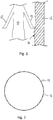
- a caliper tool 10 comprises a plurality of members or fingers 12 that extend radially outwardly from a logging tool. Each finger 12 extends outwardly until it comes into contact with an internal surface 14 of a pipe 16 in which it is located. By determining the angle of the finger 12 with respect to the tool the radius of the pipe 16 at this position can be determined.
- the readings or measurements obtained using the multi-finger caliper can, therefore, be used to determine the internal diameter and internal shape of the conduit or pipe at a given measured depth as the tool moves through the pipe.
- the multi-finger caliper data can also be used to determine the depths of pits and heights of protrusions that may be present in the pipe or conduit.
- Multi-finger calipers have a fixed number of fingers 12, commonly 24, 40, 56, 60 or 80 fingers, with individual caliper data values obtained for each finger 12.
- Each finger 12 can therefore provide an accurate measurement of the dimension of an inside surface of a structure, but at a low resolution around the circumference of the pipe, i.e. only a small proportion of the inside surface is contacted by a finger 12.
- Figure 2 shows contacts points 18 for 24 fingers around an internal circumference of a pipe 16.
- the calliper fingers would cover only 11.15% of the surface of the pipe around its internal circumference.
- radius values for areas of the pipe between the caliper fingers have been established by linear interpolation of neighbouring caliper data values to obtain radius measurements over the complete area of the internal surface of the pipe. This method, however, may fail to identify smaller regions between the caliper fingers that may have a localised increase or decrease in radius compared to the surrounding pipe surface due to pitting/corrosion or deposition respectively.
- Images of the internal surface of a pipe or conduit may be captured using a downview or sideview camera on a logging tool, as is known in the art. Images obtained by downhole camera systems are captured using high resolution sensors, typically resulting in images with in the order of over ten pixels per square millimetre of pipe surface. Subsequent image processing of the captured images, to identify regions of similarity, can be used to identify the location of defects on a pipe surface, or patches of rust, for example. The images, however, provide little or no quantitative information regarding variations in radius of the pipe or changes in the depth of the surface being viewed due to pitting or corrosion for example.
- EP 2813813 A1 discloses measurement of an inner diameter or shape of an inner surface using both a contact measurement and an optical measurement.
- AU 2015 200693 A1 discloses an in-line inspection tool and a method of cross-correlating sensor data to inspect the integrity of pipelines.
- US 2003/0198374 A1 discloses extracting a depth profile from images of the inside surface of a pipeline.
- US 2006/0152589 A2 discloses correcting video frames using sensor data relating to the position of a camera.
- CN 105069751 A discloses a method of in-filling missing depth information in data obtained from a depth image sensor providing a depth image and a corresponding colour image.
- the present invention resides in a method of constructing a three-dimensional model of an internal surface of a downhole tubular structure, comprising:
- the method therefore provides a way to obtain quantitative information about the three-dimensional shape of the internal surface outside those regions from which direct measurements of the shape of the surface have been obtained.
- Correlating the measured height profile data with the image properties may comprise identifying one or more regions of similarity in the image data, at least one of the regions of similarity being at least partly coincident with at least one of the sub-regions.
- the measured height profile data obtained from the or each sub-region can then be correlated with the image properties in the or each coincident region of similarity to obtain a function relating the image properties to the measured height profile data.
- Constructing the expected height profile data may comprise applying the function to the image properties in the corresponding regions of similarity outside the or each sub-region.
- the regions of similarity may be contiguous or may be formed of two or more separate areas in the image.
- the regions of similarity may be determined by image analysis, and may for example be identified based on RGB values, intensity, pattern matching, and so on.
- the regions of similarity may be identified using the original image data, the image properties determined from the image data for correlation with the measured height profile data, or from other image properties derived from the image data.
- Any suitable image properties can be determined from the image data for correlation with the measured height profile data.
- a single type of image property may be determined or two or more different types of image property may be determined.
- determining the image properties from the image data comprises determining image gradients. Determining image gradients may comprise determining, for each of a plurality of pixels of the image, a change in intensity between that pixel and one or more neighbouring pixels.
- the image data comprises a plurality of variant images of the same area
- determining the image properties from the image data comprises determining variations between the plurality of variant images.
- the variant images comprise images of the same area taken at different viewing angles or with different lighting angles or under different lighting conditions.
- determining the image properties from the image data may comprise determining intensity variations between the plurality of variant images.
- the method comprises determining a depth position of the image data and a depth position of the measured height profile data, and correlating the measured height profile data with the image properties comprises matching the depth position of the measured height profile data to the depth position of the image data.
- the method includes obtaining a video stream from a camera tool as the camera tool moves through the structure.
- the image data may be obtained from the video stream.
- the video stream comprises a sequence of images taken at a predetermined frame rate.
- the method may comprise determining an overlap distance between each pair of successive images in the sequence of images, calculating, from the overlap distance and the frame rate, a speed of movement of the camera tool corresponding to each image, and determining, from the speed of movement of the tool, the depth position of the image data corresponding to each image.
- the method may comprise obtaining the measured height profile data from a surface height sensor disposed on or connected to the camera tool, and determining, from the speed of movement of the camera tool, the depth position of the measured height profile data.
- the measured height profile data and the image data may be obtained at substantially the same time (i.e. during the passage of the tool or tool string through an area of interest in the structure).
- the surface height sensor may be disposed on a different tool, in which case the depth position of the measured height profile data may be determined in a different way.
- the measured height profile data may be obtained from a set of calipers.
- the measured height profile data may be obtained using a multi-finger caliper tool.
- the spatial resolution of the expected height profile data is preferably greater than the spatial resolution of the measured height profile data.
- the spatial resolution of the expected height profile data may be substantially equal to the spatial resolution of the image data.
- a method according to the present invention combines image data from video or still images with caliper data from a multi-fingered caliper tool.
- the image data and caliper data is captured within a pipe or conduit and is used to generate a 2D or 3D quantitative model of the internal surface of the pipe or conduit.
- this method will find particular application in the real-time or post-processing of downhole video camera images from surface or subsurface pipes in the oil and gas industry.
- the data assimilated and generated by the method may be used for precision correlation of measured corrosion pitting with observed pitting in camera images.
- the data may be used to identify micro sized pits.
- the method may be used for time lapse monitoring of corrosion / erosion, deposits / obstructions, milling / clean-up, damage / wear / buckling, perforations / sleeve or screen damage.
- the method provides a way of measuring pitting across the entire circumference of the pipe, without being restricted by the limited circumferential coverage of caliper fingers.
- the method comprises obtaining image data from an area of an internal surface of a pipe or conduit, obtaining height profile data from the internal surface in a sub-region of the area, identifying, in the image data, regions of similarity, determining one or more image properties inside the regions of similarity, correlating the height profile data with the image properties inside the regions of similarity, and based on the correlations, using the image properties to construct height profile data outside the sub-region of the surface.
- the method comprises obtaining image data from an area of an internal surface of a pipe or conduit, obtaining height profile data from the internal surface in a sub-region of the area, identifying, in the image data, regions of similarity, and using the height profile data from the sub-region of the area to construct a height profile for the area outside the sub-region based on the regions of similarity.
- the term "height" is used to refer to the deviation of the internal surface of the tubular structure from a regular cylindrical or otherwise smooth surface. For example, a region of the surface that projects towards the centreline of the tubular structure, resulting in a locally decreased radius, can be taken to have a positive height, while a region of the surface that is eroded or pitted, resulting in a locally increased radius, can be taken to have a negative height. It will be appreciated that the height of the surface could instead be expressed simply as a local radius of the structure.
- tubular structure should be construed broadly, and includes substantially any downhole structure having a bore into which a tool could be passed. Examples include wellbores, well casings, boreholes, pipes, conduits and so on, as may be typically used in oil and gas production.
- tubular should likewise be construed broadly, and includes structures having a generally tubular form; such structures may be axially straight or bent, twisted or otherwise deformed, and may have a bore with a non-circular cross-section. The invention is applied to downhole tubular structures.
- the method of the present invention combines images of an internal surface of a pipe or conduit with physical surface height measurement data to obtain a higher resolution 3D model of the internal surface of the structure than that obtainable from the measurement data alone.
- the method therefore comprises obtaining an image of an area of the internal surface of a downhole structure using a downhole logging tool equipped with a camera, and measuring the height profile of the internal surface within sub-regions of the imaged area, for example using a multi-fingered caliper tool of the type shown in Figures 1 and 2 .
- caliper data corresponding to measurements of the internal diameter or radius of the pipe are captured using the multi-finger caliper tool.
- the caliper tool may be located on the same logging tool as the camera or may be disposed on a separate, different logging tool.
- Each finger of the multi-finger caliper tool provides a set of caliper data values that correspond to measurements made as the finger moves longitudinally through the pipe, resulting in a set of angularly-spaced linear strips of measured height profile data.
- the caliper data is then aligned with the image, such that the strips of linear caliper data 20 are effectively overlaid onto the image 22 as illustrated in Figure 3 .
- the method uses image processing techniques to identify parts of the image between the strips that can be expected to correspond in surface height to parts of the image within the strips, so that the physical measurement data can be extrapolated to provide a higher resolution model of the surface height of the structure across the whole image or across a particular segment or region of interest within the image. In this way, a region of the image for which no measurement data is available can be matched to a similar region of the image for which physical measurement data is available, allowing expected height profile data to be calculated using the relationships established during correlation.
- a first step 101 images of the internal surface of a pipe are captured as a downhole logging tool or camera tool moves through the pipe.
- the images are frames of a video stream.
- step 102 the images and related information are processed to produce image data corresponding to an area of the internal surface of the structure.
- overlapping frames of the video can be aligned and stitched together to form a composite image of the area of interest.
- the amount of axial overlap between video frames gives an estimate of the axial movement and speed of the logging tool, allowing for the depth at which each frame was captured to be determined or corrected.
- the video stream consists of a series of images taken at a predetermined frame rate.
- an overlap distance between each pair of successive images can be determined. This comparison can be made using any suitable image analysis technique, as will be familiar to those skilled in the art.
- the speed of movement of the camera tool at the time at which each image in the video stream was captured can then be calculated or estimated from knowledge of the overlap distance and the frame rate.
- the depth position of the image data corresponding to each image can then be determined by integrating the speeds with respect to image capture time.
- the depth position can for example be expressed as a distance from a known point in the structure, such as the top of the structure or an identifying point disposed along the structure.
- the depth position of the image data could be verified or alternatively determined by reference to a depth reading of the logging tool, which may be obtained from surface depth measurements, a timestamped depth encoder, or via onboard accelerometer and gyrometer data, as is known in the art.
- a further processing step that may be included in step 102 is circumferential stitching of the images, to provide image data over an area that exceeds the circumferential angle of view of the camera, preferably around the whole circumference of the structure.
- the processing in step 102 may also include azimuthal alignment of the image data, to correct for the tool (and therefore the camera or cameras) being imperfectly aligned with the vertical or with the axis of the structure.
- the azimuthal alignment of the tool can be determined for example using a "high side" detector of the tool, which indicates the azimuth of the tool that is uppermost at any time, and a suitable correction factor can be applied to the image data.
- the image data may be corrected in step 102 to account for non-concentricity of the tool.
- Step 102 may also involve the application of various image processing techniques such as are known in the art to improve contrast, enhance or correct colours, remove noise, and so on.
- the output of step 102 is a set of corrected and aligned image data relating to an area of the internal surface of the structure at a known position.
- one or more derivative image properties are calculated from the image data. For example, an intensity gradient may be calculated for each pixel in the image by determining the change in intensity between the subject pixel and one or more neighbouring pixels, with each pixel corresponding to a particular location on the internal surface of the structure. The rate of change of intensity gradient could also be calculated in step 103.
- a plurality of sets of image data are available for the same area, for instance as a result of axially overlapping video frames or circumferentially overlapping images from a multiple-camera tool.
- the sets of image data will differ due to the differences in viewing angle from which the area was imaged. It is therefore possible, in step 103, to calculate the difference in image intensity for each location on the internal surface as a result of different viewing angles.
- a plurality of sets of image data are available for the same area in which set of image data has been derived from images taken under different lighting conditions, such as different lighting angles.
- the difference in image intensity is calculated for each location on the internal surface as a result of different lighting angles.
- the image property data is analysed to identify regions of similarity.
- Figure 5 shows an area of the surface of the structure with the position of three strips 20 from which caliper data has been obtained. Regions of similarity 24, 26, 28 have been identified in the image property data. The like-shaded and like-numbered regions are corresponding regions of similarity. Within each region of similarity, and in corresponding regions of similarity, the height of the surface can be expected to be constant or to follow a functional relationship with one or more of the derivative image properties calculated in step 103.
- the regions of similarity may be identified by analysis of the derivative image properties calculated in step 103. Alternatively, or in addition, the regions of similarity may be identified by analysis of other image properties, such as RGB values, intensity/brightness, and so on, or by image analysis techniques.
- a feature of interest spans more than one image, then multiple images may be stitched together using known image processing techniques to determine the full extent of the feature of interest (and hence the corresponding region of similarity) over the surface of the pipe.
- the features of interest may, for example, correspond to corrosion pitting, erosion, deposits, obstructions, milling features, damage, wear, buckling or perforations.
- Processing of the image data to perform depth corrections, alignments and so on in step 102, to calculate image properties in step 103, and/or to determine regions of similarity in step 104 may occur in real time in the logging tool, or the raw images may be stored in a memory of the logging tool and/or transmitted to a remote station for post processing.
- step 201 physical measurements of the local radius of the structure are obtained using a multi-finger caliper tool, for example by performing a caliper survey as known in the art.
- the raw data from the caliper survey is processed to correct for azimuthal alignment, eccentricity of the tool and other factors as is generally known in the art.
- the resulting measured height profile data comprises a plurality of sets of axially-spaced height readings taken along the linear strips 20 of the surface, with each strip being angularly spaced from its neighbours.
- the measured height profile data is aligned with the image data, so that the height profile data can be correctly correlated with the image data. If the caliper tool and camera are mounted on the same logging tool or tool string, then the tool position determined in step 102 by analysis of axially overlapping images can be used to determine the depth position of each of the height profile data points.
- caliper tool is not mounted on the same tool as the camera, independent depth readings from the caliper tool survey can be used to determine the depth position of each of the measured height profile data points.
- the height profile data determined from the caliper measurement is correlated with one or more of the image properties within the regions of similarity that coincide with the strips or sub-regions of the imaged area for which the height profile data is available.
- a measured height profile data point can be matched to the image properties derived for from the image data at the corresponding location.
- a relationship function relating the image properties to the measured height profile data is then determined for each region of similarity.
- expected height profile data is calculated for regions of the imaged area that lie outside the strips or sub-regions. Within each region of similarity, the corresponding relationship function is applied to the image properties for each pixel of the image to output an expected height value. In this way, an expected height value can be obtained that corresponds to each pixel in an area of interest of the image, resulting in the expected height profile data having being substantially higher spatial resolution than the measured height profile data obtained from the caliper survey.
- a 3D model may be created which accurately represents the surface morphology of the internal surface of the pipe over the complete internal area, as shown in Figure 6 .
- the method may be used to construct a quantitative map or model of pitting and other surface defects and their severity across the full area of the surface of the pipe rather than just in the relatively thin longitudinal regions covered by caliper data alone.
- the quantitative area coverage data provided by correlating the results of the image processing with the caliper data provides far more accurate three dimensional data over the surface of a pipe than a traditional linear interpolation of the caliper data would provide. Furthermore, simple linear interpolation may also completely miss small pitting areas which exist between caliper fingers and which are not contacted by the caliper fingers, or pitting areas that have smaller dimensions than the tip of the caliper finger is able to access.
- the visual characteristics of this section of the image can be noted - for instance, the characteristics of the image area relating to the maximum radius or local maxima - and this severity of pitting can be interpolated to cover similar areas adjoining the caliper trace area.
- the images can be processed to account for fluid clarity and uneven or different lighting conditions. Additional processing of the images may be used to identify and remove features corresponding to fluid particulates, that might otherwise be mistaken for features on the surface of the pipe or conduit.
- post processing of an image may need to account for the logging tool not being located centrally in the pipe or conduit when the image was captured. This is required to more accurately determine the circumferential or longitudinal dimensions of a defect or feature, which may otherwise be considered to be smaller than in reality if the camera lens is further from that region of the surface of the pipe or larger if the camera lens is nearer to that region of the surface of the pipe.
- the method allows different relationship functions to be assigned to different regions of similarity, thus improving the accuracy of the expected height profile data. It is however conceivable that the step of identifying regions of similarity could be omitted, and a single relationship function derived between the measured height profile data and the image property data across the whole of the area of interest.
- the method includes determining, for each region of similarity or for the whole area, a plurality of relationship functions, each function relating the measured height profile data to a different image property. The fit of the measured data to each function can be assessed statistically and the "best" function selected for subsequent calculation of the expected height profile data.
- the method of the invention has specific applications when analysing pipes and tubulars for pitting and monitoring the extent of corrosion.
- utilising the information generated from this method can provide more accurate corrosion measurements and can thereby provide a more accurate estimation of metal loss from a pipe, casing or other structure.
- This in turn can be used to provide a more accurate estimation of pressure limitations of the corroded, damaged, worn or otherwise weakened structure.
- the method of the present invention may be used to monitor evolution of corrosion or pitting of a pipe surface over time, by directly comparing image and caliper data collected at specified time points. In this way, specific features of interest may be automatically categorised and detected. With this information, a point cloud can be calculated and used to generate an accurate 3D model of the pipe surface with automatically annotated regions of concern.
- image data may be combined with data obtained from other mechanical or electrical sensors.
- the mechanical or electrical sensors provide quantitative data or measurements relating to a physical property of the pipe surface that is not obtainable through image processing of the captured 2D images of the pipe internal surface, but the mechanical or electrical sensors measure the physical property only over a limited area of the surface of the pipe.
- the image data required can most conveniently be obtained from video data captured as a tool moves through the structure, it will be understood that the image data could instead be derived from one or more still images of the internal surface of the structure.
Landscapes
- Physics & Mathematics (AREA)
- General Physics & Mathematics (AREA)
- Engineering & Computer Science (AREA)
- Computer Vision & Pattern Recognition (AREA)
- Theoretical Computer Science (AREA)
- Length Measuring Devices By Optical Means (AREA)
Claims (14)
- Procédé de construction d'un modèle tridimensionnel d'une surface interne (14) d'une structure tubulaire de fond de trou (16), comprenant :obtenir (101) des données d'image d'une zone de la surface interne (14) de la structure (16) à l'aide d'un outil de caméra de fond de trou ;obtenir (201) des données de profil de hauteur mesuré de la surface interne (14) dans une pluralité de sous-régions (20) de la zone ;déterminer (103) des propriétés d'image à partir des données d'image ;déterminer une position de profondeur des données d'image et une position de profondeur des données de profil de hauteur mesuré ;mettre en corrélation (106) les données de profil de hauteur mesuré avec les propriétés d'image (106) dans les sous-régions (20) ; etconstruire (107) des données de profil de hauteur prévu pour au moins une partie de la zone à l'extérieur des sous-régions (20) à l'aide (a) de la corrélation entre les données de profil de hauteur mesuré et les propriétés d'image dans les sous-régions (20) et (b) les propriétés d'image à l'extérieur des sous-régions (20) ;mettre en corrélation (106) les données de profil de hauteur mesuré avec les propriétés d'image comprenant mettre en correspondance (203) la position de profondeur des données de profil de hauteur mesuré avec la position de profondeur des données d'image.
- Procédé selon la revendication 1, dans lequel mettre en corrélation (106) les données de profil de hauteur mesuré avec les propriétés d'image comprend :identifier (105) une ou plusieurs régions de similarité (24, 26, 28) dans les données d'image, au moins l'une des régions de similarité (24, 26, 28) coïncidant au moins partiellement avec au moins l'une des sous-régions (20) ; etmettre en corrélation (106) les données de profil de hauteur mesuré obtenues de la ou de chaque sous-région (20) avec les propriétés d'image dans la ou dans chaque région de similarité (24, 26, 28) coïncidente pour obtenir une fonction reliant les propriétés d'image aux données de profil de hauteur mesuré.
- Procédé selon la revendication 2, dans lequel construire (107) les données de profil de hauteur prévu comprend appliquer la fonction aux propriétés d'image dans les régions de similarité (24, 26, 28) correspondantes à l'extérieur de la ou de chaque sous-région (20).
- Procédé selon l'une quelconque des revendications précédentes, dans lequel déterminer (103) les propriétés d'image à partir des données d'image comprend déterminer des gradients d'image.
- Procédé selon la revendication 4, dans lequel déterminer des gradients d'image comprend déterminer, pour chacun d'une pluralité de pixels de l'image, un changement dans l'intensité entre ce pixel et un ou plusieurs pixels voisins.
- Procédé selon l'une quelconque des revendications précédentes, dans lequel les données d'image comprennent une pluralité d'images différentes de la même zone, et déterminer (103) les propriétés d'image à partir des données d'image comprenant déterminer des variations entre la pluralité d'images différentes.
- Procédé selon la revendication 6, dans lequel les images différentes comprennent des images de la même zone prises selon différents angles de vue.
- Procédé selon la revendication 6 ou la revendication 7, dans lequel les images différentes comprennent des images de la même zone prises selon différents angles d'éclairage.
- Procédé selon l'une quelconque des revendications 6 à 8, dans lequel déterminer (103) les propriétés d'image à partir des données d'image comprend déterminer des variations d'intensité entre la pluralité d'images différentes.
- Procédé selon l'une quelconque des revendications précédentes, comprenant :obtenir (101) un flux vidéo à partir de l'outil de caméra alors que l'outil de caméra se déplace à travers la structure (16), le flux vidéo comprenant une séquence d'images prises à une fréquence d'image prédéterminée ;déterminer une distance de chevauchement entre chaque paire d'images successives dans la séquence d'images ;calculer, à partir de la distance de chevauchement et de la fréquence d'image, une vitesse de déplacement de l'outil de caméra correspondant à chaque image ; etdéterminer, à partir de la vitesse de déplacement de l'outil, la position de profondeur des données d'image correspondant à chaque image.
- Procédé selon la revendication 10, comprenant :obtenir (201) les données de profil de hauteur mesuré sensiblement en même temps que les données d'image à partir d'un capteur de hauteur de surface disposé sur ou relié à l'outil de caméra ;déterminer, à partir de la vitesse de déplacement de l'outil de caméra, la position de profondeur des données de profil de hauteur mesuré.
- Procédé selon l'une quelconque des revendications précédentes, comprenant obtenir (201) les données de profil de hauteur mesuré à partir d'un ensemble de compas d'épaisseur (12).
- Procédé selon l'une quelconque des revendications précédentes, dans lequel la résolution spatiale des données de profil de hauteur prévu est supérieure à la résolution spatiale des données de profil de hauteur mesuré (20).
- Procédé selon la revendication 13, dans lequel la résolution spatiale des données de profil de hauteur prévu est sensiblement égale à la résolution spatiale des données d'image.
Applications Claiming Priority (2)
| Application Number | Priority Date | Filing Date | Title |
|---|---|---|---|
| GBGB1712486.8A GB201712486D0 (en) | 2017-08-03 | 2017-08-03 | Quantative surface measurements by combining image and height profile data |
| PCT/GB2018/052226 WO2019025812A1 (fr) | 2017-08-03 | 2018-08-03 | Mesures quantitatives de surface par la combinaison de données d'image et de données de profil de hauteur |
Publications (2)
| Publication Number | Publication Date |
|---|---|
| EP3461282A1 EP3461282A1 (fr) | 2019-04-03 |
| EP3461282B1 true EP3461282B1 (fr) | 2021-11-03 |
Family
ID=59894759
Family Applications (1)
| Application Number | Title | Priority Date | Filing Date |
|---|---|---|---|
| EP18758672.2A Active EP3461282B1 (fr) | 2017-08-03 | 2018-08-03 | Mesures quantitatives de surface par la combinaison de données d'image et de données de profil de hauteur |
Country Status (6)
| Country | Link |
|---|---|
| US (1) | US10885649B2 (fr) |
| EP (1) | EP3461282B1 (fr) |
| CA (1) | CA3027904C (fr) |
| DK (1) | DK3461282T3 (fr) |
| GB (1) | GB201712486D0 (fr) |
| WO (1) | WO2019025812A1 (fr) |
Families Citing this family (5)
| Publication number | Priority date | Publication date | Assignee | Title |
|---|---|---|---|---|
| GB201802808D0 (en) * | 2018-02-21 | 2018-04-04 | Ev Offshore Ltd | Depth and speed correction of logging data |
| US11261729B2 (en) * | 2019-06-03 | 2022-03-01 | Schlumberger Technology Corporation | Methods and systems for determining integrity and operational boundaries of subterranean wells |
| US11579586B2 (en) * | 2019-09-30 | 2023-02-14 | Saudi Arabian Oil Company | Robot dispatch and remediation of localized metal loss following estimation across piping structures |
| EP4321837A1 (fr) * | 2022-08-10 | 2024-02-14 | Nexans | Procédé pour déterminer la qualité d'une surface de câble |
| CN116186864B (zh) * | 2023-04-24 | 2023-07-07 | 中南冶勘资源环境工程有限公司 | 一种基于bim技术的深基坑模型快速建模方法及系统 |
Citations (1)
| Publication number | Priority date | Publication date | Assignee | Title |
|---|---|---|---|---|
| CN105069751A (zh) * | 2015-07-17 | 2015-11-18 | 江西欧酷智能科技有限公司 | 一种深度图像缺失数据的插值方法 |
Family Cites Families (7)
| Publication number | Priority date | Publication date | Assignee | Title |
|---|---|---|---|---|
| US6931149B2 (en) | 2002-04-19 | 2005-08-16 | Norsk Elektro Optikk A/S | Pipeline internal inspection device and method |
| GB0222211D0 (en) | 2002-09-25 | 2002-10-30 | Fortkey Ltd | Imaging and measurement system |
| WO2007139187A1 (fr) * | 2006-05-31 | 2007-12-06 | National University Corporation Chiba University | Dispositif de formation d'une image en trois dimensions, procédé de formation d'une image en trois dimensions et programme |
| AU2015200693A1 (en) * | 2008-06-27 | 2015-03-05 | Pii (Canada) Limited | Integrated multi-sensor non-destructive testing |
| US20120257042A1 (en) * | 2011-04-08 | 2012-10-11 | Fer-Pal Construction Ltd | System for scanning, mapping and measuring conduits |
| WO2013118912A1 (fr) * | 2012-02-09 | 2013-08-15 | 株式会社Ihi | Dispositif de mesure de diamètre intérieur |
| US10009526B2 (en) * | 2014-02-13 | 2018-06-26 | Ut-Battelle, Llc | Apparatus and methods for imaging interior surfaces of a tube or the like |
-
2017
- 2017-08-03 GB GBGB1712486.8A patent/GB201712486D0/en not_active Ceased
-
2018
- 2018-08-03 US US16/307,694 patent/US10885649B2/en active Active
- 2018-08-03 WO PCT/GB2018/052226 patent/WO2019025812A1/fr not_active Ceased
- 2018-08-03 EP EP18758672.2A patent/EP3461282B1/fr active Active
- 2018-08-03 CA CA3027904A patent/CA3027904C/fr active Active
- 2018-08-03 DK DK18758672.2T patent/DK3461282T3/da active
Patent Citations (1)
| Publication number | Priority date | Publication date | Assignee | Title |
|---|---|---|---|---|
| CN105069751A (zh) * | 2015-07-17 | 2015-11-18 | 江西欧酷智能科技有限公司 | 一种深度图像缺失数据的插值方法 |
Also Published As
| Publication number | Publication date |
|---|---|
| CA3027904C (fr) | 2021-11-02 |
| US10885649B2 (en) | 2021-01-05 |
| CA3027904A1 (fr) | 2019-02-03 |
| DK3461282T3 (da) | 2022-01-24 |
| WO2019025812A1 (fr) | 2019-02-07 |
| GB201712486D0 (en) | 2017-09-20 |
| US20200302625A1 (en) | 2020-09-24 |
| EP3461282A1 (fr) | 2019-04-03 |
Similar Documents
| Publication | Publication Date | Title |
|---|---|---|
| EP3461282B1 (fr) | Mesures quantitatives de surface par la combinaison de données d'image et de données de profil de hauteur | |
| US11989832B2 (en) | Method for constructing a 3D representation of a conduit internal surface | |
| EP3514525B1 (fr) | Système interactif semi-automatique d'analyse video de borescope et d'évaluation de dommages et procédé d'utilisation | |
| US10930013B2 (en) | Method and system for calibrating imaging system | |
| US11828157B2 (en) | Image correction methods for downhole inspection tools | |
| NO345693B1 (en) | Pipe damage assessment system and method | |
| CN120525867B (zh) | 基于机器视觉的边坡锚杆钻孔平台施工质量智能检测系统 | |
| EP3755880B1 (fr) | Estimation de la vitesse et de la profondeur d'un outil d'inspection | |
| CN118817694B (zh) | 基于双鱼眼镜头的管道内部检测系统 | |
| Zhang et al. | Structure-from-motion based image unwrapping and stitching for small bore pipe inspections | |
| CN109767426B (zh) | 一种基于图像特征识别的盾构隧道渗漏水检测方法 | |
| CN115234845A (zh) | 基于投影模型的油气管道内壁缺陷图像可视化检测方法 | |
| Li et al. | Bolt loosening angle measurement along full range of screw exposure length based on 3D point cloud | |
| Drews Jr et al. | Tracking system for underwater inspection using computer vision | |
| KR101357810B1 (ko) | 관내 점검을 위한 캡슐형 점검시스템 | |
| CN107111873A (zh) | 用于检测轮胎中的条纹的方法 | |
| JP2019074389A (ja) | 配管検査装置 | |
| CN116012312B (zh) | 一种基于射孔图像的射孔参数的确定方法 | |
| JP6932614B2 (ja) | 亀裂連続性判定システム、判定方法及び判定プログラム、並びに、亀裂検出装置、検出方法及び検出プログラム | |
| Al Shafian et al. | Deep learning enhanced crack detection for tunnel inspection | |
| Esquivel et al. | Reconstruction of sewer shaft profiles from fisheye-lens camera images | |
| Sterckx et al. | Segmentation and Quantification of Surface Defects in 3D Reconstructions for Damage Assessment and Inspection | |
| CN113358058B (zh) | 基于离散序列点的焊缝轮廓特征计算机视觉检测方法 | |
| TWI915234B (zh) | 型鋼的彎直度檢測方法 | |
| KR102536981B1 (ko) | 이동거리 측정 시스템 |
Legal Events
| Date | Code | Title | Description |
|---|---|---|---|
| STAA | Information on the status of an ep patent application or granted ep patent |
Free format text: STATUS: UNKNOWN |
|
| STAA | Information on the status of an ep patent application or granted ep patent |
Free format text: STATUS: THE INTERNATIONAL PUBLICATION HAS BEEN MADE |
|
| PUAI | Public reference made under article 153(3) epc to a published international application that has entered the european phase |
Free format text: ORIGINAL CODE: 0009012 |
|
| STAA | Information on the status of an ep patent application or granted ep patent |
Free format text: STATUS: REQUEST FOR EXAMINATION WAS MADE |
|
| 17P | Request for examination filed |
Effective date: 20181126 |
|
| AK | Designated contracting states |
Kind code of ref document: A1 Designated state(s): AL AT BE BG CH CY CZ DE DK EE ES FI FR GB GR HR HU IE IS IT LI LT LU LV MC MK MT NL NO PL PT RO RS SE SI SK SM TR |
|
| AX | Request for extension of the european patent |
Extension state: BA ME |
|
| REG | Reference to a national code |
Ref country code: DE Ref legal event code: R079 Ref document number: 602018026126 Country of ref document: DE Free format text: PREVIOUS MAIN CLASS: G01B0005280000 Ipc: G01B0005120000 |
|
| RIC1 | Information provided on ipc code assigned before grant |
Ipc: G01B 11/24 20060101ALI20190829BHEP Ipc: G01B 7/34 20060101ALI20190829BHEP Ipc: G01B 5/12 20060101AFI20190829BHEP Ipc: G01B 5/20 20060101ALI20190829BHEP Ipc: F16L 101/30 20060101ALI20190829BHEP Ipc: G01B 11/30 20060101ALI20190829BHEP Ipc: G01B 5/28 20060101ALI20190829BHEP |
|
| STAA | Information on the status of an ep patent application or granted ep patent |
Free format text: STATUS: EXAMINATION IS IN PROGRESS |
|
| 17Q | First examination report despatched |
Effective date: 20191028 |
|
| DAV | Request for validation of the european patent (deleted) | ||
| DAX | Request for extension of the european patent (deleted) | ||
| GRAP | Despatch of communication of intention to grant a patent |
Free format text: ORIGINAL CODE: EPIDOSNIGR1 |
|
| STAA | Information on the status of an ep patent application or granted ep patent |
Free format text: STATUS: GRANT OF PATENT IS INTENDED |
|
| INTG | Intention to grant announced |
Effective date: 20210624 |
|
| GRAS | Grant fee paid |
Free format text: ORIGINAL CODE: EPIDOSNIGR3 |
|
| GRAA | (expected) grant |
Free format text: ORIGINAL CODE: 0009210 |
|
| STAA | Information on the status of an ep patent application or granted ep patent |
Free format text: STATUS: THE PATENT HAS BEEN GRANTED |
|
| AK | Designated contracting states |
Kind code of ref document: B1 Designated state(s): AL AT BE BG CH CY CZ DE DK EE ES FI FR GB GR HR HU IE IS IT LI LT LU LV MC MK MT NL NO PL PT RO RS SE SI SK SM TR |
|
| REG | Reference to a national code |
Ref country code: GB Ref legal event code: FG4D |
|
| REG | Reference to a national code |
Ref country code: AT Ref legal event code: REF Ref document number: 1444330 Country of ref document: AT Kind code of ref document: T Effective date: 20211115 Ref country code: CH Ref legal event code: EP |
|
| REG | Reference to a national code |
Ref country code: IE Ref legal event code: FG4D |
|
| REG | Reference to a national code |
Ref country code: DE Ref legal event code: R096 Ref document number: 602018026126 Country of ref document: DE |
|
| REG | Reference to a national code |
Ref country code: DK Ref legal event code: T3 Effective date: 20220120 |
|
| REG | Reference to a national code |
Ref country code: NO Ref legal event code: T2 Effective date: 20211103 |
|
| REG | Reference to a national code |
Ref country code: NL Ref legal event code: FP |
|
| REG | Reference to a national code |
Ref country code: LT Ref legal event code: MG9D |
|
| REG | Reference to a national code |
Ref country code: AT Ref legal event code: MK05 Ref document number: 1444330 Country of ref document: AT Kind code of ref document: T Effective date: 20211103 |
|
| PG25 | Lapsed in a contracting state [announced via postgrant information from national office to epo] |
Ref country code: RS Free format text: LAPSE BECAUSE OF FAILURE TO SUBMIT A TRANSLATION OF THE DESCRIPTION OR TO PAY THE FEE WITHIN THE PRESCRIBED TIME-LIMIT Effective date: 20211103 Ref country code: LT Free format text: LAPSE BECAUSE OF FAILURE TO SUBMIT A TRANSLATION OF THE DESCRIPTION OR TO PAY THE FEE WITHIN THE PRESCRIBED TIME-LIMIT Effective date: 20211103 Ref country code: FI Free format text: LAPSE BECAUSE OF FAILURE TO SUBMIT A TRANSLATION OF THE DESCRIPTION OR TO PAY THE FEE WITHIN THE PRESCRIBED TIME-LIMIT Effective date: 20211103 Ref country code: BG Free format text: LAPSE BECAUSE OF FAILURE TO SUBMIT A TRANSLATION OF THE DESCRIPTION OR TO PAY THE FEE WITHIN THE PRESCRIBED TIME-LIMIT Effective date: 20220203 Ref country code: AT Free format text: LAPSE BECAUSE OF FAILURE TO SUBMIT A TRANSLATION OF THE DESCRIPTION OR TO PAY THE FEE WITHIN THE PRESCRIBED TIME-LIMIT Effective date: 20211103 |
|
| PG25 | Lapsed in a contracting state [announced via postgrant information from national office to epo] |
Ref country code: IS Free format text: LAPSE BECAUSE OF FAILURE TO SUBMIT A TRANSLATION OF THE DESCRIPTION OR TO PAY THE FEE WITHIN THE PRESCRIBED TIME-LIMIT Effective date: 20220303 Ref country code: SE Free format text: LAPSE BECAUSE OF FAILURE TO SUBMIT A TRANSLATION OF THE DESCRIPTION OR TO PAY THE FEE WITHIN THE PRESCRIBED TIME-LIMIT Effective date: 20211103 Ref country code: PT Free format text: LAPSE BECAUSE OF FAILURE TO SUBMIT A TRANSLATION OF THE DESCRIPTION OR TO PAY THE FEE WITHIN THE PRESCRIBED TIME-LIMIT Effective date: 20220303 Ref country code: PL Free format text: LAPSE BECAUSE OF FAILURE TO SUBMIT A TRANSLATION OF THE DESCRIPTION OR TO PAY THE FEE WITHIN THE PRESCRIBED TIME-LIMIT Effective date: 20211103 Ref country code: LV Free format text: LAPSE BECAUSE OF FAILURE TO SUBMIT A TRANSLATION OF THE DESCRIPTION OR TO PAY THE FEE WITHIN THE PRESCRIBED TIME-LIMIT Effective date: 20211103 Ref country code: HR Free format text: LAPSE BECAUSE OF FAILURE TO SUBMIT A TRANSLATION OF THE DESCRIPTION OR TO PAY THE FEE WITHIN THE PRESCRIBED TIME-LIMIT Effective date: 20211103 Ref country code: GR Free format text: LAPSE BECAUSE OF FAILURE TO SUBMIT A TRANSLATION OF THE DESCRIPTION OR TO PAY THE FEE WITHIN THE PRESCRIBED TIME-LIMIT Effective date: 20220204 Ref country code: ES Free format text: LAPSE BECAUSE OF FAILURE TO SUBMIT A TRANSLATION OF THE DESCRIPTION OR TO PAY THE FEE WITHIN THE PRESCRIBED TIME-LIMIT Effective date: 20211103 |
|
| PG25 | Lapsed in a contracting state [announced via postgrant information from national office to epo] |
Ref country code: SM Free format text: LAPSE BECAUSE OF FAILURE TO SUBMIT A TRANSLATION OF THE DESCRIPTION OR TO PAY THE FEE WITHIN THE PRESCRIBED TIME-LIMIT Effective date: 20211103 Ref country code: SK Free format text: LAPSE BECAUSE OF FAILURE TO SUBMIT A TRANSLATION OF THE DESCRIPTION OR TO PAY THE FEE WITHIN THE PRESCRIBED TIME-LIMIT Effective date: 20211103 Ref country code: RO Free format text: LAPSE BECAUSE OF FAILURE TO SUBMIT A TRANSLATION OF THE DESCRIPTION OR TO PAY THE FEE WITHIN THE PRESCRIBED TIME-LIMIT Effective date: 20211103 Ref country code: EE Free format text: LAPSE BECAUSE OF FAILURE TO SUBMIT A TRANSLATION OF THE DESCRIPTION OR TO PAY THE FEE WITHIN THE PRESCRIBED TIME-LIMIT Effective date: 20211103 Ref country code: CZ Free format text: LAPSE BECAUSE OF FAILURE TO SUBMIT A TRANSLATION OF THE DESCRIPTION OR TO PAY THE FEE WITHIN THE PRESCRIBED TIME-LIMIT Effective date: 20211103 |
|
| REG | Reference to a national code |
Ref country code: DE Ref legal event code: R097 Ref document number: 602018026126 Country of ref document: DE |
|
| PLBE | No opposition filed within time limit |
Free format text: ORIGINAL CODE: 0009261 |
|
| STAA | Information on the status of an ep patent application or granted ep patent |
Free format text: STATUS: NO OPPOSITION FILED WITHIN TIME LIMIT |
|
| 26N | No opposition filed |
Effective date: 20220804 |
|
| PG25 | Lapsed in a contracting state [announced via postgrant information from national office to epo] |
Ref country code: AL Free format text: LAPSE BECAUSE OF FAILURE TO SUBMIT A TRANSLATION OF THE DESCRIPTION OR TO PAY THE FEE WITHIN THE PRESCRIBED TIME-LIMIT Effective date: 20211103 |
|
| PG25 | Lapsed in a contracting state [announced via postgrant information from national office to epo] |
Ref country code: SI Free format text: LAPSE BECAUSE OF FAILURE TO SUBMIT A TRANSLATION OF THE DESCRIPTION OR TO PAY THE FEE WITHIN THE PRESCRIBED TIME-LIMIT Effective date: 20211103 |
|
| PG25 | Lapsed in a contracting state [announced via postgrant information from national office to epo] |
Ref country code: MC Free format text: LAPSE BECAUSE OF FAILURE TO SUBMIT A TRANSLATION OF THE DESCRIPTION OR TO PAY THE FEE WITHIN THE PRESCRIBED TIME-LIMIT Effective date: 20211103 |
|
| REG | Reference to a national code |
Ref country code: CH Ref legal event code: PL |
|
| PG25 | Lapsed in a contracting state [announced via postgrant information from national office to epo] |
Ref country code: LU Free format text: LAPSE BECAUSE OF NON-PAYMENT OF DUE FEES Effective date: 20220803 Ref country code: LI Free format text: LAPSE BECAUSE OF NON-PAYMENT OF DUE FEES Effective date: 20220831 Ref country code: CH Free format text: LAPSE BECAUSE OF NON-PAYMENT OF DUE FEES Effective date: 20220831 |
|
| REG | Reference to a national code |
Ref country code: BE Ref legal event code: MM Effective date: 20220831 |
|
| PG25 | Lapsed in a contracting state [announced via postgrant information from national office to epo] |
Ref country code: IT Free format text: LAPSE BECAUSE OF FAILURE TO SUBMIT A TRANSLATION OF THE DESCRIPTION OR TO PAY THE FEE WITHIN THE PRESCRIBED TIME-LIMIT Effective date: 20211103 |
|
| PG25 | Lapsed in a contracting state [announced via postgrant information from national office to epo] |
Ref country code: IE Free format text: LAPSE BECAUSE OF NON-PAYMENT OF DUE FEES Effective date: 20220803 |
|
| PG25 | Lapsed in a contracting state [announced via postgrant information from national office to epo] |
Ref country code: BE Free format text: LAPSE BECAUSE OF NON-PAYMENT OF DUE FEES Effective date: 20220831 |
|
| PG25 | Lapsed in a contracting state [announced via postgrant information from national office to epo] |
Ref country code: HU Free format text: LAPSE BECAUSE OF FAILURE TO SUBMIT A TRANSLATION OF THE DESCRIPTION OR TO PAY THE FEE WITHIN THE PRESCRIBED TIME-LIMIT; INVALID AB INITIO Effective date: 20180803 |
|
| PG25 | Lapsed in a contracting state [announced via postgrant information from national office to epo] |
Ref country code: MK Free format text: LAPSE BECAUSE OF FAILURE TO SUBMIT A TRANSLATION OF THE DESCRIPTION OR TO PAY THE FEE WITHIN THE PRESCRIBED TIME-LIMIT Effective date: 20211103 Ref country code: CY Free format text: LAPSE BECAUSE OF FAILURE TO SUBMIT A TRANSLATION OF THE DESCRIPTION OR TO PAY THE FEE WITHIN THE PRESCRIBED TIME-LIMIT Effective date: 20211103 |
|
| PG25 | Lapsed in a contracting state [announced via postgrant information from national office to epo] |
Ref country code: TR Free format text: LAPSE BECAUSE OF FAILURE TO SUBMIT A TRANSLATION OF THE DESCRIPTION OR TO PAY THE FEE WITHIN THE PRESCRIBED TIME-LIMIT Effective date: 20211103 |
|
| PG25 | Lapsed in a contracting state [announced via postgrant information from national office to epo] |
Ref country code: MT Free format text: LAPSE BECAUSE OF FAILURE TO SUBMIT A TRANSLATION OF THE DESCRIPTION OR TO PAY THE FEE WITHIN THE PRESCRIBED TIME-LIMIT Effective date: 20211103 |
|
| PGFP | Annual fee paid to national office [announced via postgrant information from national office to epo] |
Ref country code: NL Payment date: 20250821 Year of fee payment: 8 |
|
| PGFP | Annual fee paid to national office [announced via postgrant information from national office to epo] |
Ref country code: DK Payment date: 20250815 Year of fee payment: 8 |
|
| PGFP | Annual fee paid to national office [announced via postgrant information from national office to epo] |
Ref country code: NO Payment date: 20250819 Year of fee payment: 8 |
|
| PGFP | Annual fee paid to national office [announced via postgrant information from national office to epo] |
Ref country code: GB Payment date: 20250801 Year of fee payment: 8 |
|
| PGFP | Annual fee paid to national office [announced via postgrant information from national office to epo] |
Ref country code: FR Payment date: 20250819 Year of fee payment: 8 |
|
| PGFP | Annual fee paid to national office [announced via postgrant information from national office to epo] |
Ref country code: DE Payment date: 20250925 Year of fee payment: 8 |