EP3461433A2 - Kreisförmiges klammerinstrument mit asymmetrischen geformten abdeckungskomponenten - Google Patents
Kreisförmiges klammerinstrument mit asymmetrischen geformten abdeckungskomponenten Download PDFInfo
- Publication number
- EP3461433A2 EP3461433A2 EP18196953.6A EP18196953A EP3461433A2 EP 3461433 A2 EP3461433 A2 EP 3461433A2 EP 18196953 A EP18196953 A EP 18196953A EP 3461433 A2 EP3461433 A2 EP 3461433A2
- Authority
- EP
- European Patent Office
- Prior art keywords
- anvil
- assembly
- section
- shaft portion
- handle portion
- Prior art date
- Legal status (The legal status is an assumption and is not a legal conclusion. Google has not performed a legal analysis and makes no representation as to the accuracy of the status listed.)
- Granted
Links
Images


Classifications
-
- A—HUMAN NECESSITIES
- A61—MEDICAL OR VETERINARY SCIENCE; HYGIENE
- A61B—DIAGNOSIS; SURGERY; IDENTIFICATION
- A61B17/00—Surgical instruments, devices or methods
- A61B17/11—Surgical instruments, devices or methods for performing anastomosis; Buttons for anastomosis
- A61B17/115—Staplers for performing anastomosis, e.g. in a single operation
- A61B17/1155—Circular staplers comprising a plurality of staples
-
- A—HUMAN NECESSITIES
- A61—MEDICAL OR VETERINARY SCIENCE; HYGIENE
- A61B—DIAGNOSIS; SURGERY; IDENTIFICATION
- A61B17/00—Surgical instruments, devices or methods
- A61B17/11—Surgical instruments, devices or methods for performing anastomosis; Buttons for anastomosis
- A61B17/1114—Surgical instruments, devices or methods for performing anastomosis; Buttons for anastomosis of the digestive tract, e.g. bowels or oesophagus
-
- A—HUMAN NECESSITIES
- A61—MEDICAL OR VETERINARY SCIENCE; HYGIENE
- A61B—DIAGNOSIS; SURGERY; IDENTIFICATION
- A61B17/00—Surgical instruments, devices or methods
- A61B2017/00367—Details of actuation of instruments, e.g. relations between pushing buttons, or the like, and activation of the tool, working tip, or the like
-
- A—HUMAN NECESSITIES
- A61—MEDICAL OR VETERINARY SCIENCE; HYGIENE
- A61B—DIAGNOSIS; SURGERY; IDENTIFICATION
- A61B17/00—Surgical instruments, devices or methods
- A61B2017/00477—Coupling
-
- A—HUMAN NECESSITIES
- A61—MEDICAL OR VETERINARY SCIENCE; HYGIENE
- A61B—DIAGNOSIS; SURGERY; IDENTIFICATION
- A61B90/00—Instruments, implements or accessories specially adapted for surgery or diagnosis and not covered by any of the groups A61B1/00 - A61B50/00, e.g. for luxation treatment or for protecting wound edges
- A61B90/08—Accessories or related features not otherwise provided for
- A61B2090/0807—Indication means
- A61B2090/0811—Indication means for the position of a particular part of an instrument with respect to the rest of the instrument, e.g. position of the anvil of a stapling instrument
Definitions
- instrument (10) comprises a closure system and a firing system.
- closure system and anvil (40) are operable to clamp tissue between anvil (40) and stapling head assembly (200).
- firing system and anvil (40) are operable to cut and staple tissue clamped between anvil (40) and stapling head assembly (200).
- the closure system comprises a trocar (230), a trocar actuator (231), and an adjustment knob (98).
- Anvil (40) may be coupled to a distal end of trocar (230).
- Adjustment knob (98) is operable to longitudinally translate trocar (230) relative to stapling head assembly (200), thereby translating anvil (40) when anvil (40) is suitably coupled to trocar (230), and further clamping tissue between anvil (40) and stapling head assembly (200) as will be described in greater detail below.
- the firing system comprises a trigger (74), a trigger actuation assembly (84), a driver actuator (64), and a staple driver member (250).
- Staple driver member (250) includes a knife member (240) configured to sever tissue when staple driver member (250) is actuated longitudinally.
- staples (66) are positioned distal to a plurality of staple drivers of staple driver member (250) such that staple driver member (250) also drives staples (66) distally when staple driver member (250) is actuated longitudinally.
- trigger actuation assembly (84) actuates staple driver member (250) via driver actuator (64), knife member (240) and staple drivers (252) substantially simultaneously sever tissue (2) and drive staples (66) distally relative to stapling head assembly (200) into tissue.
- distal and proximal will be used with reference to the orientation of anvil (40) when anvil (40) is coupled with shaft assembly (60) of instrument (10).
- proximal features of anvil (40) will be closer to the operator of instrument (10); while distal features of anvil (40) will be further from the operator of instrument (10).
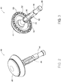
- anvil (40) of the present example comprises a head (48) and a proximal shaft (44).
- anvil (40) of the present example may selectively couple to trocar (230) such that when coupled, movement of trocar (230) relative to stapling head assembly (200) also moves anvil (40) relative to stapling head assembly (200).
- Head (48) includes a proximal surface (50) that defines a plurality of staple forming pockets (52).
- Staple forming pockets (52) are arranged in two concentric annular arrays.
- staple forming pockets (52) are arranged in three or more concentric annular arrays.
- Staple forming pockets (52) are configured to deform staples as the staples are driven into staple forming pockets (52). Accordingly, when anvil (40) is in the closed position and staples (66) are driven out of stapling head assembly (200) into staple forming pockets (52), each staple forming pocket (52) may deform a generally "U” shaped staple (66) into a "B" shape as is known in the art.
- proximal surface (50) terminates at an inner edge (54), which defines an outer boundary of an annular recess (56) surrounding proximal shaft (44).
- Lateral openings (42) thus provide clearance for distal ends (34) and latch shelves (36) to deflect radially outwardly from the longitudinal axis defined by proximal shaft (44).
- latch members (30) are configured to resiliently bias distal ends (34) and latch shelves (36) radially inwardly toward the longitudinal axis defined by proximal shaft (44).
- Latch members (30) thus act as retaining clip to allow anvil (40) to be selectively secured to trocar (230) of stapling head assembly (200). It should be understood, however, that latch members (36) are merely optional.
- Anvil (40) maybe removably secured to a trocar (230) using any other suitable components, features, or techniques.
- stapling head assembly (200) of the present example is coupled to a distal end of shaft assembly (60) and comprises a tubular casing (210) housing a slidable staple driver member (250).
- a cylindraceous inner core member extends distally within tubular casing (210).
- Tubular casing (210) is fixedly secured to an outer sheath (62) of shaft assembly (60), such that tubular casing (210) serves as a mechanical ground for stapling head assembly (200).
- Trocar (230) is positioned coaxially within inner core member (212) of tubular casing (210). As mentioned above and as will be described in greater detail below, trocar (230) is operable to translate distally and proximally relative to tubular casing (210) in response to rotation of adjustment knob (98) relative to casing (110) of handle assembly (100).
- Trocar (230) comprises a shaft (232) and a head (234). Head (234) includes a pointed tip (236) and an inwardly extending proximal surface (238). Shaft (232) thus provides a reduced outer diameter just proximal to head (234), with surface (238) providing a transition between that reduced outer diameter of shaft (232) and the outer diameter of head (234).
- Knife member (240) is coaxially positioned within staple driver member (250).
- Knife member (240) includes a distally presented, sharp circular cutting edge (242).
- Knife member (240) is sized such that knife member (240) defines an outer diameter that is smaller than the diameter defined by the inner annular array of staple drivers (252).
- Knife member (240) also defines an opening that is configured to coaxially receive core member (212) of tubular casing (210).
- An annular array of openings (246) formed in knife member (240) is configured to complement the annular array of studs (256) of staple driver member (250), such that knife member (240) is fixedly secured to staple driver member (250) via studs (256) and openings (346).
- knife member (240) when stapling driver member (250) is actuated relative to tubular casing (210), so is knife member (240).
- Other suitable structural relationships between knife member (240) and stapler driver member (250) will be apparent to those of ordinary skill in the art in view of the teachings herein.
- a deck member (220) is fixedly secured to tubular casing (210).
- Deck member (220) includes a distally presented deck surface (222) defining two concentric annular arrays of staple openings (224), where each staple opening (224) has its own staple pocket (226) housing a staple (66).
- Staple openings (224) and staple pockets (226) are arranged to correspond with the arrangement of staple drivers (252) and staple forming pockets (52) described above. Accordingly, when staple driver member (250) is actuated distally relative to tubular casing (210) in response to rotation of trigger (74), each staple driver (252) drives a corresponding staple (66) out of its staple pocket (226) and through a corresponding staple opening (224) of deck member (220).
- staples (66) are driven into a corresponding staple forming pockets (52) to bend legs (68) of the staples (66), thereby stapling the material located between anvil (40) and stapling head assembly (200).
- the arrangement of staple openings (224) may be modified just like the arrangement of staple forming pockets (52) as described above. It should also be understood that various structures and techniques may be used to contain staples (66) within stapling head assembly (200) before stapling head assembly (200) is actuated. Such structures and techniques that are used to contain staples within stapling head assembly (200) may prevent the staples from inadvertently falling out through staple openings (224) before stapling head assembly (200) is actuated. Various suitable forms that such structures and techniques may take will be apparent to those of ordinary skill in the art in view of the teachings herein.
- deck member (220) defines an inner diameter that is just slightly larger than the outer diameter defined by knife member (240). Deck member (220) is thus configured to allow knife member (240) to translate distally to a point where cutting edge (242) is distal to deck surface (222).
- stapling head assembly (200) may be further constructed and operable in accordance with at least some of the teachings of U.S. Pat. No. 5,205,459 ; U.S. Pat. No. 5,271,544 ; U.S. Pat. No. 5,275,322 ; U.S. Pat. No. 5,285,945 ; U.S. Pat. No. 5,292,053 ; U.S. Pat. No. 5,333,773 ; U.S. Pat. No. 5,350,104 ; U.S. Pat. No. 5,533,661 ; U.S. Pat. No. 8,910,847 ; U.S. Pub.
- Stapling head assembly (200) and trocar (230) are positioned at a distal end of shaft assembly (60), as shown in FIGS. 10A-10D .
- Shaft assembly (60) of the present example comprises an outer tubular member (62) and a driver actuator (64). Outer tubular member (62) is coupled to tubular casing (210) of stapling head assembly (200) and to a body (72) of actuator handle assembly (70), thereby providing a mechanical ground for the actuating components therein.
- the proximal end of driver actuator (64) is coupled to a trigger actuation assembly (84) of actuator handle assembly (70), as described below.
- driver actuator (64) is coupled to staple driver member (250) such that the rotation of trigger (74) longitudinally actuates staple driver member (250).
- driver actuator (64) comprises a tubular member having an open longitudinal axis such that trocar actuator (231), which is coupled to trocar (230), may actuate longitudinally within and relative to driver actuator (64).
- Other components may be disposed within driver actuator (64) as will be apparent to one of ordinary skill in the art in view of the teachings herein.
- shaft assembly (60) is substantially straight. However, shaft assembly (60) may extend distally from actuator handle assembly (70) with a preformed bend. In some versions, the preformed bend is configured to facilitate positioning of stapling head assembly (200) within a patient's colon. Various suitable bend angles or radii that may be used will be apparent to those of ordinary skill in the art in view of the teachings herein.
- actuator (231) may be coupled with trocar (230) via a flexible band portion (not shown). Flexible band portion (not shown) may extend from a distal end of actuator (231), located proximal to the preformed bend, to couple with trocar (230), located distal to the preformed bend.
- Flexible band portion may be dimensioned to flex during translation along the longitudinal profile of the preformed bend of shaft assembly (60).
- trocar actuator (231) may be slidably housed within actuator handle assembly (70), while trocar (230) is slidably housed within tubular casing (210).
- Flexible band portion (not shown) may be connected to both trocar (230) and actuator (231) via pins.
- Shaft assembly (60) may be further constructed in accordance with at least some of the teachings of U.S. Pat. No. 5,205,459 ; U.S. Pat. No. 5,271,544 ; U.S. Pat. No. 5,275,322 ; U.S. Pat. No. 5,285,945 ; U.S. Pat. No. 5,292,053 ; U.S. Pat. No. 5,333,773 ; U.S. Pat. No. 5,350,104 ; U.S. Pat. No. 5,533,661 ; U.S. Pub. No. 2012/0292372 ; and/or U.S. Pub. No. 2015/0083773 , the disclosures of which are incorporated by reference herein; and/or in accordance with other configurations as will be apparent to one of ordinary skill in the art in view of the teachings herein.
- actuator handle assembly (70) comprises a body (72), a trigger (74), a lockout feature (82), a trigger actuation assembly (84), and a trocar actuation assembly (90).
- Trigger (74) of the present example is pivotably mounted to body (72) and is coupled to trigger actuation assembly (84) such that rotation of trigger (74) from an unfired position (shown in FIG. 7A ) to a fired position (shown in FIG. 7B ) actuates driver actuator (64) described above.
- a spring (78) is coupled to body (72) and trigger (74) to bias trigger (74) towards the unfired position.
- Lockout feature (82) is a pivotable member that is coupled to body (72).
- lockout feature (82) In a first, locked position, as shown in FIG. 7A , lockout feature (82) is pivoted upwards and away from body (72) such that lockout feature (82) engages trigger (74) and mechanically resists actuation of trigger (74) by a user. In a second, unlocked position, such as that shown in FIGS. 1 and 7B , lockout feature (82) is pivoted downward such that trigger (74) may be actuated by the user. Accordingly, with lockout feature (82) in the second position, trigger (74) can engage a trigger actuation assembly (84) to fire instrument F.
- trigger actuation assembly (84) of the present example comprises a slidable trigger carriage (86) engaged with a proximal end of driver actuator (64).
- Carriage (86) includes a set of tabs (88) on a proximal end of carriage (86) to retain and engage a pair of trigger arms (76) extending from trigger (74). Accordingly, when trigger (74) is pivoted, carriage (86) is actuated longitudinally and transfers the longitudinal motion to driver actuator (64).
- carriage (86) is fixedly coupled to the proximal end of driver actuator (64), though this is merely optional. Indeed, in one merely exemplary alternative, carriage (86) may simply abut driver actuator (64) while a distal spring (not shown) biases driver actuator (64) proximally relative to actuator handle assembly (70).
- Trigger actuation assembly (84) may be further constructed in accordance with at least some of the teachings of U.S. Pat. No. 5,205,459 ; U.S. Pat. No. 5,271,544 ; U.S. Pat. No. 5,275,322 ; U.S. Pat. No. 5,285,945 ; U.S. Pat. No. 5,292,053 ; U.S. Pat. No. 5,333,773 ; U.S. Pat. No. 5,350,104 ; U.S. Pat. No. 5,533,661 ; U.S. Pub. No. 2012/0292372 ; and/or U.S. Pub. No. 2015/0083773 the disclosures of which are incorporated by reference herein; and/or in accordance with other configurations as will be apparent to one of ordinary skill in the art in view of the teachings herein.
- Body (72) also houses trocar actuation assembly (90) configured to actuate trocar (230) longitudinally in response to rotation of adjustment knob (98).
- trocar actuation assembly (90) of the present example comprises adjustment knob (98), a grooved shank (94), and a sleeve (92).
- Grooved shank (94) of the present example is located at a proximal end of trocar actuator (231).
- grooved shank (94) and trocar actuator (231) may alternatively be separate components that engage to transmit longitudinal movement. While grooved shank (94) is configured to translate within body (72), grooved shank (94) does not rotate within body (72).
- Adjustment knob (98) is rotatably supported by the proximal end of body (72) and is operable to rotate sleeve (92), which is engaged with grooved shank (94) via an internal tab (not shown). Adjustment knob (98) also defines internal threading (not shown) as will be described in greater detail below.
- Grooved shank (94) of the present example comprises a continuous groove (96) formed in the outer surface of grooved shank (94). Accordingly, when adjustment knob (98) is rotated, the internal tab of sleeve (92) rides within groove (96) and grooved shank (94) is longitudinally actuated relative to sleeve (92).
- trocar actuator (231) Since grooved shank (94) is located at the proximal end of trocar actuator (231), rotating adjustment knob (98) in a first direction advances trocar actuator (231) distally relative to actuator handle assembly (70).
- anvil (40) also advances distally relative to stapling head assembly (200) thereby increasing the distance between proximal surface (50) of the anvil (40) and distally presented deck surface (222) of deck member (220), otherwise known as a gap distance d .
- Groove (96) of the present example comprises a plurality of different portions (96A, 96B, 96C) that have a varying pitch or number of grooves per axial distance.
- the present groove (96) is divided into a distal portion (96A), a middle portion (96B) and a proximal portion (96C).
- distal portion (96A) comprises a fine pitch or a high number of grooves over a short axial length of grooved shank (94).
- Middle portion (96B) comprises a section with comparably coarser pitch or fewer grooves per axial length such that relatively few rotations are required for the internal tab of sleeve (92) to traverse along axial distance.
- Proximal portion (96C) of the present example is engaged by the internal threading defined by knob (98) when anvil (40) is substantially near to stapling head assembly (200) (as shown in FIG. 10B ), such that indicator bar (110) moves within indicator window (120) along scale (130) to indicate that the anvil gap is within a desired operating range, as will be described in more detail below. Accordingly, when grooved shank (94) reaches a proximal position where the proximal portion (96C) of groove (96) engages the internal threading of knob (98), each rotation of adjustment knob (98) may reduce the gap distance d by a relatively small amount to provide for fine tuning.
- the internal tab of sleeve (92) may be disengaged from groove (96) when proximal portion (96C) is engaged with the internal threading of knob (98).
- Trocar actuation assembly (90) may be further constructed in accordance with at least some of the teachings of U.S. Pat. No. 5,205,459 ; U.S. Pat. No. 5,271,544 ; U.S. Pat. No. 5,275,322 ; U.S. Pat. No. 5,285,945 ; U.S. Pat. No. 5,292,053 ; U.S. Pat. No. 5,333,773 ; U.S. Pat. No. 5,350,104 ; U.S. Pat. No. 5,533,661 ; and/or U.S. Pub. No. 2015/0083773 the disclosures of which are incorporated by reference herein; and/or in accordance with other configurations as will be apparent to one of ordinary skill in the art in view of the teachings herein.
- indicator window (120) further comprises a scale (130) which indicates that the anvil gap is within a desired operating range (e.g., a green colored region or "green zone") and a corresponding staple compression representation at each end of scale (130).
- a desired operating range e.g., a green colored region or "green zone”
- a first staple image (132) depicts a large staple height while a second staple image (134) depicts a small staple height.
- a user can view the position of the coupled anvil (40) relative to the stapling head assembly (200) via indicator bar (110) and scale (130). The user may then adjust the positioning of anvil (40) via adjustment knob (98) accordingly.
- a U-shaped clip (100) is attached to an intermediate portion of trocar actuator (231) located distally of grooved shank (94).
- an extension of trocar actuator (231) engages a slot in the housing of handle assembly (70) to prevent trocar actuator (231) from rotating about its axis when adjustment knob (98) is rotated.
- trocar actuator (231) and trocar (230) are two separate components joined together during assembly, a tolerance stack may occur once trocar (230) and trocar actuator (231) are assembled and suitably incorporated into instrument (10). To accommodate for this potential tolerance stack, it may be necessary to calibrate the proper placement of trocar actuator (231) within instrument (10) such that indicator bar (110) may show a proper gap distance d during exemplary use.
- U-shaped clip (100) of the present example further includes an elongated slot (102) on each of its opposite sides for receiving an attachment member, such as a screw, bolt, pin, etc., to selectively adjust the longitudinal position of elongated slot (102) of U-shaped clip (100) relative to trocar actuator (231) for purposes of calibrating indicator bar (110) relative to scale (130).
- the attachment member e.g., screw, bolt, pin, etc.
- coil spring (150) urges indicator bracket (140) to travel distally with U-shaped clip (100).
- U-shaped clip (100) urges indicator bracket (140) proximally relative to boss (152) when trocar actuator (231) and/or grooved shank (94) translate proximally, thereby compressing coil spring (150).
- indicator bracket (140) may be fixedly attached to trocar actuator (231) and/or grooved shank (94).
- a portion of lockout feature (82) abuts a surface (141) of indicator bracket (140) when indicator bracket (140) is in a longitudinal position that does not correspond to when gap distance d is within a desired operating range (e.g., a green colored region or "green zone").
- a desired operating range e.g., a green colored region or "green zone”
- indicator bracket (140) narrows to provide a pair of gaps (145) on either side of an indicator arm (146) that permits lockout feature (82) to pivot, thereby releasing trigger (74). Accordingly, lockout feature (82) and indicator bracket (140) can substantially prevent a user from releasing and operating trigger (74) until anvil (40) is in a predetermined operating range.
- Lockout feature (82) may be omitted entirely in some versions.
- indicator (104) is pivotably coupled to body (72) at a first end of indicator (104), though this is merely optional and other pivot points for indicator (104) will be apparent to one of ordinary skill in the art in view of the teachings herein.
- An indicator bar (110) is positioned on the second end of indicator (104) such that indicator bar (110) moves in response to the actuation of indicator bracket (140). Accordingly, as discussed above, indicator bar (110) is displayed through an indicator window (120) against a scale (130) (shown in FIG. 6 ) to show the relative gap distance d between proximal surface (50) of anvil (40) and distally presented deck surface (222) of deck member (220).
- indicator bracket (140), indicator (104), and/or actuator handle assembly (70) may be further constructed in accordance with at least some of the teachings of U.S. Pat. No. 5,205,459 ; U.S. Pat. No. 5,271,544 ; U.S. Pat. No. 5,275,322 ; U.S. Pat. No. 5,285,945 ; U.S. Pat. No. 5,292,053 ; U.S. Pat. No. 5,333,773 ; U.S. Pat. No. 5,350,104 ; U.S. Pat. No. 5,533,661 ; and/or U.S. Pub. No. 2012/0292372 ; and/or U.S. Pub. No. 2015/0083773 the disclosures of which are incorporated by reference herein; and/or in accordance with other configurations as will be apparent to one of ordinary skill in the art in view of the teachings herein.
- FIGS. 7A-7B and FIGS. 10A-10E show an exemplary use of circular stapling surgical instrument (10) in accordance with the description above.
- anvil (40) may selectively couple with trocar (230) such that movement of trocar (230) relative to tubular casing (210) and deck member (220) leads to movement of anvil (40) relative to tubular casing (210) and deck member (220).
- anvil (40) as a separate component, it should be understood that anvil (40) may initially be inserted and secured to a portion of tissue (2) prior to being coupled with trocar (230).
- anvil (40) may be inserted into and secured to a first tubular portion of tissue (2) while stapling head assembly (200) is inserted into and secured to a second tubular portion of tissue (2).
- first tubular portion of tissue (2) may be sutured to or about a portion of anvil (40)
- second tubular portion of tissue (2) may be sutured to or about trocar (230).
- anvil (40) may then be coupled to trocar (230) in accordance with the description above, such as a snap fitting between latch members (30) of anvil (40) and head (234) of trocar (230).
- trocar (230) is shown in a distal most actuated position.
- Trocar (230) may be actuated to the distal most actuated position by rotation of knob (98) in accordance with the description above.
- Such an extended position for trocar (230) may provide a larger area to which tissue (2) may be coupled prior to attachment of anvil (40).
- the extended position of trocar (230) may also provide for easier attachment of anvil (40) to trocar (230).
- trigger (74) is locked in the position shown in FIG. 7A by lockout feature (82), as lockout feature (82) may not pivot to unlock trigger (74) due to interference caused by surface (141) of indicator bracket (140) in accordance with the description above.
- anvil (40) when anvil (40) is coupled to trocar (230), rotation of adjustment knob (98) may translate both trocar (230) and anvil (40), thereby enlarging or reducing gap distance d .
- anvil (40) is shown actuating proximally relative to actuator handle assembly (70) from an initial, open position ( FIG. 10A ) to a closed position ( FIG. 10B ) where gap distance d is brought within a suitable predetermined range.
- indicator bar (110) When gap distance d is brought within a suitable predetermined range, indicator bar (110) may move within indicator window (120) to show the relative gap distance d is within a desired operating range (e.g.
- lockout feature (82) may be pivoted relative to body (72) to an unlocked position and trigger (74) may pivot relative to body (72) to engage trigger actuation assembly (84) in accordance with the description above.
- trigger (74) is pivoted toward body (72) such that trigger arms (76) drive against tabs (88) to distally actuate slidable trigger carriage (86) and driver actuator (64).
- driver actuator (64) drives slidable staple driver member (250), staples drivers (252), and cylindraceous knife member (240) distally.
- Distal advancement of staple drivers 9352) drive staples (66) against corresponding staple forming pockets (52) thereby stapling tissue (2) between anvil (40) and stapling head assembly (200) to form a continuous tubular portion of tissue (2).
- Stapling head assembly (200) is operable to staple and sever tissue (2) by a user pivoting a trigger (74) of actuator handle assembly (70), as will be described in greater detail below.
- a user may then turn rotatable knob (98) to distally advance anvil (40), thereby releasing portions of tissue (2) grasped between proximal surface (50) of anvil (40) and distally presented deck surface (222) of deck member (220).
- rotatable knob (98) to distally advance anvil (40), thereby releasing portions of tissue (2) grasped between proximal surface (50) of anvil (40) and distally presented deck surface (222) of deck member (220).
- a user may then remove instrument (10), thereby leaving a continuous tubular portion of tissue (2) behind.
- outer tubular member (62) of shaft assembly (60) is coupled to tubular casing (210) of stapling head assembly (200) and to a body (72) of actuator handle assembly (70), thereby providing a mechanical ground for the actuating components therein.
- tissue (2) captured between anvil (40) and deck member (220) may require high compressive forces to ensure gap distance d is within a desired operating range. Because deck member (220) is fixed to tubular casing (210), these high compressive forces are transferred from deck member (220) to tubular casing (210), tubular member (62), and body (72).
- tubular casing (210), tubular member (62), and body (72) are coupled together as separate pieces, the high compressive forces associated with capturing tissue (2) between anvil (40) and deck member (220) may cause tubular casing (210), tubular member (62), and/or body (72) to compress relative to each other and/or to otherwise slightly move relative to each other, which may lead to an undesirable tolerance stack during exemplary use.
- An undesirable tolerance stack in components forming the mechanical ground during use may lead to an uncertain gap distance d , or otherwise adversely affect the quality of an anastomosis formed using staples. Therefore, it may be desirable to have an instrument having capabilities of providing a mechanical ground with consistent dimensions during use.
- FIGS. 12-13 show an exemplary circular stapling surgical instrument (310) that may be used in replacement of instrument (10) described above. Therefore, instrument (310) may perform substantially similarly as instrument (10) describe above, with differences described below.
- Instrument (310) includes an anvil (320), a firing system (360), a closure system (400), and a casing assembly (500).
- closure system (400) and anvil (320) are operable to clamp tissue between anvil (320) and a deck member (364) of firing system (360); while firing system (360) and anvil (40) are operable to cut and staple tissue clamped between anvil (320) and deck member (364).
- casing assembly (500) is configured to provide a consistently dimensioned mechanical ground for actuating components during use of instrument (310).
- Anvil (320) is substantially like anvil (40) described above. Therefore, Anvil (320) includes a proximal shaft (324), an anvil head (328), and a pair of pivoting latch members (334); which are substantially like proximal shaft (44), anvil head (48), and pivoting latch members (30) described above, respectively. Therefore, proximal shaft (44) defines a pair of lateral openings (322) and a bore (326), which are substantially like lateral openings (42) and bore (46) described above, respectively.
- Anvil head (328) includes a proximal surface (330) defining a plurality of staple forming pockets (332); which are substantially like proximal surface (50) and stapling forming pockets (52) described above.
- Closure system (400) includes monolithic closure rod (402), a gap indicator assembly (450), and an adjustment knob (460).
- Adjustment knob (460) is rotatably supported on a proximal end of casing assembly (500) such that adjustment knob (460) may rotate about its own longitudinal axis while remaining longitudinally stationary relative to casing assembly (500).
- Adjustment knob (460) includes a sleeve (461), which is substantially like sleeve (92) described above.
- adjustment knob (460) defines a distally open channel (464).
- Distally open channel (464) is dimensioned to slidably receive a proximal grooved section (430) of monolithic closure rod (402).
- Adjustment knob (460) includes an internal tab (462) extending within distally open channel (464) as well as an internal threading portion (466); which may be substantially similar internal tab and internal threading of adjustment knob (98) described above, respectively. Therefore, like adjustment knob (98) and grooves (96A, 96B) described above, internal tab (462) may mesh with grooves (432A, 432B) of proximal grooved section (430) such that rotation of internal tab (462) will translate monolithic closure rod (402) relative to casing assembly (500).
- internal threading (466) may selectively engage with groove (432C) when monolithic closure rod (402) is translated proximal enough such that rotation of internal threading (466) may actuate monolithic closure rod (402) relative to casing assembly (500).
- Gap indicator assembly (450) is configured to indicate through indicator window (506) a gap distance d between anvil (320) and deck member (364) during use of instrument (310).
- Gap indicator assembly (450) includes a spring (451), an indicator bracket (440), a U-shaped clip (458), and an indicator (452); which are substantially like spring (150), indicator bracket (140), U-shaped clip (100), and indicator (104) described above, respectively.
- indicator bracket (440) includes an angled flange (442), a rectangular plate (444) having a surface (441), an indicator arm (446) defining gaps (445), and a laterally projecting finger (448); which are substantially like angled flange (142), rectangular plate (144) having surface (141), indicator arm (146) defining gaps (145), and laterally projecting finger (148) described above.
- indicator (452) is pivotally mounted to casing assembly (500).
- Indicator (452) includes a tab (454), and an indicator bar (456); which are substantially like tab (106) and indicator bar (110) described above.
- indicator bracket (440) actuates with monolithic closure rod (402).
- indicator bracket (440) is slidably attached to casing assembly (500).
- indicator bracket (440) maybe fixedly attached to monolithic closure rod (402).
- Proximal grooved section (430) of the present example comprises a continuous groove (432) formed in the outer surface of proximal grooved section (430). Accordingly, when adjustment knob (460) is rotated, internal tab (462) rides within continuous groove (432), and monolithic closure rod (402) is thereby longitudinally actuated relative to adjustment knob (460). Rotating adjustment knob (460) in a first direction advances monolithic closure rod (402) distally relative to casing assembly (500).
- cylindraceous knife member (363) is coupled with slidable staple driver member (362) in order to actuate with slidable staple driver member (362) to sever excess tissue radially interior to newly formed staples, in accordance with the principles described above.
- First section (510) and second section (560) each define a hollow interior (526, 566), respectively.
- hollow interiors (526, 566) cooperate to house and support portions of firing system (360) and closure system (400). Additionally, corresponding shaft portion (524) of first section (510) extends distally into a tubular casing (512) at a seamless connecting point (544); while corresponding shaft portion (564) of second section (560) extends distally into a semi-annular shoulder (580) and a semi-annular interior sleeve (582).
- the first section further includes a tubular casing that slidably houses the staple driver.
- Example 18 The apparatus of Example 18, wherein the firing assembly further comprises a knife member fixed to the staple driver.
- Versions of the devices described above may have application in conventional medical treatments and procedures conducted by a medical professional, as well as application in robotic-assisted medical treatments and procedures.
- various teachings herein may be readily incorporated into a robotic surgical system such as the DAVINCI TM system by Intuitive Surgical, Inc., of Sunnyvale, California.
- versions described herein may be sterilized before and/or after a procedure.
- the device is placed in a closed and sealed container, such as a plastic or TYVEK bag.
- the container and device may then be placed in a field of radiation that can penetrate the container, such as gamma radiation, x-rays, or high-energy electrons.
- the radiation may kill bacteria on the device and in the container.
- the sterilized device may then be stored in the sterile container for later use.
- a device may also be sterilized using any other technique known in the art, including but not limited to beta or gamma radiation, ethylene oxide, or steam.
Landscapes
- Health & Medical Sciences (AREA)
- Surgery (AREA)
- Life Sciences & Earth Sciences (AREA)
- Medical Informatics (AREA)
- Nuclear Medicine, Radiotherapy & Molecular Imaging (AREA)
- Engineering & Computer Science (AREA)
- Biomedical Technology (AREA)
- Heart & Thoracic Surgery (AREA)
- Molecular Biology (AREA)
- Animal Behavior & Ethology (AREA)
- General Health & Medical Sciences (AREA)
- Public Health (AREA)
- Veterinary Medicine (AREA)
- Physiology (AREA)
- Surgical Instruments (AREA)
- Portable Nailing Machines And Staplers (AREA)
Priority Applications (2)
| Application Number | Priority Date | Filing Date | Title |
|---|---|---|---|
| EP20216678.1A EP3865077B1 (de) | 2017-09-27 | 2018-09-26 | Rundklammerinstrument mit asymmetrisch geformten abdeckungskomponenten |
| EP20216688.0A EP3865078B1 (de) | 2017-09-27 | 2018-09-26 | Rundklammerinstrument mit asymmetrischen geformten abdeckungskomponenten |
Applications Claiming Priority (1)
| Application Number | Priority Date | Filing Date | Title |
|---|---|---|---|
| US15/717,317 US11058428B2 (en) | 2017-09-27 | 2017-09-27 | Circular stapling instrument with asymmetric molded shroud components |
Related Child Applications (2)
| Application Number | Title | Priority Date | Filing Date |
|---|---|---|---|
| EP20216688.0A Division EP3865078B1 (de) | 2017-09-27 | 2018-09-26 | Rundklammerinstrument mit asymmetrischen geformten abdeckungskomponenten |
| EP20216678.1A Division EP3865077B1 (de) | 2017-09-27 | 2018-09-26 | Rundklammerinstrument mit asymmetrisch geformten abdeckungskomponenten |
Publications (3)
| Publication Number | Publication Date |
|---|---|
| EP3461433A2 true EP3461433A2 (de) | 2019-04-03 |
| EP3461433A3 EP3461433A3 (de) | 2019-05-01 |
| EP3461433B1 EP3461433B1 (de) | 2020-12-23 |
Family
ID=63685759
Family Applications (3)
| Application Number | Title | Priority Date | Filing Date |
|---|---|---|---|
| EP20216688.0A Active EP3865078B1 (de) | 2017-09-27 | 2018-09-26 | Rundklammerinstrument mit asymmetrischen geformten abdeckungskomponenten |
| EP20216678.1A Active EP3865077B1 (de) | 2017-09-27 | 2018-09-26 | Rundklammerinstrument mit asymmetrisch geformten abdeckungskomponenten |
| EP18196953.6A Active EP3461433B1 (de) | 2017-09-27 | 2018-09-26 | Kreisförmiges klammerinstrument mit asymmetrischen geformten abdeckungskomponenten |
Family Applications Before (2)
| Application Number | Title | Priority Date | Filing Date |
|---|---|---|---|
| EP20216688.0A Active EP3865078B1 (de) | 2017-09-27 | 2018-09-26 | Rundklammerinstrument mit asymmetrischen geformten abdeckungskomponenten |
| EP20216678.1A Active EP3865077B1 (de) | 2017-09-27 | 2018-09-26 | Rundklammerinstrument mit asymmetrisch geformten abdeckungskomponenten |
Country Status (5)
| Country | Link |
|---|---|
| US (1) | US11058428B2 (de) |
| EP (3) | EP3865078B1 (de) |
| JP (1) | JP7271524B2 (de) |
| CN (1) | CN111436191B (de) |
| WO (1) | WO2019064140A2 (de) |
Families Citing this family (2)
| Publication number | Priority date | Publication date | Assignee | Title |
|---|---|---|---|---|
| US11234704B2 (en) * | 2020-03-03 | 2022-02-01 | Covidien Lp | Cable-actuated adapter for surgical stapling instrument |
| KR102139495B1 (ko) * | 2020-05-21 | 2020-07-30 | 고영호 | 원형 문합기 |
Citations (8)
| Publication number | Priority date | Publication date | Assignee | Title |
|---|---|---|---|---|
| US5205459A (en) | 1991-08-23 | 1993-04-27 | Ethicon, Inc. | Surgical anastomosis stapling instrument |
| US5333773A (en) | 1991-08-23 | 1994-08-02 | Ethicon, Inc. | Sealing means for endoscopic surgical anastomosis stapling instrument |
| US5350104A (en) | 1991-08-23 | 1994-09-27 | Ethicon, Inc. | Sealing means for endoscopic surgical anastomosis stapling instrument |
| US7794475B2 (en) | 2006-09-29 | 2010-09-14 | Ethicon Endo-Surgery, Inc. | Surgical staples having compressible or crushable members for securing tissue therein and stapling instruments for deploying the same |
| US20120292372A1 (en) | 2011-05-19 | 2012-11-22 | Ethicon Endo-Surgery, Inc. | Low cost anvil assembly for a circular stapler |
| US20150083773A1 (en) | 2013-09-23 | 2015-03-26 | Ethicon Endo-Surgery, Inc. | Surgical stapling instrument with drive assembly having toggle features |
| US20160037471A1 (en) | 2014-08-04 | 2016-02-04 | T-Mobile Usa, Inc. | Suppressing Third Party Registration and Third Party Deregistration Actions |
| US20160374684A1 (en) | 2015-06-26 | 2016-12-29 | Ethicon Endo-Surgery, Llc | Firing assembly for circular stapler |
Family Cites Families (56)
| Publication number | Priority date | Publication date | Assignee | Title |
|---|---|---|---|---|
| US4207898A (en) * | 1978-03-27 | 1980-06-17 | Senco Products, Inc. | Intralumenal anastomosis surgical stapling instrument |
| US4319576A (en) * | 1980-02-26 | 1982-03-16 | Senco Products, Inc. | Intralumenal anastomosis surgical stapling instrument |
| US4289133A (en) * | 1980-02-28 | 1981-09-15 | Senco Products, Inc. | Cut-through backup washer for the scalpel of an intraluminal surgical stapling instrument |
| US4576167A (en) * | 1981-09-03 | 1986-03-18 | United States Surgical Corporation | Surgical stapler apparatus with curved shaft |
| SU1114405A1 (ru) * | 1982-02-23 | 1984-09-23 | Всесоюзный научно-исследовательский и испытательный институт медицинской техники | Хирургический сшивающий аппарат дл наложени компрессионных анастомозов на органы пищеварительного тракта |
| US5119983A (en) * | 1987-05-26 | 1992-06-09 | United States Surgical Corporation | Surgical stapler apparatus |
| US5005749A (en) * | 1988-07-01 | 1991-04-09 | United States Surgical Corp. | Anastomosis surgical stapling instrument |
| US5431645A (en) * | 1990-05-10 | 1995-07-11 | Symbiosis Corporation | Remotely activated endoscopic tools such as endoscopic biopsy forceps |
| US5503320A (en) * | 1993-08-19 | 1996-04-02 | United States Surgical Corporation | Surgical apparatus with indicator |
| US5454825A (en) * | 1993-10-01 | 1995-10-03 | United States Surgical Corporation | Circular anastomosis device with seal |
| CA2132917C (en) * | 1993-10-07 | 2004-12-14 | John Charles Robertson | Circular anastomosis device |
| US5685474A (en) | 1994-10-04 | 1997-11-11 | United States Surgical Corporation | Tactile indicator for surgical instrument |
| US5839639A (en) * | 1995-08-17 | 1998-11-24 | Lasersurge, Inc. | Collapsible anvil assembly and applicator instrument |
| US6063095A (en) * | 1996-02-20 | 2000-05-16 | Computer Motion, Inc. | Method and apparatus for performing minimally invasive surgical procedures |
| ES2372164T3 (es) * | 2001-04-03 | 2012-01-16 | Tyco Healthcare Group Lp | Dispositivo de grapado quirúrgico. |
| US7303106B2 (en) * | 2002-10-04 | 2007-12-04 | Tyco Healthcare Group Lp | Surgical stapling device with visual indicator |
| US7210609B2 (en) | 2004-07-30 | 2007-05-01 | Tools For Surgery, Llc | Stapling apparatus having a curved anvil and driver |
| US8579178B2 (en) * | 2005-08-15 | 2013-11-12 | Covidien Lp | Surgical stapling instruments including a cartridge having multiple staples sizes |
| US7407075B2 (en) * | 2005-08-15 | 2008-08-05 | Tyco Healthcare Group Lp | Staple cartridge having multiple staple sizes for a surgical stapling instrument |
| US7401721B2 (en) * | 2005-08-15 | 2008-07-22 | Tyco Healthcare Group Lp | Surgical stapling instruments including a cartridge having multiple staple sizes |
| DE602007012339D1 (de) | 2006-03-13 | 2011-03-17 | Koninkl Philips Electronics Nv | Ungslaufwerke |
| US7527185B2 (en) | 2006-07-12 | 2009-05-05 | Niti Surgical Solutions Ltd. | Compression anastomosis ring assembly and applicator for use therewith |
| US10130359B2 (en) * | 2006-09-29 | 2018-11-20 | Ethicon Llc | Method for forming a staple |
| WO2008086287A2 (en) | 2007-01-05 | 2008-07-17 | Medtronic, Inc. | Anastomosis systems and methods |
| US8011554B2 (en) * | 2008-01-09 | 2011-09-06 | Tyco Healthcare Group, Lp | Raised boss for staple guide |
| US8091756B2 (en) * | 2008-05-09 | 2012-01-10 | Tyco Healthcare Group Lp | Varying tissue compression using take-up component |
| US8231042B2 (en) * | 2008-11-06 | 2012-07-31 | Tyco Healthcare Group Lp | Surgical stapler |
| US8322590B2 (en) * | 2009-10-28 | 2012-12-04 | Covidien Lp | Surgical stapling instrument |
| US8430292B2 (en) * | 2009-10-28 | 2013-04-30 | Covidien Lp | Surgical fastening apparatus |
| US8220688B2 (en) * | 2009-12-24 | 2012-07-17 | Ethicon Endo-Surgery, Inc. | Motor-driven surgical cutting instrument with electric actuator directional control assembly |
| US9055941B2 (en) * | 2011-09-23 | 2015-06-16 | Ethicon Endo-Surgery, Inc. | Staple cartridge including collapsible deck |
| US9750502B2 (en) * | 2010-10-01 | 2017-09-05 | Covidien Lp | Surgical stapling device for performing circular anastomosis and surgical staples for use therewith |
| US8998061B2 (en) * | 2010-10-01 | 2015-04-07 | Covidien Lp | Surgical fastener applying apparatus |
| US8523043B2 (en) * | 2010-12-07 | 2013-09-03 | Immersion Corporation | Surgical stapler having haptic feedback |
| US20130026209A1 (en) * | 2011-07-27 | 2013-01-31 | Patrick Mozdzierz | Surgical Fastener Applying Apparatus |
| US9095340B2 (en) * | 2012-01-05 | 2015-08-04 | Ethicon Endo-Surgery, Inc. | Tissue stapler safety switch feature to prevent premature jaw opening |
| US20130175315A1 (en) * | 2012-01-11 | 2013-07-11 | Covidien Lp | Method and device for performing a surgical anastomosis |
| US9289207B2 (en) | 2012-11-29 | 2016-03-22 | Ethicon Endo-Surgery, Llc | Surgical staple with integral pledget for tip deflection |
| US9498222B2 (en) | 2012-11-29 | 2016-11-22 | Ethicon Endo-Surgery, Llc | Pivoting anvil for surgical circular stapler |
| US9724100B2 (en) | 2012-12-04 | 2017-08-08 | Ethicon Llc | Circular anvil introduction system with alignment feature |
| US9572573B2 (en) | 2012-12-04 | 2017-02-21 | Ethicon Endo-Surgery, Llc | Trans-oral circular anvil introduction system with dilation feature |
| US20140158747A1 (en) | 2012-12-06 | 2014-06-12 | Ethicon Endo-Surgery, Inc. | Surgical stapler with varying staple widths along different circumferences |
| US9597081B2 (en) | 2012-12-17 | 2017-03-21 | Ethicon Endo-Surgery, Llc | Motor driven rotary input circular stapler with modular end effector |
| US9463022B2 (en) | 2012-12-17 | 2016-10-11 | Ethicon Endo-Surgery, Llc | Motor driven rotary input circular stapler with lockable flexible shaft |
| US9445816B2 (en) | 2012-12-17 | 2016-09-20 | Ethicon Endo-Surgery, Llc | Circular stapler with selectable motorized and manual control |
| CN104042290A (zh) | 2013-03-15 | 2014-09-17 | 柯惠Lp公司 | 手术吻合装置 |
| CN104042291A (zh) * | 2013-03-15 | 2014-09-17 | 柯惠Lp公司 | 手术吻合装置 |
| US9801626B2 (en) * | 2013-04-16 | 2017-10-31 | Ethicon Llc | Modular motor driven surgical instruments with alignment features for aligning rotary drive shafts with surgical end effector shafts |
| JP6189457B2 (ja) * | 2013-05-09 | 2017-08-30 | ジャイラス・エイシーエムアイ・インコーポレイテッド | マルチモード振動砕石器 |
| US9713469B2 (en) * | 2013-09-23 | 2017-07-25 | Ethicon Llc | Surgical stapler with rotary cam drive |
| US10327764B2 (en) * | 2014-09-26 | 2019-06-25 | Ethicon Llc | Method for creating a flexible staple line |
| US10610226B2 (en) * | 2014-06-10 | 2020-04-07 | Ethicon Endo-Surgery, Inc. | Methods and devices for sealing stapled tissue |
| US10188386B2 (en) | 2015-06-26 | 2019-01-29 | Ethicon Llc | Surgical stapler with anvil state indicator |
| US11103248B2 (en) * | 2015-08-26 | 2021-08-31 | Cilag Gmbh International | Surgical staples for minimizing staple roll |
| US10939952B2 (en) | 2015-11-06 | 2021-03-09 | Covidien Lp | Adapter, extension, and connector assemblies for surgical devices |
| US10568632B2 (en) * | 2016-04-01 | 2020-02-25 | Ethicon Llc | Surgical stapling system comprising a jaw closure lockout |
-
2017
- 2017-09-27 US US15/717,317 patent/US11058428B2/en not_active Expired - Fee Related
-
2018
- 2018-09-21 CN CN201880076404.5A patent/CN111436191B/zh active Active
- 2018-09-21 WO PCT/IB2018/057296 patent/WO2019064140A2/en not_active Ceased
- 2018-09-21 JP JP2020517579A patent/JP7271524B2/ja active Active
- 2018-09-26 EP EP20216688.0A patent/EP3865078B1/de active Active
- 2018-09-26 EP EP20216678.1A patent/EP3865077B1/de active Active
- 2018-09-26 EP EP18196953.6A patent/EP3461433B1/de active Active
Patent Citations (14)
| Publication number | Priority date | Publication date | Assignee | Title |
|---|---|---|---|---|
| US5205459A (en) | 1991-08-23 | 1993-04-27 | Ethicon, Inc. | Surgical anastomosis stapling instrument |
| US5271544A (en) | 1991-08-23 | 1993-12-21 | Ethicon, Inc. | Surgical anastomosis stapling instrument |
| US5275322A (en) | 1991-08-23 | 1994-01-04 | Ethicon, Inc. | Surgical anastomosis stapling instrument |
| US5285945A (en) | 1991-08-23 | 1994-02-15 | Ethicon, Inc. | Surgical anastomosis stapling instrument |
| US5292053A (en) | 1991-08-23 | 1994-03-08 | Ethicon, Inc. | Surgical anastomosis stapling instrument |
| US5333773A (en) | 1991-08-23 | 1994-08-02 | Ethicon, Inc. | Sealing means for endoscopic surgical anastomosis stapling instrument |
| US5350104A (en) | 1991-08-23 | 1994-09-27 | Ethicon, Inc. | Sealing means for endoscopic surgical anastomosis stapling instrument |
| US5533661A (en) | 1991-08-23 | 1996-07-09 | Ethicon, Inc. | Sealing means for endoscopic surgical anastomosis stapling instrument |
| US7794475B2 (en) | 2006-09-29 | 2010-09-14 | Ethicon Endo-Surgery, Inc. | Surgical staples having compressible or crushable members for securing tissue therein and stapling instruments for deploying the same |
| US20120292372A1 (en) | 2011-05-19 | 2012-11-22 | Ethicon Endo-Surgery, Inc. | Low cost anvil assembly for a circular stapler |
| US8910847B2 (en) | 2011-05-19 | 2014-12-16 | Ethicon Endo-Surgery, Inc. | Low cost anvil assembly for a circular stapler |
| US20150083773A1 (en) | 2013-09-23 | 2015-03-26 | Ethicon Endo-Surgery, Inc. | Surgical stapling instrument with drive assembly having toggle features |
| US20160037471A1 (en) | 2014-08-04 | 2016-02-04 | T-Mobile Usa, Inc. | Suppressing Third Party Registration and Third Party Deregistration Actions |
| US20160374684A1 (en) | 2015-06-26 | 2016-12-29 | Ethicon Endo-Surgery, Llc | Firing assembly for circular stapler |
Also Published As
| Publication number | Publication date |
|---|---|
| US20190090876A1 (en) | 2019-03-28 |
| EP3865078C0 (de) | 2024-07-17 |
| WO2019064140A2 (en) | 2019-04-04 |
| EP3865077B1 (de) | 2024-07-17 |
| EP3865077C0 (de) | 2024-07-17 |
| US11058428B2 (en) | 2021-07-13 |
| EP3865078A1 (de) | 2021-08-18 |
| EP3461433A3 (de) | 2019-05-01 |
| WO2019064140A3 (en) | 2019-05-09 |
| JP2020534942A (ja) | 2020-12-03 |
| CN111436191A (zh) | 2020-07-21 |
| JP7271524B2 (ja) | 2023-05-11 |
| EP3865078B1 (de) | 2024-07-17 |
| BR112020005824A2 (pt) | 2020-09-24 |
| EP3461433B1 (de) | 2020-12-23 |
| EP3865077A1 (de) | 2021-08-18 |
| CN111436191B (zh) | 2023-05-26 |
Similar Documents
| Publication | Publication Date | Title |
|---|---|---|
| US12070219B2 (en) | Pivoting anvil for surgical circular stapler | |
| US9724100B2 (en) | Circular anvil introduction system with alignment feature | |
| EP3639762B1 (de) | Doppelhebel zur reduzierung der kraft zum abfeuern in einem kreisförmigen chirurgischen klammergerät | |
| EP3461430B1 (de) | Kreisförmiges klammerinstrument mit drehmomentbegrenzungsfunktion | |
| US11051819B2 (en) | Latch to prevent back-driving of circular surgical stapler | |
| EP3461425B1 (de) | Kreisförmiges klammerinstrument mit stab für einheitlichen verschluss | |
| EP3461431B1 (de) | Kreisförmiger klammerinstrumentamboss mit schaft mit einheitlichen riegeln mit biegescharnier | |
| EP3865077B1 (de) | Rundklammerinstrument mit asymmetrisch geformten abdeckungskomponenten | |
| EP3461432B1 (de) | Kreisförmiges klammerinstrument mit abschussauslöser mit integralen nachgiebigen merkmalen |
Legal Events
| Date | Code | Title | Description |
|---|---|---|---|
| PUAI | Public reference made under article 153(3) epc to a published international application that has entered the european phase |
Free format text: ORIGINAL CODE: 0009012 |
|
| STAA | Information on the status of an ep patent application or granted ep patent |
Free format text: STATUS: THE APPLICATION HAS BEEN PUBLISHED |
|
| PUAL | Search report despatched |
Free format text: ORIGINAL CODE: 0009013 |
|
| AK | Designated contracting states |
Kind code of ref document: A2 Designated state(s): AL AT BE BG CH CY CZ DE DK EE ES FI FR GB GR HR HU IE IS IT LI LT LU LV MC MK MT NL NO PL PT RO RS SE SI SK SM TR |
|
| AX | Request for extension of the european patent |
Extension state: BA ME |
|
| RIC1 | Information provided on ipc code assigned before grant |
Ipc: A61B 90/00 20160101ALN20190321BHEP Ipc: A61B 17/11 20060101ALI20190321BHEP Ipc: A61B 17/29 20060101ALN20190321BHEP Ipc: A61B 17/00 20060101ALN20190321BHEP Ipc: A61B 17/115 20060101AFI20190321BHEP |
|
| AK | Designated contracting states |
Kind code of ref document: A3 Designated state(s): AL AT BE BG CH CY CZ DE DK EE ES FI FR GB GR HR HU IE IS IT LI LT LU LV MC MK MT NL NO PL PT RO RS SE SI SK SM TR |
|
| AX | Request for extension of the european patent |
Extension state: BA ME |
|
| STAA | Information on the status of an ep patent application or granted ep patent |
Free format text: STATUS: REQUEST FOR EXAMINATION WAS MADE |
|
| 17P | Request for examination filed |
Effective date: 20191104 |
|
| RBV | Designated contracting states (corrected) |
Designated state(s): AL AT BE BG CH CY CZ DE DK EE ES FI FR GB GR HR HU IE IS IT LI LT LU LV MC MK MT NL NO PL PT RO RS SE SI SK SM TR |
|
| RIC1 | Information provided on ipc code assigned before grant |
Ipc: A61B 17/11 20060101ALI20191212BHEP Ipc: A61B 90/00 20160101ALN20191212BHEP Ipc: A61B 17/29 20060101ALN20191212BHEP Ipc: A61B 17/00 20060101ALN20191212BHEP Ipc: A61B 17/115 20060101AFI20191212BHEP |
|
| GRAP | Despatch of communication of intention to grant a patent |
Free format text: ORIGINAL CODE: EPIDOSNIGR1 |
|
| STAA | Information on the status of an ep patent application or granted ep patent |
Free format text: STATUS: GRANT OF PATENT IS INTENDED |
|
| INTG | Intention to grant announced |
Effective date: 20200128 |
|
| GRAJ | Information related to disapproval of communication of intention to grant by the applicant or resumption of examination proceedings by the epo deleted |
Free format text: ORIGINAL CODE: EPIDOSDIGR1 |
|
| STAA | Information on the status of an ep patent application or granted ep patent |
Free format text: STATUS: REQUEST FOR EXAMINATION WAS MADE |
|
| GRAP | Despatch of communication of intention to grant a patent |
Free format text: ORIGINAL CODE: EPIDOSNIGR1 |
|
| STAA | Information on the status of an ep patent application or granted ep patent |
Free format text: STATUS: GRANT OF PATENT IS INTENDED |
|
| INTC | Intention to grant announced (deleted) | ||
| RIC1 | Information provided on ipc code assigned before grant |
Ipc: A61B 90/00 20160101ALN20200610BHEP Ipc: A61B 17/115 20060101AFI20200610BHEP Ipc: A61B 17/29 20060101ALN20200610BHEP Ipc: A61B 17/00 20060101ALN20200610BHEP Ipc: A61B 17/11 20060101ALI20200610BHEP |
|
| RIC1 | Information provided on ipc code assigned before grant |
Ipc: A61B 17/29 20060101ALN20200612BHEP Ipc: A61B 90/00 20160101ALN20200612BHEP Ipc: A61B 17/115 20060101AFI20200612BHEP Ipc: A61B 17/11 20060101ALI20200612BHEP Ipc: A61B 17/00 20060101ALN20200612BHEP |
|
| INTG | Intention to grant announced |
Effective date: 20200703 |
|
| RIN1 | Information on inventor provided before grant (corrected) |
Inventor name: HUNT, JOHN V. Inventor name: FOX, WILLIAM D. Inventor name: BATROSS, JONATHAN T. Inventor name: BAKOS, GREGORY J. |
|
| GRAS | Grant fee paid |
Free format text: ORIGINAL CODE: EPIDOSNIGR3 |
|
| GRAA | (expected) grant |
Free format text: ORIGINAL CODE: 0009210 |
|
| STAA | Information on the status of an ep patent application or granted ep patent |
Free format text: STATUS: THE PATENT HAS BEEN GRANTED |
|
| AK | Designated contracting states |
Kind code of ref document: B1 Designated state(s): AL AT BE BG CH CY CZ DE DK EE ES FI FR GB GR HR HU IE IS IT LI LT LU LV MC MK MT NL NO PL PT RO RS SE SI SK SM TR |
|
| REG | Reference to a national code |
Ref country code: GB Ref legal event code: FG4D |
|
| REG | Reference to a national code |
Ref country code: DE Ref legal event code: R096 Ref document number: 602018011043 Country of ref document: DE |
|
| REG | Reference to a national code |
Ref country code: AT Ref legal event code: REF Ref document number: 1346931 Country of ref document: AT Kind code of ref document: T Effective date: 20210115 |
|
| REG | Reference to a national code |
Ref country code: IE Ref legal event code: FG4D |
|
| PG25 | Lapsed in a contracting state [announced via postgrant information from national office to epo] |
Ref country code: FI Free format text: LAPSE BECAUSE OF FAILURE TO SUBMIT A TRANSLATION OF THE DESCRIPTION OR TO PAY THE FEE WITHIN THE PRESCRIBED TIME-LIMIT Effective date: 20201223 Ref country code: RS Free format text: LAPSE BECAUSE OF FAILURE TO SUBMIT A TRANSLATION OF THE DESCRIPTION OR TO PAY THE FEE WITHIN THE PRESCRIBED TIME-LIMIT Effective date: 20201223 Ref country code: GR Free format text: LAPSE BECAUSE OF FAILURE TO SUBMIT A TRANSLATION OF THE DESCRIPTION OR TO PAY THE FEE WITHIN THE PRESCRIBED TIME-LIMIT Effective date: 20210324 Ref country code: NO Free format text: LAPSE BECAUSE OF FAILURE TO SUBMIT A TRANSLATION OF THE DESCRIPTION OR TO PAY THE FEE WITHIN THE PRESCRIBED TIME-LIMIT Effective date: 20210323 |
|
| REG | Reference to a national code |
Ref country code: AT Ref legal event code: MK05 Ref document number: 1346931 Country of ref document: AT Kind code of ref document: T Effective date: 20201223 |
|
| REG | Reference to a national code |
Ref country code: NL Ref legal event code: MP Effective date: 20201223 |
|
| PG25 | Lapsed in a contracting state [announced via postgrant information from national office to epo] |
Ref country code: BG Free format text: LAPSE BECAUSE OF FAILURE TO SUBMIT A TRANSLATION OF THE DESCRIPTION OR TO PAY THE FEE WITHIN THE PRESCRIBED TIME-LIMIT Effective date: 20210323 Ref country code: LV Free format text: LAPSE BECAUSE OF FAILURE TO SUBMIT A TRANSLATION OF THE DESCRIPTION OR TO PAY THE FEE WITHIN THE PRESCRIBED TIME-LIMIT Effective date: 20201223 Ref country code: SE Free format text: LAPSE BECAUSE OF FAILURE TO SUBMIT A TRANSLATION OF THE DESCRIPTION OR TO PAY THE FEE WITHIN THE PRESCRIBED TIME-LIMIT Effective date: 20201223 |
|
| PG25 | Lapsed in a contracting state [announced via postgrant information from national office to epo] |
Ref country code: NL Free format text: LAPSE BECAUSE OF FAILURE TO SUBMIT A TRANSLATION OF THE DESCRIPTION OR TO PAY THE FEE WITHIN THE PRESCRIBED TIME-LIMIT Effective date: 20201223 Ref country code: HR Free format text: LAPSE BECAUSE OF FAILURE TO SUBMIT A TRANSLATION OF THE DESCRIPTION OR TO PAY THE FEE WITHIN THE PRESCRIBED TIME-LIMIT Effective date: 20201223 |
|
| REG | Reference to a national code |
Ref country code: LT Ref legal event code: MG9D |
|
| PG25 | Lapsed in a contracting state [announced via postgrant information from national office to epo] |
Ref country code: LT Free format text: LAPSE BECAUSE OF FAILURE TO SUBMIT A TRANSLATION OF THE DESCRIPTION OR TO PAY THE FEE WITHIN THE PRESCRIBED TIME-LIMIT Effective date: 20201223 Ref country code: PT Free format text: LAPSE BECAUSE OF FAILURE TO SUBMIT A TRANSLATION OF THE DESCRIPTION OR TO PAY THE FEE WITHIN THE PRESCRIBED TIME-LIMIT Effective date: 20210423 Ref country code: RO Free format text: LAPSE BECAUSE OF FAILURE TO SUBMIT A TRANSLATION OF THE DESCRIPTION OR TO PAY THE FEE WITHIN THE PRESCRIBED TIME-LIMIT Effective date: 20201223 Ref country code: SK Free format text: LAPSE BECAUSE OF FAILURE TO SUBMIT A TRANSLATION OF THE DESCRIPTION OR TO PAY THE FEE WITHIN THE PRESCRIBED TIME-LIMIT Effective date: 20201223 Ref country code: SM Free format text: LAPSE BECAUSE OF FAILURE TO SUBMIT A TRANSLATION OF THE DESCRIPTION OR TO PAY THE FEE WITHIN THE PRESCRIBED TIME-LIMIT Effective date: 20201223 Ref country code: CZ Free format text: LAPSE BECAUSE OF FAILURE TO SUBMIT A TRANSLATION OF THE DESCRIPTION OR TO PAY THE FEE WITHIN THE PRESCRIBED TIME-LIMIT Effective date: 20201223 Ref country code: EE Free format text: LAPSE BECAUSE OF FAILURE TO SUBMIT A TRANSLATION OF THE DESCRIPTION OR TO PAY THE FEE WITHIN THE PRESCRIBED TIME-LIMIT Effective date: 20201223 |
|
| PG25 | Lapsed in a contracting state [announced via postgrant information from national office to epo] |
Ref country code: PL Free format text: LAPSE BECAUSE OF FAILURE TO SUBMIT A TRANSLATION OF THE DESCRIPTION OR TO PAY THE FEE WITHIN THE PRESCRIBED TIME-LIMIT Effective date: 20201223 Ref country code: AT Free format text: LAPSE BECAUSE OF FAILURE TO SUBMIT A TRANSLATION OF THE DESCRIPTION OR TO PAY THE FEE WITHIN THE PRESCRIBED TIME-LIMIT Effective date: 20201223 |
|
| REG | Reference to a national code |
Ref country code: DE Ref legal event code: R097 Ref document number: 602018011043 Country of ref document: DE |
|
| PG25 | Lapsed in a contracting state [announced via postgrant information from national office to epo] |
Ref country code: IS Free format text: LAPSE BECAUSE OF FAILURE TO SUBMIT A TRANSLATION OF THE DESCRIPTION OR TO PAY THE FEE WITHIN THE PRESCRIBED TIME-LIMIT Effective date: 20210423 |
|
| PG25 | Lapsed in a contracting state [announced via postgrant information from national office to epo] |
Ref country code: IT Free format text: LAPSE BECAUSE OF FAILURE TO SUBMIT A TRANSLATION OF THE DESCRIPTION OR TO PAY THE FEE WITHIN THE PRESCRIBED TIME-LIMIT Effective date: 20201223 Ref country code: AL Free format text: LAPSE BECAUSE OF FAILURE TO SUBMIT A TRANSLATION OF THE DESCRIPTION OR TO PAY THE FEE WITHIN THE PRESCRIBED TIME-LIMIT Effective date: 20201223 |
|
| PLBE | No opposition filed within time limit |
Free format text: ORIGINAL CODE: 0009261 |
|
| STAA | Information on the status of an ep patent application or granted ep patent |
Free format text: STATUS: NO OPPOSITION FILED WITHIN TIME LIMIT |
|
| PG25 | Lapsed in a contracting state [announced via postgrant information from national office to epo] |
Ref country code: DK Free format text: LAPSE BECAUSE OF FAILURE TO SUBMIT A TRANSLATION OF THE DESCRIPTION OR TO PAY THE FEE WITHIN THE PRESCRIBED TIME-LIMIT Effective date: 20201223 |
|
| 26N | No opposition filed |
Effective date: 20210924 |
|
| PG25 | Lapsed in a contracting state [announced via postgrant information from national office to epo] |
Ref country code: ES Free format text: LAPSE BECAUSE OF FAILURE TO SUBMIT A TRANSLATION OF THE DESCRIPTION OR TO PAY THE FEE WITHIN THE PRESCRIBED TIME-LIMIT Effective date: 20201223 |
|
| PG25 | Lapsed in a contracting state [announced via postgrant information from national office to epo] |
Ref country code: SI Free format text: LAPSE BECAUSE OF FAILURE TO SUBMIT A TRANSLATION OF THE DESCRIPTION OR TO PAY THE FEE WITHIN THE PRESCRIBED TIME-LIMIT Effective date: 20201223 |
|
| REG | Reference to a national code |
Ref country code: CH Ref legal event code: PL |
|
| REG | Reference to a national code |
Ref country code: BE Ref legal event code: MM Effective date: 20210930 |
|
| PG25 | Lapsed in a contracting state [announced via postgrant information from national office to epo] |
Ref country code: IS Free format text: LAPSE BECAUSE OF FAILURE TO SUBMIT A TRANSLATION OF THE DESCRIPTION OR TO PAY THE FEE WITHIN THE PRESCRIBED TIME-LIMIT Effective date: 20210423 Ref country code: MC Free format text: LAPSE BECAUSE OF FAILURE TO SUBMIT A TRANSLATION OF THE DESCRIPTION OR TO PAY THE FEE WITHIN THE PRESCRIBED TIME-LIMIT Effective date: 20201223 |
|
| PG25 | Lapsed in a contracting state [announced via postgrant information from national office to epo] |
Ref country code: LU Free format text: LAPSE BECAUSE OF NON-PAYMENT OF DUE FEES Effective date: 20210926 Ref country code: IE Free format text: LAPSE BECAUSE OF NON-PAYMENT OF DUE FEES Effective date: 20210926 Ref country code: BE Free format text: LAPSE BECAUSE OF NON-PAYMENT OF DUE FEES Effective date: 20210930 |
|
| PG25 | Lapsed in a contracting state [announced via postgrant information from national office to epo] |
Ref country code: LI Free format text: LAPSE BECAUSE OF NON-PAYMENT OF DUE FEES Effective date: 20210930 Ref country code: CH Free format text: LAPSE BECAUSE OF NON-PAYMENT OF DUE FEES Effective date: 20210930 |
|
| PG25 | Lapsed in a contracting state [announced via postgrant information from national office to epo] |
Ref country code: CY Free format text: LAPSE BECAUSE OF FAILURE TO SUBMIT A TRANSLATION OF THE DESCRIPTION OR TO PAY THE FEE WITHIN THE PRESCRIBED TIME-LIMIT Effective date: 20201223 |
|
| PG25 | Lapsed in a contracting state [announced via postgrant information from national office to epo] |
Ref country code: HU Free format text: LAPSE BECAUSE OF FAILURE TO SUBMIT A TRANSLATION OF THE DESCRIPTION OR TO PAY THE FEE WITHIN THE PRESCRIBED TIME-LIMIT; INVALID AB INITIO Effective date: 20180926 |
|
| PG25 | Lapsed in a contracting state [announced via postgrant information from national office to epo] |
Ref country code: MK Free format text: LAPSE BECAUSE OF FAILURE TO SUBMIT A TRANSLATION OF THE DESCRIPTION OR TO PAY THE FEE WITHIN THE PRESCRIBED TIME-LIMIT Effective date: 20201223 |
|
| PG25 | Lapsed in a contracting state [announced via postgrant information from national office to epo] |
Ref country code: MT Free format text: LAPSE BECAUSE OF FAILURE TO SUBMIT A TRANSLATION OF THE DESCRIPTION OR TO PAY THE FEE WITHIN THE PRESCRIBED TIME-LIMIT Effective date: 20201223 |
|
| PGFP | Annual fee paid to national office [announced via postgrant information from national office to epo] |
Ref country code: DE Payment date: 20250730 Year of fee payment: 8 |
|
| PGFP | Annual fee paid to national office [announced via postgrant information from national office to epo] |
Ref country code: GB Payment date: 20250807 Year of fee payment: 8 |
|
| PGFP | Annual fee paid to national office [announced via postgrant information from national office to epo] |
Ref country code: FR Payment date: 20250808 Year of fee payment: 8 |
|
| PG25 | Lapsed in a contracting state [announced via postgrant information from national office to epo] |
Ref country code: TR Free format text: LAPSE BECAUSE OF FAILURE TO SUBMIT A TRANSLATION OF THE DESCRIPTION OR TO PAY THE FEE WITHIN THE PRESCRIBED TIME-LIMIT Effective date: 20201223 |