EP3461976A1 - Mécanisme de verrouillage de portes amélioré - Google Patents
Mécanisme de verrouillage de portes amélioré Download PDFInfo
- Publication number
- EP3461976A1 EP3461976A1 EP18196971.8A EP18196971A EP3461976A1 EP 3461976 A1 EP3461976 A1 EP 3461976A1 EP 18196971 A EP18196971 A EP 18196971A EP 3461976 A1 EP3461976 A1 EP 3461976A1
- Authority
- EP
- European Patent Office
- Prior art keywords
- door
- bolt
- lock
- secondary lock
- bolting
- Prior art date
- Legal status (The legal status is an assumption and is not a legal conclusion. Google has not performed a legal analysis and makes no representation as to the accuracy of the status listed.)
- Granted
Links
Images





Classifications
-
- E—FIXED CONSTRUCTIONS
- E05—LOCKS; KEYS; WINDOW OR DOOR FITTINGS; SAFES
- E05C—BOLTS OR FASTENING DEVICES FOR WINGS, SPECIALLY FOR DOORS OR WINDOWS
- E05C9/00—Arrangements of simultaneously actuated bolts or other securing devices at well-separated positions on the same wing
-
- E—FIXED CONSTRUCTIONS
- E05—LOCKS; KEYS; WINDOW OR DOOR FITTINGS; SAFES
- E05B—LOCKS; ACCESSORIES THEREFOR; HANDCUFFS
- E05B17/00—Accessories in connection with locks
- E05B17/20—Means independent of the locking mechanism for preventing unauthorised opening, e.g. for securing the bolt in the fastening position
- E05B17/2007—Securing, deadlocking or "dogging" the bolt in the fastening position
- E05B17/203—Securing, deadlocking or "dogging" the bolt in the fastening position not following the movement of the bolt
- E05B17/2038—Securing, deadlocking or "dogging" the bolt in the fastening position not following the movement of the bolt moving rectilinearly
-
- E—FIXED CONSTRUCTIONS
- E05—LOCKS; KEYS; WINDOW OR DOOR FITTINGS; SAFES
- E05B—LOCKS; ACCESSORIES THEREFOR; HANDCUFFS
- E05B47/00—Operating or controlling locks or other fastening devices by electric or magnetic means
- E05B47/06—Controlling mechanically-operated bolts by electro-magnetically-operated detents
- E05B47/0603—Controlling mechanically-operated bolts by electro-magnetically-operated detents the detent moving rectilinearly
Definitions
- the present invention relates to an improved door locking mechanism and in particular, to a door locking system and method of operating a door locking system that prevents the door locking system from being opened when an intruder attempts to defeat the door locking system without an operational key.
- Door locking systems having a handle assembly comprising a handle, locking mechanism and cylinder lock are known and are supplied in a wide variety of styles and operational procedures. Whilst a specific exemplary handle assembly will be described, it will be appreciated that the principals of the herein described invention can be readily adapted and applied to many known handle assemblies that operate using the same principals. Moreover, where handle assemblies are used to lock other entrances, for instance on windows or hatches or other lockable entrances; it will be appreciated that the invention can be adapted and applied to these assemblies also. However, the invention's primary purpose is to provide a deterrent to intruders attempting to break into a building such as a home or office through a locked door. Consequently, the background art and invention is herein described by reference to, but not, unless stated otherwise, limited to, door locking systems.
- Door locking systems are a primary security function to prevent unauthorised entry to a building. For instance inevitably every home will have at least one, if not multiple, entrance doors that need to be locked to prevent unauthorised entry.
- Known door assemblies comprising a door and door locking system are provided in a variety of styles and structures. For instance, solid timber doors are known as are composite doors and metal doors. The doors are prefabricated or morticed post manufacture to receive hardware such as hinges and the door locking system.
- the handle assembly includes a handle that is operational to act on a locking mechanism.
- the locking mechanism includes a casing housing an internal mechanism that is housed in the casing, and a bolt system, wherein the bolt system includes the one or more bolts and the handle acts on the internal mechanism to engage and disengage the bolts with catch plates in the frame surrounding the door. Unless the bolts are disengaged from the frames, the door is prevented from opening by engagement in recesses in the door frame. For instance lifting a lever handle moves the bolts into a locked position wherein the bolts are engaged with the frame, and levering the handle downwards, moves the bolts to disengage the door frame so that the door opens.
- Known handle assemblies include a cylinder lock that, when locked, prevents the handle from disengaging the bolts.
- Cylinder locks are known.
- the cylinder lock includes a cam that is turned when an appropriate key is fitted into the cylinder and turned.
- the cam is used to prevent movement of the handle directly or by preventing movement of the internal mechanism.
- the handle is attempted to be operated without unlocking the cylinder, the door remains locked
- door lock systems are designed to prevent attempts to defeat the handle assembly without using an appropriate key
- home intruders adapt to find methods of disabling the handle assembly and gaining access to the building.
- cylinder locks can be defeated by "lock snapping” wherein the cylinder lock is snapped allowing the cam to be manually moved to the unlocked position from the outside, which frees the handle to turn and disengage the bolts allowing access to the building.
- Lock cylinders and handle assemblies are continually evolving and handle assemblies are known that attempt to prevent the cam from being moved once the cylinder lock is snapped.
- handle assemblies are known that attempt to prevent the cam from being moved once the cylinder lock is snapped.
- intruders also evolve and it is known to defeat the handle assembly using a blow torch. Though for obvious reasons a detailed explanation is not given here, the intruders use the blow torch to gain access to and disable the cam from preventing the handle from disengaging the bolts.
- a lock system such as a door lock system.
- the door lock system includes a handle assembly and a secondary lock.
- the secondary lock is attachable to an inside of a door or door frame.
- the handle assembly is attachable to the door and is substantially in accordance with known handle assemblies, and includes a locking mechanism.
- the locking mechanism includes an internal mechanism and a bolting system that has one or more moving parts to engage and disengage the bolting system.
- the secondary lock comprises a bolt and activating mechanism, wherein the activating mechanism can be actuated to engage the bolt with one of said moving parts of the locking mechanism.
- the actuating mechanism has a reset position, wherein the bolt is restrained clear of the moving part, such that the handle assembly is normally operable, and an engaged position, wherein the bolt is engaged with the moving part such that engagement between the bolt and moving part prevents the moving part from moving.
- the handle assembly remains locked even when a cylinder lock that operationally locks and unlocks the locking mechanism is defeated.
- the secondary lock is separate to the handle assembly, the secondary lock can be quickly operated and operated without the cylinder lock key to provide quick and easy prevention of access.
- the handle assembly remains locked even if an intruder manages to disable the cylinder and / or handle assembly.
- the bolt of the secondary lock is moveable substantially perpendicularly to an inside face of the door.
- the bolt moves linearly.
- the locking mechanism is arranged in a recess (or cavity) within the door so that the mechanism is hidden from an inside and an outside of the door.
- the secondary lock is arranged on an inside of the door or frame and arranged so that the secondary lock extends through an inside area of the door or frame in order to engage said moving part.
- the bolt of the secondary lock Whilst the bolt of the secondary lock may abut an edge surface of said moveable part, in the exemplary embodiments, the bolt of the secondary lock engages a recess (or aperture) formed in said moveable part.
- the recess/aperture becomes aligned with the bolt of the secondary lock when said moveable part is in a position wherein the bolting system is engaged with the door frame.
- the recess is an aperture through said moveable part.
- the bolt of secondary lock penetrates (i.e. extends) through the aperture as the deeper the bolt of the secondary lock engages through the moveable part, the stronger the secondary lock is to resist shear stresses generated when the handle assembly is operated in an attempt to move said part to open the door.
- a distal tip of the bolt of the secondary lock penetrates the door or door frame such that tip is supported in a recess (i.e. a location feature provided as a bolt tip engagement space).
- a recess i.e. a location feature provided as a bolt tip engagement space.
- the secondary lock includes a casing to house the bolt and actuator.
- the housing arranges the actuator so as to accessible from the inside.
- the secondary lock is installed on an inside face of the door.
- an aperture is machined into the inside face of the door and the lock casing attached to the door so that the casing and / or the bolt extend through the aperture to engage said moving part.
- the jig will be adapted to include an appropriate guide to machine the aperture for the secondary lock in order that when fitted, the secondary lock is appropriately aligned with the handle assembly such that the bolt of the secondary lock is correctly aligned with the recess/aperture of the moving part.
- the secondary lock acts on the internal mechanism of the locking mechanism.
- a moveable part of the internal mechanism includes the recess or abutment surface.
- the secondary lock acts on the bolting system.
- a moveable part of the internal mechanism includes the recess or abutment surface.
- the bolting system includes a deadbolt that extends from a casing surrounding the internal mechanism.
- the deadbolt includes a recess in which the bolt of the secondary lock.
- the bolting system additionally or alternatively includes multiple bolts as part of a multipoint locking system.
- the secondary lock may act on one of the bolts spaced from the casing housing the lock cylinder.
- the secondary lock acts on the drive rail and suitably on the drive rail at a location spaced from the cylinder locks.
- the secondary lock by arranging the secondary lock to be located spaced from the cylinder lock, even if the intruder gains access to the internal area of the door around the cylinder lock, the secondary lock remain inaccessible from the outside.
- the drive rail of a known handle assembly is adapted to include a lug.
- the lug extends parallel to the inside and outside faces of the door.
- a recess is formed in the door to receive the lug wherein the recess is sized to allow the lug to slide in the vertical direction of the door when the lug is moved by the drive rail.
- the handle assembly is not able to be activated to open the door.
- the secondary lock includes a biasing means that biases the bolt towards the position in which it engages the moving part.
- the biasing means such as a spring or other resilient member suitably acts between the casing and bolt.
- the bolt is restrained in the reset position by the actuating member unless manually operated from the inside of the door. For instance, the bolt is withdrawn to the reset position by pulling the bolt against the bias.
- a secondary operation engages the actuating mechanism, for instance by twisting the bolt to engage a stop, acts to prevent the bolt from moving with the bias once the manual force has been removed.
- the actuating mechanism is released, for instance by rotating the bolt to disengage the stop.
- the actuating mechanism is electronically controlled, wherein a solenoid or the like is used to control movement of the bolt between the reset position and the engaged position.
- a solenoid or the like is used to control movement of the bolt between the reset position and the engaged position.
- this allows the secondary lock to be located in less accessible positions.
- the secondary lock can be operated from the external side so that the secondary lock can be used when the homeowner leaves the property as well as when locked from the inside.
- a key fob carried by the key holder transmits a signal to cause the actuator to engage or release the secondary lock.
- a door assembly comprising a door and a door lock system as herein described.
- a method of opening and locking a door assembly of the previous aspect comprises activating a handle assembly to throw one or more bolts in order to prevent or allow opening of a door.
- the method comprises locking a cylinder lock and causing a cam of the cylinder lock to lock or unlock movement of a locking mechanism.
- the method comprises activating or deactivating a secondary lock, wherein the secondary lock is activated or deactivated by causing a bolt of the secondary lock to engage or disengage a moveable part of the locking mechanism, and such that when the bolt is engaged with said moveable part, the locking mechanism is not able to be moved to disengage the bolts.
- a door assembly comprises a door and a door lock system.
- Doors are widely known and a detailed description is not therefore herein given.
- the door is rectangular and has an inside face and an outside face.
- One long edge face is morticed to receive hardware such as hinges.
- the opposed long edge is morticed to allow the door lock system to throw a bolt across the gap between the door and surrounding door frame.
- the door lock system comprises a handle assembly 102 and a secondary lock.
- the secondary lock is described in more detail below.
- the handle assembly 102 is substantially in accordance with known handle assemblies except where it is adapted to cooperate with the secondary lock.
- the handle assembly 102 comprises a handle, a locking mechanism and a cylinder lock.
- the handle is used to actuate the locking mechanism, for instance by raising or lowering the handle to pivot.
- said pivotal movement is arranged to control the locking mechanism.
- the cylinder lock is arranged to cause a cam to engage and disengage the locking mechanism, wherein when engaged the locking mechanism is prevented from moving.
- the exact construction of the handle assembly 102 is open to a number of equivalents.
- the locking mechanism 100 comprises a casing 120 that houses an internal mechanism (not visible).
- the casing has a handle hole 122 and cylinder hole 124 for receiving the handle or handle spindle and cylinder lock respectively.
- the internal mechanism is controlled by the handle to move a bolting system 130.
- the bolting system 130 comprises a deadbolt 132, a latch bolt 134 and top and bottom shootbolts 136, 138.
- the latch bolt 134 and deadbolt 132 extend from the casing 120 and can therefore be directly driven between a locked position where the bolts extend or further from the door and an unlocked position, wherein the bolts are housed or further housed within the casing.
- a drive rail 140 is provided as part of the bolting position in order to drive the shootbolts 136, 138.
- the drive rail is typically provided in upper and lower parts, wherein the internal mechanism drives the upper and lower sections simultaneously to slide along the edge of the door, for instance in the vertical direction. The upper section slides upwards and the lower section slides downwards to activate the shootbolts 136, 138 in to the locked position.
- a faceplate 142 is provided to cover the sliding drive rail 140.
- FIG. 2 An alternative locking mechanism 100 is shown in Figure 2 , by way of example to illustrate some of the numerous design options of a locking mechanism 100.
- the same reference numerals have been used to refer to equivalent parts.
- the casing 120 has a handle hole 122 and cylinder hole 124.
- a deadbolt 132 and latch bolt 134 which form part of the bolting system 130, extend from the casing and are directly operated by the internal mechanism.
- the bolting system 130 also includes a drive rail 140 that slides along the edge face of the door to activate the further multiple point locking bolts.
- the bolting system 130 includes upper and lower hook bolts 135. Rather than sliding linearly across the gap between the door and frame, the hook bolts pivot about a horizontal axis.
- the bolting system 130 further includes cam locks 139. The cam locks are slid into a locking position by the drive rail.
- the upper cam is shown as a mushroom cam and the lower cam is shown as a roller cam.
- the secondary lock 200 is separate to the handle assembly 102.
- the secondary lock 200 is activated to engage a moving part of the lock mechanism and specifically a moving part of the internal mechanism or the bolting system 130.
- the secondary lock 200 is shown arranged to engage the deadbolt 132.
- the secondary lock 200 includes a bolt 210 that moves into and out of engagement with the deadbolt 132.
- the bolt 210 may engage a distal edge of the deadbolt, preventing movement of the deadbolt away from its locked position.
- a recess or aperture is formed in the deadbolt 132 to engage with the bolt 210 of the secondary lock 200 when the deadbolt 132 is in a locked position and the secondary lock 200 is activated.
- the handle assembly 102 will need to be modified from a standard handle assembly 102 to include an aperture through the casing 120 to allow the secondary lock 200 access to the deadbolt 132, or in an alternative embodiment part of the internal mechanism.
- the bolting system 130 or internal mechanism will need to be adapted form a standard embodiment to include the recess or aperture.
- figure 3 shows the secondary lock 200 acting on the bolting system 130 by engaging the deadbolt
- the secondary lock 200 could also act on the bolting system 130 through the other bolts of the bolting system 130, for instance the shootbolts or the hook bolts 135.
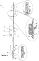
- figure 4 shows an alternative embodiment wherein the secondary lock 200 (not shown) is arranged to act on a lug 150 that is formed on the drive rail 140 of the bolting system 130. That is to say, the drive rail 140 of the bolting system 130 and the moving part may comprise a lug 150 affixed to, and moveable with, the drive rail 140.
- the locking mechanism 100 is shown with a handle aperture (which can be turned by a spindle and lever such as a handle or wrench - not shown), a cylinder hole 124 and a casing housing the internal mechanism.
- the bolting system 130 is shown with a deadbolt 132 and a latch bolt 134.
- the bolting system 130 also includes a drive rail 140 and a cover 142. Attached fast to the drive rail 140 is a lug 150, and this is the only adaptation to the otherwise standard bolting system 130.
- the lug 150 is shown as an appropriately sized rectangle.
- the lug 150 is secured fast to the drive rail in any suitable manner, for instance welding or mechanical fix.
- the lug 150 is shown with an aperture 152.
- the aperture 152 extends through the lug 150, but could also be a recess. That is to say the aperture 152 may be an opening provided as a through hole or as a depression configured to receive the bolt 210 It will be appreciated that the aperture 152 is arranged to engage the bolt 210 of the secondary lock 200, when the drive rail and therefore lug 150 have been actuated to the clocking position and the secondary lock 200 actuated.
- the lug 150 is arranged within a mortice formed in the edge of the door and sized appropriately to allow the full travel of movement of the lug 150.
- the operation of the secondary lock 200 is shown in relation to the previous embodiment wherein the secondary lock 200 acts on a lug 150.
- the lug 150 slides vertically.
- the secondary lock 200 acts on bolts
- the bolts may slide horizontally or may pivot.
- the principal remains the same that the bolt of the secondary lock 200 moves in a direction other than the direction of the moving part, in the exemplary embodiments perpendicular to the inside face of the door, and when engaged with the recess or aperture, prevents movement of the part in the opposed, unlocking direction.
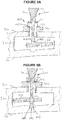
- a door 300 has an inside face 310, an outside face 320 and a recess (or cavity) 330 to accommodate the moving part of the bolting system 130.
- the lug 150 is shown having slid along a length of the door between an unlocked position wherein the bolts of the bolting system 130 are not thrown ( Figure 5A ) and a locked position wherein the bolts of the bolting system 130 are thrown ( Figure 5B ).
- the aperture 152 of the lug 150 is not aligned with the secondary lock 200.
- the aperture 152 is aligned with the secondary lock 200.
- the secondary lock 200 comprises a bolt 210 and a housing 220.
- the housing 220 includes fixings (for example screws) to attach securely to the inside face of the door.
- the housing 220 restrains the bolt 210 to the door and provides the reaction to resist movement of the lug 150 moving past.
- the secondary lock 200 includes an actuator 218 (i.e. a mechanism) to allow the bolt 210 to be actuated between a bolted position ( Figure 5B ) and a reset position ( Figure 5A ).
- the actuator 218 is shown as comprising a guide slot 221 and stop 222 in the housing 220 and a cooperating protrusion 211 on the bolt 210.
- the actuator 218 allows the bolt 210 to slide in one angular rotation, but when in an alternative angular orientation prevents the bolt form being engaged.
- a biasing member such as a spring may be arranged to urge the bolt 210 towards the bolted position.
- the bolt 210 includes a pin 212 that engages and penetrates the aperture 152, and a handle portion 214 that can be used to manually operate the secondary lock 200. For instance, to withdraw the pin 212 of the bolt 210 from the aperture 152 against the bias of the spring and to twist the bolt so as to engage the actuator 218 holding the bolt in the reset position.
- the handle 214 can be used to twist the bolt 210 to disengage the actuator 218 and bolt the secondary lock 200.
- a location feature 215 may be provided to receive the pin 212 of the bolt 210 to guide the pin 212 as it is extended into and out of the recess/aperture 152 and/or to provide greater resistance to bending forces generated when the lug 150 is urged to move away from the locked position ( Figure 5B ).
- the location feature 215 is defined/provided in the door or door frame as an engagement space 217 (e.g. a recess), configured to receive a distal tip 216 of the bolt 210 (i.e. the end of the bolt 210 distal to the handle 214 of the bolt 210).
- an engagement space 217 e.g. a recess
- no location feature e.g. recess
- a housing 500 (which may also be termed a box or keep) encases the lug 150, and the housing 500 comprises a location feature 215 in the form of a passage 510 for receiving the bolt 210.
- the housing 500 may be fixed to the door.
- the housing 500 may comprise a first wall 530 spaced apart from a second wall 532, the lug 150 being located between the first wall 530 and second wall 532.
- the first wall 530 is located between the housing 220 (and inner material of the door 600) and the lug 150.
- the second wall 532 is located closer to the external surface of the door 600 than the first wall 530.
- a passage 510 may be provided in a face of the housing 500.
- the passage 510 may be provided as an aperture or hole in the first wall 530 of the housing 500.
- the passage 510 may be aligned with the recess/aperture 152 in the lug 150 when bolt 210 is in the bolted position.
- the pin 212 of the bolt 210 may extend through the passage 510 in a first side 514 (i.e. the first wall 530) of the housing 500 and into the housing 510 to engage with the lug 150.
- a second side i.e. second wall 532
- the bolt 210 is locatable by the housing 500 by virtue of the passage 510 in the first wall 530 of the housing 500, and the bolt's location is shielded from from the outside surface of the door 600 by the second wall 532. Hence it is not possible, even by punching or drilling holes in the outside surface of the door 600, to gain access to the bolt 210.
- the actuator 218 may be manually actuated. That is to say the actuator comprises a configuration and/or mechanism which is operable by a user twisting/pushing or otherwise urging the bolt to move from one position to another.
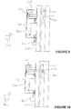
- Figures 9, 10 show further example in which the actuator 218 comprises a motor 400 operable to translate the bolt 210 to the reset position (as shown in Figure 9 ) and/or the bolted position (as shown in Figure 10 ).
- the motor 400 may be provided as a linear or rotary solenoid mechanism, or some other form of electric motor. Hence the motor 400 may be operated by a user, for example by operating a control unit 520, to move the bolt 210 to either the reset or engaged/bolted position.
- the motor 400 and control unit 520 may be provided in a casing 410, and the casing 410, and hence the casing and/or motor 400 and/or control unit 520 may be mounted to a door 600.
- the control unit 520 may operated via a manually operated switch 522, or via a remote control 524, where the remote control 524 and control unit 520 are operable to be in wireless communication with each other.
- the actuator 218 may be remotely operable and/or manually operable.
- the advantage of all of the examples of the present disclosure is that a user may engage the secondary lock 200 from one side of a door (i.e. normally inside of the building to which the door is attached).
- the remote control example (for example as shown in Figures 9, 10 ) provides an additional advantage that a user may securely lock a door 600 from both sides (e.g. inside and outside of the building to which the door attached).
- the terms inside, outside, vertical and horizontal and the like have been used in relation to the door when installed on a building.
- the door is installed in a vertical plane, and hinged in a vertical manner.
- the closure may be installed in different configurations, for instance the door may be horizontally opening or the door may be an internal door where both sides are inside.
- the terminology can be adapted to fit these circumstances, and in particular, the term inside is the side not being tampered from.
Landscapes
- Engineering & Computer Science (AREA)
- Mechanical Engineering (AREA)
- Lock And Its Accessories (AREA)
Applications Claiming Priority (1)
| Application Number | Priority Date | Filing Date | Title |
|---|---|---|---|
| GBGB1715762.9A GB201715762D0 (en) | 2017-09-28 | 2017-09-28 | Improved door locking mechanism |
Publications (2)
| Publication Number | Publication Date |
|---|---|
| EP3461976A1 true EP3461976A1 (fr) | 2019-04-03 |
| EP3461976B1 EP3461976B1 (fr) | 2021-03-10 |
Family
ID=60270388
Family Applications (1)
| Application Number | Title | Priority Date | Filing Date |
|---|---|---|---|
| EP18196971.8A Active EP3461976B1 (fr) | 2017-09-28 | 2018-09-26 | Mécanisme de verrouillage de portes amélioré |
Country Status (2)
| Country | Link |
|---|---|
| EP (1) | EP3461976B1 (fr) |
| GB (1) | GB201715762D0 (fr) |
Cited By (1)
| Publication number | Priority date | Publication date | Assignee | Title |
|---|---|---|---|---|
| US20240328204A1 (en) * | 2023-03-30 | 2024-10-03 | William Davis | Door Lock Assembly |
Citations (9)
| Publication number | Priority date | Publication date | Assignee | Title |
|---|---|---|---|---|
| FR341859A (fr) * | 1904-04-02 | 1904-08-22 | Boleslas Zwierski | Perfectionnement aux crémones |
| US3771339A (en) * | 1972-01-24 | 1973-11-13 | E Smith | Protective apparatus for door locks employing latch-rods |
| US4073525A (en) * | 1977-06-09 | 1978-02-14 | Marcelo Gurule | Door latch securing device |
| EP0173987A1 (fr) * | 1984-09-07 | 1986-03-12 | HÖRMANN KG Freisen | Serrure complémentaire pour portes avec système de fermeture de sécurité |
| DE3836976A1 (de) * | 1987-11-21 | 1989-06-01 | Geze Gmbh & Co | Treibstangenbeschlag fuer einen fluegel eines fensters, einer tuer oder dergleichen |
| DE29807860U1 (de) * | 1998-05-01 | 1998-08-27 | Berchtold, Reinhold, 87651 Bidingen | Sicherheitsverriegelungseinrichtung für Türen o.dgl. |
| WO2001079633A1 (fr) * | 2000-04-14 | 2001-10-25 | Henri Morel | Procede de condamnation d'une serrure a larder multipoints |
| WO2008145302A2 (fr) * | 2007-05-31 | 2008-12-04 | Dirak Dieter Ramsauer Konstruktionselemente Gmbh & Co. Kg | Dispositif de sécurité pour une fermeture à levier pivotant |
| ITUB20153858A1 (it) * | 2015-09-24 | 2017-03-24 | Pierluigi Oliana | Metodo di montaggio di un dispositivo di bloccaggio selettivo per sistemi di chiusura a cremonese e relativo dispositivo di bloccaggio |
-
2017
- 2017-09-28 GB GBGB1715762.9A patent/GB201715762D0/en not_active Ceased
-
2018
- 2018-09-26 EP EP18196971.8A patent/EP3461976B1/fr active Active
Patent Citations (9)
| Publication number | Priority date | Publication date | Assignee | Title |
|---|---|---|---|---|
| FR341859A (fr) * | 1904-04-02 | 1904-08-22 | Boleslas Zwierski | Perfectionnement aux crémones |
| US3771339A (en) * | 1972-01-24 | 1973-11-13 | E Smith | Protective apparatus for door locks employing latch-rods |
| US4073525A (en) * | 1977-06-09 | 1978-02-14 | Marcelo Gurule | Door latch securing device |
| EP0173987A1 (fr) * | 1984-09-07 | 1986-03-12 | HÖRMANN KG Freisen | Serrure complémentaire pour portes avec système de fermeture de sécurité |
| DE3836976A1 (de) * | 1987-11-21 | 1989-06-01 | Geze Gmbh & Co | Treibstangenbeschlag fuer einen fluegel eines fensters, einer tuer oder dergleichen |
| DE29807860U1 (de) * | 1998-05-01 | 1998-08-27 | Berchtold, Reinhold, 87651 Bidingen | Sicherheitsverriegelungseinrichtung für Türen o.dgl. |
| WO2001079633A1 (fr) * | 2000-04-14 | 2001-10-25 | Henri Morel | Procede de condamnation d'une serrure a larder multipoints |
| WO2008145302A2 (fr) * | 2007-05-31 | 2008-12-04 | Dirak Dieter Ramsauer Konstruktionselemente Gmbh & Co. Kg | Dispositif de sécurité pour une fermeture à levier pivotant |
| ITUB20153858A1 (it) * | 2015-09-24 | 2017-03-24 | Pierluigi Oliana | Metodo di montaggio di un dispositivo di bloccaggio selettivo per sistemi di chiusura a cremonese e relativo dispositivo di bloccaggio |
Cited By (1)
| Publication number | Priority date | Publication date | Assignee | Title |
|---|---|---|---|---|
| US20240328204A1 (en) * | 2023-03-30 | 2024-10-03 | William Davis | Door Lock Assembly |
Also Published As
| Publication number | Publication date |
|---|---|
| GB201715762D0 (en) | 2017-11-15 |
| EP3461976B1 (fr) | 2021-03-10 |
Similar Documents
| Publication | Publication Date | Title |
|---|---|---|
| US9487975B2 (en) | Security systems for entrance barriers | |
| US5544924A (en) | Security mechanism for securing a movable closure | |
| US9765550B2 (en) | Passive door lock mechanisms | |
| KR101594823B1 (ko) | 통합 도어 위치센서가 구비된 도어 록 | |
| EP2586951B1 (fr) | Coffre-fort de sécurité et terminal à libre-service pourvu dudit coffre-fort | |
| EP2208840A2 (fr) | Mécanisme de verrouillage | |
| CA2246211A1 (fr) | Serrure a combinaisons a pene dormant avec pene demi-tour automatique | |
| EP3461976B1 (fr) | Mécanisme de verrouillage de portes amélioré | |
| WO2017068518A1 (fr) | Système de verrouillage de porte multipoints | |
| US11702864B2 (en) | Automatic locking-deadbolt assembly in a door | |
| KR101986613B1 (ko) | 슬라이딩 도어용 도어락장치 | |
| US5280976A (en) | Door security device | |
| US12559979B2 (en) | Multi-lock comprising a keyless lock for closures | |
| US4841673A (en) | Security window system | |
| EA012235B1 (ru) | Врезной замок и стопорный элемент сцепления | |
| EP3924579A1 (fr) | Verrou pour fermeture coulissante | |
| US4445718A (en) | Security doors | |
| GB2408773A (en) | Lock actuation mechanism comprising spring-loaded locking pin | |
| GB2612081A (en) | Lock | |
| WO2022054026A1 (fr) | Serrure | |
| JP2007040080A (ja) | 引き違いドア等の錠装置 | |
| HK1020444A (en) | Deadbolt combination lock system |
Legal Events
| Date | Code | Title | Description |
|---|---|---|---|
| PUAI | Public reference made under article 153(3) epc to a published international application that has entered the european phase |
Free format text: ORIGINAL CODE: 0009012 |
|
| STAA | Information on the status of an ep patent application or granted ep patent |
Free format text: STATUS: THE APPLICATION HAS BEEN PUBLISHED |
|
| AK | Designated contracting states |
Kind code of ref document: A1 Designated state(s): AL AT BE BG CH CY CZ DE DK EE ES FI FR GB GR HR HU IE IS IT LI LT LU LV MC MK MT NL NO PL PT RO RS SE SI SK SM TR |
|
| AX | Request for extension of the european patent |
Extension state: BA ME |
|
| 111L | Licence recorded |
Designated state(s): AL AT BE BG CH CY CZ DE DK EE ES FI FR GB GR HR HU IE IS IT LT LU LV MC MK MT NL NO PL PT RO RS SE SI SK SM TR Free format text: EXCLUSIVE LICENSE Name of requester: UAP LIMITED, GB Effective date: 20190619 |
|
| STAA | Information on the status of an ep patent application or granted ep patent |
Free format text: STATUS: REQUEST FOR EXAMINATION WAS MADE |
|
| 17P | Request for examination filed |
Effective date: 20190930 |
|
| RBV | Designated contracting states (corrected) |
Designated state(s): AL AT BE BG CH CY CZ DE DK EE ES FI FR GB GR HR HU IE IS IT LI LT LU LV MC MK MT NL NO PL PT RO RS SE SI SK SM TR |
|
| GRAP | Despatch of communication of intention to grant a patent |
Free format text: ORIGINAL CODE: EPIDOSNIGR1 |
|
| STAA | Information on the status of an ep patent application or granted ep patent |
Free format text: STATUS: GRANT OF PATENT IS INTENDED |
|
| RIC1 | Information provided on ipc code assigned before grant |
Ipc: E05B 47/06 20060101ALI20200828BHEP Ipc: E05C 9/00 20060101AFI20200828BHEP Ipc: E05B 17/20 20060101ALI20200828BHEP |
|
| INTG | Intention to grant announced |
Effective date: 20200921 |
|
| GRAS | Grant fee paid |
Free format text: ORIGINAL CODE: EPIDOSNIGR3 |
|
| GRAA | (expected) grant |
Free format text: ORIGINAL CODE: 0009210 |
|
| STAA | Information on the status of an ep patent application or granted ep patent |
Free format text: STATUS: THE PATENT HAS BEEN GRANTED |
|
| 111L | Licence recorded |
Designated state(s): AL AT BE BG CH CY CZ DE DK EE ES FI FR GB GR HR HU IE IS IT LT LU LV MC MK MT NL NO PL PT RO RS SE SI SK SM TR Free format text: EXCLUSIVE LICENSE Name of requester: UAP LIMITED, GB Effective date: 20190619 |
|
| AK | Designated contracting states |
Kind code of ref document: B1 Designated state(s): AL AT BE BG CH CY CZ DE DK EE ES FI FR GB GR HR HU IE IS IT LI LT LU LV MC MK MT NL NO PL PT RO RS SE SI SK SM TR |
|
| REG | Reference to a national code |
Ref country code: GB Ref legal event code: FG4D |
|
| REG | Reference to a national code |
Ref country code: AT Ref legal event code: REF Ref document number: 1369968 Country of ref document: AT Kind code of ref document: T Effective date: 20210315 Ref country code: CH Ref legal event code: EP |
|
| REG | Reference to a national code |
Ref country code: IE Ref legal event code: FG4D |
|
| REG | Reference to a national code |
Ref country code: DE Ref legal event code: R096 Ref document number: 602018013650 Country of ref document: DE |
|
| REG | Reference to a national code |
Ref country code: LT Ref legal event code: MG9D |
|
| PG25 | Lapsed in a contracting state [announced via postgrant information from national office to epo] |
Ref country code: BG Free format text: LAPSE BECAUSE OF FAILURE TO SUBMIT A TRANSLATION OF THE DESCRIPTION OR TO PAY THE FEE WITHIN THE PRESCRIBED TIME-LIMIT Effective date: 20210610 Ref country code: HR Free format text: LAPSE BECAUSE OF FAILURE TO SUBMIT A TRANSLATION OF THE DESCRIPTION OR TO PAY THE FEE WITHIN THE PRESCRIBED TIME-LIMIT Effective date: 20210310 Ref country code: FI Free format text: LAPSE BECAUSE OF FAILURE TO SUBMIT A TRANSLATION OF THE DESCRIPTION OR TO PAY THE FEE WITHIN THE PRESCRIBED TIME-LIMIT Effective date: 20210310 Ref country code: GR Free format text: LAPSE BECAUSE OF FAILURE TO SUBMIT A TRANSLATION OF THE DESCRIPTION OR TO PAY THE FEE WITHIN THE PRESCRIBED TIME-LIMIT Effective date: 20210611 Ref country code: NO Free format text: LAPSE BECAUSE OF FAILURE TO SUBMIT A TRANSLATION OF THE DESCRIPTION OR TO PAY THE FEE WITHIN THE PRESCRIBED TIME-LIMIT Effective date: 20210610 Ref country code: LT Free format text: LAPSE BECAUSE OF FAILURE TO SUBMIT A TRANSLATION OF THE DESCRIPTION OR TO PAY THE FEE WITHIN THE PRESCRIBED TIME-LIMIT Effective date: 20210310 |
|
| REG | Reference to a national code |
Ref country code: AT Ref legal event code: MK05 Ref document number: 1369968 Country of ref document: AT Kind code of ref document: T Effective date: 20210310 |
|
| REG | Reference to a national code |
Ref country code: NL Ref legal event code: MP Effective date: 20210310 |
|
| PG25 | Lapsed in a contracting state [announced via postgrant information from national office to epo] |
Ref country code: RS Free format text: LAPSE BECAUSE OF FAILURE TO SUBMIT A TRANSLATION OF THE DESCRIPTION OR TO PAY THE FEE WITHIN THE PRESCRIBED TIME-LIMIT Effective date: 20210310 Ref country code: LV Free format text: LAPSE BECAUSE OF FAILURE TO SUBMIT A TRANSLATION OF THE DESCRIPTION OR TO PAY THE FEE WITHIN THE PRESCRIBED TIME-LIMIT Effective date: 20210310 Ref country code: SE Free format text: LAPSE BECAUSE OF FAILURE TO SUBMIT A TRANSLATION OF THE DESCRIPTION OR TO PAY THE FEE WITHIN THE PRESCRIBED TIME-LIMIT Effective date: 20210310 |
|
| PG25 | Lapsed in a contracting state [announced via postgrant information from national office to epo] |
Ref country code: NL Free format text: LAPSE BECAUSE OF FAILURE TO SUBMIT A TRANSLATION OF THE DESCRIPTION OR TO PAY THE FEE WITHIN THE PRESCRIBED TIME-LIMIT Effective date: 20210310 |
|
| PG25 | Lapsed in a contracting state [announced via postgrant information from national office to epo] |
Ref country code: SM Free format text: LAPSE BECAUSE OF FAILURE TO SUBMIT A TRANSLATION OF THE DESCRIPTION OR TO PAY THE FEE WITHIN THE PRESCRIBED TIME-LIMIT Effective date: 20210310 Ref country code: CZ Free format text: LAPSE BECAUSE OF FAILURE TO SUBMIT A TRANSLATION OF THE DESCRIPTION OR TO PAY THE FEE WITHIN THE PRESCRIBED TIME-LIMIT Effective date: 20210310 Ref country code: EE Free format text: LAPSE BECAUSE OF FAILURE TO SUBMIT A TRANSLATION OF THE DESCRIPTION OR TO PAY THE FEE WITHIN THE PRESCRIBED TIME-LIMIT Effective date: 20210310 Ref country code: AT Free format text: LAPSE BECAUSE OF FAILURE TO SUBMIT A TRANSLATION OF THE DESCRIPTION OR TO PAY THE FEE WITHIN THE PRESCRIBED TIME-LIMIT Effective date: 20210310 |
|
| PG25 | Lapsed in a contracting state [announced via postgrant information from national office to epo] |
Ref country code: IS Free format text: LAPSE BECAUSE OF FAILURE TO SUBMIT A TRANSLATION OF THE DESCRIPTION OR TO PAY THE FEE WITHIN THE PRESCRIBED TIME-LIMIT Effective date: 20210710 Ref country code: PL Free format text: LAPSE BECAUSE OF FAILURE TO SUBMIT A TRANSLATION OF THE DESCRIPTION OR TO PAY THE FEE WITHIN THE PRESCRIBED TIME-LIMIT Effective date: 20210310 Ref country code: PT Free format text: LAPSE BECAUSE OF FAILURE TO SUBMIT A TRANSLATION OF THE DESCRIPTION OR TO PAY THE FEE WITHIN THE PRESCRIBED TIME-LIMIT Effective date: 20210712 Ref country code: SK Free format text: LAPSE BECAUSE OF FAILURE TO SUBMIT A TRANSLATION OF THE DESCRIPTION OR TO PAY THE FEE WITHIN THE PRESCRIBED TIME-LIMIT Effective date: 20210310 Ref country code: RO Free format text: LAPSE BECAUSE OF FAILURE TO SUBMIT A TRANSLATION OF THE DESCRIPTION OR TO PAY THE FEE WITHIN THE PRESCRIBED TIME-LIMIT Effective date: 20210310 |
|
| REG | Reference to a national code |
Ref country code: DE Ref legal event code: R097 Ref document number: 602018013650 Country of ref document: DE |
|
| PLBE | No opposition filed within time limit |
Free format text: ORIGINAL CODE: 0009261 |
|
| STAA | Information on the status of an ep patent application or granted ep patent |
Free format text: STATUS: NO OPPOSITION FILED WITHIN TIME LIMIT |
|
| PG25 | Lapsed in a contracting state [announced via postgrant information from national office to epo] |
Ref country code: ES Free format text: LAPSE BECAUSE OF FAILURE TO SUBMIT A TRANSLATION OF THE DESCRIPTION OR TO PAY THE FEE WITHIN THE PRESCRIBED TIME-LIMIT Effective date: 20210310 Ref country code: DK Free format text: LAPSE BECAUSE OF FAILURE TO SUBMIT A TRANSLATION OF THE DESCRIPTION OR TO PAY THE FEE WITHIN THE PRESCRIBED TIME-LIMIT Effective date: 20210310 Ref country code: AL Free format text: LAPSE BECAUSE OF FAILURE TO SUBMIT A TRANSLATION OF THE DESCRIPTION OR TO PAY THE FEE WITHIN THE PRESCRIBED TIME-LIMIT Effective date: 20210310 |
|
| REG | Reference to a national code |
Ref country code: GB Ref legal event code: 732E Free format text: REGISTERED BETWEEN 20220106 AND 20220112 |
|
| 26N | No opposition filed |
Effective date: 20211213 |
|
| PG25 | Lapsed in a contracting state [announced via postgrant information from national office to epo] |
Ref country code: SI Free format text: LAPSE BECAUSE OF FAILURE TO SUBMIT A TRANSLATION OF THE DESCRIPTION OR TO PAY THE FEE WITHIN THE PRESCRIBED TIME-LIMIT Effective date: 20210310 |
|
| PG25 | Lapsed in a contracting state [announced via postgrant information from national office to epo] |
Ref country code: IT Free format text: LAPSE BECAUSE OF FAILURE TO SUBMIT A TRANSLATION OF THE DESCRIPTION OR TO PAY THE FEE WITHIN THE PRESCRIBED TIME-LIMIT Effective date: 20210310 |
|
| REG | Reference to a national code |
Ref country code: BE Ref legal event code: MM Effective date: 20210930 |
|
| PG25 | Lapsed in a contracting state [announced via postgrant information from national office to epo] |
Ref country code: IS Free format text: LAPSE BECAUSE OF FAILURE TO SUBMIT A TRANSLATION OF THE DESCRIPTION OR TO PAY THE FEE WITHIN THE PRESCRIBED TIME-LIMIT Effective date: 20210710 Ref country code: MC Free format text: LAPSE BECAUSE OF FAILURE TO SUBMIT A TRANSLATION OF THE DESCRIPTION OR TO PAY THE FEE WITHIN THE PRESCRIBED TIME-LIMIT Effective date: 20210310 |
|
| PG25 | Lapsed in a contracting state [announced via postgrant information from national office to epo] |
Ref country code: LU Free format text: LAPSE BECAUSE OF NON-PAYMENT OF DUE FEES Effective date: 20210926 Ref country code: BE Free format text: LAPSE BECAUSE OF NON-PAYMENT OF DUE FEES Effective date: 20210930 |
|
| PG25 | Lapsed in a contracting state [announced via postgrant information from national office to epo] |
Ref country code: CY Free format text: LAPSE BECAUSE OF FAILURE TO SUBMIT A TRANSLATION OF THE DESCRIPTION OR TO PAY THE FEE WITHIN THE PRESCRIBED TIME-LIMIT Effective date: 20210310 |
|
| PG25 | Lapsed in a contracting state [announced via postgrant information from national office to epo] |
Ref country code: HU Free format text: LAPSE BECAUSE OF FAILURE TO SUBMIT A TRANSLATION OF THE DESCRIPTION OR TO PAY THE FEE WITHIN THE PRESCRIBED TIME-LIMIT; INVALID AB INITIO Effective date: 20180926 |
|
| REG | Reference to a national code |
Ref country code: DE Ref legal event code: R081 Ref document number: 602018013650 Country of ref document: DE Owner name: UAP LTD., GB Free format text: FORMER OWNER: DEDLOK LTD, BRADFORD, GB |
|
| PG25 | Lapsed in a contracting state [announced via postgrant information from national office to epo] |
Ref country code: MK Free format text: LAPSE BECAUSE OF FAILURE TO SUBMIT A TRANSLATION OF THE DESCRIPTION OR TO PAY THE FEE WITHIN THE PRESCRIBED TIME-LIMIT Effective date: 20210310 |
|
| PG25 | Lapsed in a contracting state [announced via postgrant information from national office to epo] |
Ref country code: MT Free format text: LAPSE BECAUSE OF FAILURE TO SUBMIT A TRANSLATION OF THE DESCRIPTION OR TO PAY THE FEE WITHIN THE PRESCRIBED TIME-LIMIT Effective date: 20210310 |
|
| REG | Reference to a national code |
Ref country code: CH Ref legal event code: U11 Free format text: ST27 STATUS EVENT CODE: U-0-0-U10-U11 (AS PROVIDED BY THE NATIONAL OFFICE) Effective date: 20251001 |
|
| PGFP | Annual fee paid to national office [announced via postgrant information from national office to epo] |
Ref country code: DE Payment date: 20250926 Year of fee payment: 8 |
|
| PGFP | Annual fee paid to national office [announced via postgrant information from national office to epo] |
Ref country code: GB Payment date: 20250716 Year of fee payment: 8 |
|
| PGFP | Annual fee paid to national office [announced via postgrant information from national office to epo] |
Ref country code: FR Payment date: 20250925 Year of fee payment: 8 |
|
| PGFP | Annual fee paid to national office [announced via postgrant information from national office to epo] |
Ref country code: IE Payment date: 20250716 Year of fee payment: 8 |
|
| PG25 | Lapsed in a contracting state [announced via postgrant information from national office to epo] |
Ref country code: TR Free format text: LAPSE BECAUSE OF FAILURE TO SUBMIT A TRANSLATION OF THE DESCRIPTION OR TO PAY THE FEE WITHIN THE PRESCRIBED TIME-LIMIT Effective date: 20210310 |
|
| PGFP | Annual fee paid to national office [announced via postgrant information from national office to epo] |
Ref country code: CH Payment date: 20251001 Year of fee payment: 8 |