EP3461987B1 - Revêtement de structure architecturale - Google Patents
Revêtement de structure architecturale Download PDFInfo
- Publication number
- EP3461987B1 EP3461987B1 EP18196087.3A EP18196087A EP3461987B1 EP 3461987 B1 EP3461987 B1 EP 3461987B1 EP 18196087 A EP18196087 A EP 18196087A EP 3461987 B1 EP3461987 B1 EP 3461987B1
- Authority
- EP
- European Patent Office
- Prior art keywords
- covering
- operating system
- shift arm
- operating element
- mode
- Prior art date
- Legal status (The legal status is an assumption and is not a legal conclusion. Google has not performed a legal analysis and makes no representation as to the accuracy of the status listed.)
- Active
Links
Images




Classifications
-
- E—FIXED CONSTRUCTIONS
- E06—DOORS, WINDOWS, SHUTTERS, OR ROLLER BLINDS IN GENERAL; LADDERS
- E06B—FIXED OR MOVABLE CLOSURES FOR OPENINGS IN BUILDINGS, VEHICLES, FENCES OR LIKE ENCLOSURES IN GENERAL, e.g. DOORS, WINDOWS, BLINDS, GATES
- E06B9/00—Screening or protective devices for wall or similar openings, with or without operating or securing mechanisms; Closures of similar construction
- E06B9/24—Screens or other constructions affording protection against light, especially against sunshine; Similar screens for privacy or appearance; Slat blinds
- E06B9/26—Lamellar or like blinds, e.g. venetian blinds
- E06B9/28—Lamellar or like blinds, e.g. venetian blinds with horizontal lamellae, e.g. non-liftable
- E06B9/30—Lamellar or like blinds, e.g. venetian blinds with horizontal lamellae, e.g. non-liftable liftable
- E06B9/32—Operating, guiding, or securing devices therefor
- E06B9/322—Details of operating devices, e.g. pulleys, brakes, spring drums, drives
-
- E—FIXED CONSTRUCTIONS
- E06—DOORS, WINDOWS, SHUTTERS, OR ROLLER BLINDS IN GENERAL; LADDERS
- E06B—FIXED OR MOVABLE CLOSURES FOR OPENINGS IN BUILDINGS, VEHICLES, FENCES OR LIKE ENCLOSURES IN GENERAL, e.g. DOORS, WINDOWS, BLINDS, GATES
- E06B9/00—Screening or protective devices for wall or similar openings, with or without operating or securing mechanisms; Closures of similar construction
- E06B9/24—Screens or other constructions affording protection against light, especially against sunshine; Similar screens for privacy or appearance; Slat blinds
- E06B9/26—Lamellar or like blinds, e.g. venetian blinds
- E06B9/28—Lamellar or like blinds, e.g. venetian blinds with horizontal lamellae, e.g. non-liftable
- E06B9/34—Lamellar or like blinds, e.g. venetian blinds with horizontal lamellae, e.g. non-liftable roller-type; Roller shutters with adjustable lamellae
-
- E—FIXED CONSTRUCTIONS
- E06—DOORS, WINDOWS, SHUTTERS, OR ROLLER BLINDS IN GENERAL; LADDERS
- E06B—FIXED OR MOVABLE CLOSURES FOR OPENINGS IN BUILDINGS, VEHICLES, FENCES OR LIKE ENCLOSURES IN GENERAL, e.g. DOORS, WINDOWS, BLINDS, GATES
- E06B9/00—Screening or protective devices for wall or similar openings, with or without operating or securing mechanisms; Closures of similar construction
- E06B9/24—Screens or other constructions affording protection against light, especially against sunshine; Similar screens for privacy or appearance; Slat blinds
- E06B9/40—Roller blinds
- E06B9/42—Parts or details of roller blinds, e.g. suspension devices, blind boxes
-
- E—FIXED CONSTRUCTIONS
- E06—DOORS, WINDOWS, SHUTTERS, OR ROLLER BLINDS IN GENERAL; LADDERS
- E06B—FIXED OR MOVABLE CLOSURES FOR OPENINGS IN BUILDINGS, VEHICLES, FENCES OR LIKE ENCLOSURES IN GENERAL, e.g. DOORS, WINDOWS, BLINDS, GATES
- E06B9/00—Screening or protective devices for wall or similar openings, with or without operating or securing mechanisms; Closures of similar construction
- E06B9/56—Operating, guiding or securing devices or arrangements for roll-type closures; Spring drums; Tape drums; Counterweighting arrangements therefor
- E06B9/78—Operating, guiding or securing devices or arrangements for roll-type closures; Spring drums; Tape drums; Counterweighting arrangements therefor for direct manual operation, e.g. by tassels, by handles
-
- E—FIXED CONSTRUCTIONS
- E06—DOORS, WINDOWS, SHUTTERS, OR ROLLER BLINDS IN GENERAL; LADDERS
- E06B—FIXED OR MOVABLE CLOSURES FOR OPENINGS IN BUILDINGS, VEHICLES, FENCES OR LIKE ENCLOSURES IN GENERAL, e.g. DOORS, WINDOWS, BLINDS, GATES
- E06B9/00—Screening or protective devices for wall or similar openings, with or without operating or securing mechanisms; Closures of similar construction
- E06B9/24—Screens or other constructions affording protection against light, especially against sunshine; Similar screens for privacy or appearance; Slat blinds
- E06B2009/2423—Combinations of at least two screens
- E06B2009/2435—Two vertical sheets and slats in-between
-
- E—FIXED CONSTRUCTIONS
- E06—DOORS, WINDOWS, SHUTTERS, OR ROLLER BLINDS IN GENERAL; LADDERS
- E06B—FIXED OR MOVABLE CLOSURES FOR OPENINGS IN BUILDINGS, VEHICLES, FENCES OR LIKE ENCLOSURES IN GENERAL, e.g. DOORS, WINDOWS, BLINDS, GATES
- E06B9/00—Screening or protective devices for wall or similar openings, with or without operating or securing mechanisms; Closures of similar construction
- E06B9/56—Operating, guiding or securing devices or arrangements for roll-type closures; Spring drums; Tape drums; Counterweighting arrangements therefor
- E06B9/78—Operating, guiding or securing devices or arrangements for roll-type closures; Spring drums; Tape drums; Counterweighting arrangements therefor for direct manual operation, e.g. by tassels, by handles
- E06B2009/785—Operating, guiding or securing devices or arrangements for roll-type closures; Spring drums; Tape drums; Counterweighting arrangements therefor for direct manual operation, e.g. by tassels, by handles by belts, straps, bands, tapes, cords, tassels
-
- E—FIXED CONSTRUCTIONS
- E06—DOORS, WINDOWS, SHUTTERS, OR ROLLER BLINDS IN GENERAL; LADDERS
- E06B—FIXED OR MOVABLE CLOSURES FOR OPENINGS IN BUILDINGS, VEHICLES, FENCES OR LIKE ENCLOSURES IN GENERAL, e.g. DOORS, WINDOWS, BLINDS, GATES
- E06B9/00—Screening or protective devices for wall or similar openings, with or without operating or securing mechanisms; Closures of similar construction
- E06B9/56—Operating, guiding or securing devices or arrangements for roll-type closures; Spring drums; Tape drums; Counterweighting arrangements therefor
- E06B9/80—Safety measures against dropping or unauthorised opening; Braking or immobilising devices; Devices for limiting unrolling
- E06B9/82—Safety measures against dropping or unauthorised opening; Braking or immobilising devices; Devices for limiting unrolling automatic
- E06B9/90—Safety measures against dropping or unauthorised opening; Braking or immobilising devices; Devices for limiting unrolling automatic for immobilising the closure member in various chosen positions
- E06B2009/905—Safety measures against dropping or unauthorised opening; Braking or immobilising devices; Devices for limiting unrolling automatic for immobilising the closure member in various chosen positions using wrap spring clutches
-
- E—FIXED CONSTRUCTIONS
- E06—DOORS, WINDOWS, SHUTTERS, OR ROLLER BLINDS IN GENERAL; LADDERS
- E06B—FIXED OR MOVABLE CLOSURES FOR OPENINGS IN BUILDINGS, VEHICLES, FENCES OR LIKE ENCLOSURES IN GENERAL, e.g. DOORS, WINDOWS, BLINDS, GATES
- E06B9/00—Screening or protective devices for wall or similar openings, with or without operating or securing mechanisms; Closures of similar construction
- E06B9/24—Screens or other constructions affording protection against light, especially against sunshine; Similar screens for privacy or appearance; Slat blinds
- E06B9/26—Lamellar or like blinds, e.g. venetian blinds
- E06B9/264—Combinations of lamellar blinds with roller shutters, screen windows, windows, or double panes; Lamellar blinds with special devices
-
- E—FIXED CONSTRUCTIONS
- E06—DOORS, WINDOWS, SHUTTERS, OR ROLLER BLINDS IN GENERAL; LADDERS
- E06B—FIXED OR MOVABLE CLOSURES FOR OPENINGS IN BUILDINGS, VEHICLES, FENCES OR LIKE ENCLOSURES IN GENERAL, e.g. DOORS, WINDOWS, BLINDS, GATES
- E06B9/00—Screening or protective devices for wall or similar openings, with or without operating or securing mechanisms; Closures of similar construction
- E06B9/56—Operating, guiding or securing devices or arrangements for roll-type closures; Spring drums; Tape drums; Counterweighting arrangements therefor
- E06B9/80—Safety measures against dropping or unauthorised opening; Braking or immobilising devices; Devices for limiting unrolling
- E06B9/82—Safety measures against dropping or unauthorised opening; Braking or immobilising devices; Devices for limiting unrolling automatic
- E06B9/90—Safety measures against dropping or unauthorised opening; Braking or immobilising devices; Devices for limiting unrolling automatic for immobilising the closure member in various chosen positions
Definitions
- the present disclosure relates generally to the field of architectural-structure coverings, and relates more particularly to methods and apparatuses for operating a covering for an architectural structure.
- Architectural-structure coverings may selectively cover an architectural structure such as, for example, a window, a doorway, a skylight, a hallway, an archway, a portion of a wall, etc.
- architectural-structure coverings may include a covering that can be extendable and retractable, for example, vertically extendable or retractable (e.g., able to be lowered or raised, respectively, in a vertical direction) relative to a horizontally-oriented head rail between an extended position and a retracted position for obscuring and exposing the underlying architectural structure.
- the architectural-structure covering may further include a bottom rail attached to a lower edge of the covering.
- the bottom rail may be utilized to add weight along the lower edge of the covering to encourage the covering to drop by gravity during deployment.
- the bottom rail may be engaged by the user to move the covering between the extended and retracted positions, or to provide an aesthetic finish to an end of the covering.
- some architectural-structure coverings include a rotatable member (e.g., a roller) about which the covering may be wrapped to retract the covering (e.g., the retracted configuration), and unwrapped to extend the covering (e.g., the extended configuration).
- rotation of the rotatable member in a first direction may retract the covering while rotation of the rotatable member in a second, opposite direction may extend the covering.
- the rotatable member generally extends between two opposing end caps, and the covering portion of the architectural-structure covering may wrap around the rotatable member or be gathered or stacked adjacent to the rotatable member.
- some retractable coverings include a flexible covering suspended from the rotatable member.
- the covering can either be wrapped about the rotatable member to retract the covering or unwrapped from the rotatable member to extend the covering.
- some retractable coverings such as Venetian blinds, include a plurality of slats that are raised or lowered as lift cords are wrapped about or unwrapped from the rotatable member.
- the covering portion of the architectural-structure covering may be stacked adjacent to the rotatable member.
- the architectural-structure covering may include lift cords which are coupled to the covering portion and the rotatable member.
- rotation of the rotatable member in a first direction wraps the lift cords about the rotatable member causing the covering portion to retract adjacent to the rotatable member while rotation in a second direction causes the lift cords to unwrap about the rotatable member causing the covering portion to move in an extended configuration.
- rotation of the rotatable member generally causes movement of the covering of the architectural-structure covering.
- an operating system may be operably coupled to the rotatable member.
- the covering portion may be any covering now known or hereafter developed.
- the covering may be a flexible material which, in use, is capable of being extended or moved away from the rotatable member in an extended position, and retracted in a retracted position.
- the operating system includes an operating element (e.g., a cord, a ball chain, etc.) for retracting or raising the covering portion, and for switching, moving, or transitioning (used interchangeable herein without the intent to limit) the operating system between a retraction mode to retract or lift the covering of the architectural-structure covering and an extension mode to extend or lower the covering of the architectural-structure covering.
- an operator may move the operating element in a preset direction, such as, in a manner akin to a switch. For example, moving the operating element in a first direction shifts the operating system into the retraction mode, while moving the operating element in a second direction shifts the operating system into the extension mode.
- the first and second directions are transverse to a longitudinal axis of the architectural-structure covering.
- rearward or downward motion of the operating element shifts the operating system into the retraction mode, while a forward motion of the operating element toward the operator positioned in front of the covering, shifts the operating system into the extension mode.
- the operating element may be manipulated by the operator to retract or lift the covering of the architectural-structure covering.
- a wand or flexible cord may be coupled to the operating element and a series of generally vertical reciprocating strokes (e.g., up and down strokes of the operating element) may retract or lift the covering.
- a brake element or mechanism may inhibit or prevent the covering of the architectural-structure covering from extending or lowering across the architectural structure during retraction.
- the operator may move the operating element in a second direction, for example, a forward direction or motion (e.g., towards the operator positioned in front of the covering).
- the covering may extend without further action by the operator. That is, in one implementation, once the operating system is shifted into the extension mode, the covering of the architectural-structure covering may lower automatically under the influence of gravity. As such, the movement (e.g., forward movement) of the operating element may shift the operating system into the extension mode, lowering the covering automatically via gravity and thus allowing the operator to walk away from the architectural-structure covering while the covering extends or lowers.
- the movement e.g., forward movement
- the operator may move the operating element in the first direction, for example, in a rearward or downward direction, away from the operator to shift the operating system into the retraction mode so that the brake element or mechanism may inhibit or prevent the covering of the architectural-structure covering from extending or lowering across the architectural structure.
- the operating system may be a fully contained module and may support an end of an associated rotatable member.
- the operating system generally includes a retraction mode and an extension mode. When in the retraction mode, the operating system is operable to raise or retract a covering of the architectural-structure covering. When in the extension mode, the operating system is operable to lower or extend the covering of the architectural-structure covering.
- the operating system of the present disclosure utilizes an operating element, such as a cord, a ball chain, etc.
- the operating element may include a connector attached to a free end thereof for coupling to, for example, a wand or flexible cord.
- the operating element may be used to switch, move, or transition (used interchangeable herein without the intent to limit) the operating system between the retraction mode and the extension mode and, once in the retraction mode, to retract or lift the covering of the architectural-structure covering.
- an operator may move the operating element in a preset direction, such as, in the manner of a switch.
- moving the operating element in a first direction shifts the operating system into the retraction mode
- moving the operating element in a second direction shifts the operating system into the extension mode.
- the first and second directions are transverse to a longitudinal axis of the architectural-structure covering.
- rearward or downward motion of the operating element e.g., movement towards the architectural-structure covering, movement towards the architectural structure and away from an operator positioned in front of the covering
- shifts the operating system into the retraction mode shifts the operating system into the retraction mode
- a forward motion of the operating element toward the operator positioned in front of the covering shifts the operating system into the extension mode.
- a single retractable operating element may be manipulated by an operator with one or more generally vertical reciprocating strokes (e.g., up and down strokes of the operating element) to retract or lift the covering of the architectural-structure covering.
- a brake element or mechanism may inhibit or prevent the covering of the architectural-structure covering from extending or lowering across the architectural structure during retraction.
- an operator may move the operating element in a second direction, for example, a forward direction or motion (e.g., towards the operator positioned in front of the covering).
- the covering may extend without further action by the operator.
- the covering of the architectural-structure covering may lower automatically under the influence of gravity.
- the operating system may include a speed governing device to control or regulate the extension or lowering speed of the covering.
- a method for raising and lowering a covering portion of an architectural-structure covering including moving an operating element associated with an operating system of the architectural-structure covering in a first direction for placing the operating system into a retraction mode for raising the covering portion from a fully or partially extended position, moving the operating element for raising the covering portion from the fully or partially extended position, and moving the operating element in a second direction to transition the operating system into an extension mode for lowering the covering portion from a fully or partially retracted position.
- the first and second directions are transverse to a longitudinal axis of the architectural-structure covering.
- the first direction is one of a forward or rearward direction
- the second direction is the other one of a forward or rearward direction.
- the covering portion may be extended automatically via gravity when in the extension mode.
- the covering portion may be raised via a plurality of reciprocating strokes of the operating element when in the retraction mode.
- the method may further include engaging a brake element to prevent extending the covering portion in-between the reciprocating strokes.
- moving the operating element in the first and second directions selectively switches between the retraction mode and the extension mode by manipulating a position of a shift arm associated with the operating system. Moving the operating element in the first and second directions selectively moves the position of the shift arm into and out of engagement with a portion of a transmission of the operating system.
- an architectural-structure covering includes a rotatable member rotatable about a longitudinal axis in an extension direction and a retraction direction, a covering portion, and an operating system operably associated with the rotatable member.
- the operating system includes a transmission to selectively transmit an input torque to the rotatable member, a shift arm for selectively engaging the transmission for transitioning the operating system between a retraction mode and an extension mode, and an operating element operable to supply the input torque, and for selectively transitioning the shift arm between the retraction mode and the extension mode.
- the shift arm is movable in one of a first direction and a second direction for transitioning the operating system between the retraction mode and the extension mode.
- the first and second directions are transverse to a longitudinal axis of the architectural-structure covering.
- the covering 22 may be any suitable covering now known or hereafter developed and that the operating system of the present disclosure may be used in conjunction with any covering 22 now known or hereafter developed.
- the covering 22 may be constructed of substantially any type of material.
- the covering 22 may be constructed from natural and/or synthetic materials, including fabrics, polymers, and/or other suitable materials. Fabric materials may include woven, non-woven, knits, or other suitable fabric types.
- the covering 22 may have any suitable level of light transmissivity.
- the covering 22 may be constructed of transparent, translucent, and/or opaque materials to provide a desired ambience or decor in an associated room.
- the covering 22 may include vertically suspended front 30 and rear 34 sheets of flexible material, such as sheer fabric, and a plurality of horizontally-extending, vertically-spaced flexible vanes 38.
- the vanes 38 may extend between the front and rear sheets 30, 34 .
- the architectural-structure covering 10 may also include a bottom rail 18 coupled to the lower edge of the covering 22.
- the bottom rail 18 may extend horizontally along a lower edge of the covering 22 and may function as a ballast to maintain the covering 22 in a taut condition and to aid in a gravity-assisted extension of the covering 22.
- the architectural-structure covering 10 may also include a head rail 14 having two opposing end caps 26A, 26B, which may enclose the ends of the head rail 14 to provide a finished appearance and provide structural support for the covering components.
- the architectural-structure covering 10 includes an operating system that may allow an operator of the architectural-structure covering 10 to lift or lower the bottom rail 18 between the fully retracted position and the fully extended position.
- the operating system includes a drive mechanism configured to provide an input torque to the operating system.
- the drive mechanism is in the form of an operating element 46.
- the operating element 46 may be a cord, a ball chain, or other suitable device.
- the operating element 46 may include a connector 50 at a free end thereof for coupling to, for example, a wand or flexible pull cord.
- the operating system maintains or holds the covering 22 in its extended state.
- an operator may move the operating element 46 in a second stroke to further retract the covering 22, as depicted in FIG. 1D .
- This reciprocating process is repeated until the covering 22 is retracted to a desired position.
- the reciprocating stroke of the operating element 46 may vary in different implementations of the operating system. In one implementation, the operating element 46 is about 120 cm (about 48 inches) in length.
- the ratio of the retraction of the covering 22 to the stroke of the operating element 46 also may vary depending on the specific implementation of the operating system. In one implementation, the ratio of covering retraction to operating element extension is approximately 0.4.
- an operator standing in front of the covering 22 may move the operating element 46 in a second direction.
- the second direction is transverse to a longitudinal axis of the architectural-structure covering.
- the operator standing in front of the covering 22 may move the operating element 46 in a forward direction, toward the operator, as indicated by the arrow 54C in FIG. IE.
- the forward movement of the operating element 46 may shift the operating system into an extension mode in which the covering 22 may extend or lower automatically via gravity.
- the operator standing in front of the covering 22 can inhibit further extension, as well as retract or raise the covering 22, if desired, by moving the operating element 46 in a rearward direction, away from the operator, as indicated by the arrow 54D in FIG. IE.
- Moving the operating element 46 in a rearward direction, away from the operator transitions the operating system into the retraction mode, where a brake element or mechanism prevents any further extension or lowering of the covering 22.
- the covering 22 may be further retracted in response to the reciprocating process as described above and shown in FIGS. 1A-1D .
- the operating system 70 may be assembled as a single, modular unit.
- the operating system 70 may support an associated end of the rotatable member. Additionally, the operating system 70 may be coupled to one end of the head rail 14.
- the operating system 70 may be pre-assembled and thus simplify assembly of the architectural-structure covering 10.
- the operating system 70 may be referred to as an operating module or unit.
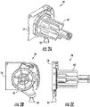
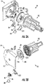
- the operating system 70 is shown in an exploded, subassembly view.
- the operating system 70 includes a base 74, a drive mechanism 78, a transmission 82, and a shift arm 86.
- the base 74, the drive mechanism 78, and the transmission 82 may be aligned along a common axis, which may be co-axial with a central axis of the rotatable member about which the covering 22 is wrapped.
- the shift arm 86 may be laterally offset from the common axis and may be movably disposed within a pocket 89 formed in a housing extension portion 91 formed within the base 74 near the periphery of the transmission 82.
- the shift arm 86 shifts the operating system 70 between the retraction and extension modes.
- the shift arm 86 selectively interacts with the transmission 82 to transition the operating system 70 between the retraction and extension modes as further described below.
- the housing extension portion 91 is illustrated as being integrally formed with the base 74, it is envisioned that the housing extension portion 91 may be separately formed and coupled thereto.
- the drive mechanism 78 may include a spool assembly having a spool 194 biased by a spool spring 198.
- the transmission 82 includes a clutch element 274, an axle 278, at least one wrap spring 282, a sun gear 286, a plurality of planet gears 290, an annulus or ring gear 294, a planet carrier 298, and a fastener 302.
- the components of the transmission 82 may be coaxially aligned with a post 114 extending from the base 74 ( FIG. 3A ).
- the transmission 82 may receive an input torque from the drive mechanism 78 and provide an output torque to the rotatable member.
- the transmission 82 may provide a gear reduction, such as by the example planetary gear system, to reduce the amount of input torque required to retract the covering 22.
- the transmission 82 may be disengaged from the other components of the operating system 70 so that the rotatable member can rotate in an extension or lowering direction via gravity.
- FIGS. 3A, 3B , and 5A -5D an example embodiment of a shift arm 86 of the operating system 70 is illustrated.
- the shift arm 86 selectively engages the transmission 82 to transition the operating system 70 between the retraction and extension modes.
- the shift arm 86 may be actuated by other means, for example, electrically.
- an operator moves the shift arm 86 between modes by manipulating the operating element 46 in predefined directions, such as, in a manner akin to a switch.
- Moving the operating element in a first direction shifts the operating system into the retraction mode
- moving the operating element in a second direction shifts the operating system into the extension mode.
- the first and second directions are transverse to a longitudinal axis of the architectural-structure covering.
- the operator may move the operating element 46 in a forward direction (e.g., towards the operator, in the direction indicated by the arrow 54C in FIG. IE) to move the shift arm 86 into a shade extension mode, thereby permitting the covering 22 to automatically extend or lower, such as by gravity.
- the shift arm 86 may be coupled to the base 74 of the operating system 70 adjacent the transmission 82. More specifically, the shift arm 86 may be movably (e.g., pivotably) coupled to the base 74 and positioned within a pocket 89 formed in a housing extension portion 91 extending from the base 74. In one implementation, the shift arm 86 may be constrained within a preset pivotable range, as will be described in greater detail below. In use, at one end of the pivot range, the shift arm 86 may contact the transmission 82 to substantially prevent rotation of the rotatable member in a shade extending direction, which may be referred to as the shade retraction mode for the sake of simplicity without the intent to limit. At the other end of the pivot range, the shift arm 86 may be disengaged from the transmission 82 to permit rotation of the rotatable member in the shade extension direction, which may be referred to as the shade extension mode for the sake of simplicity without the intent to limit.
- the shift arm 86 also includes one or more projections 518 ( FIGS. 5A and 5B ) for contacting and engaging to the transmission 82 when the shift arm 86 is in the shade retraction mode. That is, when the shift arm 86 is in the shade retraction mode, as shown in FIG. 9A , the projection 518 of the shift arm 86 may matingly engage (e.g., intermesh) with one or more projections 474 formed on the ring gear 294 to substantially prevent rotation of the ring gear 294. When the shift arm 86 is in the shade extension mode, as shown in FIG. 9B , the shift arm 86 may be pivoted away from the transmission 82 so that the projection 518 formed on the shift arm 86 is spatially separated from the projections 474 formed on the ring gear 294 to permit rotation of the ring gear 294.
- FIGS. 5A and 5B for contacting and engaging to the transmission 82 when the shift arm 86 is in the shade retraction mode. That is, when the shift arm 86 is in the
- the shift arm 86 may include a coupling arm 506 and a lever arm 510.
- the coupling arm 506 and the lever arm 510 may be formed so that they intersect with one another to form a generally right angle so that the in-out movement (movement of the operating element 46 towards and away from the operator) moves the coupling arm 506 into and out of engagement with the ring gear 294 as described above.
- the shift arm 86 may be generally L-shaped, although other shapes are envisioned.
- the shift arm 86 may further include a pathway or channel 525 formed in the proximal side thereof.
- the channel 525 may extend vertically through the post 494 thus subdividing the post 494 into first and second post members 494A, 494B.
- the channel 525 may further extend through the lever arm 510 and may terminate in an opening 542 ( FIG.5C ) such as, for example, an eyelet at the free end of the lever arm 510.
- the channel 525 and the opening (e.g., eyelet) 542 may be configured to accommodate the passage of the operating element 46 through the shift arm 86, with the operating element 46 passing through, or nearly through, the axis of the post 494 as illustrated in the cross-sectional view of the operating system 70 shown in FIG. 6 .
- the operating element 46 when the operating element 46 is manipulated (e.g., moved in a first or second direction (e.g., forward or rearward) via the operating element 46) during use of the operating system 70, the operating element 46 may move about the axis of the post 494 (or an axis near the axis of the post 494) and may move the lever arm 510, thereby causing the shift arm 86 to move about the axis of the post 494 into and out of contact with the ring gear 294.
- a first or second direction e.g., forward or rearward
- the operating system 70 may further include a removable cover 533 adapted to enclose the pocket 89 and the shift arm 86 within the pocket 89.
- the cover 533 may include one or more bosses, illustrated as first and second bosses 535, 537 that extend from the proximal side of the cover 533.
- the bosses 535, 537 being adapted to matingly engage corresponding mounting apertures 539, 541 formed in the distal side of the housing extension portion 91 of the base 74, illustrated in the front and rear walls 527, 529 of the pocket 89.
- the bosses 535, 537 may be held within the mounting apertures 539, 541 via any method now known or hereafter developed including, for example, via a friction fit, snap fit, etc. to removably couple the cover 533 to the base 74. It will be appreciated that the number of bosses and mounting apertures may be varied, and that additional or alternative mounting structures or configurations may be implemented for removably coupling the cover 533 to the base 74 without departing from the present disclosure.
- the pivot pin 543 may include a semicircular shape, although other shapes are envisioned including, but not limited to, a circular shape.
- the operating system 70 may include a detent to deter or prevent accidental or unintentional shifting between the retracted and extended configurations.
- the detent may be any now known or hereafter developed detent mechanism for preventing unwanted movement.
- the cover 533 and the shift arm 86 may include a detent to deter or prevent accidental or unintentional movement between the shift arm 86 and the ring gear 294.
- the cover 533 may further include a first magnet 545 located on or embedded in the proximal side thereof, and the shift arm 86 may include a second magnet 547 located on or embedded in the distal side thereof.
- the first and second magnets 545, 547 may have opposite polarities.
- the first magnet 545 may be disposed in close proximity to, and may partially overlap with, the second magnet 547.
- the first and second magnets 545, 547 may be of sufficient magnetic strength and may be disposed in sufficiently close proximity to each other so that the magnetic fields emanating from the first and second magnets 545, 547 may interact and palpably repel one another.
- the second magnet 547 may, depending on the position of the shift arm 86, be positioned left of a magnetic center of the first magnet 545 (as in FIG. 8A ) or right of the magnetic center the first magnet 545 (as in FIG. 8B ).
- the repelling magnetic force between the first and second magnets 545, 547 may act as a detent to maintain the shift arm 86 in a desired position until a sufficient manual force is applied to the lever arm 510 (e.g., via the operating element 46 by the operator) to overcome the repelling magnetic force and move or pivot the shift arm 86 to the opposite position.
- a sufficient manual force is applied to the lever arm 510 (e.g., via the operating element 46 by the operator) to overcome the repelling magnetic force and move or pivot the shift arm 86 to the opposite position.
- the second magnet 547 may be positioned left of the magnetic center of the first magnet 545, and the repelling magnetic force between the first and second magnets 545, 547 may therefore bias the shift arm 86 in the direction indicated by the arrow 549A, toward the retraction mode.
- an operator may manipulate the operating element 46 to, for example, pivot the lever arm 510 forward with a sufficient manual force to overcome the repelling magnetic force between the first and second magnets 545, 547 until the second magnet 547 has been moved past the magnetic center of the first magnet 545.
- the second magnet 547 may thereafter be repelled in the opposite direction indicated by the arrow 549B in FIG. 8B , pivotably biasing the shift arm 86 toward the extension mode.
- the repelling force between the first and second magnets 545, 547 may be sufficient to retain the shift arm 86 in the extension mode against the force of gravity acting on the shift arm 86, and the operating element 46 until a sufficient manual force is applied to the lever arm 510 (e.g., via the operating element 46) to overcome the repelling magnetic force and move the shift arm 86 to the retraction mode.
- the housing extension portion 91 has a lower surface 560 including a substantially planar first surface 562 and a substantially planar second surface 564 meeting at a curved juncture 566.
- the first surface 562 may be substantially horizontal, and an intersection of the plane of the first surface 562 and the plane of the second surface 564 defines an obtuse angle in a range of about 110 degrees to about 140 degrees, for example.
- the radius of curvature of the curved juncture 566 may be in a range from a sharp corner to about 8 millimeters, for example. In this manner, the curved juncture 566 obstructs forward movement of the operating element 46, and thus prevents the operating element 46 and hence the shift arm 86 from moving into the extension mode position accidentally via, for example, force of gravity without operator involvement.
- the operating element 46 when the operating element 46 is disposed in the retraction mode position as shown in FIG. 8A , the operating element 46 may be positioned along the first surface 562. While the operating element 46 is held thusly, the curved juncture 566 may obstruct forward movement of the operating element 46, and thus prevent the operating element 46 and hence the shift arm 86 from moving into the extension mode position accidentally via, for example, force of gravity without operator involvement. That is, the operator may, through the application of manual force, shift the operating element 46 forward, past the curved juncture 566, and into the extension mode position however, the curved junction 566 prevents or renders more difficult the unintentional movement of the operating element 46 and hence the shift arm 86 into the extension mode position. As such, the contour of the lower surface 560 of the housing extension portion 91 may act as a passive detent for maintaining the operating element 46 in the retraction mode position until it is desired to move the operating element 46 to the extension mode position, and vice-versa.
- the operating system 70 may be selectively switched between a retraction mode and an extension mode by manipulating the position of the shift arm 86.
- the operator may move the operating element 46 to transition the operating system 70 between the retraction mode and the extension mode, and vice-versa.
- the shift arm 86 in the retraction mode, the shift arm 86 is engaged with the ring gear 294 (e.g., projection 518 formed on the shift arm 86 engages or intermeshes with projections 474 formed on the ring gear 294 to prevent rotation and transfer of motion).
- the shift arm 86 may be disengaged from the ring gear 294.
- the operator moves the operating element 46 in a direction, for example, the first direction, generally rearward along the surface 560 of the housing extension portion 91. Since the operating element 46 is routed through the post 494, the lever arm 510, and the opening 542 of the shift arm 86, this rearward movement of the operating element 46 pivots or rotates the shift arm 86 radially towards the ring gear 294 into engagement therewith, placing the operating system 70 in the retraction mode.
- the operating system 70 permits the covering 22 to be raised or retracted.
- an operator pulls downward on the operating element 46. While pulling in a downward direction, the movement of the operating element 46 rotates the transmission 82, which rotates the rotatable member, causing the covering 22 to retract into the headrail.
- the clutch element 274 may selectively engage the sun gear 286 depending on the direction of rotation (e.g., during retraction, arms formed on the clutch element 274 may expand to engage an inner surface of the sun gear 286 while during extension, arms formed on the clutch element 274 may contract to disengage from the sun gear 286,).
- the ring gear 294 In the retraction mode, the ring gear 294 is prevented from rotating by the engagement of the shift arm 86 with the outwardly directed teeth 474 of the ring gear 294. With the ring gear 294 rotationally locked, rotation of the sun gear 286 causes the planet gears 290 to orbit around the sun gear 286, which in turn causes the planet carrier 298 to rotate. As the planet carrier 298 is coupled to the rotatable member, rotation of the planet carrier 298 rotates the rotatable member, retracting the covering 22. At the end of the downward stroke, the operator releases the operating element 46 and the spool spring 198 correspondingly reels in the operating element 46 around the groove 218 of the spool 194.
- the clutch element 274 isolates the sun gear 286 from the rotation of the spool 194. Additionally, the operating system 70 prevents the rotatable member from rotating in a shade extension direction, thereby maintaining the position of the covering 22 relative to the architectural opening during the intermittent retraction of the operating element 46.
- the sun gear 286 is rotationally locked to the stationary axle 278 in the shade extension direction by at least one wrap spring 282 and the ring gear 294 is rotationally locked by the shift arm 86.
- the sun gear 286 and the ring gear 294 prevent the planet gears 298 from orbiting about the sun gear 286, thereby inhibiting extension of the covering 22 across the opening when the operating system 70 is in the retraction mode.
- the operating system 70 holds the covering 22 in place. In this fashion, the operator can cyclically move the operating element 46 as many times as necessary to raise or retract the covering 22 a desired distance, causing the spool 194 to reciprocate rotationally back and forth and the sun gear 286 to incrementally advance forward in a winding direction.
- the operator moves the operating element 46 in a direction, for example, generally forward along the surface 560 of the housing extension portion 91.
- This movement of the operating element 46 transitions the operating system 70 from the retraction mode to the extension mode, and hence causes the shift arm 86 to move away from and thus to disengage from the ring gear 294.
- the operator may feel and/or hear an audible click as the ring gear 294 is released.
- the fixed orientation of the rotatable member may be released, allowing the covering 22 to unwind and lower by gravity or any other downward biasing element (such as, for example, a supplemental spring).
- any other downward biasing element such as, for example, a supplemental spring.
- the repelling magnetic force between the first and second magnets 545, 547, and/or the surface 560 of the housing extension portion 91 maintains the shift arm 86 in the shade extension mode, allowing the operator to release the operating element 46 and no longer monitor the architectural-structure covering 10 as the covering 22 is lowering.
- the covering 22 will lower regardless of handling nuances of the operator of the operating element 46, such as holding or releasing the operating element 46.
- the operator may shift the operating system 70 into the retraction mode by moving the shift arm 86 into engagement with the ring gear 294 (e.g., moving the operating element 46 in a direction generally rearward along the surface 560 of the housing extension portion 91).
Landscapes
- Engineering & Computer Science (AREA)
- Structural Engineering (AREA)
- Architecture (AREA)
- Civil Engineering (AREA)
- Arrangement Or Mounting Of Control Devices For Change-Speed Gearing (AREA)
- Operating, Guiding And Securing Of Roll- Type Closing Members (AREA)
- Transmission Devices (AREA)
- Specific Sealing Or Ventilating Devices For Doors And Windows (AREA)
Claims (11)
- Revêtement de structure architecturale (10) comprenant :une partie de revêtement (22) extensible et rétractable entre une position étendue et une position rétractée pour masquer et exposer une structure architecturale sous-jacente ;un élément rotatif autour duquel la partie de revêtement (22) ou des cordons de levage sont enroulés ou non enroulés, l'élément rotatif pouvant tourner autour d'un axe longitudinal dans une direction d'extension et une direction de rétraction ; etun système de fonctionnement (70) associé de manière fonctionnelle audit élément rotatif, le système de fonctionnement (70) comprenant :une transmission (82) pour transmettre sélectivement un couple d'entrée audit élément rotatif ;un bras de changement (86) pour engager sélectivement ladite transmission (82) pour faire passer ledit système de fonctionnement (70) entre un mode de rétraction pour rétracter ou soulever la partie de revêtement (22) et un mode d'extension pour étendre ou abaisser la partie de revêtement (22) ; etun élément d'actionnement (46) pour rétracter ou soulever la partie de revêtement (22) et pour commuter le système d'actionnement (70) entre ledit mode de rétraction et ledit mode d'extension, l'élément d'actionnement (46) pouvant être actionné pour fournir ledit couple d'entrée, et pour faire passer sélectivement ledit bras de changement (86) entre ledit mode de rétraction et ledit mode d'extension ;dans lequel ledit bras de changement (86) est mobile dans l'une d'une première direction et d'une seconde direction pour faire passer ledit système d'actionnement (70) entre ledit mode de rétraction et ledit mode d'extension ;dans lequel le bras de changement (86) comprend une ou plusieurs saillies (518) pour entrer en contact et s'engager avec la transmission (82) lorsque le bras de changement (86) est en mode de rétraction ; etdans lequel lesdites première et seconde directions sont transversales à un axe longitudinal du revêtement de structure architecturale (10), et dans lequel ladite première direction est l'une parmi une direction avant ou arrière, et ladite seconde direction est l'autre parmi une direction avant ou arrière ;dans lequel le revêtement comprend en outre une base (74), ledit bras de changement (86) étant couplé de manière pivotante à ladite base (74), caractérisé en ce que ladite base (74) comprend une partie d'extension de logement (91) qui a une surface inférieure (560) et une ouverture (531) traversant ladite surface inférieure (560), ladite surface inférieure (560) comprenant une première surface sensiblement plane (562), une seconde surface sensiblement plane (564) et une jonction incurvée (566) reliant lesdites première et seconde surfaces (562, 564), dans lequel la jonction incurvée est adaptée et configurée pour résister au mouvement de l'élément d'actionnement et une intersection du plan de la première surface et du plan de la seconde surface définit un angle obtus.
- Revêtement (10) selon la revendication 1, dans lequel, dans ledit mode de rétraction, ledit bras de changement (86) engage ladite transmission (82) pour empêcher la rotation dudit élément rotatif dans ladite direction d'extension.
- Revêtement (10) selon la revendication 2, dans lequel, dans ledit mode d'extension, ledit bras de changement (86) est désengagé de ladite transmission (82) pour permettre la rotation dudit élément rotatif dans ladite direction d'extension.
- Revêtement (10) selon l'une quelconque des revendications 1 à 3, dans lequel ladite transmission (82) comprend une couronne dentée (294) comprenant une ou plusieurs saillies (474), ladite saillie (518) étant formée sur ledit bras de changement (86) s'engrenant avec lesdites une ou plusieurs saillies (474) formées sur ladite couronne dentée (294) dans ledit mode de rétraction pour empêcher la rotation de ladite couronne dentée (294).
- Revêtement (10) selon la revendication 4, dans lequel, lorsque ledit bras de changement (86) est dans ledit mode d'extension, ladite saillie (518) formée sur ledit bras de changement (86) est espacée desdites une ou plusieurs saillies (474) formé sur ladite couronne dentée (294) pour permettre la rotation de ladite couronne dentée (294).
- Procédé de montée et descente d'une partie de revêtement (22) d'un revêtement de structure architecturale (10) selon l'une quelconque des revendications 1 à 5, le procédé comprenant :le déplacement de l'élément d'actionnement (46) associé au système de commande (70) du revêtement de structure architecturale (10) dans la première direction pour placer ledit système d'actionnement (70) dans le mode de rétraction pour soulever la partie de revêtement (22) à partir d'une position entièrement ou partiellement étendue ;le déplacement dudit élément d'actionnement (46) pour soulever la partie de revêtement (22) depuis ladite position entièrement ou partiellement étendue ; etle déplacement dudit élément d'actionnement (46) dans la seconde direction pour faire passer ledit système d'actionnement (70) dans le mode d'extension pour abaisser la partie de revêtement (22) à partir d'une position entièrement ou partiellement rétractée ;dans lequel lesdites première et seconde directions sont transversales à un axe longitudinal du revêtement de structure architecturale (10), et dans lequel ladite première direction est l'une parmi une direction avant ou arrière, et ladite seconde direction est l'autre parmi une direction avant ou arrière.
- Procédé selon la revendication 6, dans lequel dans ledit mode d'extension, la partie de revêtement (22) est étendue automatiquement par gravité.
- Procédé selon la revendication 6 ou 7, dans lequel, dans ledit mode de rétraction, la partie de revêtement (22) est soulevée via une pluralité de courses alternatives dudit élément d'actionnement (46).
- Procédé selon la revendication 8, comprenant en outre l'engagement d'un élément de frein pour empêcher l'extension de la partie de revêtement (22) entre lesdites courses alternatives.
- Procédé selon l'une quelconque des revendications 6 à 9, dans lequel le déplacement dudit élément d'actionnement (46) dans lesdites première et seconde directions commute sélectivement entre ledit mode de rétraction et ledit mode d'extension en manipulant une position d'un bras de changement (86) associé audit système de fonctionnement (70).
- Procédé selon la revendication 10, dans lequel le déplacement dudit élément d'actionnement (46) dans lesdites première et seconde directions déplace sélectivement ladite position dudit bras de changement (86) en engagement et hors engagement avec une partie d'une transmission (82) dudit système de fonctionnement (70).
Applications Claiming Priority (2)
| Application Number | Priority Date | Filing Date | Title |
|---|---|---|---|
| US201762565442P | 2017-09-29 | 2017-09-29 | |
| US201762570713P | 2017-10-11 | 2017-10-11 |
Publications (3)
| Publication Number | Publication Date |
|---|---|
| EP3461987A2 EP3461987A2 (fr) | 2019-04-03 |
| EP3461987A3 EP3461987A3 (fr) | 2019-06-26 |
| EP3461987B1 true EP3461987B1 (fr) | 2022-12-07 |
Family
ID=63678549
Family Applications (1)
| Application Number | Title | Priority Date | Filing Date |
|---|---|---|---|
| EP18196087.3A Active EP3461987B1 (fr) | 2017-09-29 | 2018-09-21 | Revêtement de structure architecturale |
Country Status (4)
| Country | Link |
|---|---|
| US (1) | US11136821B2 (fr) |
| EP (1) | EP3461987B1 (fr) |
| AU (1) | AU2018236810B2 (fr) |
| CA (1) | CA3017663A1 (fr) |
Families Citing this family (9)
| Publication number | Priority date | Publication date | Assignee | Title |
|---|---|---|---|---|
| KR102094570B1 (ko) * | 2013-03-11 | 2020-04-14 | 헌터더글라스인코포레이티드 | 건축물 개구부용 덮개를 위한 동작 시스템 |
| US10851587B2 (en) | 2016-10-19 | 2020-12-01 | Hunter Douglas Inc. | Motor assemblies for architectural coverings |
| CA3017663A1 (fr) * | 2017-09-29 | 2019-03-29 | Hunter Douglas Inc. | Systeme d'utilisation d'un revetement de structure architecturale |
| US11486198B2 (en) | 2019-04-19 | 2022-11-01 | Hunter Douglas Inc. | Motor assemblies for architectural coverings |
| JP7475234B2 (ja) * | 2020-07-29 | 2024-04-26 | トーソー株式会社 | 日射遮蔽装置及び日射遮蔽装置用の操作装置 |
| US11686151B2 (en) | 2020-12-31 | 2023-06-27 | Springs Window Fashions, Llc | Motorized shade and wand assembly |
| CA3266578A1 (fr) * | 2022-09-02 | 2024-03-07 | Hunter Douglas Inc. | Ensemble frein doté d'une roue libre pour un écran de structure architecturale |
| WO2024158567A1 (fr) | 2023-01-26 | 2024-08-02 | Hunter Douglas Inc. | Ensemble baguette destiné à être utilisé avec un système de cordon de tirage rétractable dans un dispositif de recouvrement de structure architecturale |
| CA3232918A1 (en) * | 2023-04-03 | 2025-06-23 | Rollease Acmeda, Inc. | Wand for a cord driven blind assembly |
Family Cites Families (28)
| Publication number | Priority date | Publication date | Assignee | Title |
|---|---|---|---|---|
| US1118033A (en) | 1912-10-30 | 1914-11-24 | Edward H Mccloud | Automatic fire-shutter. |
| US5848634A (en) | 1996-12-27 | 1998-12-15 | Latron Electronics Co. Inc. | Motorized window shade system |
| US6129131A (en) | 1997-11-26 | 2000-10-10 | Hunter Douglas Inc. | Control system for coverings for architectural openings |
| US7228797B1 (en) | 2000-11-28 | 2007-06-12 | Sundberg-Ferar, Inc. | Cordless blind |
| US7578334B2 (en) * | 2005-06-03 | 2009-08-25 | Hunter Douglas Inc. | Control system for architectural coverings with reversible drive and single operating element |
| US7128126B2 (en) * | 2003-03-04 | 2006-10-31 | Hunter Douglas Inc. | Control system for architectural coverings with reversible drive and single operating element |
| US7380582B1 (en) * | 2003-04-09 | 2008-06-03 | Hunter Douglas Inc. | Mounting arrangement for coverings for architectural openings |
| US7159635B2 (en) | 2003-06-25 | 2007-01-09 | Hunter Douglas Inc. | Lift cord spool for coverings for architectural openings |
| EP1644273B1 (fr) | 2003-07-16 | 2014-01-15 | Hunter Douglas Inc. | Dispositif d'entrainement de couvertures architecturales |
| EP2126265B1 (fr) * | 2007-01-29 | 2017-10-25 | Hunter Douglas Inc. | Système de commande pour couvertures architecturales à inversion de marche et un seul élément de commande |
| US20090120593A1 (en) | 2007-11-14 | 2009-05-14 | Hunter Douglas Inc. | Control unit for lift system for coverings for architectural openings |
| US8522854B2 (en) | 2011-07-25 | 2013-09-03 | Shih-Ming Lin | Operating device for rotating a winding roller of a window blind |
| WO2013027878A1 (fr) * | 2011-08-25 | 2013-02-28 | Kim Jung-Min | Store roulant pourvu d'un cordon de sécurité unique |
| TWI604124B (zh) | 2012-02-23 | 2017-11-01 | 德侑股份有限公司 | 窗簾及其控制模組 |
| WO2014034971A1 (fr) | 2012-08-28 | 2014-03-06 | Kim Jung Min | Store déroulant comportant un cordon de commande unique |
| US20140166218A1 (en) * | 2012-12-13 | 2014-06-19 | Philip Ng | Chain Guide for Dual Roller Blind |
| KR102094570B1 (ko) | 2013-03-11 | 2020-04-14 | 헌터더글라스인코포레이티드 | 건축물 개구부용 덮개를 위한 동작 시스템 |
| CN104274053B (zh) | 2013-07-05 | 2016-12-07 | 德侑股份有限公司 | 窗帘、其操控系统及操作方法 |
| US10519713B2 (en) * | 2015-07-01 | 2019-12-31 | Hunter Douglas Inc. | Static mitigation end cap for a covering for an architectural opening |
| US10544621B2 (en) * | 2015-08-31 | 2020-01-28 | Sun Glow Window Covering Products of Canada Ltd. | Roller shade system |
| US10655385B2 (en) * | 2016-02-19 | 2020-05-19 | Hunter Douglas Inc. | Dual cord operating system for an architectural covering |
| US10538963B2 (en) * | 2016-02-19 | 2020-01-21 | Hunter Douglas Inc | Wand for architectural covering |
| NL2016447B1 (nl) * | 2016-03-17 | 2017-10-05 | Coulisse Bv | Inrichting voor het handmatig bedienen van een gemotoriseerde aandrijving van een scherm, zoals een raambekleding en werkwijze voor het opslaan van instelwaarden behorende bij verschillende posities van het scherm |
| US10851587B2 (en) * | 2016-10-19 | 2020-12-01 | Hunter Douglas Inc. | Motor assemblies for architectural coverings |
| US10407983B2 (en) * | 2016-10-26 | 2019-09-10 | Hunter Douglas Inc. | Operating system for an architectural covering |
| US10847983B2 (en) * | 2017-04-17 | 2020-11-24 | Nien Made Enterprise Co., Ltd. | Charging system for electric window covering and method of charging electric window covering with the same |
| CA3017663A1 (fr) * | 2017-09-29 | 2019-03-29 | Hunter Douglas Inc. | Systeme d'utilisation d'un revetement de structure architecturale |
| US11486198B2 (en) * | 2019-04-19 | 2022-11-01 | Hunter Douglas Inc. | Motor assemblies for architectural coverings |
-
2018
- 2018-09-18 CA CA3017663A patent/CA3017663A1/fr active Pending
- 2018-09-20 US US16/136,470 patent/US11136821B2/en active Active
- 2018-09-21 EP EP18196087.3A patent/EP3461987B1/fr active Active
- 2018-09-27 AU AU2018236810A patent/AU2018236810B2/en active Active
Also Published As
| Publication number | Publication date |
|---|---|
| US20190100962A1 (en) | 2019-04-04 |
| EP3461987A3 (fr) | 2019-06-26 |
| CA3017663A1 (fr) | 2019-03-29 |
| US11136821B2 (en) | 2021-10-05 |
| AU2018236810A1 (en) | 2019-04-18 |
| AU2018236810B2 (en) | 2024-08-22 |
| EP3461987A2 (fr) | 2019-04-03 |
Similar Documents
| Publication | Publication Date | Title |
|---|---|---|
| EP3461987B1 (fr) | Revêtement de structure architecturale | |
| US12116841B2 (en) | Operating system for a covering for an architectural opening | |
| KR101541393B1 (ko) | 역작동가능한 드라이브 및 단일 작동 요소를 갖는 건축물 커버링 용 제어시스템 | |
| JP7007853B2 (ja) | 建築カバー用操作システム | |
| RU2585554C1 (ru) | Оконная штора, ее модуль управления и ее способ работы | |
| KR102089142B1 (ko) | 윈도우 쉐이드 | |
| AU2019213349B2 (en) | Operating Mechanism for a Covering for an Architectural Opening | |
| JP6728126B2 (ja) | 建築物開口部用の覆いのためのオペレーティングシステム |
Legal Events
| Date | Code | Title | Description |
|---|---|---|---|
| PUAI | Public reference made under article 153(3) epc to a published international application that has entered the european phase |
Free format text: ORIGINAL CODE: 0009012 |
|
| STAA | Information on the status of an ep patent application or granted ep patent |
Free format text: STATUS: THE APPLICATION HAS BEEN PUBLISHED |
|
| AK | Designated contracting states |
Kind code of ref document: A2 Designated state(s): AL AT BE BG CH CY CZ DE DK EE ES FI FR GB GR HR HU IE IS IT LI LT LU LV MC MK MT NL NO PL PT RO RS SE SI SK SM TR |
|
| AX | Request for extension of the european patent |
Extension state: BA ME |
|
| PUAL | Search report despatched |
Free format text: ORIGINAL CODE: 0009013 |
|
| AK | Designated contracting states |
Kind code of ref document: A3 Designated state(s): AL AT BE BG CH CY CZ DE DK EE ES FI FR GB GR HR HU IE IS IT LI LT LU LV MC MK MT NL NO PL PT RO RS SE SI SK SM TR |
|
| AX | Request for extension of the european patent |
Extension state: BA ME |
|
| RIC1 | Information provided on ipc code assigned before grant |
Ipc: E06B 9/24 20060101ALN20190523BHEP Ipc: E06B 9/34 20060101AFI20190523BHEP |
|
| STAA | Information on the status of an ep patent application or granted ep patent |
Free format text: STATUS: REQUEST FOR EXAMINATION WAS MADE |
|
| 17P | Request for examination filed |
Effective date: 20191223 |
|
| RBV | Designated contracting states (corrected) |
Designated state(s): AL AT BE BG CH CY CZ DE DK EE ES FI FR GB GR HR HU IE IS IT LI LT LU LV MC MK MT NL NO PL PT RO RS SE SI SK SM TR |
|
| TPAC | Observations filed by third parties |
Free format text: ORIGINAL CODE: EPIDOSNTIPA |
|
| STAA | Information on the status of an ep patent application or granted ep patent |
Free format text: STATUS: EXAMINATION IS IN PROGRESS |
|
| 17Q | First examination report despatched |
Effective date: 20210615 |
|
| RIC1 | Information provided on ipc code assigned before grant |
Ipc: E06B 9/90 20060101ALN20220602BHEP Ipc: E06B 9/24 20060101ALN20220602BHEP Ipc: E06B 9/78 20060101ALI20220602BHEP Ipc: E06B 9/42 20060101ALI20220602BHEP Ipc: E06B 9/322 20060101ALI20220602BHEP Ipc: E06B 9/34 20060101AFI20220602BHEP |
|
| GRAP | Despatch of communication of intention to grant a patent |
Free format text: ORIGINAL CODE: EPIDOSNIGR1 |
|
| STAA | Information on the status of an ep patent application or granted ep patent |
Free format text: STATUS: GRANT OF PATENT IS INTENDED |
|
| INTG | Intention to grant announced |
Effective date: 20220708 |
|
| GRAS | Grant fee paid |
Free format text: ORIGINAL CODE: EPIDOSNIGR3 |
|
| GRAA | (expected) grant |
Free format text: ORIGINAL CODE: 0009210 |
|
| STAA | Information on the status of an ep patent application or granted ep patent |
Free format text: STATUS: THE PATENT HAS BEEN GRANTED |
|
| AK | Designated contracting states |
Kind code of ref document: B1 Designated state(s): AL AT BE BG CH CY CZ DE DK EE ES FI FR GB GR HR HU IE IS IT LI LT LU LV MC MK MT NL NO PL PT RO RS SE SI SK SM TR |
|
| REG | Reference to a national code |
Ref country code: GB Ref legal event code: FG4D |
|
| REG | Reference to a national code |
Ref country code: CH Ref legal event code: EP Ref country code: AT Ref legal event code: REF Ref document number: 1536407 Country of ref document: AT Kind code of ref document: T Effective date: 20221215 |
|
| REG | Reference to a national code |
Ref country code: DE Ref legal event code: R096 Ref document number: 602018043907 Country of ref document: DE |
|
| REG | Reference to a national code |
Ref country code: IE Ref legal event code: FG4D |
|
| REG | Reference to a national code |
Ref country code: NL Ref legal event code: FP |
|
| REG | Reference to a national code |
Ref country code: LT Ref legal event code: MG9D |
|
| PG25 | Lapsed in a contracting state [announced via postgrant information from national office to epo] |
Ref country code: SE Free format text: LAPSE BECAUSE OF FAILURE TO SUBMIT A TRANSLATION OF THE DESCRIPTION OR TO PAY THE FEE WITHIN THE PRESCRIBED TIME-LIMIT Effective date: 20221207 Ref country code: NO Free format text: LAPSE BECAUSE OF FAILURE TO SUBMIT A TRANSLATION OF THE DESCRIPTION OR TO PAY THE FEE WITHIN THE PRESCRIBED TIME-LIMIT Effective date: 20230307 Ref country code: LT Free format text: LAPSE BECAUSE OF FAILURE TO SUBMIT A TRANSLATION OF THE DESCRIPTION OR TO PAY THE FEE WITHIN THE PRESCRIBED TIME-LIMIT Effective date: 20221207 Ref country code: FI Free format text: LAPSE BECAUSE OF FAILURE TO SUBMIT A TRANSLATION OF THE DESCRIPTION OR TO PAY THE FEE WITHIN THE PRESCRIBED TIME-LIMIT Effective date: 20221207 Ref country code: ES Free format text: LAPSE BECAUSE OF FAILURE TO SUBMIT A TRANSLATION OF THE DESCRIPTION OR TO PAY THE FEE WITHIN THE PRESCRIBED TIME-LIMIT Effective date: 20221207 |
|
| REG | Reference to a national code |
Ref country code: AT Ref legal event code: MK05 Ref document number: 1536407 Country of ref document: AT Kind code of ref document: T Effective date: 20221207 |
|
| PG25 | Lapsed in a contracting state [announced via postgrant information from national office to epo] |
Ref country code: RS Free format text: LAPSE BECAUSE OF FAILURE TO SUBMIT A TRANSLATION OF THE DESCRIPTION OR TO PAY THE FEE WITHIN THE PRESCRIBED TIME-LIMIT Effective date: 20221207 Ref country code: PL Free format text: LAPSE BECAUSE OF FAILURE TO SUBMIT A TRANSLATION OF THE DESCRIPTION OR TO PAY THE FEE WITHIN THE PRESCRIBED TIME-LIMIT Effective date: 20221207 Ref country code: LV Free format text: LAPSE BECAUSE OF FAILURE TO SUBMIT A TRANSLATION OF THE DESCRIPTION OR TO PAY THE FEE WITHIN THE PRESCRIBED TIME-LIMIT Effective date: 20221207 Ref country code: HR Free format text: LAPSE BECAUSE OF FAILURE TO SUBMIT A TRANSLATION OF THE DESCRIPTION OR TO PAY THE FEE WITHIN THE PRESCRIBED TIME-LIMIT Effective date: 20221207 Ref country code: GR Free format text: LAPSE BECAUSE OF FAILURE TO SUBMIT A TRANSLATION OF THE DESCRIPTION OR TO PAY THE FEE WITHIN THE PRESCRIBED TIME-LIMIT Effective date: 20230308 |
|
| P01 | Opt-out of the competence of the unified patent court (upc) registered |
Effective date: 20230512 |
|
| PG25 | Lapsed in a contracting state [announced via postgrant information from national office to epo] |
Ref country code: SM Free format text: LAPSE BECAUSE OF FAILURE TO SUBMIT A TRANSLATION OF THE DESCRIPTION OR TO PAY THE FEE WITHIN THE PRESCRIBED TIME-LIMIT Effective date: 20221207 Ref country code: RO Free format text: LAPSE BECAUSE OF FAILURE TO SUBMIT A TRANSLATION OF THE DESCRIPTION OR TO PAY THE FEE WITHIN THE PRESCRIBED TIME-LIMIT Effective date: 20221207 Ref country code: PT Free format text: LAPSE BECAUSE OF FAILURE TO SUBMIT A TRANSLATION OF THE DESCRIPTION OR TO PAY THE FEE WITHIN THE PRESCRIBED TIME-LIMIT Effective date: 20230410 Ref country code: EE Free format text: LAPSE BECAUSE OF FAILURE TO SUBMIT A TRANSLATION OF THE DESCRIPTION OR TO PAY THE FEE WITHIN THE PRESCRIBED TIME-LIMIT Effective date: 20221207 Ref country code: CZ Free format text: LAPSE BECAUSE OF FAILURE TO SUBMIT A TRANSLATION OF THE DESCRIPTION OR TO PAY THE FEE WITHIN THE PRESCRIBED TIME-LIMIT Effective date: 20221207 Ref country code: AT Free format text: LAPSE BECAUSE OF FAILURE TO SUBMIT A TRANSLATION OF THE DESCRIPTION OR TO PAY THE FEE WITHIN THE PRESCRIBED TIME-LIMIT Effective date: 20221207 |
|
| PG25 | Lapsed in a contracting state [announced via postgrant information from national office to epo] |
Ref country code: SK Free format text: LAPSE BECAUSE OF FAILURE TO SUBMIT A TRANSLATION OF THE DESCRIPTION OR TO PAY THE FEE WITHIN THE PRESCRIBED TIME-LIMIT Effective date: 20221207 Ref country code: IS Free format text: LAPSE BECAUSE OF FAILURE TO SUBMIT A TRANSLATION OF THE DESCRIPTION OR TO PAY THE FEE WITHIN THE PRESCRIBED TIME-LIMIT Effective date: 20230407 Ref country code: AL Free format text: LAPSE BECAUSE OF FAILURE TO SUBMIT A TRANSLATION OF THE DESCRIPTION OR TO PAY THE FEE WITHIN THE PRESCRIBED TIME-LIMIT Effective date: 20221207 |
|
| REG | Reference to a national code |
Ref country code: DE Ref legal event code: R097 Ref document number: 602018043907 Country of ref document: DE |
|
| PLBE | No opposition filed within time limit |
Free format text: ORIGINAL CODE: 0009261 |
|
| STAA | Information on the status of an ep patent application or granted ep patent |
Free format text: STATUS: NO OPPOSITION FILED WITHIN TIME LIMIT |
|
| PG25 | Lapsed in a contracting state [announced via postgrant information from national office to epo] |
Ref country code: DK Free format text: LAPSE BECAUSE OF FAILURE TO SUBMIT A TRANSLATION OF THE DESCRIPTION OR TO PAY THE FEE WITHIN THE PRESCRIBED TIME-LIMIT Effective date: 20221207 |
|
| 26N | No opposition filed |
Effective date: 20230908 |
|
| PG25 | Lapsed in a contracting state [announced via postgrant information from national office to epo] |
Ref country code: SI Free format text: LAPSE BECAUSE OF FAILURE TO SUBMIT A TRANSLATION OF THE DESCRIPTION OR TO PAY THE FEE WITHIN THE PRESCRIBED TIME-LIMIT Effective date: 20221207 |
|
| REG | Reference to a national code |
Ref country code: CH Ref legal event code: PL |
|
| PG25 | Lapsed in a contracting state [announced via postgrant information from national office to epo] |
Ref country code: LU Free format text: LAPSE BECAUSE OF NON-PAYMENT OF DUE FEES Effective date: 20230921 |
|
| PG25 | Lapsed in a contracting state [announced via postgrant information from national office to epo] |
Ref country code: LU Free format text: LAPSE BECAUSE OF NON-PAYMENT OF DUE FEES Effective date: 20230921 Ref country code: IT Free format text: LAPSE BECAUSE OF FAILURE TO SUBMIT A TRANSLATION OF THE DESCRIPTION OR TO PAY THE FEE WITHIN THE PRESCRIBED TIME-LIMIT Effective date: 20221207 Ref country code: MC Free format text: LAPSE BECAUSE OF FAILURE TO SUBMIT A TRANSLATION OF THE DESCRIPTION OR TO PAY THE FEE WITHIN THE PRESCRIBED TIME-LIMIT Effective date: 20221207 |
|
| REG | Reference to a national code |
Ref country code: IE Ref legal event code: MM4A |
|
| PG25 | Lapsed in a contracting state [announced via postgrant information from national office to epo] |
Ref country code: IE Free format text: LAPSE BECAUSE OF NON-PAYMENT OF DUE FEES Effective date: 20230921 |
|
| PG25 | Lapsed in a contracting state [announced via postgrant information from national office to epo] |
Ref country code: CH Free format text: LAPSE BECAUSE OF NON-PAYMENT OF DUE FEES Effective date: 20230930 |
|
| PG25 | Lapsed in a contracting state [announced via postgrant information from national office to epo] |
Ref country code: IE Free format text: LAPSE BECAUSE OF NON-PAYMENT OF DUE FEES Effective date: 20230921 Ref country code: FR Free format text: LAPSE BECAUSE OF NON-PAYMENT OF DUE FEES Effective date: 20230930 Ref country code: CH Free format text: LAPSE BECAUSE OF NON-PAYMENT OF DUE FEES Effective date: 20230930 |
|
| PG25 | Lapsed in a contracting state [announced via postgrant information from national office to epo] |
Ref country code: BG Free format text: LAPSE BECAUSE OF FAILURE TO SUBMIT A TRANSLATION OF THE DESCRIPTION OR TO PAY THE FEE WITHIN THE PRESCRIBED TIME-LIMIT Effective date: 20221207 |
|
| PG25 | Lapsed in a contracting state [announced via postgrant information from national office to epo] |
Ref country code: BG Free format text: LAPSE BECAUSE OF FAILURE TO SUBMIT A TRANSLATION OF THE DESCRIPTION OR TO PAY THE FEE WITHIN THE PRESCRIBED TIME-LIMIT Effective date: 20221207 |
|
| PG25 | Lapsed in a contracting state [announced via postgrant information from national office to epo] |
Ref country code: CY Free format text: LAPSE BECAUSE OF FAILURE TO SUBMIT A TRANSLATION OF THE DESCRIPTION OR TO PAY THE FEE WITHIN THE PRESCRIBED TIME-LIMIT; INVALID AB INITIO Effective date: 20180921 |
|
| PG25 | Lapsed in a contracting state [announced via postgrant information from national office to epo] |
Ref country code: HU Free format text: LAPSE BECAUSE OF FAILURE TO SUBMIT A TRANSLATION OF THE DESCRIPTION OR TO PAY THE FEE WITHIN THE PRESCRIBED TIME-LIMIT; INVALID AB INITIO Effective date: 20180921 |
|
| PGFP | Annual fee paid to national office [announced via postgrant information from national office to epo] |
Ref country code: DE Payment date: 20250926 Year of fee payment: 8 |
|
| PGFP | Annual fee paid to national office [announced via postgrant information from national office to epo] |
Ref country code: NL Payment date: 20250925 Year of fee payment: 8 |
|
| PGFP | Annual fee paid to national office [announced via postgrant information from national office to epo] |
Ref country code: BE Payment date: 20250925 Year of fee payment: 8 Ref country code: GB Payment date: 20250923 Year of fee payment: 8 |
|
| PG25 | Lapsed in a contracting state [announced via postgrant information from national office to epo] |
Ref country code: TR Free format text: LAPSE BECAUSE OF FAILURE TO SUBMIT A TRANSLATION OF THE DESCRIPTION OR TO PAY THE FEE WITHIN THE PRESCRIBED TIME-LIMIT Effective date: 20221207 |