EP3462070B1 - Lösbare verbindung - Google Patents
Lösbare verbindung Download PDFInfo
- Publication number
- EP3462070B1 EP3462070B1 EP18197660.6A EP18197660A EP3462070B1 EP 3462070 B1 EP3462070 B1 EP 3462070B1 EP 18197660 A EP18197660 A EP 18197660A EP 3462070 B1 EP3462070 B1 EP 3462070B1
- Authority
- EP
- European Patent Office
- Prior art keywords
- fitting element
- fitting
- annular
- annular body
- elastic ring
- Prior art date
- Legal status (The legal status is an assumption and is not a legal conclusion. Google has not performed a legal analysis and makes no representation as to the accuracy of the status listed.)
- Active
Links
Images



Classifications
-
- F—MECHANICAL ENGINEERING; LIGHTING; HEATING; WEAPONS; BLASTING
- F16—ENGINEERING ELEMENTS AND UNITS; GENERAL MEASURES FOR PRODUCING AND MAINTAINING EFFECTIVE FUNCTIONING OF MACHINES OR INSTALLATIONS; THERMAL INSULATION IN GENERAL
- F16L—PIPES; JOINTS OR FITTINGS FOR PIPES; SUPPORTS FOR PIPES, CABLES OR PROTECTIVE TUBING; MEANS FOR THERMAL INSULATION IN GENERAL
- F16L37/00—Couplings of the quick-acting type
- F16L37/08—Couplings of the quick-acting type in which the connection between abutting or axially overlapping ends is maintained by locking members
- F16L37/084—Couplings of the quick-acting type in which the connection between abutting or axially overlapping ends is maintained by locking members combined with automatic locking
- F16L37/088—Couplings of the quick-acting type in which the connection between abutting or axially overlapping ends is maintained by locking members combined with automatic locking by means of a split elastic ring
Definitions
- the invention relates to a releasable fitting, in particular a fitting with quick coupling and uncoupling of the "push-to-connect" type.
- the invention can be used for connecting two hydraulic items in hydraulic applications.
- EP 1 770 320 A1 discloses a releasable fitting comprising tubular first and second elements, sealing means, an annular body and an elastic ring.
- One object of the invention is to make a releasable fitting that is able to overcome the aforesaid problem of the prior art.
- One advantage is to give rise to a releasable fitting that protects against the risk of accidental uncoupling due to human error.
- One advantage is to provide a fitting with quick coupling and uncoupling of the "push to connect" type, of easy, practical, rapid and immediate use, both in the insertion step and in the extraction step.
- One advantage is to provide a releasable fitting of significant reliability and toughness, which is in particular usable in hydraulic applications.
- One advantage is to make available a releasable fitting of the "push to connect" type that is constructionally simple and cheap.
- One advantage is to prevent manual uncoupling of the fitting in the presence of pressurized fluid inside the fitting, or at least when the inner pressure of the fluid exceeds threshold values that may be relatively low (and depend on the dimensions of the fitting).
- a releasable fitting comprises a female element, a male element that is insertable into and extractable from the female element, an annular body that is slidable inside the fitting, elastic means for pressing the annular body against the female element, an elastic coupling ring pressed between the annular body and the male element, in which a thrust on the male element causes a movement of the annular body with respect to the female element generating a free space comprised between the annular body and the female element, in which an opening obtained on the female element enables an external tool to be introduced into this free space that can block the annular body in position during extraction of the male element.
- a releasable fitting of the "push-to-connect" type has been indicated in which coupling is achieved by inserting axially a (male) fitting element that is pushed inside another (female) fitting element.
- the uncoupling operation comprises a step in which a (male) fitting element is pushed axially inside, performing a first initial pre-uncoupling stroke that enables this fitting element to be subsequently extracted axially towards the exterior.
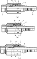
- the releasable fitting 1 may comprise, in particular, a first fitting element 2, or female fitting element, of tubular shape, which defines a coupling axis of the fitting 1.
- the first fitting element 2 may comprise, in particular, at least one inner sealing surface 3 (of cylindrical shape).
- the first fitting element 2 may comprise, in particular, at least one tubular portion 4 that has one or more through radial openings 5. It is possible to provide, as in the specific embodiment, a plurality of radial openings 5 arranged in a crown on the tubular portion 4 around the aforesaid coupling axis.
- the first fitting element 2 may comprise, in particular, at least one closure portion 6 of annular shape that protrudes radially inside from the tubular portion 4.
- the first fitting element 2 may be provided, as in this embodiment, with an end portion 7 intended for connection (for example of screw type) with a first hydraulic device (not illustrated).
- the first fitting element 2 may be made, as in this embodiment, in at least two distinct pieces (in particular two pieces made of metal, for example of steel), in which a first piece may comprise the tubular portion 4 and a second piece may comprise the closure portion 6.
- the two pieces may be fitted to one another, for example by a fixing ring 8.
- the releasable fitting may comprise, in particular, a second fitting element 9, or male fitting element, of tubular shape, which is couplable with the first fitting element 2 along the aforesaid coupling axis.
- the second fitting element 9 may be provided, as in this embodiment, with an end portion 10 intended for connecting with a second hydraulic device (not illustrated).
- the second fitting element 9 may comprise, in particular, at least one outer sealing surface 11 (of cylindrical shape).
- the second fitting element 9 may be at least partially insertable axially into the first fitting element 2 in an axial insertion direction so as to couple the outer sealing surface 11 with the inner sealing surface 3.
- the second fitting element 9 may be extractable axially from the first fitting element 2 in an axial extraction direction opposite the insertion direction.
- the second fitting element 9 may be made, as in this embodiment, of a single piece.
- the second fitting element 9 may comprise, in particular, an outer surface 12 (for example at least partially of cylindrical shape), which may have, as in this embodiment, a diameter that is greater than the outer sealing surface 11.
- the second fitting element 9 may comprise, in particular, at least one annular recess 13 that recedes radially to the inside from the outer surface 12, in particular to house a coupling elastic ring 14, as will be explained better below.
- the releasable fitting may comprise, in particular, sealing means 15 (for example at least one sealing ring) arranged between the outer sealing surface 11 and the inner sealing surface 3 when the second (male) fitting element 9 is coupled with the first (female) fitting element 2.
- sealing means 15 for example at least one sealing ring
- the releasable fitting may comprise, in particular, an annular body 16 that may slide axially with respect to at least the first fitting element 2.
- the annular body 16 may be surrounded at least partially by at least one part of the tubular portion 4 of the first fitting element 2.
- the annular body 16 may slide axially with the possibility of adopting at least one abutting position (see Figures 1 , 4 , 5 and 6 ) in which it abuts against the first fitting element 2 (in an abutment direction that is the same as the extraction direction of the second fitting element 9 from the first fitting element 2).
- the annular body 16 may comprise, in particular, an inner surface 17 (for example at least partially of cylindrical shape) with a diameter that is greater than the outer surface 12 of the second fitting element 9.
- the annular body 16 may comprise, in particular, an annular projection 18 that protrudes radially inside from the inner surface 17.
- the annular projection 18 may perform the function of exerting radial pressure on the coupling elastic ring 14 housed in the annular recess 13 to lock in position the second fitting element 9 and prevent the axial extraction thereof in the extraction direction, as will be explained better below.
- the inner surface 17 of the annular body 16 may have, as in this embodiment, two annular portions 17a and 17b that are adjacent to the annular projection 18 and are arranged on two opposite sides of the annular projection 18 in an axial direction, one adjacent on one side of the annular projection 18 and the other adjacent on the opposite side.
- Each annular portion 17a and 17b may have an inner diameter that is greater than an inner diameter of the annular projection 18.
- Each annular portion 17a and 17b is configured for temporarily housing the coupling elastic ring 14 (in an enlarged configuration) during the transitional steps of insertion and/or extraction of the second fitting element 9, as will be explained better below.
- the annular body 16 may comprise, in particular, a disengagement end 19.
- the disengagement end 19 When the annular body 16 is in the abutting position, the disengagement end 19 may be in a proximal position (for example in contact or, as in this embodiment, at a relatively reduced non nil distance) with respect to the closure portion 6 of the first fitting element 2.
- the annular projection 18 may be, as in this embodiment, arranged abutting against the closure portion 6. In other embodiments which are not illustrated, it is possible to provide for the disengagement end 19 rather than the annular projection 18 abutting against the closure portion 6.
- the releasable fitting may comprise, in particular, elastic means 20 (for example a coil spring) arranged for exerting an axial force on the annular body 16 in the extraction direction, in such a manner as to maintain the annular body 16 in the abutting position (abutting against the closure portion 6).
- elastic means 20 for example a coil spring
- the releasable fitting may comprise, in particular, the coupling elastic ring 14 that, when the second fitting element 9 is inserted into the first fitting element 2 and the annular body 16 is in the abutting position, may be arranged between the inner surface 17 of the annular body 16 and the outer surface 12 of the second fitting element 9.
- the elastic ring 14 is configured for being housed in the annular recess 13 and may be pressed radially by the annular projection 18, to ensure fitted coupling between the two fitting elements 2 and 9.
- the elastic ring 14 may be made, for example, of steel for springs.
- the elastic ring 14 may be contained, as in this embodiment, in an axial direction, on both sides.
- the elastic ring 14 may be contained on one side by the closure portion 6 of the first fitting element 2 and on the opposite side by a shoulder 21 of the annular body, in particular a shoulder 21 that may be arranged adjacent to the inner surface 17 of the annular body 16.
- the releasable fitting may adopt a coupling configuration in which the sealing means 15 is operational between the outer sealing surface 11 and the inner sealing surface 3.
- the annular body 16 may be in the abutting position and the elastic ring 14 may be housed in the annular recess 13 and be pressed radially by the annular projection 18.
- the second fitting element 9 may perform a pre-uncoupling axial movement with respect to the first fitting element 2, so that the second fitting element 9 may be pushed into the insertion direction, from the coupling configuration, to perform a short stroke (i.e. the aforesaid axial pre-uncoupling movement) directed inside the fitting (i.e. in the insertion direction) to disengage the elastic ring 14 from the annular projection 18, i.e. removing the radial pressure on the elastic ring 14.
- a short stroke i.e. the aforesaid axial pre-uncoupling movement directed inside the fitting (i.e. in the insertion direction) to disengage the elastic ring 14 from the annular projection 18, i.e. removing the radial pressure on the elastic ring 14.
- the annular body 16 may be movable axially with respect to the first fitting element 2 in the insertion direction, starting from the abutting position, so as to move the disengagement end 19 to a distal position with respect to the closure portion 6, i.e. by increasing the axial distance of the disengagement end 19 from the closure portion 6.
- the second fitting element 9 may be provided with a thrust surface 22 intended to go against the annular body 16 whilst the second fitting element 9 performs the aforesaid pre-uncoupling movement, such that this thrust surface 22 first comes to abut against the annular body 16 and then pushes the movable annular body 16 in the insertion direction, from the abutting position to a pre-uncoupling position (see Figure 7 ) in which the disengagement end 19 is in the aforesaid distal position and in which a free space is defined that is comprised axially between the disengagement end 19 and the closure portion 6.
- the disengagement end 19 is freely accessible from the exterior through at least one of the radial openings 5 obtained on the tubular portion 4 of the first fitting element 2, to enable an outer tool T to be introduced inside this free space, (for example a usual screwdriver) that can interact with the disengagement end 19 (for example by pointing an end of the tool T against the disengagement end 19 and levering on an edge of the radial opening 5) to prevent an axial movement of the annular body 16 in the extraction direction, such that the second fitting element 9 can be safely extracted axially in the extraction direction.
- an outer tool T for example a usual screwdriver
- Each radial opening 5 may be arranged on the tubular portion 4 so that, in the aforesaid abutting position, the radial opening 5 is closed internally by the annular body 16.
- the disengagement end 19 may be closed all around laterally by the tubular portion 4 and may be closed frontally by the closure portion 6, in order to prevent access to the disengagement end 19 from the exterior, unless when the annular body 16 is moved away from the closure portion 6 during the pre-uncoupling step, generating the free space disclosed above.
- the second fitting element 9 may comprise, as in this embodiment, a tapered surface 23 (for example of frustoconical shape) arranged between the annular recess 13 and the thrust surface 22.
- the tapered surface 23 may be intended to interact in contact with the elastic ring 14 in a step of axial insertion of the second fitting element 9 inside the first fitting element 2, to promote widening of the elastic ring 14 and the subsequent housing of the elastic ring 14 inside the annular recess 13.
- the annular body 16 interacting in contact, in an axial direction, with a stop surface 24 arranged on the first fitting element 2.
- the annular body 16 comprises a portion, for example a flanged portion 25, axially interposed between the stop surface 24 of the first fitting element 2 and the thrust surface 22 of the second fitting element 9.
- This stop surface 24 may be arranged, in particular, on a first shoulder of the first fitting element 2.
- the thrust surface 22 may be arranged, in particular, on a second shoulder of the second fitting element 9.
- the flanged portion 25 is spaced axially apart from the aforesaid first shoulder on one side and from the aforesaid second shoulder on the opposite side. It is possible to provide other embodiments which are not illustrated, in which the annular body 16 is not provided with the flanged portion 25.
- the second fitting element 9 (male element) is inserted inside the first fitting element 2 (female element), for example by an axial thrust force that may be exerted (manually) by an operator carrying the second fitting element 9.
- the second fitting element 9 meets the elastic ring 14, in particular the tapered surface 23 meets the elastic ring 14 and widens the elastic ring 14 gradually by moving the elastic ring 14 from the annular projection 18 until it abuts on the shoulder 21 of the annular body 16.
- the elastic ring 14 is radially at an annular portion 17a of inner surface 17 adjacent to the annular projection 18 (and adjacent to the shoulder 21) and with an inner diameter that is greater than the annular projection 18.
- the second fitting element 9 may continue its axial stroke further in the insertion direction as far as a stroke end position ( Figure 3 ) in which, for example, the thrust surface 22 of the second fitting element 9 meets and stops on the flanged portion 25 of the annular body 16, which in turn had stopped against the stop surface 24. In this position, the elastic ring 14 may enter the annular recess 13 on the outer surface 12 of the second fitting element 9.
- the operator can stop exerting the thrust force on the second fitting element 9, so that, in the absence of an axial thrust force from the exterior, the elastic means 20 can push the annular body 16 into the abutting position and the fitting 1 can reach the coupling configuration of Figure 4 , in which the elastic ring 14 is housed in the annular recess 13 and is pressed radially by the annular projection 18, so as to maintain the fitting 1 locked, preventing the axial extraction movement of the second fitting element 9.
- the fitting 1 may be operational and may thus be filled with pressurized fluid (oil).
- the second fitting element 9 is pushed axially in an insertion direction, until the second fitting element 9 comes to a stop against the annular body 16, which in turn comes to a stop against the first fitting element 2 (in particular, the thrust surface 22 abuts on the flanged portion 25, which in turn abuts on the stop surface 24), as shown in Figure 7 , which substantially corresponds to the situation of Figure 3 .
- the elastic ring 14 will be housed in the recess 13 and in a non-crushed configuration, being contained by the inner surface 17, in particular by the annular portion 17a comprised between the annular projection 18 and the shoulder 21.
- the elastic ring 14 (still housed in the annular recess 13) comes to stop against the closure portion 6 (see Figures 8 and 10 ) in a non-crushed configuration, being contained by the inner surface 17, in particular by the annular portion 17b comprised between the annular projection 18 and the disengagement end 19.
- the extraction of the second fitting element 9 may continue owing to the fact that the elastic ring 14 will have the possibility of widening (being contained, as said, by the annular portion 17b) so as to exit from the annular recess 13.
- Uncoupling the fitting 1 is thus possible only by performing at least three manoeuvres, in which a first manoeuvre pushes the second fitting element 9, freeing the space used for access to the disengagement end 19, a second manoeuvre inserts the external tool T into the free space to interact with the disengagement end 19 and lock in position the annular body 16, a third manoeuvre pulls out the second fitting element 9 maintaining the annular body 16 locked by the tool T.
- the second fitting element 9 can be extracted only if the annular body 16 is maintained locked in position against the first fitting element 2, so the risk of accidental uncoupling through human error is practically nil.
- the second fitting element 9 is extracted owing to the widening of the elastic ring 14 (in order to exit the annular recess 13) which is permitted by the diameter of the inner surface 17 (in particular of the annular portion 17b) that contains the elastic ring 14 during widening.
Landscapes
- Engineering & Computer Science (AREA)
- General Engineering & Computer Science (AREA)
- Mechanical Engineering (AREA)
- Quick-Acting Or Multi-Walled Pipe Joints (AREA)
Claims (10)
- Lösbares Formstück (1), das Folgendes aufweist:- ein rohrförmiges erstes Formstückelement (2), das eine Kupplungsachse definiert, wobei das erste Kupplungselement (2) wenigstens eine innere Dichtungsfläche (3) und wenigstens einen rohrförmigen Bereich (4) aufweist, der eine oder mehrere radiale Durchgangsöffnungen (5) aufweist, wobei das erste Formstückelement (2) einen ringförmigen Verschlussbereich (6) aufweist, der radial von dem rohrförmigen Bereich (4) aus nach innen hervorsteht;- ein rohrförmiges zweites Formstückelement (9), das wenigstens eine äußere Dichtungsfläche (11) aufweist, wobei das zweite Formstückelement (9) wenigstens teilweise axial in das erste Formstückelement (2) in einer axialen Richtung einführbar ist, um so die äußere Dichtungsfläche (11) mit der inneren Dichtungsfläche (3) zu koppeln, wobei das zweite Formstückelement (9) axial aus dem ersten Formstückelement (2) in einer axialen Richtung ausziehbar ist, die der Einführrichtung gegenüberliegt, wobei das zweite Formstückelement (9) eine äußere Fläche (12) und eine ringförmige Vertiefung (13) aufweist, die sich von der äußeren Fläche (12) radial nach innen erstreckt, um einen elastischen Kupplungsring (14) aufzunehmen;- ein Dichtungsmittel (15), das zwischen der äußeren Dichtungsfläche (11) und der inneren Dichtungsfläche (3) angeordnet ist, wenn das zweite Formstückelement (9) mit dem ersten Formstückelement (2) gekoppelt ist;- einen ringförmigen Körper (16), der wenigstens teilweise von dem wenigstens einen rohrförmigen Bereich (4) des ersten Formstückelementes (2) umgeben ist und axial in Bezug auf das erste Formstückelement (2) mit der Möglichkeit gleitet, wenigstens eine Stopp-Position einzunehmen, in der es gegen das erste Formstückelement (2) anliegt, wobei der ringförmige Körper (16) eine Innenfläche (17) und einen ringförmigen Vorsprung (18) aufweist, der radial von der Innenfläche (17) nach innen hervorsteht, um einen radialen Druck auf einen elastischen Kupplungsring (14) auszuüben, der in der ringförmigen Vertiefung (13) aufgenommen ist, um so ein axiales Herausziehen des zweiten Formstückelementes (9) in der Ausziehrichtung zu verhindern, wobei der ringförmige Körper (16) ein Löse-Ende (19) aufweist, das in einer proximalen Position in Bezug auf den Verschlussbereich (6) angeordnet ist, wenn der ringförmige Körper (16) in der genannten Stopp-Position ist;- ein elastisches Mittel (20), das angeordnet ist, um eine axiale Kraft in der Auszugsrichtung auf den ringförmigen Körper (16) auszuüben, um so den ringförmigen Körper (16) in der Stopp-Position zu halten;- einen elastischen Ring (14), der zwischen der Innenfläche (17) des ringförmigen Körpers (16) und der Außenfläche (12) des zweiten Formstückelementes (9) angeordnet ist und radial zwischen dem ringförmigen Vorsprung (18) und der ringförmigen Vertiefung (13) eindrückbar ist, wenn das zweite Formstückelement (9) mit dem ersten Formstückelement (2) gekoppelt ist und der ringförmige Körper (16) in seiner Stopp-Position ist;
wobei das Formstück (1) mit der Möglichkeit versehen ist, eine Kupplungskonfiguration einzunehmen, in der das Dichtungsmittel (15) zwischen der äußeren Dichtungsfläche (11) und der inneren Dichtungsfläche (3) arbeitet, und in der der ringförmige Körper (16) in der Stopp-Position ist und der elastische Ring (14) radial zwischen den ringförmigen Vorsprung (18) und die ringförmige Vertiefung (13) gedrückt wird;
wobei das zweite Formstückelement (9) in der Lage ist, eine Vor-Löse-Bewegung in Bezug auf das erste Formstückelement (2) in der Einführrichtung auszuführen, beginnend aus der Kupplungskonfiguration, um den elastischen Ring (14) von dem ringförmigen Vorsprung (18) zu lösen;
wobei der ringförmige Körper (16) axial in Bezug auf das erste Formstückelement (2) in der Einführrichtung aus der Kupplungskonfiguration bewegbar ist, um so das Löse-Ende (19) in eine distale Position in Bezug auf den Verschlussbereich (6) zu bringen;
wobei das zweite Formstückelement (9) mit einer Stoßfläche (22) versehen ist, die dazu vorgesehen ist, gegen den ringförmigen Körper (16) anzuliegen, während das zweite Formstückelement (9) die genannte Vor-Auslöse-Bewegung ausführt, um so den ringförmigen Körper (16) in der Einführrichtung aus der Kupplungskonfiguration in eine Vor-Löse-Position zu bringen, in der das Löse-Ende (19) sich in der distalen Position befindet und ein Freiraum axial definiert ist zwischen dem Löse-Ende (19) und dem Verschlussbereich (6);
wobei in der Vor-Löse-Position das Löse-Ende (19) von der Außenseite frei durch wenigstens eine von der einen oder den mehreren radialen Öffnungen (5) zugänglich ist, um das Einführen in den Freiraum des externen Werkzeugs (T) zu erlauben, das mit dem Löse-Ende (19) zusammenwirken kann, um eine axiale Verschiebung des ringförmigen Körpers (16) in der Ausziehrichtung zu verhindern, während das zweite Formstückelement (9) axial in der Ausziehrichtung ausgezogen wird;
wobei die Innenfläche (17) des ringförmigen Körpers (16) wenigstens einen ringförmigen Bereich (17b) aufweist, die einen Innendurchmesser besitzt, der größer als ein Innendurchmesser des ringförmigen Vorsprungs (18) ist, um es zu erlauben, dass sich der elastische Ring (14) weitet und aus der ringförmigen Vertiefung (13) beim Herausziehen des zweiten Formstückelementes (9) in der Ausziehrichtung heraus gelangt. - Formstück nach Anspruch 1, bei dem die Innenfläche (17) des ringförmigen Körpers (16) wenigstens zwei ringförmige Bereiche (17a; 17b) aufweist, die einen Innendurchmesser haben, der größer als ein Innendurchmesser des ringförmigen Vorsprungs (18) ist und auf zwei gegenüberliegenden Seiten des ringförmigen Vorsprungs (18) in Axialrichtung angeordnet ist, wobei einer (17b) davon auf einer Seite angeordnet ist, die der Ausziehrichtung zugewandt ist, um es dem elastischen Ring (14) zu erlauben, sich während des Herausziehens des zweiten Formstückelementes (9) zu weiten, wobei das andere (17a) davon auf der Seite angeordnet ist, die der Einführrichtung zugewandt ist, um es dem elastischen Ring (14) zu erlauben, sich während des Einführens des zweiten Formstückelementes (9) zu weiten.
- Formstück nach Anspruch 1 oder 2, bei dem eine oder mehrere radiale Öffnungen (5) von dem ringförmigen Körper (16) in der Stoppposition innen geschlossen sind, wobei das Löse-Ende (19) quer vollständig um den rohrförmigen Bereich (4) geschlossen ist und von vorn durch den Verschlussbereich (6), um einen Zugang von außen zu dem Löse-Ende (19) zu verhindern.
- Formstück nach irgendeinem der vorhergehenden Ansprüche, bei dem der ringförmige Vorsprung (18) axial gegen den Verschlussbereich (6) in der Stopp-Position anliegt.
- Formstück nach irgendeinem der vorhergehenden Ansprüche, bei dem eine oder mehrere radiale Öffnungen (5) eine Mehrzahl von radialen Öffnungen (5) in einer Kopfanordnung auf dem rohrförmigen Bereich (4) um die Kupplungsachse aufweisen.
- Formstück nach irgendeinem der vorhergehenden Ansprüche, bei dem das zweite Formstückelement (9) eine verjüngte Fläche (23) aufweist, die zwischen der ringförmigen Vertiefung (13) und der Stoßfläche (22) angeordnet ist und dazu vorgesehen ist, in Kontakt mit dem elastischen Ring (14) bei einem axialen Einführschritt des zweiten Formstückelementes (9) in das erste Formstückelement (2) zu gelangen, und um ein Weiten des elastischen Rings (14) zu unterstützen.
- Formstück nach irgendeinem der vorhergehenden Ansprüche, bei dem in der Vor-Löse-Position der ringförmige Körper (16) in einem axialen Kontakt mit einer Stoppfläche (24) des ersten Formstückelementes (2) zusammenwirkt.
- Formstück nach Anspruch 7, bei dem der ringförmige Körper (16) einen Flanschbereich (25) aufweist, der axial zwischen der Stoppfläche (24) des ersten Formstückelementes (2) und der Stoßfläche (22) des zweiten Formstückelementes (9) angeordnet ist, wobei die Stoppfläche (24) an einer ersten Schulter des ersten Formstückelementes (2) angeordnet ist, wobei die Stoßfläche (22) auf einer zweiten Schulter des zweiten Formstückelementes (9) angeordnet ist, und wobei in der Kupplungskonfiguration der Flanschbereich (25) axial von der ersten Schulter auf einer Seite beabstandet ist und von der zweiten Schulter auf der gegenüberliegenden Seite beabstandet ist.
- Formstück nach irgendeinem der vorhergehenden Ansprüche, bei dem der elastische Ring (14) in Axialrichtung auf einer Seite durch den Verschlussbereich (6) des ersten Formstückelementes (2) gehalten wird, und auf der gegenüberliegenden Seite durch eine Schulter (21) des ringförmigen Körpers (16).
- Formstück nach irgendeinem der vorhergehenden Ansprüche, bei dem das erste Formstückelement (2) aus wenigstens zwei separaten Teilen hergestellt ist, die aneinander befestigt sind, wobei ein erstes Stück den rohrförmigen Bereich (4) aufweist, und ein zweites Stück den Verschlussbereich (6) aufweist.
Applications Claiming Priority (1)
| Application Number | Priority Date | Filing Date | Title |
|---|---|---|---|
| IT102017000109662A IT201700109662A1 (it) | 2017-09-29 | 2017-09-29 | Raccordo sganciabile |
Publications (2)
| Publication Number | Publication Date |
|---|---|
| EP3462070A1 EP3462070A1 (de) | 2019-04-03 |
| EP3462070B1 true EP3462070B1 (de) | 2020-07-22 |
Family
ID=61148343
Family Applications (1)
| Application Number | Title | Priority Date | Filing Date |
|---|---|---|---|
| EP18197660.6A Active EP3462070B1 (de) | 2017-09-29 | 2018-09-28 | Lösbare verbindung |
Country Status (2)
| Country | Link |
|---|---|
| EP (1) | EP3462070B1 (de) |
| IT (1) | IT201700109662A1 (de) |
Families Citing this family (1)
| Publication number | Priority date | Publication date | Assignee | Title |
|---|---|---|---|---|
| IT202000029543A1 (it) | 2020-12-02 | 2022-06-02 | Manuli Hydraulics Italia S R L | Raccordo idraulico per alte pressioni |
Family Cites Families (2)
| Publication number | Priority date | Publication date | Assignee | Title |
|---|---|---|---|---|
| FR2820489B1 (fr) * | 2001-02-05 | 2004-01-23 | Valeo | Dispositif de branchement d'alimentation pour un systeme a pression de fluide |
| DE102005046886A1 (de) * | 2005-09-29 | 2007-04-05 | Johannes Schäfer vorm. Stettiner Schraubenwerke GmbH & Co. KG | Lösbare Steckverbindung für Rohrleitungen |
-
2017
- 2017-09-29 IT IT102017000109662A patent/IT201700109662A1/it unknown
-
2018
- 2018-09-28 EP EP18197660.6A patent/EP3462070B1/de active Active
Non-Patent Citations (1)
| Title |
|---|
| None * |
Also Published As
| Publication number | Publication date |
|---|---|
| IT201700109662A1 (it) | 2019-03-29 |
| EP3462070A1 (de) | 2019-04-03 |
Similar Documents
| Publication | Publication Date | Title |
|---|---|---|
| CN105378363B (zh) | 用于增压流体的快装式液压或液力耦合器 | |
| US5535985A (en) | Quick coupling for pressure conduit with controlled disengagement | |
| US9752713B2 (en) | Female quick-connect coupling element, and a quick-connect coupling incorporating such an element | |
| CA2670364C (en) | A connector | |
| US5342095A (en) | High pressure quick connector | |
| EP2644958B1 (de) | Rohrkupplung | |
| EP2079959B1 (de) | Schnellkupplungsstabilisiervorrichtung, systeme und verfahren | |
| EP2877768B1 (de) | Schnelllösekupplung mit pressventilkomponenten und verfahren zur montage | |
| US10267444B2 (en) | Rapid engagement/release coupling | |
| KR101812392B1 (ko) | 자가-리셋 유지 기구를 구비한 신속 연결 커플링 | |
| US4148459A (en) | Quick disconnect valved coupling | |
| EP3244114B1 (de) | Integrierte flachabdichtende kartusche | |
| WO2007117688A2 (en) | Push-to-connect coupling for pressure applications | |
| EP3574247B1 (de) | Flachdichtende hydraulische steckkupplung | |
| MX2013011801A (es) | Acoplamiento de aire comprimido. | |
| EP3292341B1 (de) | Unter druck einrastbare schnellkupplungsmuffe | |
| EP0275677A1 (de) | Sicherheitsvorrichtung für eine Schnellkupplung | |
| US7819135B2 (en) | Rigid coupling device for pressurized fluid-conduits | |
| EP3462070B1 (de) | Lösbare verbindung | |
| JP2008513700A (ja) | 迅速連結継手 | |
| US20150167879A1 (en) | Fluid communication device having a ring reducing mounting stress | |
| EP3760907B1 (de) | Verbesserte schnellkupplung | |
| US20040251685A1 (en) | Gripping member for a fast-fit safety coupling | |
| EP3788289B1 (de) | Verriegelungsmechanismus für schnellkupplung | |
| EP2280208A1 (de) | Schnellkupplung für Anschlusselemente mit Innengewinde oder Anschlusselemente mit einem ähnlichen Anschlussprofil |
Legal Events
| Date | Code | Title | Description |
|---|---|---|---|
| PUAI | Public reference made under article 153(3) epc to a published international application that has entered the european phase |
Free format text: ORIGINAL CODE: 0009012 |
|
| STAA | Information on the status of an ep patent application or granted ep patent |
Free format text: STATUS: THE APPLICATION HAS BEEN PUBLISHED |
|
| AK | Designated contracting states |
Kind code of ref document: A1 Designated state(s): AL AT BE BG CH CY CZ DE DK EE ES FI FR GB GR HR HU IE IS IT LI LT LU LV MC MK MT NL NO PL PT RO RS SE SI SK SM TR |
|
| AX | Request for extension of the european patent |
Extension state: BA ME |
|
| STAA | Information on the status of an ep patent application or granted ep patent |
Free format text: STATUS: REQUEST FOR EXAMINATION WAS MADE |
|
| 17P | Request for examination filed |
Effective date: 20191003 |
|
| RBV | Designated contracting states (corrected) |
Designated state(s): AL AT BE BG CH CY CZ DE DK EE ES FI FR GB GR HR HU IE IS IT LI LT LU LV MC MK MT NL NO PL PT RO RS SE SI SK SM TR |
|
| GRAP | Despatch of communication of intention to grant a patent |
Free format text: ORIGINAL CODE: EPIDOSNIGR1 |
|
| STAA | Information on the status of an ep patent application or granted ep patent |
Free format text: STATUS: GRANT OF PATENT IS INTENDED |
|
| RIC1 | Information provided on ipc code assigned before grant |
Ipc: F16L 37/088 20060101AFI20200127BHEP |
|
| INTG | Intention to grant announced |
Effective date: 20200214 |
|
| GRAS | Grant fee paid |
Free format text: ORIGINAL CODE: EPIDOSNIGR3 |
|
| GRAA | (expected) grant |
Free format text: ORIGINAL CODE: 0009210 |
|
| STAA | Information on the status of an ep patent application or granted ep patent |
Free format text: STATUS: THE PATENT HAS BEEN GRANTED |
|
| AK | Designated contracting states |
Kind code of ref document: B1 Designated state(s): AL AT BE BG CH CY CZ DE DK EE ES FI FR GB GR HR HU IE IS IT LI LT LU LV MC MK MT NL NO PL PT RO RS SE SI SK SM TR |
|
| REG | Reference to a national code |
Ref country code: GB Ref legal event code: FG4D |
|
| REG | Reference to a national code |
Ref country code: CH Ref legal event code: EP |
|
| REG | Reference to a national code |
Ref country code: DE Ref legal event code: R096 Ref document number: 602018006211 Country of ref document: DE |
|
| REG | Reference to a national code |
Ref country code: AT Ref legal event code: REF Ref document number: 1293714 Country of ref document: AT Kind code of ref document: T Effective date: 20200815 |
|
| REG | Reference to a national code |
Ref country code: IE Ref legal event code: FG4D |
|
| REG | Reference to a national code |
Ref country code: SE Ref legal event code: TRGR |
|
| REG | Reference to a national code |
Ref country code: LT Ref legal event code: MG4D |
|
| REG | Reference to a national code |
Ref country code: AT Ref legal event code: MK05 Ref document number: 1293714 Country of ref document: AT Kind code of ref document: T Effective date: 20200722 |
|
| PG25 | Lapsed in a contracting state [announced via postgrant information from national office to epo] |
Ref country code: FI Free format text: LAPSE BECAUSE OF FAILURE TO SUBMIT A TRANSLATION OF THE DESCRIPTION OR TO PAY THE FEE WITHIN THE PRESCRIBED TIME-LIMIT Effective date: 20200722 Ref country code: ES Free format text: LAPSE BECAUSE OF FAILURE TO SUBMIT A TRANSLATION OF THE DESCRIPTION OR TO PAY THE FEE WITHIN THE PRESCRIBED TIME-LIMIT Effective date: 20200722 Ref country code: HR Free format text: LAPSE BECAUSE OF FAILURE TO SUBMIT A TRANSLATION OF THE DESCRIPTION OR TO PAY THE FEE WITHIN THE PRESCRIBED TIME-LIMIT Effective date: 20200722 Ref country code: AT Free format text: LAPSE BECAUSE OF FAILURE TO SUBMIT A TRANSLATION OF THE DESCRIPTION OR TO PAY THE FEE WITHIN THE PRESCRIBED TIME-LIMIT Effective date: 20200722 Ref country code: GR Free format text: LAPSE BECAUSE OF FAILURE TO SUBMIT A TRANSLATION OF THE DESCRIPTION OR TO PAY THE FEE WITHIN THE PRESCRIBED TIME-LIMIT Effective date: 20201023 Ref country code: LT Free format text: LAPSE BECAUSE OF FAILURE TO SUBMIT A TRANSLATION OF THE DESCRIPTION OR TO PAY THE FEE WITHIN THE PRESCRIBED TIME-LIMIT Effective date: 20200722 Ref country code: PT Free format text: LAPSE BECAUSE OF FAILURE TO SUBMIT A TRANSLATION OF THE DESCRIPTION OR TO PAY THE FEE WITHIN THE PRESCRIBED TIME-LIMIT Effective date: 20201123 Ref country code: BG Free format text: LAPSE BECAUSE OF FAILURE TO SUBMIT A TRANSLATION OF THE DESCRIPTION OR TO PAY THE FEE WITHIN THE PRESCRIBED TIME-LIMIT Effective date: 20201022 Ref country code: NO Free format text: LAPSE BECAUSE OF FAILURE TO SUBMIT A TRANSLATION OF THE DESCRIPTION OR TO PAY THE FEE WITHIN THE PRESCRIBED TIME-LIMIT Effective date: 20201022 |
|
| PG25 | Lapsed in a contracting state [announced via postgrant information from national office to epo] |
Ref country code: LV Free format text: LAPSE BECAUSE OF FAILURE TO SUBMIT A TRANSLATION OF THE DESCRIPTION OR TO PAY THE FEE WITHIN THE PRESCRIBED TIME-LIMIT Effective date: 20200722 Ref country code: RS Free format text: LAPSE BECAUSE OF FAILURE TO SUBMIT A TRANSLATION OF THE DESCRIPTION OR TO PAY THE FEE WITHIN THE PRESCRIBED TIME-LIMIT Effective date: 20200722 Ref country code: PL Free format text: LAPSE BECAUSE OF FAILURE TO SUBMIT A TRANSLATION OF THE DESCRIPTION OR TO PAY THE FEE WITHIN THE PRESCRIBED TIME-LIMIT Effective date: 20200722 Ref country code: IS Free format text: LAPSE BECAUSE OF FAILURE TO SUBMIT A TRANSLATION OF THE DESCRIPTION OR TO PAY THE FEE WITHIN THE PRESCRIBED TIME-LIMIT Effective date: 20201122 |
|
| PG25 | Lapsed in a contracting state [announced via postgrant information from national office to epo] |
Ref country code: NL Free format text: LAPSE BECAUSE OF FAILURE TO SUBMIT A TRANSLATION OF THE DESCRIPTION OR TO PAY THE FEE WITHIN THE PRESCRIBED TIME-LIMIT Effective date: 20200722 |
|
| REG | Reference to a national code |
Ref country code: DE Ref legal event code: R097 Ref document number: 602018006211 Country of ref document: DE |
|
| PG25 | Lapsed in a contracting state [announced via postgrant information from national office to epo] |
Ref country code: SM Free format text: LAPSE BECAUSE OF FAILURE TO SUBMIT A TRANSLATION OF THE DESCRIPTION OR TO PAY THE FEE WITHIN THE PRESCRIBED TIME-LIMIT Effective date: 20200722 Ref country code: EE Free format text: LAPSE BECAUSE OF FAILURE TO SUBMIT A TRANSLATION OF THE DESCRIPTION OR TO PAY THE FEE WITHIN THE PRESCRIBED TIME-LIMIT Effective date: 20200722 Ref country code: RO Free format text: LAPSE BECAUSE OF FAILURE TO SUBMIT A TRANSLATION OF THE DESCRIPTION OR TO PAY THE FEE WITHIN THE PRESCRIBED TIME-LIMIT Effective date: 20200722 Ref country code: CZ Free format text: LAPSE BECAUSE OF FAILURE TO SUBMIT A TRANSLATION OF THE DESCRIPTION OR TO PAY THE FEE WITHIN THE PRESCRIBED TIME-LIMIT Effective date: 20200722 Ref country code: DK Free format text: LAPSE BECAUSE OF FAILURE TO SUBMIT A TRANSLATION OF THE DESCRIPTION OR TO PAY THE FEE WITHIN THE PRESCRIBED TIME-LIMIT Effective date: 20200722 |
|
| PLBE | No opposition filed within time limit |
Free format text: ORIGINAL CODE: 0009261 |
|
| STAA | Information on the status of an ep patent application or granted ep patent |
Free format text: STATUS: NO OPPOSITION FILED WITHIN TIME LIMIT |
|
| PG25 | Lapsed in a contracting state [announced via postgrant information from national office to epo] |
Ref country code: AL Free format text: LAPSE BECAUSE OF FAILURE TO SUBMIT A TRANSLATION OF THE DESCRIPTION OR TO PAY THE FEE WITHIN THE PRESCRIBED TIME-LIMIT Effective date: 20200722 |
|
| REG | Reference to a national code |
Ref country code: BE Ref legal event code: MM Effective date: 20200930 |
|
| 26N | No opposition filed |
Effective date: 20210423 |
|
| PG25 | Lapsed in a contracting state [announced via postgrant information from national office to epo] |
Ref country code: LU Free format text: LAPSE BECAUSE OF NON-PAYMENT OF DUE FEES Effective date: 20200928 Ref country code: SK Free format text: LAPSE BECAUSE OF FAILURE TO SUBMIT A TRANSLATION OF THE DESCRIPTION OR TO PAY THE FEE WITHIN THE PRESCRIBED TIME-LIMIT Effective date: 20200722 |
|
| PG25 | Lapsed in a contracting state [announced via postgrant information from national office to epo] |
Ref country code: FR Free format text: LAPSE BECAUSE OF NON-PAYMENT OF DUE FEES Effective date: 20200930 |
|
| PG25 | Lapsed in a contracting state [announced via postgrant information from national office to epo] |
Ref country code: SI Free format text: LAPSE BECAUSE OF FAILURE TO SUBMIT A TRANSLATION OF THE DESCRIPTION OR TO PAY THE FEE WITHIN THE PRESCRIBED TIME-LIMIT Effective date: 20200722 Ref country code: IE Free format text: LAPSE BECAUSE OF NON-PAYMENT OF DUE FEES Effective date: 20200928 Ref country code: BE Free format text: LAPSE BECAUSE OF NON-PAYMENT OF DUE FEES Effective date: 20200930 |
|
| REG | Reference to a national code |
Ref country code: NL Ref legal event code: MP Effective date: 20200722 |
|
| REG | Reference to a national code |
Ref country code: CH Ref legal event code: PL |
|
| PG25 | Lapsed in a contracting state [announced via postgrant information from national office to epo] |
Ref country code: TR Free format text: LAPSE BECAUSE OF FAILURE TO SUBMIT A TRANSLATION OF THE DESCRIPTION OR TO PAY THE FEE WITHIN THE PRESCRIBED TIME-LIMIT Effective date: 20200722 Ref country code: MT Free format text: LAPSE BECAUSE OF FAILURE TO SUBMIT A TRANSLATION OF THE DESCRIPTION OR TO PAY THE FEE WITHIN THE PRESCRIBED TIME-LIMIT Effective date: 20200722 Ref country code: CY Free format text: LAPSE BECAUSE OF FAILURE TO SUBMIT A TRANSLATION OF THE DESCRIPTION OR TO PAY THE FEE WITHIN THE PRESCRIBED TIME-LIMIT Effective date: 20200722 |
|
| PG25 | Lapsed in a contracting state [announced via postgrant information from national office to epo] |
Ref country code: MK Free format text: LAPSE BECAUSE OF FAILURE TO SUBMIT A TRANSLATION OF THE DESCRIPTION OR TO PAY THE FEE WITHIN THE PRESCRIBED TIME-LIMIT Effective date: 20200722 Ref country code: MC Free format text: LAPSE BECAUSE OF FAILURE TO SUBMIT A TRANSLATION OF THE DESCRIPTION OR TO PAY THE FEE WITHIN THE PRESCRIBED TIME-LIMIT Effective date: 20200722 |
|
| PG25 | Lapsed in a contracting state [announced via postgrant information from national office to epo] |
Ref country code: LI Free format text: LAPSE BECAUSE OF NON-PAYMENT OF DUE FEES Effective date: 20210930 Ref country code: CH Free format text: LAPSE BECAUSE OF NON-PAYMENT OF DUE FEES Effective date: 20210930 |
|
| P01 | Opt-out of the competence of the unified patent court (upc) registered |
Effective date: 20230508 |
|
| PGFP | Annual fee paid to national office [announced via postgrant information from national office to epo] |
Ref country code: DE Payment date: 20250929 Year of fee payment: 8 |
|
| PGFP | Annual fee paid to national office [announced via postgrant information from national office to epo] |
Ref country code: IT Payment date: 20250924 Year of fee payment: 8 |
|
| PGFP | Annual fee paid to national office [announced via postgrant information from national office to epo] |
Ref country code: GB Payment date: 20250929 Year of fee payment: 8 |
|
| PGFP | Annual fee paid to national office [announced via postgrant information from national office to epo] |
Ref country code: SE Payment date: 20250927 Year of fee payment: 8 |