EP3462083A1 - Lampe à del à zoom - Google Patents
Lampe à del à zoom Download PDFInfo
- Publication number
- EP3462083A1 EP3462083A1 EP18176339.2A EP18176339A EP3462083A1 EP 3462083 A1 EP3462083 A1 EP 3462083A1 EP 18176339 A EP18176339 A EP 18176339A EP 3462083 A1 EP3462083 A1 EP 3462083A1
- Authority
- EP
- European Patent Office
- Prior art keywords
- cylinder
- lens
- receiving cylinder
- led lamp
- chip
- Prior art date
- Legal status (The legal status is an assumption and is not a legal conclusion. Google has not performed a legal analysis and makes no representation as to the accuracy of the status listed.)
- Withdrawn
Links
Images

Classifications
-
- F—MECHANICAL ENGINEERING; LIGHTING; HEATING; WEAPONS; BLASTING
- F21—LIGHTING
- F21K—NON-ELECTRIC LIGHT SOURCES USING LUMINESCENCE; LIGHT SOURCES USING ELECTROCHEMILUMINESCENCE; LIGHT SOURCES USING CHARGES OF COMBUSTIBLE MATERIAL; LIGHT SOURCES USING SEMICONDUCTOR DEVICES AS LIGHT-GENERATING ELEMENTS; LIGHT SOURCES NOT OTHERWISE PROVIDED FOR
- F21K9/00—Light sources using semiconductor devices as light-generating elements, e.g. using light-emitting diodes [LED] or lasers
- F21K9/20—Light sources comprising attachment means
-
- F—MECHANICAL ENGINEERING; LIGHTING; HEATING; WEAPONS; BLASTING
- F21—LIGHTING
- F21V—FUNCTIONAL FEATURES OR DETAILS OF LIGHTING DEVICES OR SYSTEMS THEREOF; STRUCTURAL COMBINATIONS OF LIGHTING DEVICES WITH OTHER ARTICLES, NOT OTHERWISE PROVIDED FOR
- F21V14/00—Controlling the distribution of the light emitted by adjustment of elements
- F21V14/06—Controlling the distribution of the light emitted by adjustment of elements by movement of refractors
-
- F—MECHANICAL ENGINEERING; LIGHTING; HEATING; WEAPONS; BLASTING
- F21—LIGHTING
- F21K—NON-ELECTRIC LIGHT SOURCES USING LUMINESCENCE; LIGHT SOURCES USING ELECTROCHEMILUMINESCENCE; LIGHT SOURCES USING CHARGES OF COMBUSTIBLE MATERIAL; LIGHT SOURCES USING SEMICONDUCTOR DEVICES AS LIGHT-GENERATING ELEMENTS; LIGHT SOURCES NOT OTHERWISE PROVIDED FOR
- F21K9/00—Light sources using semiconductor devices as light-generating elements, e.g. using light-emitting diodes [LED] or lasers
- F21K9/60—Optical arrangements integrated in the light source, e.g. for improving the colour rendering index or the light extraction
- F21K9/65—Optical arrangements integrated in the light source, e.g. for improving the colour rendering index or the light extraction specially adapted for changing the characteristics or the distribution of the light, e.g. by adjustment of parts
-
- F—MECHANICAL ENGINEERING; LIGHTING; HEATING; WEAPONS; BLASTING
- F21—LIGHTING
- F21V—FUNCTIONAL FEATURES OR DETAILS OF LIGHTING DEVICES OR SYSTEMS THEREOF; STRUCTURAL COMBINATIONS OF LIGHTING DEVICES WITH OTHER ARTICLES, NOT OTHERWISE PROVIDED FOR
- F21V17/00—Fastening of component parts of lighting devices, e.g. shades, globes, refractors, reflectors, filters, screens, grids or protective cages
- F21V17/02—Fastening of component parts of lighting devices, e.g. shades, globes, refractors, reflectors, filters, screens, grids or protective cages with provision for adjustment
-
- F—MECHANICAL ENGINEERING; LIGHTING; HEATING; WEAPONS; BLASTING
- F21—LIGHTING
- F21V—FUNCTIONAL FEATURES OR DETAILS OF LIGHTING DEVICES OR SYSTEMS THEREOF; STRUCTURAL COMBINATIONS OF LIGHTING DEVICES WITH OTHER ARTICLES, NOT OTHERWISE PROVIDED FOR
- F21V31/00—Gas-tight or water-tight arrangements
- F21V31/005—Sealing arrangements therefor
-
- F—MECHANICAL ENGINEERING; LIGHTING; HEATING; WEAPONS; BLASTING
- F21—LIGHTING
- F21V—FUNCTIONAL FEATURES OR DETAILS OF LIGHTING DEVICES OR SYSTEMS THEREOF; STRUCTURAL COMBINATIONS OF LIGHTING DEVICES WITH OTHER ARTICLES, NOT OTHERWISE PROVIDED FOR
- F21V5/00—Refractors for light sources
- F21V5/04—Refractors for light sources of lens shape
-
- F—MECHANICAL ENGINEERING; LIGHTING; HEATING; WEAPONS; BLASTING
- F21—LIGHTING
- F21V—FUNCTIONAL FEATURES OR DETAILS OF LIGHTING DEVICES OR SYSTEMS THEREOF; STRUCTURAL COMBINATIONS OF LIGHTING DEVICES WITH OTHER ARTICLES, NOT OTHERWISE PROVIDED FOR
- F21V5/00—Refractors for light sources
- F21V5/04—Refractors for light sources of lens shape
- F21V5/048—Refractors for light sources of lens shape the lens being a simple lens adapted to cooperate with a point-like source for emitting mainly in one direction and having an axis coincident with the main light transmission direction, e.g. convergent or divergent lenses, plano-concave or plano-convex lenses
-
- F—MECHANICAL ENGINEERING; LIGHTING; HEATING; WEAPONS; BLASTING
- F21—LIGHTING
- F21V—FUNCTIONAL FEATURES OR DETAILS OF LIGHTING DEVICES OR SYSTEMS THEREOF; STRUCTURAL COMBINATIONS OF LIGHTING DEVICES WITH OTHER ARTICLES, NOT OTHERWISE PROVIDED FOR
- F21V21/00—Supporting, suspending, or attaching arrangements for lighting devices; Hand grips
- F21V21/14—Adjustable mountings
- F21V21/30—Pivoted housings or frames
-
- F—MECHANICAL ENGINEERING; LIGHTING; HEATING; WEAPONS; BLASTING
- F21—LIGHTING
- F21V—FUNCTIONAL FEATURES OR DETAILS OF LIGHTING DEVICES OR SYSTEMS THEREOF; STRUCTURAL COMBINATIONS OF LIGHTING DEVICES WITH OTHER ARTICLES, NOT OTHERWISE PROVIDED FOR
- F21V31/00—Gas-tight or water-tight arrangements
-
- F—MECHANICAL ENGINEERING; LIGHTING; HEATING; WEAPONS; BLASTING
- F21—LIGHTING
- F21W—INDEXING SCHEME ASSOCIATED WITH SUBCLASSES F21K, F21L, F21S and F21V, RELATING TO USES OR APPLICATIONS OF LIGHTING DEVICES OR SYSTEMS
- F21W2131/00—Use or application of lighting devices or systems not provided for in codes F21W2102/00-F21W2121/00
- F21W2131/30—Lighting for domestic or personal use
- F21W2131/301—Lighting for domestic or personal use for furniture
-
- F—MECHANICAL ENGINEERING; LIGHTING; HEATING; WEAPONS; BLASTING
- F21—LIGHTING
- F21Y—INDEXING SCHEME ASSOCIATED WITH SUBCLASSES F21K, F21L, F21S and F21V, RELATING TO THE FORM OR THE KIND OF THE LIGHT SOURCES OR OF THE COLOUR OF THE LIGHT EMITTED
- F21Y2115/00—Light-generating elements of semiconductor light sources
- F21Y2115/10—Light-emitting diodes [LED]
Definitions
- the present invention relates to the field of lamps, with particular emphasis on a zoom LED lamp.
- LED lamps are used in more and more occasions. In some key areas of lighting, LED lighting range often needs to be adjusted according to actual needs. In the prior art, different lamps lighting ranges are often replaced according to these actual needs. This undoubtedly increases the cost of manufacturing enterprises and installation companies, and also easily leads to confusion in maintenance and replacement.
- a zoom LED lamp comprising: a chip receiving cylinder, a chip fixing column fixed in the chip receiving cylinder, a lens receiving cylinder slidably arranged in the chip receiving cylinder, and a fixing cylinder disposed on the lens receiving cylinder;
- the chip receiving cylinder comprising a radial positioning ring, a receiving groove disposed on the radial positioning ring, and an elastic sealing ring received in the receiving groove, the minimum inner diameter of the elastic sealing ring being smaller than the minimum inner diameter of the radial positioning ring;
- the chip fixing column comprising a cylinder spaced apart from the inner side wall of the chip receiving cylinder and at least two ears extending from the cylinder; the two ears being fixed in the chip receiving cylinder, the maximum outer diameter of the lens receiving cylinder being equivalent to the minimum inner diameter of the radial positioning ring and sleeved on the radial positioning ring;
- the lens receiving cylinder comprising a lens cylinder and two openings opened on the lens cylinder and respectively inserted into the two
- an axial height of the radial positioning ring along the chip receiving cylinder is less than half of an axial length of the chip receiving cylinder.
- the lens cylinder is provided between the lens receiving cylinder and the chip fixing column.
- the zoom LED lamp further comprises a lens disposed in the lens receiving cylinder, and the lens cylinder comprises an inner sleeve, and a lampshade disposed in the inner sleeve, the lens is sandwiched between the inner sleeve and the lampshade, and the opening is disposed on the other axial direction side of the inner sleeve with respect to the lampshade.
- the zoom LED lamp further comprises a lens disposed in the lens receiving cylinder, the lens receiving cylinder comprises an inner sleeve and an lampshade integrally formed with the inner sleeve, and an inner ring latching the lens. And a step is provided on the inner sleeve, and the lens is sandwiched between the step and the inner ring.
- the zoom LED lamp further comprises a mounting cylinder, the outer sidewall of the chip receiving cylinder is spherical, and one end of the mounting cylinder has a limiting ring; the diameter of the limiting ring is smaller than the maximum outer diameter of the chip receiving cylinder, an elastic ring is arranged on the inner side wall of the mounting cylinder, the chip receiving cylinder is clamped at one end of the elastic ring and one open end of the mounting cylinder.
- a diameter of the elastic ring is smaller than a maximum outer diameter of the chip receiving cylinder.
- the zoom LED lamp further comprises a block ring disposed on the mounting cylinder, the chip receiving cylinder is sandwiched between the limiting ring and the block ring.
- the zoom LED lamp further comprises a lens disposed in the lens receiving cylinder, the lens receiving cylinder, the fixing cylinder and the lens moves along with the optical axis of the lens.
- the fixing cylinder and the lens receiving cylinder are screwed together.
- the zoom LED lamp provided by the present invention can not only fix the lens receiving cylinder by virtue of the chip receiving cylinder and the radial positioning ring and the elastic sealing ring provided on the chip receiving cylinder in the radial direction, and at the same time, the elastic sealing ring can fix the position of the lens cylinder in the axial direction of the chip receiving cylinder when no external force is applied.
- the chip fixing column has the two ears, the sliding movement of the lens receiving cylinder in the axial direction of the chip holding barrel can be limited, so that the irradiation range of the zoom LED lamp can be regulated.
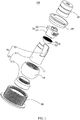
- FIG. 1 is an exploded structural diagram of a zoom LED lamp 100 according to the present invention.
- the zoom LED lamp 100 comprises a chip receiving cylinder 10, a chip fixing column 20 fixed in the chip receiving cylinder 10, a lens receiving cylinder 30 slidably arranged in the chip receiving cylinder 10, and a fixing cylinder 40 disposed on the lens receiving cylinder 30, a mounting barrel 50 for receiving the chip receiving cylinder 10, a block ring 60 disposed on the mounting cylinder 50, a lens 70 disposed in the lens receiving cylinder 30.
- the zoom LED lamp 100 further comprises other functional modules such as a mounting assembly, an electrical plug-in assembly, a light-emitting module disposed on the chip mounting post 20, and the like.
- the light-emitting module comprises a circuit Board, and at least one LED chip disposed on the circuit board.
- all of the above functional modules should be prior art and be well-known to those skilled in the art.
- the chip receiving cylinder 10 comprises a cylinder body 11, a radial positioning ring 12 disposed on the inner side wall of the cylinder body 11, a receiving groove 13 disposed on the radial positioning ring 12, and an elastic sealing ring 14 received in the receiving groove 13.
- the radial positioning ring 12 is set along the axial direction of the chip receiving cylinder10, that is, the axial height of the radial positioning ring 12 is smaller than the axial length of the chip receiving cylinder 10, and the axial height of the radial positioning ring 12 is half of the axial length of the cylinder body11.
- the radial positioning ring 12 can make sure that the lens receiving cylinder 30 can slide only in the axial direction of the cylinder body 11 while a gap between the lens receiving cylinder 30 and the cylinder body 11 can be formed.
- the gap can reduce the frictional area between the chip receiving cylinder 10 and the lens receiving cylinder 30, so that abrasion can be reduced.
- the receiving groove 13 is formed in an inner wall of the radial positioning ring 12 for receiving the elastic sealing ring 14.
- the receiving groove 13 should have the same size as the elastic sealing ring 14 so as to fix the position of the elastic sealing ring 14.
- the elastic sealing ring 14 may be made of an elastic material such as silicone rubber.
- the maximum diameter of the cross-section of the elastic sealing ring 14 should be greater than the maximum diameter of the cross-section of the receiving groove 13 so that the elastic sealing ring 14 abuts against the lens receiving cylinder 30 and the relative position of the lens receiving cylinder 30 to the chip receiving cylinder 10 is fixed when no external force is applied thereto.
- the lens receiving cylinder 30 is pushed and pulled by an external force in the axial direction of the cylinder body 11, the lens receiving cylinder 30 can move back and forth or up and down along the axial direction of the cylinder body 11.
- the outer side wall of the chip receiving cylinder 10 may be a spherical shape so as to be rotatable in the mounting barrel 50 and then can be irradiated with different directions.
- the specific structure of the chip receiving cylinder 10 will be described in detail below.
- the chip fixing column 20 is fixed in the chip receiving cylinder 10 and comprises a column body 21 spaced apart from the inner side wall of the chip receiving cylinder 10 and at least two ears 22 extending from the column body 21.
- the column body 21 is configured to dispose the light-emitting module. Specifically, the light-emitting module is disposed on the cross-section of the column body 21.
- the column body 21 is spaced apart from the inner sidewall of the cylinder body 11 so as to pass through the lens receiving cylinder 30 so that the lens receiving cylinder 30 can move back and forth or up and down in the gap between the column body 21 and the inner sidewall of the cylinder body 11 to achieve the purpose of zooming.
- the two ears 22 extend from the column body 21 and are fixed in the chip receiving cylinder10. Specifically, the two ears 22 are screwed on the inner sidewall of the cylinder body 11. The two ears 22 are disposed at a distance from the radial positioning ring 12 to avoid interference with the sliding of the lens receiving cylinder30.
- the lens receiving cylinder 30 comprises a lens cylinder 31 and two openings 32 opened on the lens cylinder 31 and respectively inserted into the two ears.
- the lens cylinder 31 comprises an inner sleeve 311 and a lampshade 312 disposed on the inner sleeve 311.
- the two openings 32 are disposed on the inner sleeve 311 and disposed on the other side of the inner sleeve 311 with respect to the lampshade 312 in the axial direction.
- the inner sleeve 311 is disposed between the cylinder body 11 of the chip receiving cylinder 10 and the column body 21 of the chip fixing column 20 and is positioned by the radial positioning ring 12 and the elastic sealing ring 14.
- the inner sleeve 311 may be integrally formed with the lampshade 312, or may be screwed together. In this embodiment, the inner sleeve 311 and the shade 312 are screwed together. When the inner sleeve 311 and the lampshade 312 are screwed together, the lens 70 can be sandwiched between the inner sleeve 311 and the lampshade 312, so that the assembly of the lens 70 can be completed. When the inner sleeve 311 and the lampshade 312 are integrally formed, an additional assembling mechanism needs to be designed to assemble the lens 70.
- the inner sleeve 311 is provided with a step
- the lens receiving cylinder further comprises an inner ring latching the lens 70 so that the lens 70 is sandwiched between the step and the inner ring.
- the structure is relatively simple and should be conceivable to those skilled in the art.
- the fixing cylinder 40 is disposed on an opening side of the lens cylinder 31 of the lens receiving cylinder 30 so that the two ears 22 of the chip fixing column 20 can be sandwiched between the lens cylinder 31 and the fixing cylinder 40 thus the distance by which the lens receiving cylinder 30 slides in the axial direction thereof can be defined.
- the fixing cylinder 40 and the lens receiving cylinder 30 may be fixed by any conventional technology, such as riveting and welding.
- the fixed barrel 40 is screwed into the inner sleeve 311 of the lens cylinder 30.
- the mounting barrel 50 is used to receive the chip receiving cylinder 10, and is also used to mount the zoom LED lamp 100 on a cabinet such as a showcase. How to install the cabinet 50 onto the cabinet through at least the mounting cylinder 50 should be a technology known to those skilled in the art and will not be described in detail here.
- one end of the mounting barrel has a limiting ring 51.
- the diameter of the stop ring 51 is smaller than the maximum outer diameter of the chip receiving cylinder 10.
- An elastic ring 52 is further disposed on an inner sidewall of the mounting barrel 50. The chip receiving cylinder 10 is clamped between the elastic ring 52 and an opening of one end of the mounting barrel 50.
- the inner wall of the mounting barrel 50 should also be spherical.
- the diameter of the elastic ring 52 is smaller than the maximum outer diameter of the chip receiving cylinder 10 so as to prevent the chip receiving cylinder 10 from slipping out of the elastic ring 52. It is conceivable that in order to be able to operate the lens cylinder 30, the length of the lens cylinder 30 and the fixing cylinder 40 in the axial direction thereof should be greater than the length of the mounting barrel 50.
- the block ring 60 is disposed on the mounting cylinder 50.
- the chip receiving cylinder 10 is sandwiched between the limiting ring 51 and the block ring 60.
- the function of the block ring 60 is to ensure that the chip receiving cylinder 10 can't slide out of the mounting cylinder 50.
- the lens 70 comprises a mounting portion 71 and a light distribution portion 72 connected to the mounting portion 71.
- the mounting portion 71 is sandwiched between the inner sleeve 311 and the shade 312 to fix the lens 70.
- the configuration of the light distributing portion 72 should be designed according to actual needs.
- the light distributing portion 72 is a convex lens for collecting light. It is well known that each lens comprises an optical axis. In the present embodiment, the lens cylinder 30 and the fixed barrel 40 together with the lens 70 move along the optical axis of the lens 70.
- the zoom LED lamp provided by the present invention can not only fix the lens receiving cylinder 30 by virtue of the chip receiving cylinder 10and the radial positioning ring 12 and the elastic sealing ring 14 provided on the chip receiving cylinder in the radial direction, and at the same time, the elastic sealing ring 14 can fix the position of the lens cylinder in the axial direction of the chip receiving cylinder 30 when no external force is applied.
- the chip fixing column 20 has the two ears 22, the sliding movement of the lens receiving cylinder 10 in the axial direction of the chip holding barrel can be limited, so that the irradiation range of the zoom LED lamp can be regulated.
Landscapes
- Engineering & Computer Science (AREA)
- General Engineering & Computer Science (AREA)
- Physics & Mathematics (AREA)
- Microelectronics & Electronic Packaging (AREA)
- Optics & Photonics (AREA)
- Led Device Packages (AREA)
- Fastening Of Light Sources Or Lamp Holders (AREA)
Applications Claiming Priority (1)
| Application Number | Priority Date | Filing Date | Title |
|---|---|---|---|
| CN201710897312.0A CN107514549A (zh) | 2017-09-28 | 2017-09-28 | 一种变焦led灯 |
Publications (1)
| Publication Number | Publication Date |
|---|---|
| EP3462083A1 true EP3462083A1 (fr) | 2019-04-03 |
Family
ID=60725706
Family Applications (1)
| Application Number | Title | Priority Date | Filing Date |
|---|---|---|---|
| EP18176339.2A Withdrawn EP3462083A1 (fr) | 2017-09-28 | 2018-06-06 | Lampe à del à zoom |
Country Status (3)
| Country | Link |
|---|---|
| US (1) | US10436420B2 (fr) |
| EP (1) | EP3462083A1 (fr) |
| CN (1) | CN107514549A (fr) |
Families Citing this family (7)
| Publication number | Priority date | Publication date | Assignee | Title |
|---|---|---|---|---|
| CN208124135U (zh) * | 2018-05-22 | 2018-11-20 | 苏州欧普照明有限公司 | 射灯 |
| GB2573024B (en) * | 2018-06-25 | 2020-12-30 | Ecoled Ltd | Modular luminaire support |
| CN208475253U (zh) * | 2018-07-27 | 2019-02-05 | 苏州欧普照明有限公司 | 一种变焦结构、灯头和照明装置 |
| CN109855051A (zh) * | 2018-12-27 | 2019-06-07 | 赛尔富电子有限公司 | 一种可螺旋式调节变焦灯具 |
| WO2020216206A1 (fr) * | 2019-04-25 | 2020-10-29 | 苏州欧普照明有限公司 | Ensemble de distribution de lumière et dispositif d'éclairage |
| CN113008211A (zh) * | 2019-12-19 | 2021-06-22 | 中国科学院沈阳自动化研究所 | 一种用于水下的紧凑型激光标尺 |
| CN114068789B (zh) * | 2021-11-15 | 2023-07-21 | 江苏欧密格光电科技股份有限公司 | 一种小角度可变焦的光源的制造方法 |
Citations (5)
| Publication number | Priority date | Publication date | Assignee | Title |
|---|---|---|---|---|
| CN201513729U (zh) * | 2009-08-19 | 2010-06-23 | 温州市瓯海潘桥乐邦电子厂 | 可变焦电筒 |
| KR20100132633A (ko) * | 2009-06-10 | 2010-12-20 | 주식회사 시공테크 | 줌 및 각도조절 기능을 구비한 led 조명장치 |
| WO2011031029A2 (fr) * | 2009-09-09 | 2011-03-17 | (주)이환 | Appareil d'éclairage pour une vitrine à propriétés culturelles |
| CN203615130U (zh) * | 2013-11-18 | 2014-05-28 | 广东凯西欧照明有限公司 | 一种可变焦led灯组件 |
| CN203823569U (zh) * | 2014-04-04 | 2014-09-10 | 马维理 | 调焦照明灯具 |
Family Cites Families (11)
| Publication number | Priority date | Publication date | Assignee | Title |
|---|---|---|---|---|
| ES1068734Y (es) * | 2008-09-08 | 2009-03-01 | Barbolight S L | Dispositivo de enfoque del haz luminoso en elementos de iluminacion con camara humeda. |
| CN102235577B (zh) * | 2010-04-30 | 2013-08-21 | 崔建青 | 一种变焦手电筒 |
| US9416937B2 (en) * | 2012-06-06 | 2016-08-16 | Coast Cutlery Co. | Thin profile lens for flashlight |
| CN203147299U (zh) * | 2013-02-26 | 2013-08-21 | 陈贤青 | 一种双透镜变焦手电筒 |
| CN203784759U (zh) * | 2014-03-29 | 2014-08-20 | 郑州枫华实业有限公司 | 博物馆用调焦led灯具 |
| CN103883943A (zh) * | 2014-04-04 | 2014-06-25 | 马维理 | 调焦照明灯具 |
| DE102015214949B4 (de) * | 2015-08-05 | 2021-12-23 | H4X E.U. | Innenraumleuchte zur Regal- oder Vitrinenbeleuchtung und Verfahren zur Herstellung |
| CN205606473U (zh) * | 2016-03-08 | 2016-09-28 | 深圳恩可光电科技有限公司 | 一种led灯具推拉套筒调焦装置 |
| CN106195927A (zh) * | 2016-08-31 | 2016-12-07 | 成都恒坤光电科技有限公司 | 一种变焦投影光学系统及变焦投影灯 |
| CN106969330A (zh) * | 2017-04-11 | 2017-07-21 | 欧普照明股份有限公司 | 一种射灯 |
| CN207213674U (zh) * | 2017-09-28 | 2018-04-10 | 赛尔富电子有限公司 | 一种变焦led灯 |
-
2017
- 2017-09-28 CN CN201710897312.0A patent/CN107514549A/zh active Pending
-
2018
- 2018-05-04 US US15/971,728 patent/US10436420B2/en active Active
- 2018-06-06 EP EP18176339.2A patent/EP3462083A1/fr not_active Withdrawn
Patent Citations (5)
| Publication number | Priority date | Publication date | Assignee | Title |
|---|---|---|---|---|
| KR20100132633A (ko) * | 2009-06-10 | 2010-12-20 | 주식회사 시공테크 | 줌 및 각도조절 기능을 구비한 led 조명장치 |
| CN201513729U (zh) * | 2009-08-19 | 2010-06-23 | 温州市瓯海潘桥乐邦电子厂 | 可变焦电筒 |
| WO2011031029A2 (fr) * | 2009-09-09 | 2011-03-17 | (주)이환 | Appareil d'éclairage pour une vitrine à propriétés culturelles |
| CN203615130U (zh) * | 2013-11-18 | 2014-05-28 | 广东凯西欧照明有限公司 | 一种可变焦led灯组件 |
| CN203823569U (zh) * | 2014-04-04 | 2014-09-10 | 马维理 | 调焦照明灯具 |
Also Published As
| Publication number | Publication date |
|---|---|
| US20190093861A1 (en) | 2019-03-28 |
| CN107514549A (zh) | 2017-12-26 |
| US10436420B2 (en) | 2019-10-08 |
Similar Documents
| Publication | Publication Date | Title |
|---|---|---|
| US10436420B2 (en) | Zoom LED lamp with slidable lens | |
| US10359154B2 (en) | Assembly including a diffuser for a lighting device | |
| EP3323318A1 (fr) | Lampe à filament à del | |
| US20160377258A1 (en) | Spread light lens and led strip lights having same | |
| US8240886B2 (en) | Illumination device with anti-glare function | |
| CN111649263B (zh) | 一种近距离照明的光学模组及灯具 | |
| US9964292B2 (en) | Angle adjustment mechanism for LED bar lighting | |
| US10598340B2 (en) | LED lamp light distribution system and illumination system | |
| US20120140467A1 (en) | Led lamp | |
| EP2869106A1 (fr) | Lentille et module de DEL ayant celui-ci | |
| CN103836405B (zh) | 灯具 | |
| US9127828B2 (en) | Lamp with uniform illumination pattern | |
| US10072806B1 (en) | Luminaire downlight | |
| JP2017050188A (ja) | 照明器具 | |
| CN101749638B (zh) | 室内灯具 | |
| CN103591519A (zh) | 止动环限位的双圆旋转调焦天花灯 | |
| CN212056914U (zh) | 一种出光角度可调的射灯 | |
| CN210153585U (zh) | 一种方便调节照明区域的灯具 | |
| KR101782069B1 (ko) | Led 가로등 | |
| US10151467B2 (en) | Interconnection mechanism for LED bar lighting | |
| US10948138B2 (en) | Filter lens, LED lamp with filter lens and illumination system | |
| CN204986872U (zh) | 多个反光片组成的反射光线模组结构 | |
| CN211118936U (zh) | 灯体单元和照明灯具 | |
| CN207213674U (zh) | 一种变焦led灯 | |
| CN222864772U (zh) | 可调式出光口径的照明灯具及照明设备 |
Legal Events
| Date | Code | Title | Description |
|---|---|---|---|
| PUAI | Public reference made under article 153(3) epc to a published international application that has entered the european phase |
Free format text: ORIGINAL CODE: 0009012 |
|
| STAA | Information on the status of an ep patent application or granted ep patent |
Free format text: STATUS: THE APPLICATION HAS BEEN PUBLISHED |
|
| AK | Designated contracting states |
Kind code of ref document: A1 Designated state(s): AL AT BE BG CH CY CZ DE DK EE ES FI FR GB GR HR HU IE IS IT LI LT LU LV MC MK MT NL NO PL PT RO RS SE SI SK SM TR |
|
| AX | Request for extension of the european patent |
Extension state: BA ME |
|
| STAA | Information on the status of an ep patent application or granted ep patent |
Free format text: STATUS: REQUEST FOR EXAMINATION WAS MADE |
|
| 17P | Request for examination filed |
Effective date: 20191003 |
|
| RBV | Designated contracting states (corrected) |
Designated state(s): AL AT BE BG CH CY CZ DE DK EE ES FI FR GB GR HR HU IE IS IT LI LT LU LV MC MK MT NL NO PL PT RO RS SE SI SK SM TR |
|
| RIC1 | Information provided on ipc code assigned before grant |
Ipc: F21V 14/06 20060101AFI20200121BHEP Ipc: F21Y 115/10 20160101ALN20200121BHEP Ipc: F21V 17/02 20060101ALI20200121BHEP Ipc: F21W 131/301 20060101ALN20200121BHEP Ipc: F21V 31/00 20060101ALN20200121BHEP Ipc: F21V 5/04 20060101ALN20200121BHEP Ipc: F21V 21/30 20060101ALN20200121BHEP |
|
| GRAP | Despatch of communication of intention to grant a patent |
Free format text: ORIGINAL CODE: EPIDOSNIGR1 |
|
| STAA | Information on the status of an ep patent application or granted ep patent |
Free format text: STATUS: GRANT OF PATENT IS INTENDED |
|
| INTG | Intention to grant announced |
Effective date: 20200304 |
|
| STAA | Information on the status of an ep patent application or granted ep patent |
Free format text: STATUS: THE APPLICATION IS DEEMED TO BE WITHDRAWN |
|
| 18D | Application deemed to be withdrawn |
Effective date: 20200715 |