EP3462191A1 - Schaltkreis zur detektion eines masseschlussfehlers, umwandlungskette, die einen solchen schaltkreis umfasst, und detektionsverfahren eines masseschlussfehlers - Google Patents
Schaltkreis zur detektion eines masseschlussfehlers, umwandlungskette, die einen solchen schaltkreis umfasst, und detektionsverfahren eines masseschlussfehlers Download PDFInfo
- Publication number
- EP3462191A1 EP3462191A1 EP18197437.9A EP18197437A EP3462191A1 EP 3462191 A1 EP3462191 A1 EP 3462191A1 EP 18197437 A EP18197437 A EP 18197437A EP 3462191 A1 EP3462191 A1 EP 3462191A1
- Authority
- EP
- European Patent Office
- Prior art keywords
- current
- bus
- link
- current sensor
- ground fault
- Prior art date
- Legal status (The legal status is an assumption and is not a legal conclusion. Google has not performed a legal analysis and makes no representation as to the accuracy of the status listed.)
- Withdrawn
Links
- 238000001514 detection method Methods 0.000 title claims abstract description 30
- 230000009466 transformation Effects 0.000 title claims description 5
- 238000005259 measurement Methods 0.000 claims description 13
- 238000000034 method Methods 0.000 claims description 10
- 230000007547 defect Effects 0.000 claims description 5
- 238000012545 processing Methods 0.000 description 9
- 238000012360 testing method Methods 0.000 description 5
- 230000007257 malfunction Effects 0.000 description 4
- 238000012423 maintenance Methods 0.000 description 2
- 208000019300 CLIPPERS Diseases 0.000 description 1
- 230000005355 Hall effect Effects 0.000 description 1
- 230000000712 assembly Effects 0.000 description 1
- 238000000429 assembly Methods 0.000 description 1
- 239000003990 capacitor Substances 0.000 description 1
- 208000021930 chronic lymphocytic inflammation with pontine perivascular enhancement responsive to steroids Diseases 0.000 description 1
- 230000000694 effects Effects 0.000 description 1
- 238000000105 evaporative light scattering detection Methods 0.000 description 1
Images

Classifications
-
- B—PERFORMING OPERATIONS; TRANSPORTING
- B60—VEHICLES IN GENERAL
- B60L—PROPULSION OF ELECTRICALLY-PROPELLED VEHICLES; SUPPLYING ELECTRIC POWER FOR AUXILIARY EQUIPMENT OF ELECTRICALLY-PROPELLED VEHICLES; ELECTRODYNAMIC BRAKE SYSTEMS FOR VEHICLES IN GENERAL; MAGNETIC SUSPENSION OR LEVITATION FOR VEHICLES; MONITORING OPERATING VARIABLES OF ELECTRICALLY-PROPELLED VEHICLES; ELECTRIC SAFETY DEVICES FOR ELECTRICALLY-PROPELLED VEHICLES
- B60L3/00—Electric devices on electrically-propelled vehicles for safety purposes; Monitoring operating variables, e.g. speed, deceleration or energy consumption
- B60L3/0023—Detecting, eliminating, remedying or compensating for drive train abnormalities, e.g. failures within the drive train
- B60L3/0038—Detecting, eliminating, remedying or compensating for drive train abnormalities, e.g. failures within the drive train relating to sensors
-
- B—PERFORMING OPERATIONS; TRANSPORTING
- B60—VEHICLES IN GENERAL
- B60L—PROPULSION OF ELECTRICALLY-PROPELLED VEHICLES; SUPPLYING ELECTRIC POWER FOR AUXILIARY EQUIPMENT OF ELECTRICALLY-PROPELLED VEHICLES; ELECTRODYNAMIC BRAKE SYSTEMS FOR VEHICLES IN GENERAL; MAGNETIC SUSPENSION OR LEVITATION FOR VEHICLES; MONITORING OPERATING VARIABLES OF ELECTRICALLY-PROPELLED VEHICLES; ELECTRIC SAFETY DEVICES FOR ELECTRICALLY-PROPELLED VEHICLES
- B60L3/00—Electric devices on electrically-propelled vehicles for safety purposes; Monitoring operating variables, e.g. speed, deceleration or energy consumption
- B60L3/0023—Detecting, eliminating, remedying or compensating for drive train abnormalities, e.g. failures within the drive train
- B60L3/0069—Detecting, eliminating, remedying or compensating for drive train abnormalities, e.g. failures within the drive train relating to the isolation, e.g. ground fault or leak current
-
- G—PHYSICS
- G01—MEASURING; TESTING
- G01R—MEASURING ELECTRIC VARIABLES; MEASURING MAGNETIC VARIABLES
- G01R31/00—Arrangements for testing electric properties; Arrangements for locating electric faults; Arrangements for electrical testing characterised by what is being tested not provided for elsewhere
- G01R31/50—Testing of electric apparatus, lines, cables or components for short-circuits, continuity, leakage current or incorrect line connections
- G01R31/52—Testing for short-circuits, leakage current or ground faults
-
- G—PHYSICS
- G01—MEASURING; TESTING
- G01R—MEASURING ELECTRIC VARIABLES; MEASURING MAGNETIC VARIABLES
- G01R35/00—Testing or calibrating of apparatus covered by the other groups of this subclass
-
- G—PHYSICS
- G01—MEASURING; TESTING
- G01R—MEASURING ELECTRIC VARIABLES; MEASURING MAGNETIC VARIABLES
- G01R31/00—Arrangements for testing electric properties; Arrangements for locating electric faults; Arrangements for electrical testing characterised by what is being tested not provided for elsewhere
- G01R31/40—Testing power supplies
Definitions
- the present invention relates to a ground fault detection circuit comprising a DC bus, a current sensor and a resistor block (s) comprising at least one resistor, wherein the DC bus comprises a first link to a supply polarity given non-zero and a second link connected to ground by a connection, said sensor sensing the current flowing on said connection, and a terminal of the resistance block being connected to said first link of the bus via an electronic switch, in wherein said detection circuit is adapted to detect a ground fault, as a function of the current sensed by the current sensor when the bus is powered by AC current converted to direct current.
- Such a circuit is for example mentioned in the document US 4,430,683 .
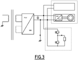
- the figure 3 of the present document also represents such a circuit in a chain comprising an AC voltage transformer, a DC AC converter, a set (dotted line) with switches and resistor and loads, a load including a voltage inverter and a motor, for example a traction motor.
- the detection circuit detects a ground fault in the event that a non-zero current is picked up by the current sensor present on the connection connecting the ground to one of the links of the bus. In the opposite case, it is considered that no earth fault occurs.
- Such a detection circuit does not allow to simply test the proper functioning of the sensor, since in the absence of a ground fault, no current flows through the sensor: it is then not possible to distinguish whether the absence of current measured is due to the absence of a mass fault or a malfunction of the sensor or its disconnection. To test the sensor, specific maintenance steps must be implemented, which increases the volume and time of maintenance operations.
- the invention proposes a ground fault detection circuit of the aforementioned type characterized in that a terminal of the resistance of the resistance block (s) is connected to a connection point to the mass located between the current sensor and the mass.
- the invention thus makes it possible to test the proper functioning of the detection circuit, automatically, while it is being used and without affecting its proper functioning.
- the present invention proposes a transformation chain comprising a detection circuit according to one of the preceding claims, an AC power supply, a DC AC converter disposed between said power supply and said detection circuit, and a voltage inverter coupled to a traction motor, the detection circuit bus being disposed between said traction inverter and said converter.
- the figure 1 represents a portion 1 of traction chain, for example implemented in a tram, and which implements an embodiment of the invention.
- This portion 1 of a trolley pull chain comprises a block 21 of energy transformation and a set of 7 charges.
- the set 7 of charges comprises one or more charges: in the case considered, 2 charges 71 and 72.
- the load 71 comprises a voltage inverter 73 and a traction motor 74, for example polyphase, in particular three-phase.
- the load 72 comprises for example an auxiliary converter.
- the transformation block 21 comprises a transformer 2, a converter 3, and a detection circuit 20.
- the detection circuit 20 comprises a DC bus 4, a ground connection 5, a current sensor 9 and a resistor (s) 10.
- the continuous bus 4 comprises two links: the link + HT 41 and the link -HT 42.
- the transformer 2 lowers the voltage level of the AC power supply, which is supplied to it as input, which originates, in this case, from the overhead supply line of the tramway.
- the transformer 2 comprises a primary circuit and one or more secondary circuits.
- the alternating current supply thus transformed by the transformer 2 is then supplied to the input of the converter 3, which converts the alternating current into direct current.
- the output voltage of the converter 3 is applied between the links + HT 41 and -HT 42 of the bus 4.
- a capacitor 6 is arranged between the links 41 and 42.
- the voltage between the links 41 and 42 is provided at the input of the respective charges 71, 72.
- the link -HT 42 is connected to an electrical ground 8 by the electrical connection 5.
- the electric current sensor 9 is disposed on the link 5, it is Hall effect type for example or other type (eg shunt, Néel effect etc.).
- the current sensor 9 thus measures the electric current flowing on the link 5.
- the resistance assembly (s) 10 is an electrical circuit comprising at least one resistor 15 and possibly other components depending on the cases considered.
- the resistor (s) 10 is a rheostat which comprises four insulated gate bipolar transistors, called IGBTs (of the "Insulated Gate Bipolar Transistor") 11, 12, 13, 14. Sa function is to dissipate the energy reinjected by braking the tramway.
- the IGBTs are cyclically controlled and thus behave cyclically in open or closed switches, and are connected to the bus 4.
- the collectors of the IGBTs 11 and 13 are connected to the link + HT 41 of the bus 4.
- the IGBTs 11 and 12 are arranged in series, the emitter of the IGBT 11 being connected to the collector of the IGBT 12.
- the IGBTs 13 and 14 are arranged in series, the transmitter of the IGBT 13 being connected to the collector of the IGBT 14. These two series are arranged in parallel assembly.
- a terminal of the resistor (s) assembly 10 connected to the IGBT collectors 11 and 13 is connected to the + HT 41 link.
- a terminal of the resistor (s) assembly 10 connected to the emitters of the IGBTs 12 and 14 is further connected to the link -HT 42.
- One terminal of the resistor 15 is connected to the emitter of the IGBT 11 and the other terminal of the resistor 15 is connected by an electrical connection 22 to the ground 8 directly, or, more generally, to a point arranged between the current sensor 9 and the ground 8, on the electrical connection 5.
- a current sensor 17 is disposed on the link 22.
- the current sensor 17 thus measures the electric current flowing on the link 22.
- the resistance assembly (s) 10 has one or more resistors.
- a resistor 16 is further arranged in parallel with the IGBT 14 and a current sensor 18 is disposed on the link connecting a terminal of the resistor and the emitter of the IGBT 14.
- the detection circuit 20 further comprises a processing block (not shown) comprising calculation means.
- This processing block is adapted to implement, on a regular basis, the set of steps represented in FIG. figure 2 to detect a mass problem and a malfunction of the sensor 9, as soon as the rheostat is controlled (ie at least one of the switches is controlled in closing according to a given control profile).
- the processing block regularly collects the measurements of the current flowing on the link 5 made by the current sensor 9 and the measurements of current flowing on the link 22 made by the current sensor 17. Then, for each instant In a subsequent step, the processing block calculates the difference between a current measurement performed by the current sensor 9 and a current measurement performed by the current sensor 17 corresponding to the same measurement instant.
- the processing block compares to a first predetermined threshold the absolute value of the difference calculated per measurement instant considered. And the processing block determines the presence or absence of a mass defect depending on the result of this comparison. In the present case, a ground fault is detected if the difference value in absolute value is greater than said threshold.
- the threshold is a value equal to 50 amperes (A), or more generally selected in the range [10 A, 1000 A].
- the processing block is adapted for in step 102, to detect that the current sensor 9 has a malfunction, which corresponds to a zero current measured by the sensor 9 when the IGBTs of the resistance assembly 10 are controlled by the presence of noise: thus, a fault of the sensor 9 is detected if the absolute value of the current in the sensor 9 is less than a second predetermined threshold, less than the first threshold, for example a value equal to 20 A, or more generally selected in the range [10 A, 200 A].
- the present invention thus proposes a detection circuit making it possible both to detect the mass problems, while also permitting during the nominal operation of the circuit, to test the correct operation of the sensor of the detector.
- the resistance assembly (s) 10 considered above is a rheostat of a given structure, but the invention can of course be implemented with resistance assemblies (s) of different and varied structures.
- the resistance unit (s) 10 generally comprises at least one terminal connected to the link + HT 41 of the bus 4. It is adapted to regulate the power present on the bus, for example by means of a control function of the voltage present on the overhead line. It is example of type chopper, clipper, rheostat. For example, it is adapted to absorb the overvoltages at the terminals of the continuous bus 4, to absorb the braking power generated when braking the tram etc.
- the invention can also be implemented without any current sensor being disposed on the link connecting a resistance of the resistance assembly (s) 10 to a point located, on the link 5, between the 8 and the current sensor 9.
- the processing block regularly collects current measurements flowing on the link 5 made by the current sensor 9. Again, it compares the absolute value of each current measurement. (or a value representative of said current measurements, for example an average of a number of the last measurements etc.) at a third predetermined threshold. And it determines the presence or absence of a mass defect depending on the result of this comparison when no switch of the resistance assembly 10 is controlled at closing.
- a ground fault is detected if the current value in absolute value is greater than said third threshold.
- the third threshold at which the measured current is compared is a value equal to 50A, or more generally selected in the range [10A, 1000A].
- the processing unit is adapted to detect that the current sensor 9 has a malfunction, which corresponds to a current measured by the sensor 9 when the IGBTs of the resistance assembly 10 are controlled by means of the presence of noise. : thus, a fault of the sensor 9 is detected if the absolute value of the current in the sensor 9 is lower than a fourth predetermined threshold, lower than the third threshold, for example of value equal to 20 A, or more generally chosen in the range [ 10A, 200A].
Landscapes
- Engineering & Computer Science (AREA)
- Life Sciences & Earth Sciences (AREA)
- Sustainable Development (AREA)
- Sustainable Energy (AREA)
- Power Engineering (AREA)
- Transportation (AREA)
- Mechanical Engineering (AREA)
- Physics & Mathematics (AREA)
- General Physics & Mathematics (AREA)
- Testing Of Short-Circuits, Discontinuities, Leakage, Or Incorrect Line Connections (AREA)
- Inverter Devices (AREA)
Applications Claiming Priority (1)
| Application Number | Priority Date | Filing Date | Title |
|---|---|---|---|
| FR1759058A FR3071928B1 (fr) | 2017-09-29 | 2017-09-29 | Circuit de detection de defaut de masse, chaine de transformation comprenant un tel circuit, procede de detection de defaut de masse. |
Publications (1)
| Publication Number | Publication Date |
|---|---|
| EP3462191A1 true EP3462191A1 (de) | 2019-04-03 |
Family
ID=61027848
Family Applications (1)
| Application Number | Title | Priority Date | Filing Date |
|---|---|---|---|
| EP18197437.9A Withdrawn EP3462191A1 (de) | 2017-09-29 | 2018-09-28 | Schaltkreis zur detektion eines masseschlussfehlers, umwandlungskette, die einen solchen schaltkreis umfasst, und detektionsverfahren eines masseschlussfehlers |
Country Status (2)
| Country | Link |
|---|---|
| EP (1) | EP3462191A1 (de) |
| FR (1) | FR3071928B1 (de) |
Citations (5)
| Publication number | Priority date | Publication date | Assignee | Title |
|---|---|---|---|---|
| US4430683A (en) * | 1981-02-27 | 1984-02-07 | Hitachi, Ltd. | Ground fault detecting device for use with a DC circuit |
| EP1818207A2 (de) * | 2006-02-10 | 2007-08-15 | Kabushiki Kaisha Toshiba | Steuervorrichtung für elektrisches Rollmaterial |
| EP2765664A1 (de) * | 2011-10-03 | 2014-08-13 | Panasonic Corporation | Energieaufladevorrichtung für ein elektrofahrzeug |
| US20150256116A1 (en) * | 2014-03-05 | 2015-09-10 | Fanuc Corporation | Motor drive device having insulation resistance detecting function and method of detecting insulation resistance of motors |
| DE102015106069A1 (de) * | 2014-04-22 | 2015-10-22 | Hitachi Automotive Systems, Ltd. | Elektrische Motoransteuerungsvorrichtung |
-
2017
- 2017-09-29 FR FR1759058A patent/FR3071928B1/fr active Active
-
2018
- 2018-09-28 EP EP18197437.9A patent/EP3462191A1/de not_active Withdrawn
Patent Citations (5)
| Publication number | Priority date | Publication date | Assignee | Title |
|---|---|---|---|---|
| US4430683A (en) * | 1981-02-27 | 1984-02-07 | Hitachi, Ltd. | Ground fault detecting device for use with a DC circuit |
| EP1818207A2 (de) * | 2006-02-10 | 2007-08-15 | Kabushiki Kaisha Toshiba | Steuervorrichtung für elektrisches Rollmaterial |
| EP2765664A1 (de) * | 2011-10-03 | 2014-08-13 | Panasonic Corporation | Energieaufladevorrichtung für ein elektrofahrzeug |
| US20150256116A1 (en) * | 2014-03-05 | 2015-09-10 | Fanuc Corporation | Motor drive device having insulation resistance detecting function and method of detecting insulation resistance of motors |
| DE102015106069A1 (de) * | 2014-04-22 | 2015-10-22 | Hitachi Automotive Systems, Ltd. | Elektrische Motoransteuerungsvorrichtung |
Also Published As
| Publication number | Publication date |
|---|---|
| FR3071928A1 (fr) | 2019-04-05 |
| FR3071928B1 (fr) | 2019-11-22 |
Similar Documents
| Publication | Publication Date | Title |
|---|---|---|
| EP3149853B1 (de) | Feldeffekttransistor und zugehörige fehlerdetektionsvorrichtung | |
| EP2634884B1 (de) | Einspeisungskette einer synchronen elektrischen Maschine, elektrisches Antriebssystem, das eine solche Kette umfasst, und Steuerverfahren einer solchen Kette | |
| US7639021B2 (en) | Circuit and method for detecting a dielectric breakdown fault | |
| EP2859636B1 (de) | Gegen externe kurzschlüsse geschützte akkumulatorenbatterie | |
| EP3590172B1 (de) | Verfahren zur steuerung einer bordeigenen, an ein einphasiges oder dreiphasiges stromversorgungsnetz angeschlossenen fahrzeugbatterieladevorrichtung | |
| FR3000322A1 (fr) | Dispositif de protection contre une surintensite electrique d'au moins une branche electronique de commutation, systeme de conversion comportant un tel dispositif de protection, et procede de pilotage associe | |
| EP3706151A1 (de) | Leistungsschalter mit vakuumtrennschalter, der ein steuersystem umfasst, und schienenfahrzeug, das einen solchen leistungsschalter umfasst | |
| EP2818879B1 (de) | Vorrichtung zum Schätzen der Impedanz einer elektrischen Erdverbindung, entsprechendes Schätzverfahren und entsprechendes Stromversorgungssystem | |
| FR3010255A1 (fr) | Procede de detection de panne d'un alternateur triphase, dispositif de detection de panne et programme d'ordinateur associe | |
| FR3071928B1 (fr) | Circuit de detection de defaut de masse, chaine de transformation comprenant un tel circuit, procede de detection de defaut de masse. | |
| CA2563273C (en) | Electric car control apparatus | |
| WO2016046465A1 (fr) | Dispositif et procédé de détermination d'une consigne corrigée du courant neutre d'un chargeur sans isolation galvanique de batterie de véhicule automobile électrique ou hybride | |
| FR3079305A1 (fr) | Procede de determination d'au moins deux resistances equivalentes d'isolement d'un systeme electrique | |
| FR3050405A1 (fr) | Procede de commande d'un chargeur embarque dans un vehicule electrique ou hybride a detection de charge en grappe | |
| CN102549911B (zh) | 车用发电电压控制装置 | |
| US11588322B2 (en) | Fault detection for a solid state power converter | |
| EP2737602A1 (de) | System zur überwachung eines gleichrichters zum laden einer batterie eines elektrokraftfahrzeugs | |
| US12153100B1 (en) | Emergency starting power supply with contact impedance detection | |
| EP4264764B1 (de) | Spannungswandler und kraftfahrzeug mit einem solchen spannungswandler | |
| EP3694091A1 (de) | Verfahren und system zum schutz eines stromversorgungsschaltkreises | |
| EP4392798B1 (de) | Verfahren zur überprüfung einer vorrichtung zur prüfung einer hilfsbatterie | |
| FR3049786A1 (fr) | Convertisseur d'energie electrique, chaine de traction comportant un tel convertisseur et vehicule electrique de transport associe | |
| EP3877774B1 (de) | Vorrichtung zur unterdrückung der stromabgabe aus einer vorrichtung mit schaltelementen für überwachte leckage | |
| FR2970822A1 (fr) | Dispositif de controle du rechargement d'une batterie electrique d'un systeme, par estimation d'impedance et/ou d'effet non lineaire parasite(s) en amont d'un chargeur | |
| FR3018609A1 (fr) | Procede et systeme de commande d'une machine electrique avec diagnostic de l'onduleur d'alimentation. |
Legal Events
| Date | Code | Title | Description |
|---|---|---|---|
| PUAI | Public reference made under article 153(3) epc to a published international application that has entered the european phase |
Free format text: ORIGINAL CODE: 0009012 |
|
| STAA | Information on the status of an ep patent application or granted ep patent |
Free format text: STATUS: THE APPLICATION HAS BEEN PUBLISHED |
|
| AK | Designated contracting states |
Kind code of ref document: A1 Designated state(s): AL AT BE BG CH CY CZ DE DK EE ES FI FR GB GR HR HU IE IS IT LI LT LU LV MC MK MT NL NO PL PT RO RS SE SI SK SM TR |
|
| AX | Request for extension of the european patent |
Extension state: BA ME |
|
| STAA | Information on the status of an ep patent application or granted ep patent |
Free format text: STATUS: REQUEST FOR EXAMINATION WAS MADE |
|
| 17P | Request for examination filed |
Effective date: 20190412 |
|
| RBV | Designated contracting states (corrected) |
Designated state(s): AL AT BE BG CH CY CZ DE DK EE ES FI FR GB GR HR HU IE IS IT LI LT LU LV MC MK MT NL NO PL PT RO RS SE SI SK SM TR |
|
| GRAP | Despatch of communication of intention to grant a patent |
Free format text: ORIGINAL CODE: EPIDOSNIGR1 |
|
| STAA | Information on the status of an ep patent application or granted ep patent |
Free format text: STATUS: GRANT OF PATENT IS INTENDED |
|
| RIC1 | Information provided on ipc code assigned before grant |
Ipc: G01R 31/40 20140101ALN20220201BHEP Ipc: G01R 35/00 20060101ALI20220201BHEP Ipc: B60L 3/00 20190101ALI20220201BHEP Ipc: G01R 31/52 20200101AFI20220201BHEP |
|
| INTG | Intention to grant announced |
Effective date: 20220225 |
|
| STAA | Information on the status of an ep patent application or granted ep patent |
Free format text: STATUS: THE APPLICATION IS DEEMED TO BE WITHDRAWN |
|
| 18D | Application deemed to be withdrawn |
Effective date: 20220708 |