EP3462192A1 - Procédé d'installation d'un système d'entraînement et système d'entraînement - Google Patents
Procédé d'installation d'un système d'entraînement et système d'entraînement Download PDFInfo
- Publication number
- EP3462192A1 EP3462192A1 EP17194070.3A EP17194070A EP3462192A1 EP 3462192 A1 EP3462192 A1 EP 3462192A1 EP 17194070 A EP17194070 A EP 17194070A EP 3462192 A1 EP3462192 A1 EP 3462192A1
- Authority
- EP
- European Patent Office
- Prior art keywords
- communication module
- information
- drive system
- consumer
- load
- Prior art date
- Legal status (The legal status is an assumption and is not a legal conclusion. Google has not performed a legal analysis and makes no representation as to the accuracy of the status listed.)
- Withdrawn
Links
- 238000000034 method Methods 0.000 title claims abstract description 16
- 238000004891 communication Methods 0.000 claims description 61
- 238000004146 energy storage Methods 0.000 description 2
- 230000005540 biological transmission Effects 0.000 description 1
- 230000001419 dependent effect Effects 0.000 description 1
- 238000001514 detection method Methods 0.000 description 1
- 238000011161 development Methods 0.000 description 1
- 230000018109 developmental process Effects 0.000 description 1
- 238000009434 installation Methods 0.000 description 1
- 238000005259 measurement Methods 0.000 description 1
- 230000010363 phase shift Effects 0.000 description 1
Images

Classifications
-
- G—PHYSICS
- G01—MEASURING; TESTING
- G01R—MEASURING ELECTRIC VARIABLES; MEASURING MAGNETIC VARIABLES
- G01R31/00—Arrangements for testing electric properties; Arrangements for locating electric faults; Arrangements for electrical testing characterised by what is being tested not provided for elsewhere
- G01R31/50—Testing of electric apparatus, lines, cables or components for short-circuits, continuity, leakage current or incorrect line connections
- G01R31/66—Testing of connections, e.g. of plugs or non-disconnectable joints
- G01R31/67—Testing the correctness of wire connections in electric apparatus or circuits
-
- G—PHYSICS
- G01—MEASURING; TESTING
- G01R—MEASURING ELECTRIC VARIABLES; MEASURING MAGNETIC VARIABLES
- G01R31/00—Arrangements for testing electric properties; Arrangements for locating electric faults; Arrangements for electrical testing characterised by what is being tested not provided for elsewhere
- G01R31/40—Testing power supplies
- G01R31/42—AC power supplies
Definitions
- the invention relates to a method for installing a drive system and a drive system.
- the power line for a multi-phase alternating voltage usually includes a plurality of individual lines for connection to the consumer.
- the individual lines are also referred to as power phases.
- the object is achieved by a method according to claim 1.
- the process of connecting the load to the power line is considered.
- the individual phases of the current are present as loose connection cables, which are each connected to the respectively provided connection of the consumer.
- a check is made with the methods described here as to whether the connection is made correctly.
- the analysis signal can each be a signal in which the respective current phase is coded.
- a comparison of the respective analysis signal with the respectively present pin assignment is compared.
- phase (s) of current is not connected according to the intended terminal assignment.
- this can also be displayed.
- the display can be exemplified by a light emitting diode, which lights up in accordance with the pin assignment with the intended pin assignment green and otherwise outputs a red signal.
- the display can also be carried out with the aid of a display module.
- the power source has a second communication module, wherein the consumer is associated with an identifier, with the aid of the first communication module of the information the identifier is added, with the aid of the first communication module and the second communication module, the information to the power source is transmitted.
- the settings of the current source in particular an assignment of the current phases, are changed on the basis of the information.
- the analysis signal does not affect the state of the consumer or only insignificantly.
- the information is alternatively or additionally one decentralized computing unit, in particular a cloud.
- the first communication module is supplied by the power source with electrical energy, in particular with the analysis signal.
- the information is transmitted via a wireless data connection.
- the transmission takes place in particular by means of a data connection according to a GSM standard, to a G3, to a G4, to a G5 standard or via a WLAN connection.
- the drive system has a power supply, in particular a frequency converter, and a consumer, in particular a motor, wherein the consumer is connected by a power line to the power source, wherein the consumer is associated with a first communication module, wherein the power supply is provided for providing an analysis signal wherein the power line comprises a plurality of power phases, wherein the first communication module is provided for checking a terminal assignment to the consumer with the aid of the analysis signal, whether the terminal assignment of the respective current phase corresponds to the intended terminal occupation, wherein the first communication module is provided for providing information based on the check, wherein a display module is provided for displaying the information.
- a power supply in particular a frequency converter
- a consumer in particular a motor
- the consumer is connected by a power line to the power source
- the consumer is associated with a first communication module
- the power supply is provided for providing an analysis signal
- the power line comprises a plurality of power phases
- the first communication module is provided for checking a terminal assignment to the consumer with the aid of the analysis signal,
- the display module is designed as a mobile display module, in particular as a smartphone.
- the consumer and / or the first communication module to an identifier, wherein the identifier is provided for provision of the information.
- the identifier with the display module can be detected directly.
- a voltage divider is provided for the power supply of the first communication module, wherein the voltage divider is connected to the power line.
- the power supply to a second communication module, wherein the second communication module is adapted to receive the information.
- the first communication module and the second communication module for transmitting information via the display module are formed.
- the second communication module has an energy store, wherein the power line, in particular via a voltage converter, supplies the energy store with power.
- FIG. 1 shows an exemplary drive system.
- the drive system shown here has a frequency converter as the current source 1.
- the power source 1 is connected to the load 5 via a power line 3.
- the power line 3 serves to transmit the current or the voltage for the consumer.
- the consumer 5 is shown here as a motor.
- the consumer 5 is assigned an identifier 7.
- the identifier 7 is used to identify the consumer 5.
- the identifier 7 has technical data of the consumer 5 on.
- the consumer 5 is assigned a first communication module 5a.
- the first communication module 5a may be implemented as a microcomputer.
- the first communication module 5a serves to transmit information 9 to a second communication module 1a.
- the information 9 is preferably transmitted wirelessly, for example by WLAN.
- the second communication module 1a is assigned to the power supply 1.
- the communication modules are used to transmit the identifier 7 of the consumer 5 to the power source 1.
- settings of the power source 1 such as respective current phase u, v, w, set.
- An adjustment of the respective current phase u, v, w may be the voltage, the maximum current or a phase shift of a multiphase AC voltage provided by the current source 1 to the load 5.
- the information 9 of the connection is provided to the second communication module 1a with the aid of the first communication module 5a.
- the information 9 includes whether the respective current phase u, v, w is connected to the consumer according to the defined terminal assignment.
- the check on which the terminal assignment of the current phases u, v, w is correct is advantageously carried out by the measurement the phase relationship of individual current phases u, v, w to each other. If the respective current phase u, v, q is not connected to the load according to the intended terminal assignment, the current source can change the respective current phase u, v, w and thus correct a wrongly connected power line 3.
- FIG. 2 shows another exemplary drive system.
- the drive system shown has a power source 1 and a consumer 5.
- the consumer is connected via a power line 3 to the power source 1.
- the power line 3 comprises three phases u, v, w.
- the first phase u is the first phase of a 3-phase alternating current.
- the consumer 5 is assigned a first communication module 5a.
- the first communication module 5a is connected via a voltage divider 13 to the power line 3.
- the first communication module 5a provides the information 9 to a display module 11.
- the display module 11 is preferably designed as a mobile human machine interface (mobile HMI).
- the display module 11 serves to display the information 9.
- the information is in particular a connection information.
- the first communication module 5a provides the information 9 with respect to the connection to a second communication module 1a.
- the second communication module 1a is assigned to the current source 1.
- a signal is transmitted to the power source, preferably with the aid of the communication modules 1a, 5a.
- the power source provides through the power line 3 an analysis stream. Based on the analysis stream, the communication module determines whether the connection of the consumer 5 has been made to the power line 3 properly. The result of Detection is indicated by the display module 11 and provided to the power source.
- the power supply of the first communication module 5a takes place, in particular by the analysis current, which is provided by means of the voltage divider partly to the first communication module 5a.
- the identifier 7 is preferably attached to the consumer 5 as a QR code. With the display module 11, the identifier 7 can be recorded and is provided as information 9 via the second communication module 1a to the power source 1. The identifier 7 can also be provided directly with the aid of the communication modules 1a, 5a of the current source 1.
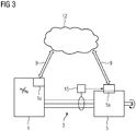
- FIG. 3 shows a further drive system with a decentralized computing unit 12.
- the decentralized computing unit 12 preferably comprises a memory for storing information 9.
- the information 9 for the decentralized computing unit 12 is provided by the first communication module 5a and / or the second communication module 1a.
- the decentralized computing unit 12 may be implemented as a cloud or as an intranet / Internet.
- the consumer 5, designed here as a motor, is connected by the power line 3 to the power source 1, shown here as a frequency converter.
- the consumer 5 comprises the first communication module 1a.
- the current source 1 comprises the second communication module.
- the first communication module 5 a is connected to an energy store 15.
- the energy storage 15 is supplied by the power line 3 with electrical energy.
- the energy storage 15 serves as a collection point of electrical energy, wherein the electrical energy is provided to the first communication module 5a.
- the first communication module 5a has the identifier 7 of the consumer 5 and transmits the identifier 7 at least as part of the information 9 to the decentralized computing unit 12 and / or to the second communication module 1a.
- the invention relates to a method for connecting a drive system and a drive system.
- the drive system comprises a power source 1 and a consumer 5.
- the consumer 5 is connected via a power line 3 to the power source 1.
- the power source 1 provides an analysis signal to the consumer 5 ready.
- information 9 is displayed as to whether the respective current phase u, v, w is connected in accordance with a predetermined terminal assignment 9.
- the consumer 5 optionally has an identifier 7.
- the identifier 7 and / or the connection information 9 are advantageously provided to the power supply 1.
- the power supply 1 based on the respectively connected consumer 5, the current phases u, v, w adjust.
Landscapes
- Physics & Mathematics (AREA)
- General Physics & Mathematics (AREA)
- Control Of Electric Motors In General (AREA)
- Remote Monitoring And Control Of Power-Distribution Networks (AREA)
Priority Applications (2)
| Application Number | Priority Date | Filing Date | Title |
|---|---|---|---|
| EP17194070.3A EP3462192A1 (fr) | 2017-09-29 | 2017-09-29 | Procédé d'installation d'un système d'entraînement et système d'entraînement |
| EP17201111.6A EP3462193A1 (fr) | 2017-09-29 | 2017-11-10 | Procédé d'installation d'un système d'entraînement et système d'entraînement |
Applications Claiming Priority (1)
| Application Number | Priority Date | Filing Date | Title |
|---|---|---|---|
| EP17194070.3A EP3462192A1 (fr) | 2017-09-29 | 2017-09-29 | Procédé d'installation d'un système d'entraînement et système d'entraînement |
Publications (1)
| Publication Number | Publication Date |
|---|---|
| EP3462192A1 true EP3462192A1 (fr) | 2019-04-03 |
Family
ID=60161914
Family Applications (2)
| Application Number | Title | Priority Date | Filing Date |
|---|---|---|---|
| EP17194070.3A Withdrawn EP3462192A1 (fr) | 2017-09-29 | 2017-09-29 | Procédé d'installation d'un système d'entraînement et système d'entraînement |
| EP17201111.6A Withdrawn EP3462193A1 (fr) | 2017-09-29 | 2017-11-10 | Procédé d'installation d'un système d'entraînement et système d'entraînement |
Family Applications After (1)
| Application Number | Title | Priority Date | Filing Date |
|---|---|---|---|
| EP17201111.6A Withdrawn EP3462193A1 (fr) | 2017-09-29 | 2017-11-10 | Procédé d'installation d'un système d'entraînement et système d'entraînement |
Country Status (1)
| Country | Link |
|---|---|
| EP (2) | EP3462192A1 (fr) |
Families Citing this family (1)
| Publication number | Priority date | Publication date | Assignee | Title |
|---|---|---|---|---|
| CN115004540A (zh) * | 2020-01-31 | 2022-09-02 | 索尤若驱动有限及两合公司 | 用于运行驱动系统的设备和方法 |
Citations (4)
| Publication number | Priority date | Publication date | Assignee | Title |
|---|---|---|---|---|
| US20120217921A1 (en) * | 2011-02-24 | 2012-08-30 | Long Wu | Method and system for evaluating electrical connections between an motor controller and motor |
| US20140097859A1 (en) * | 2011-06-14 | 2014-04-10 | Kabushiki Kaisha Yaskawa Denki | Multiaxial motor drive system and multiaxial motor drive device |
| US20150061694A1 (en) * | 2013-09-02 | 2015-03-05 | Lsis Co., Ltd. | Method of detecting state of power cable in inverter system |
| DE102014223052A1 (de) * | 2013-11-19 | 2015-05-21 | Ford Global Technologies, Llc | Fahrzeugdiagnosesystem und Verfahren zur Erkennung falscher Kabelverbindungen |
Family Cites Families (1)
| Publication number | Priority date | Publication date | Assignee | Title |
|---|---|---|---|---|
| DE102010050785B4 (de) | 2010-11-10 | 2015-02-12 | Sma Solar Technology Ag | Verfahren zur Verifizierung einer elektrischen Verbindung in einer Energieerzeugungsanlage |
-
2017
- 2017-09-29 EP EP17194070.3A patent/EP3462192A1/fr not_active Withdrawn
- 2017-11-10 EP EP17201111.6A patent/EP3462193A1/fr not_active Withdrawn
Patent Citations (4)
| Publication number | Priority date | Publication date | Assignee | Title |
|---|---|---|---|---|
| US20120217921A1 (en) * | 2011-02-24 | 2012-08-30 | Long Wu | Method and system for evaluating electrical connections between an motor controller and motor |
| US20140097859A1 (en) * | 2011-06-14 | 2014-04-10 | Kabushiki Kaisha Yaskawa Denki | Multiaxial motor drive system and multiaxial motor drive device |
| US20150061694A1 (en) * | 2013-09-02 | 2015-03-05 | Lsis Co., Ltd. | Method of detecting state of power cable in inverter system |
| DE102014223052A1 (de) * | 2013-11-19 | 2015-05-21 | Ford Global Technologies, Llc | Fahrzeugdiagnosesystem und Verfahren zur Erkennung falscher Kabelverbindungen |
Also Published As
| Publication number | Publication date |
|---|---|
| EP3462193A1 (fr) | 2019-04-03 |
Similar Documents
| Publication | Publication Date | Title |
|---|---|---|
| EP2052807B1 (fr) | Poste de travail de montage | |
| WO2016193362A1 (fr) | Procédé et système de surveillance de stations de charge | |
| DE112017001402T5 (de) | Vorrichtung zum Bestimmen der Degradation von Sekundärbatterien | |
| DE102009018281A1 (de) | Programmierbarer Konverter von CAN-Daten in analoge Signale | |
| WO2020064443A1 (fr) | Mise à jour de micrologiciel par un module de commande centrale d'une station de charge | |
| EP4345555A1 (fr) | Procédé de contrôle assisté par ordinateur et documentation d'une action d'installation d'un utilisateur pour installer des composants d'une machine agencés de manière spatiale | |
| EP3283928A1 (fr) | Procédé de branchement ou de débranchement automatique d'une résistance de communication d'un dispositif hart | |
| EP2701018A1 (fr) | Procédé de paramétrage sécurisé d'un appareil de terrain | |
| DE102019202201A1 (de) | Verfahren und Vorrichtung zum Steuern einer Energieübertragung zwischen einer Ladestation eines elektrischen Versorgungsnetzes und einem Energiespeicher eines elektrischen Fahrzeugbordnetzes | |
| EP3462192A1 (fr) | Procédé d'installation d'un système d'entraînement et système d'entraînement | |
| DE102018216087A1 (de) | Ladestecker und Messsystem | |
| DE102013216129B4 (de) | Hochvoltvorrichtung und externe Wiedergabevorrichtung und System | |
| EP3422027B1 (fr) | Dispositif, procédé, procédé de fabrication pour tester faisceaux de câbles | |
| EP2437228B1 (fr) | Alarme, installation d'alarme et procédé de reconnaissance d'erreurs de lignes de transmission | |
| DE102010012154A1 (de) | Verfahren zum Überprüfen eines Zustands eines Stromkreises eines Kraftfahrzeugs | |
| DE102018131685A1 (de) | Feldgeräteadapter zur drahtlosen Datenübertragung | |
| DE102020131182A1 (de) | Verfahren zum Ermitteln der Verdrahtung und Funktion von Leistungswandlern einer Ladesäule zum Laden von Elektrofahrzeugen | |
| DE102005043489B4 (de) | Automatisierungstechnische Einrichtung | |
| DE102018106940B4 (de) | Messsystem und Verfahren zur verteilten Energiemessung | |
| DE102020212573B4 (de) | Brandmeldezentrale, Anordnung für eine Gebäudeautomatisierung sowie Verfahren | |
| DE102014009709A1 (de) | Verfahren zur analogen Übertragung eines Sensorsignals | |
| EP3899558B1 (fr) | Procédé et dispositif de contrôle | |
| EP4064489A1 (fr) | Installation électrique pourvue d'appareil de protection électronique, unité d'évaluation, ainsi que procédé de fonctionnement d'une installation électrique | |
| DE102021200284A1 (de) | Verfahren zum Analysieren eines Ladevorgangs einer elektrischen Energiespeichereinrichtung mittels einer Ladeeinrichtung | |
| LU102237B1 (de) | Verfahren zum Ermitteln der Verdrahtung und Funktion von Leistungswandlern einer Ladesäule zum Laden von Elektrofahrzeugen |
Legal Events
| Date | Code | Title | Description |
|---|---|---|---|
| PUAI | Public reference made under article 153(3) epc to a published international application that has entered the european phase |
Free format text: ORIGINAL CODE: 0009012 |
|
| AK | Designated contracting states |
Kind code of ref document: A1 Designated state(s): AL AT BE BG CH CY CZ DE DK EE ES FI FR GB GR HR HU IE IS IT LI LT LU LV MC MK MT NL NO PL PT RO RS SE SI SK SM TR |
|
| AX | Request for extension of the european patent |
Extension state: BA ME |
|
| STAA | Information on the status of an ep patent application or granted ep patent |
Free format text: STATUS: THE APPLICATION IS DEEMED TO BE WITHDRAWN |
|
| 18D | Application deemed to be withdrawn |
Effective date: 20191005 |