EP3462532A1 - Leistungsverteiler für antenne, der vier identische orthomode transducer umfasst - Google Patents
Leistungsverteiler für antenne, der vier identische orthomode transducer umfasst Download PDFInfo
- Publication number
- EP3462532A1 EP3462532A1 EP18191406.0A EP18191406A EP3462532A1 EP 3462532 A1 EP3462532 A1 EP 3462532A1 EP 18191406 A EP18191406 A EP 18191406A EP 3462532 A1 EP3462532 A1 EP 3462532A1
- Authority
- EP
- European Patent Office
- Prior art keywords
- power
- splitter
- transducer
- power distributor
- junctions
- Prior art date
- Legal status (The legal status is an assumption and is not a legal conclusion. Google has not performed a legal analysis and makes no representation as to the accuracy of the status listed.)
- Granted
Links
Images




Classifications
-
- H—ELECTRICITY
- H01—ELECTRIC ELEMENTS
- H01P—WAVEGUIDES; RESONATORS, LINES, OR OTHER DEVICES OF THE WAVEGUIDE TYPE
- H01P5/00—Coupling devices of the waveguide type
- H01P5/12—Coupling devices having more than two ports
- H01P5/16—Conjugate devices, i.e. devices having at least one port decoupled from one other port
-
- H—ELECTRICITY
- H01—ELECTRIC ELEMENTS
- H01P—WAVEGUIDES; RESONATORS, LINES, OR OTHER DEVICES OF THE WAVEGUIDE TYPE
- H01P1/00—Auxiliary devices
- H01P1/16—Auxiliary devices for mode selection, e.g. mode suppression or mode promotion; for mode conversion
- H01P1/161—Auxiliary devices for mode selection, e.g. mode suppression or mode promotion; for mode conversion sustaining two independent orthogonal modes, e.g. orthomode transducer
-
- H—ELECTRICITY
- H01—ELECTRIC ELEMENTS
- H01P—WAVEGUIDES; RESONATORS, LINES, OR OTHER DEVICES OF THE WAVEGUIDE TYPE
- H01P3/00—Waveguides; Transmission lines of the waveguide type
- H01P3/02—Waveguides; Transmission lines of the waveguide type with two longitudinal conductors
- H01P3/08—Microstrips; Strip lines
- H01P3/081—Microstriplines
-
- H—ELECTRICITY
- H01—ELECTRIC ELEMENTS
- H01P—WAVEGUIDES; RESONATORS, LINES, OR OTHER DEVICES OF THE WAVEGUIDE TYPE
- H01P5/00—Coupling devices of the waveguide type
- H01P5/12—Coupling devices having more than two ports
-
- H—ELECTRICITY
- H01—ELECTRIC ELEMENTS
- H01P—WAVEGUIDES; RESONATORS, LINES, OR OTHER DEVICES OF THE WAVEGUIDE TYPE
- H01P5/00—Coupling devices of the waveguide type
- H01P5/12—Coupling devices having more than two ports
- H01P5/16—Conjugate devices, i.e. devices having at least one port decoupled from one other port
- H01P5/19—Conjugate devices, i.e. devices having at least one port decoupled from one other port of the junction type
-
- H—ELECTRICITY
- H01—ELECTRIC ELEMENTS
- H01Q—ANTENNAS, i.e. RADIO AERIALS
- H01Q13/00—Waveguide horns or mouths; Slot antennas; Leaky-waveguide antennas; Equivalent structures causing radiation along the transmission path of a guided wave
- H01Q13/02—Waveguide horns
-
- H—ELECTRICITY
- H01—ELECTRIC ELEMENTS
- H01Q—ANTENNAS, i.e. RADIO AERIALS
- H01Q21/00—Antenna arrays or systems
- H01Q21/24—Combinations of antenna units polarised in different directions for transmitting or receiving circularly and elliptically polarised waves or waves linearly polarised in any direction
- H01Q21/245—Combinations of antenna units polarised in different directions for transmitting or receiving circularly and elliptically polarised waves or waves linearly polarised in any direction provided with means for varying the polarisation
Definitions
- the field of the invention is that of compact power splitters bipolarization.
- This type of splitter is used to feed a network of radiating elements from a source emitting in the field of radio frequencies. It can also function as a receiver in the same frequency domain. In this case, the splitter combines several signals received by the network into a single signal.
- the main missions targeted are X-band, Ku-band and Ka-band active antennas for which notions of space and surface efficiency are essential.
- the openings of the radiating elements for these missions are of the order of 2.5 to 3.5 times the emission wavelength. It follows that the use of high surface efficiency cornets for these applications is to be avoided given their size at these radiating aperture sizes.
- An alternative solution is to network metallic radiating elements of smaller openings in order to benefit from their low heights and their very high surface efficiencies. To this end, it is then necessary to provide a power distributor supplying phase and with low losses access to these metal elements. This The splitter must be compact so as not to alter the gain in compactness provided by the use of reduced opening sources.
- PCB printed Circuit Board
- the splitter comprises four identical "twists" and two power distributors, each pair of junctions located in the same plane being connected by the base of said junctions by means of two twists to the two outputs of a power distributor having a single input .
- the splitter comprises a coupler whose input is intended to be connected to the radiofrequency power supply and the two mutually perpendicular outputs being connected to the inputs of the two power distributors, said distributor thus formed being able to generate circularly polarized signals.
- the coupler is a "top-wall” coupler or a Riblet coupler.
- each power distributor has a 180 degree angled input connected to two identical transverse branches, each branch being terminated by a 90 degree elbow connected to an output, so that an input signal propagating in a given direction is separated into two identical output signals propagating in two directions parallel to each other and perpendicular to the given direction.
- the distributor comprises at least one notch filter.
- each twist includes a chamber in the form of a quarter of a flat cylinder, a 90 degree bent inlet and a 90 degree bent outlet, the two elbows being arranged head to tail.
- the side of the square base of each orthomode transducer is approximately 0.75 times the wavelength of use and in that the height of each orthomode transducer is approximately 0.37 times the wavelength of use.
- the side of the square base of the splitter is about 2.24 times the wavelength of use and in that the total height of the splitter is about 0.8 times the wavelength of use.
- the frequency associated with the use wavelength is between 1 and 40 GHz. More specifically, the frequency associated with the use wavelength is between 10.7 and 12.75 GHz or between 17.2 and 20.2 GHz.
- the transducer operates in transmission.
- the same transducer can operate in reception.
- the figure 1 represents a three-dimensional exploded view of a first configuration of the splitter according to the invention.
- This first configuration comprises a coupler of "top-wall” type. This view is oriented in a plane (x, y, z).
- This distributor has several superimposed stages.
- the last floor is the emission stage. It comprises four identical orthomode transducers 10 of metal and of substantially parallelepipedic shape with a square base, each transducer having a lower face 12 and an upper emitting face 11 and four lateral faces 13, the assembly defining a cavity.
- the square base side of each orthomode transducer is about 0.75 times the wavelength of use and the height of each orthomode transducer is about 0.37 times the wavelength of use.
- Each transducer may comprise a central cone-shaped or pyramid-shaped adapter element or cylindrical cylinders. different stacked diameters or parallelepipeds with square bases of different stacked surfaces. The function of these elements is to improve the adaptation of the transducer to a determined operating frequency band and to improve the isolation between two polarizations.
- each transducer has on each of two adjacent lateral faces a metal waveguide connected to the underside of the transducer, the output of said waveguide being through the top of the transducer.
- Each waveguide therefore comprises two elbows separated by a plane guide, a first elbow 16 at 90 degrees connected to the underside of the transducer, a second elbow 17 at 90 degrees located at the top of the transducer.
- the height of a waveguide is close to that of a transducer.
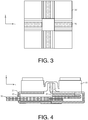
- each transducer is connected to its two neighbors by two T-shaped junctions 20 perpendicular to each other, each junction being connected by the two branches of the T to the vertices of two waveguides, the set of four junctions forming a Greek cross centered on the square of the transducers as seen on the figure 3 .
- Two junctions are arranged along the x-axis and two junctions arranged along the y-axis in this figure. The junctions are junctions called "plane E".
- the bases of the junctions are at the level of the bases of the orthomode transducers as we see on the figure 2 .
- the stage disposed under the upper stage of the distributor is shown in the sectional view of the figure 4 . Its function is to facilitate the injection of the transmission signals into the four junctions. Indeed, as arranged in a cross, it is not convenient to inject phase emission signals inside the junctions.
- This stage comprises four identical twists 30, two power distributors 41 and 42 and the coupler 50. These different elements are represented by different hatching on the figure 4 .
- the figure 5 represents a three-dimensional view of a twist 30 according to the invention.
- Each twist 30 includes an enclosure 31 in the form of a quarter of a flat cylinder, an inlet 32 bent at 90 degrees and an outlet 33 bent at 90 degrees, the two elbows being arranged head to tail.
- the four inputs of the emission signals at the input of the twists are arranged on the sides of the large square formed by the four orthomode transducers so as to form two pairs of two orthogonal inputs between them.
- Each power distributor has a 180 degree angled input connected to two identical transverse branches, each branch being terminated by a 90 degree elbow connected to an output, so that an input signal propagating in a given direction is separated into two identical output signals propagating in two directions parallel to each other and perpendicular to the given direction.
- the paths traveled by the transmission signals are perfectly identical.
- the four orthomode transducers emit four signals in phase with the same polarization.
- the output signals On the opposite input of the second distributor, there is the same property with the difference that the output signals have a linear polarization disposed at 90 degrees from the previous one. All these signals are also in phase.
- the figure 6 represents in top view the propagation of the linear polarization of the signals in the four transducers 10.
- the signals from the first distributor are represented by white arrows and the signals from the second distributor by black arrows.
- the splitter comprises a coupler 50 "top-wall" flat whose input is connected to the radio frequency power source and the two perpendicular outputs between them connected to the inputs of the two power distributors, said splitter thus constituted is suitable generating circularly polarized signals.
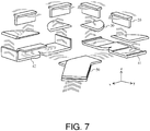
- the figure 7 represents a partial exploded view of such a distributor in the reference (x, y, z). In this view, the orthomode transducers are not shown.
- the propagation of the signal through the different components 20, 30, 41, 42 and 50 of the distributor is represented by gray chevrons.
- the figure 9 represents a third configuration of the splitter according to the invention.
- the power splitter according to the invention includes rejection filters 53 so that the emitted signal does not pollute the reception signal.
- These filters are in the form of regularly spaced metal slits arranged perpendicular to the propagation of the signal.
- the splitters according to the invention can operate in a frequency band of between 1 and 40 GHz, which corresponds to a use wavelength of between 7.5 and 300 millimeters. More precisely, the frequency may belong to the "Ku-Tx" or "Ka-Tx" transmission bands intended for satellite transmissions.
- the Ku-Tx band is between 10.7 and 12.75 GHz, which corresponds to a usage wavelength of between 23 and 28 millimeters.
- the second Ka-Tx band is between 17.2 and 20.2 GHz, which corresponds to a use wavelength of between 15 and 17 millimeters.
- This type of splitter can work with powerful power sources.
- the power of the power source may be greater than 60 watts.
- the geometry of the splitter ensures very low returns on the source of emission, generally lower than -20 dB and very good isolations between the inputs of the coupler "top-wall" and the accesses to the orthomode transducers. These isolations are greater than 20 dB.
Landscapes
- Variable-Direction Aerials And Aerial Arrays (AREA)
Applications Claiming Priority (1)
| Application Number | Priority Date | Filing Date | Title |
|---|---|---|---|
| FR1700993A FR3071672B1 (fr) | 2017-09-28 | 2017-09-28 | Repartiteur de puissance pour antenne comportant quatre transducteurs orthomodes identiques |
Publications (2)
| Publication Number | Publication Date |
|---|---|
| EP3462532A1 true EP3462532A1 (de) | 2019-04-03 |
| EP3462532B1 EP3462532B1 (de) | 2020-10-07 |
Family
ID=61521518
Family Applications (1)
| Application Number | Title | Priority Date | Filing Date |
|---|---|---|---|
| EP18191406.0A Active EP3462532B1 (de) | 2017-09-28 | 2018-08-29 | Leistungsverteiler für antenne, der vier identische orthomode transducer umfasst |
Country Status (5)
| Country | Link |
|---|---|
| US (1) | US10673118B2 (de) |
| EP (1) | EP3462532B1 (de) |
| CN (1) | CN109616729A (de) |
| CA (1) | CA3017113A1 (de) |
| FR (1) | FR3071672B1 (de) |
Families Citing this family (4)
| Publication number | Priority date | Publication date | Assignee | Title |
|---|---|---|---|---|
| FR3089358B1 (fr) | 2018-12-03 | 2022-01-21 | Thales Sa | Elément rayonnant à accès multiples |
| EP3866256B1 (de) | 2020-02-12 | 2023-06-21 | European Space Agency | Wellenleiterleistungsteiler |
| CN112688068B (zh) * | 2020-12-21 | 2021-11-23 | 西安电子科技大学 | 一种小型化的宽带三极化天线 |
| CN113078450B (zh) * | 2021-03-22 | 2022-02-01 | 北京交通大学 | 双极化空气波导阵列天线 |
Citations (5)
| Publication number | Priority date | Publication date | Assignee | Title |
|---|---|---|---|---|
| FR2582865A1 (fr) * | 1985-06-04 | 1986-12-05 | Labo Electronique Physique | Modules unitaires d'antenne hyperfrequences et antenne hyperfrequences comprenant de tels modules |
| EP1930982A1 (de) * | 2006-12-08 | 2008-06-11 | Im, Seung joon | Horngruppenantenne mit zwei linearen Polarisationen |
| WO2014127420A1 (en) * | 2013-02-21 | 2014-08-28 | Bae Systems Australia Ltd | Wideband antenna system and method |
| EP2869400A1 (de) * | 2013-11-04 | 2015-05-06 | Thales | Doppelpolarisierter kompakter Leistungsverteiler, Netz aus mehreren Verteilern, kompaktes Strahlungselement und Flachantenne, die einen solchen Verteiler umfasst |
| EP3179551A1 (de) * | 2015-12-11 | 2017-06-14 | Thales | Kompakteinheit zur doppelpolarisierten ansteuerung für ein strahlungselement einer antenne, und kompaktes netz, das mindestens vier kompakte ansteuerungseinheiten umfasst |
Family Cites Families (4)
| Publication number | Priority date | Publication date | Assignee | Title |
|---|---|---|---|---|
| US7397323B2 (en) * | 2006-07-12 | 2008-07-08 | Wide Sky Technology, Inc. | Orthomode transducer |
| ATE542260T1 (de) * | 2009-02-02 | 2012-02-15 | Centre Nat Etd Spatiales | Orthomoduswandler für einen wellenleiter |
| US9287615B2 (en) * | 2013-03-14 | 2016-03-15 | Raytheon Company | Multi-mode signal source |
| CN205609721U (zh) * | 2016-05-11 | 2016-09-28 | 江苏尚瑞通信科技有限公司 | 一种低损耗的“n”形腔体功分器 |
-
2017
- 2017-09-28 FR FR1700993A patent/FR3071672B1/fr not_active Expired - Fee Related
-
2018
- 2018-08-29 EP EP18191406.0A patent/EP3462532B1/de active Active
- 2018-09-12 CA CA3017113A patent/CA3017113A1/en active Pending
- 2018-09-13 US US16/130,844 patent/US10673118B2/en active Active
- 2018-09-25 CN CN201811114359.6A patent/CN109616729A/zh active Pending
Patent Citations (5)
| Publication number | Priority date | Publication date | Assignee | Title |
|---|---|---|---|---|
| FR2582865A1 (fr) * | 1985-06-04 | 1986-12-05 | Labo Electronique Physique | Modules unitaires d'antenne hyperfrequences et antenne hyperfrequences comprenant de tels modules |
| EP1930982A1 (de) * | 2006-12-08 | 2008-06-11 | Im, Seung joon | Horngruppenantenne mit zwei linearen Polarisationen |
| WO2014127420A1 (en) * | 2013-02-21 | 2014-08-28 | Bae Systems Australia Ltd | Wideband antenna system and method |
| EP2869400A1 (de) * | 2013-11-04 | 2015-05-06 | Thales | Doppelpolarisierter kompakter Leistungsverteiler, Netz aus mehreren Verteilern, kompaktes Strahlungselement und Flachantenne, die einen solchen Verteiler umfasst |
| EP3179551A1 (de) * | 2015-12-11 | 2017-06-14 | Thales | Kompakteinheit zur doppelpolarisierten ansteuerung für ein strahlungselement einer antenne, und kompaktes netz, das mindestens vier kompakte ansteuerungseinheiten umfasst |
Also Published As
| Publication number | Publication date |
|---|---|
| CA3017113A1 (en) | 2019-03-28 |
| FR3071672A1 (fr) | 2019-03-29 |
| US10673118B2 (en) | 2020-06-02 |
| CN109616729A (zh) | 2019-04-12 |
| EP3462532B1 (de) | 2020-10-07 |
| US20190097296A1 (en) | 2019-03-28 |
| FR3071672B1 (fr) | 2019-10-11 |
Similar Documents
| Publication | Publication Date | Title |
|---|---|---|
| EP2869400B1 (de) | Doppelpolarisierter kompakter Leistungsverteiler, Netz aus mehreren Verteilern, kompaktes Strahlungselement und Flachantenne, die einen solchen Verteiler umfasst | |
| EP2869396B1 (de) | Leistungsverteiler, der eine T-Kupplung auf der E-Ebene umfasst, Speisenetzwerk und Antenne, die ein solches Speisenetzwerk umfasst | |
| EP3179551B1 (de) | Kompakteinheit zur doppelpolarisierten ansteuerung für ein strahlungselement einer antenne, und kompaktes netz, das mindestens vier kompakte ansteuerungseinheiten umfasst | |
| EP2202839B1 (de) | Kompakte Speiseeinrichtung zur Erzeugung einer Zirkularpolarisation in einer Antenne und Herstellungsvervahren einer solchen Speiseeinrichtung | |
| EP3462532B1 (de) | Leistungsverteiler für antenne, der vier identische orthomode transducer umfasst | |
| EP2564466B1 (de) | Kompaktes strahlungselement mit hohlraumresonatoren | |
| CA1290449C (fr) | Dispositif d'excitation d'un guide d'onde en polarisation circulaire par une antenne plane | |
| WO2020194270A1 (fr) | Composant radiofréquence comportant plusieurs dispositifs à guide d'onde muni de stries | |
| FR3044832A1 (fr) | Architecture d'antenne active a formation de faisceaux hybride reconfigurable | |
| EP3435480B1 (de) | Antenne mit integrierten verzögerungslinsen im innern eines verteilers auf der basis von wellenleiterteilern mit parallelen platten | |
| FR3062524A1 (fr) | Antenne elementaire a dispositif rayonnant planaire | |
| EP4078728A1 (de) | Doppelpolarisationsantenne | |
| FR3024802A1 (fr) | Source multibande a cornet coaxial avec systemes de poursuite monopulse pour antenne a reflecteur | |
| EP3664214B1 (de) | Mehrfachzugriff strahlelemente | |
| EP3900113B1 (de) | Elementare mikrostreifenantenne und gruppenantenne | |
| EP2654121A1 (de) | Strahlbildungsnetz einer Antenne mit geringem Platzbedarf für kreis- oder kegelstumpfförmiges Antennennetz | |
| EP1152483B1 (de) | Zweiband-Mikrowellenstrahlelement | |
| FR2581268A1 (fr) | Emetteur hyperfrequence de puissance | |
| FR3049393A1 (fr) | Procede d'alimentation d'un guide d'onde radial et dispositif a guide d'onde radial |
Legal Events
| Date | Code | Title | Description |
|---|---|---|---|
| PUAI | Public reference made under article 153(3) epc to a published international application that has entered the european phase |
Free format text: ORIGINAL CODE: 0009012 |
|
| STAA | Information on the status of an ep patent application or granted ep patent |
Free format text: STATUS: THE APPLICATION HAS BEEN PUBLISHED |
|
| AK | Designated contracting states |
Kind code of ref document: A1 Designated state(s): AL AT BE BG CH CY CZ DE DK EE ES FI FR GB GR HR HU IE IS IT LI LT LU LV MC MK MT NL NO PL PT RO RS SE SI SK SM TR |
|
| AX | Request for extension of the european patent |
Extension state: BA ME |
|
| STAA | Information on the status of an ep patent application or granted ep patent |
Free format text: STATUS: REQUEST FOR EXAMINATION WAS MADE |
|
| 17P | Request for examination filed |
Effective date: 20191001 |
|
| RBV | Designated contracting states (corrected) |
Designated state(s): AL AT BE BG CH CY CZ DE DK EE ES FI FR GB GR HR HU IE IS IT LI LT LU LV MC MK MT NL NO PL PT RO RS SE SI SK SM TR |
|
| REG | Reference to a national code |
Ref country code: DE Ref legal event code: R079 Ref document number: 602018008470 Country of ref document: DE Free format text: PREVIOUS MAIN CLASS: H01P0001161000 Ipc: H01P0005080000 |
|
| GRAP | Despatch of communication of intention to grant a patent |
Free format text: ORIGINAL CODE: EPIDOSNIGR1 |
|
| STAA | Information on the status of an ep patent application or granted ep patent |
Free format text: STATUS: GRANT OF PATENT IS INTENDED |
|
| RIC1 | Information provided on ipc code assigned before grant |
Ipc: H01P 5/08 20060101AFI20200512BHEP Ipc: H01P 5/12 20060101ALI20200512BHEP Ipc: H01P 11/00 20060101ALI20200512BHEP |
|
| INTG | Intention to grant announced |
Effective date: 20200612 |
|
| GRAS | Grant fee paid |
Free format text: ORIGINAL CODE: EPIDOSNIGR3 |
|
| GRAA | (expected) grant |
Free format text: ORIGINAL CODE: 0009210 |
|
| STAA | Information on the status of an ep patent application or granted ep patent |
Free format text: STATUS: THE PATENT HAS BEEN GRANTED |
|
| AK | Designated contracting states |
Kind code of ref document: B1 Designated state(s): AL AT BE BG CH CY CZ DE DK EE ES FI FR GB GR HR HU IE IS IT LI LT LU LV MC MK MT NL NO PL PT RO RS SE SI SK SM TR |
|
| REG | Reference to a national code |
Ref country code: GB Ref legal event code: FG4D Free format text: NOT ENGLISH |
|
| REG | Reference to a national code |
Ref country code: CH Ref legal event code: EP Ref country code: AT Ref legal event code: REF Ref document number: 1322132 Country of ref document: AT Kind code of ref document: T Effective date: 20201015 |
|
| REG | Reference to a national code |
Ref country code: IE Ref legal event code: FG4D Free format text: LANGUAGE OF EP DOCUMENT: FRENCH |
|
| REG | Reference to a national code |
Ref country code: DE Ref legal event code: R096 Ref document number: 602018008470 Country of ref document: DE |
|
| REG | Reference to a national code |
Ref country code: NL Ref legal event code: MP Effective date: 20201007 |
|
| REG | Reference to a national code |
Ref country code: AT Ref legal event code: MK05 Ref document number: 1322132 Country of ref document: AT Kind code of ref document: T Effective date: 20201007 |
|
| PG25 | Lapsed in a contracting state [announced via postgrant information from national office to epo] |
Ref country code: PT Free format text: LAPSE BECAUSE OF FAILURE TO SUBMIT A TRANSLATION OF THE DESCRIPTION OR TO PAY THE FEE WITHIN THE PRESCRIBED TIME-LIMIT Effective date: 20210208 Ref country code: RS Free format text: LAPSE BECAUSE OF FAILURE TO SUBMIT A TRANSLATION OF THE DESCRIPTION OR TO PAY THE FEE WITHIN THE PRESCRIBED TIME-LIMIT Effective date: 20201007 Ref country code: FI Free format text: LAPSE BECAUSE OF FAILURE TO SUBMIT A TRANSLATION OF THE DESCRIPTION OR TO PAY THE FEE WITHIN THE PRESCRIBED TIME-LIMIT Effective date: 20201007 Ref country code: NO Free format text: LAPSE BECAUSE OF FAILURE TO SUBMIT A TRANSLATION OF THE DESCRIPTION OR TO PAY THE FEE WITHIN THE PRESCRIBED TIME-LIMIT Effective date: 20210107 Ref country code: GR Free format text: LAPSE BECAUSE OF FAILURE TO SUBMIT A TRANSLATION OF THE DESCRIPTION OR TO PAY THE FEE WITHIN THE PRESCRIBED TIME-LIMIT Effective date: 20210108 |
|
| REG | Reference to a national code |
Ref country code: LT Ref legal event code: MG4D |
|
| PG25 | Lapsed in a contracting state [announced via postgrant information from national office to epo] |
Ref country code: SE Free format text: LAPSE BECAUSE OF FAILURE TO SUBMIT A TRANSLATION OF THE DESCRIPTION OR TO PAY THE FEE WITHIN THE PRESCRIBED TIME-LIMIT Effective date: 20201007 Ref country code: LV Free format text: LAPSE BECAUSE OF FAILURE TO SUBMIT A TRANSLATION OF THE DESCRIPTION OR TO PAY THE FEE WITHIN THE PRESCRIBED TIME-LIMIT Effective date: 20201007 Ref country code: PL Free format text: LAPSE BECAUSE OF FAILURE TO SUBMIT A TRANSLATION OF THE DESCRIPTION OR TO PAY THE FEE WITHIN THE PRESCRIBED TIME-LIMIT Effective date: 20201007 Ref country code: IS Free format text: LAPSE BECAUSE OF FAILURE TO SUBMIT A TRANSLATION OF THE DESCRIPTION OR TO PAY THE FEE WITHIN THE PRESCRIBED TIME-LIMIT Effective date: 20210207 Ref country code: BG Free format text: LAPSE BECAUSE OF FAILURE TO SUBMIT A TRANSLATION OF THE DESCRIPTION OR TO PAY THE FEE WITHIN THE PRESCRIBED TIME-LIMIT Effective date: 20210107 Ref country code: AT Free format text: LAPSE BECAUSE OF FAILURE TO SUBMIT A TRANSLATION OF THE DESCRIPTION OR TO PAY THE FEE WITHIN THE PRESCRIBED TIME-LIMIT Effective date: 20201007 Ref country code: ES Free format text: LAPSE BECAUSE OF FAILURE TO SUBMIT A TRANSLATION OF THE DESCRIPTION OR TO PAY THE FEE WITHIN THE PRESCRIBED TIME-LIMIT Effective date: 20201007 |
|
| PG25 | Lapsed in a contracting state [announced via postgrant information from national office to epo] |
Ref country code: NL Free format text: LAPSE BECAUSE OF FAILURE TO SUBMIT A TRANSLATION OF THE DESCRIPTION OR TO PAY THE FEE WITHIN THE PRESCRIBED TIME-LIMIT Effective date: 20201007 Ref country code: HR Free format text: LAPSE BECAUSE OF FAILURE TO SUBMIT A TRANSLATION OF THE DESCRIPTION OR TO PAY THE FEE WITHIN THE PRESCRIBED TIME-LIMIT Effective date: 20201007 |
|
| REG | Reference to a national code |
Ref country code: DE Ref legal event code: R097 Ref document number: 602018008470 Country of ref document: DE |
|
| PG25 | Lapsed in a contracting state [announced via postgrant information from national office to epo] |
Ref country code: CZ Free format text: LAPSE BECAUSE OF FAILURE TO SUBMIT A TRANSLATION OF THE DESCRIPTION OR TO PAY THE FEE WITHIN THE PRESCRIBED TIME-LIMIT Effective date: 20201007 Ref country code: EE Free format text: LAPSE BECAUSE OF FAILURE TO SUBMIT A TRANSLATION OF THE DESCRIPTION OR TO PAY THE FEE WITHIN THE PRESCRIBED TIME-LIMIT Effective date: 20201007 Ref country code: SM Free format text: LAPSE BECAUSE OF FAILURE TO SUBMIT A TRANSLATION OF THE DESCRIPTION OR TO PAY THE FEE WITHIN THE PRESCRIBED TIME-LIMIT Effective date: 20201007 Ref country code: SK Free format text: LAPSE BECAUSE OF FAILURE TO SUBMIT A TRANSLATION OF THE DESCRIPTION OR TO PAY THE FEE WITHIN THE PRESCRIBED TIME-LIMIT Effective date: 20201007 Ref country code: RO Free format text: LAPSE BECAUSE OF FAILURE TO SUBMIT A TRANSLATION OF THE DESCRIPTION OR TO PAY THE FEE WITHIN THE PRESCRIBED TIME-LIMIT Effective date: 20201007 Ref country code: LT Free format text: LAPSE BECAUSE OF FAILURE TO SUBMIT A TRANSLATION OF THE DESCRIPTION OR TO PAY THE FEE WITHIN THE PRESCRIBED TIME-LIMIT Effective date: 20201007 |
|
| PLBE | No opposition filed within time limit |
Free format text: ORIGINAL CODE: 0009261 |
|
| STAA | Information on the status of an ep patent application or granted ep patent |
Free format text: STATUS: NO OPPOSITION FILED WITHIN TIME LIMIT |
|
| PG25 | Lapsed in a contracting state [announced via postgrant information from national office to epo] |
Ref country code: DK Free format text: LAPSE BECAUSE OF FAILURE TO SUBMIT A TRANSLATION OF THE DESCRIPTION OR TO PAY THE FEE WITHIN THE PRESCRIBED TIME-LIMIT Effective date: 20201007 |
|
| 26N | No opposition filed |
Effective date: 20210708 |
|
| PG25 | Lapsed in a contracting state [announced via postgrant information from national office to epo] |
Ref country code: AL Free format text: LAPSE BECAUSE OF FAILURE TO SUBMIT A TRANSLATION OF THE DESCRIPTION OR TO PAY THE FEE WITHIN THE PRESCRIBED TIME-LIMIT Effective date: 20201007 Ref country code: IT Free format text: LAPSE BECAUSE OF FAILURE TO SUBMIT A TRANSLATION OF THE DESCRIPTION OR TO PAY THE FEE WITHIN THE PRESCRIBED TIME-LIMIT Effective date: 20201007 |
|
| PG25 | Lapsed in a contracting state [announced via postgrant information from national office to epo] |
Ref country code: SI Free format text: LAPSE BECAUSE OF FAILURE TO SUBMIT A TRANSLATION OF THE DESCRIPTION OR TO PAY THE FEE WITHIN THE PRESCRIBED TIME-LIMIT Effective date: 20201007 |
|
| REG | Reference to a national code |
Ref country code: DE Ref legal event code: R119 Ref document number: 602018008470 Country of ref document: DE |
|
| REG | Reference to a national code |
Ref country code: CH Ref legal event code: PL |
|
| PG25 | Lapsed in a contracting state [announced via postgrant information from national office to epo] |
Ref country code: MC Free format text: LAPSE BECAUSE OF FAILURE TO SUBMIT A TRANSLATION OF THE DESCRIPTION OR TO PAY THE FEE WITHIN THE PRESCRIBED TIME-LIMIT Effective date: 20201007 |
|
| REG | Reference to a national code |
Ref country code: BE Ref legal event code: MM Effective date: 20210831 |
|
| PG25 | Lapsed in a contracting state [announced via postgrant information from national office to epo] |
Ref country code: LI Free format text: LAPSE BECAUSE OF NON-PAYMENT OF DUE FEES Effective date: 20210831 Ref country code: CH Free format text: LAPSE BECAUSE OF NON-PAYMENT OF DUE FEES Effective date: 20210831 |
|
| PG25 | Lapsed in a contracting state [announced via postgrant information from national office to epo] |
Ref country code: IS Free format text: LAPSE BECAUSE OF FAILURE TO SUBMIT A TRANSLATION OF THE DESCRIPTION OR TO PAY THE FEE WITHIN THE PRESCRIBED TIME-LIMIT Effective date: 20210207 Ref country code: LU Free format text: LAPSE BECAUSE OF NON-PAYMENT OF DUE FEES Effective date: 20210829 |
|
| PG25 | Lapsed in a contracting state [announced via postgrant information from national office to epo] |
Ref country code: IE Free format text: LAPSE BECAUSE OF NON-PAYMENT OF DUE FEES Effective date: 20210829 Ref country code: DE Free format text: LAPSE BECAUSE OF NON-PAYMENT OF DUE FEES Effective date: 20220301 Ref country code: BE Free format text: LAPSE BECAUSE OF NON-PAYMENT OF DUE FEES Effective date: 20210831 |
|
| GBPC | Gb: european patent ceased through non-payment of renewal fee |
Effective date: 20220829 |
|
| PG25 | Lapsed in a contracting state [announced via postgrant information from national office to epo] |
Ref country code: CY Free format text: LAPSE BECAUSE OF FAILURE TO SUBMIT A TRANSLATION OF THE DESCRIPTION OR TO PAY THE FEE WITHIN THE PRESCRIBED TIME-LIMIT Effective date: 20201007 |
|
| PG25 | Lapsed in a contracting state [announced via postgrant information from national office to epo] |
Ref country code: HU Free format text: LAPSE BECAUSE OF FAILURE TO SUBMIT A TRANSLATION OF THE DESCRIPTION OR TO PAY THE FEE WITHIN THE PRESCRIBED TIME-LIMIT; INVALID AB INITIO Effective date: 20180829 |
|
| PG25 | Lapsed in a contracting state [announced via postgrant information from national office to epo] |
Ref country code: GB Free format text: LAPSE BECAUSE OF NON-PAYMENT OF DUE FEES Effective date: 20220829 |
|
| PG25 | Lapsed in a contracting state [announced via postgrant information from national office to epo] |
Ref country code: MK Free format text: LAPSE BECAUSE OF FAILURE TO SUBMIT A TRANSLATION OF THE DESCRIPTION OR TO PAY THE FEE WITHIN THE PRESCRIBED TIME-LIMIT Effective date: 20201007 |
|
| PG25 | Lapsed in a contracting state [announced via postgrant information from national office to epo] |
Ref country code: MT Free format text: LAPSE BECAUSE OF FAILURE TO SUBMIT A TRANSLATION OF THE DESCRIPTION OR TO PAY THE FEE WITHIN THE PRESCRIBED TIME-LIMIT Effective date: 20201007 |
|
| PGFP | Annual fee paid to national office [announced via postgrant information from national office to epo] |
Ref country code: FR Payment date: 20250721 Year of fee payment: 8 |
|
| PG25 | Lapsed in a contracting state [announced via postgrant information from national office to epo] |
Ref country code: TR Free format text: LAPSE BECAUSE OF FAILURE TO SUBMIT A TRANSLATION OF THE DESCRIPTION OR TO PAY THE FEE WITHIN THE PRESCRIBED TIME-LIMIT Effective date: 20201007 |