EP3462586A1 - Prècharge d'un convertisseur statique à circuit intermédiaire à tension continue au moyen d'une alimentation en énergie auxiliaire - Google Patents
Prècharge d'un convertisseur statique à circuit intermédiaire à tension continue au moyen d'une alimentation en énergie auxiliaire Download PDFInfo
- Publication number
- EP3462586A1 EP3462586A1 EP17194067.9A EP17194067A EP3462586A1 EP 3462586 A1 EP3462586 A1 EP 3462586A1 EP 17194067 A EP17194067 A EP 17194067A EP 3462586 A1 EP3462586 A1 EP 3462586A1
- Authority
- EP
- European Patent Office
- Prior art keywords
- converter
- rectifier
- intermediate circuit
- capacitor
- power supply
- Prior art date
- Legal status (The legal status is an assumption and is not a legal conclusion. Google has not performed a legal analysis and makes no representation as to the accuracy of the status listed.)
- Withdrawn
Links
- 239000003990 capacitor Substances 0.000 claims abstract description 52
- 230000001105 regulatory effect Effects 0.000 claims abstract description 10
- 238000000034 method Methods 0.000 claims abstract description 7
- 239000004065 semiconductor Substances 0.000 claims description 25
- 230000000903 blocking effect Effects 0.000 description 2
- 238000001816 cooling Methods 0.000 description 2
- 230000004907 flux Effects 0.000 description 2
- 238000012544 monitoring process Methods 0.000 description 2
- 230000000712 assembly Effects 0.000 description 1
- 238000000429 assembly Methods 0.000 description 1
- 230000015572 biosynthetic process Effects 0.000 description 1
- 230000001276 controlling effect Effects 0.000 description 1
- 230000001419 dependent effect Effects 0.000 description 1
- 230000005284 excitation Effects 0.000 description 1
- 238000009434 installation Methods 0.000 description 1
- 230000003993 interaction Effects 0.000 description 1
- 230000000630 rising effect Effects 0.000 description 1
- 238000009827 uniform distribution Methods 0.000 description 1
Images


Classifications
-
- H—ELECTRICITY
- H02—GENERATION; CONVERSION OR DISTRIBUTION OF ELECTRIC POWER
- H02M—APPARATUS FOR CONVERSION BETWEEN AC AND AC, BETWEEN AC AND DC, OR BETWEEN DC AND DC, AND FOR USE WITH MAINS OR SIMILAR POWER SUPPLY SYSTEMS; CONVERSION OF DC OR AC INPUT POWER INTO SURGE OUTPUT POWER; CONTROL OR REGULATION THEREOF
- H02M1/00—Details of apparatus for conversion
- H02M1/36—Means for starting or stopping converters
-
- H—ELECTRICITY
- H02—GENERATION; CONVERSION OR DISTRIBUTION OF ELECTRIC POWER
- H02M—APPARATUS FOR CONVERSION BETWEEN AC AND AC, BETWEEN AC AND DC, OR BETWEEN DC AND DC, AND FOR USE WITH MAINS OR SIMILAR POWER SUPPLY SYSTEMS; CONVERSION OF DC OR AC INPUT POWER INTO SURGE OUTPUT POWER; CONTROL OR REGULATION THEREOF
- H02M7/00—Conversion of AC power input into DC power output; Conversion of DC power input into AC power output
- H02M7/02—Conversion of AC power input into DC power output without possibility of reversal
- H02M7/04—Conversion of AC power input into DC power output without possibility of reversal by static converters
- H02M7/06—Conversion of AC power input into DC power output without possibility of reversal by static converters using discharge tubes without control electrode or semiconductor devices without control electrode
- H02M7/062—Avoiding or suppressing excessive transient voltages or currents
-
- H—ELECTRICITY
- H02—GENERATION; CONVERSION OR DISTRIBUTION OF ELECTRIC POWER
- H02M—APPARATUS FOR CONVERSION BETWEEN AC AND AC, BETWEEN AC AND DC, OR BETWEEN DC AND DC, AND FOR USE WITH MAINS OR SIMILAR POWER SUPPLY SYSTEMS; CONVERSION OF DC OR AC INPUT POWER INTO SURGE OUTPUT POWER; CONTROL OR REGULATION THEREOF
- H02M7/00—Conversion of AC power input into DC power output; Conversion of DC power input into AC power output
- H02M7/02—Conversion of AC power input into DC power output without possibility of reversal
- H02M7/04—Conversion of AC power input into DC power output without possibility of reversal by static converters
- H02M7/12—Conversion of AC power input into DC power output without possibility of reversal by static converters using discharge tubes with control electrode or semiconductor devices with control electrode
- H02M7/125—Avoiding or suppressing excessive transient voltages or currents
-
- H—ELECTRICITY
- H02—GENERATION; CONVERSION OR DISTRIBUTION OF ELECTRIC POWER
- H02M—APPARATUS FOR CONVERSION BETWEEN AC AND AC, BETWEEN AC AND DC, OR BETWEEN DC AND DC, AND FOR USE WITH MAINS OR SIMILAR POWER SUPPLY SYSTEMS; CONVERSION OF DC OR AC INPUT POWER INTO SURGE OUTPUT POWER; CONTROL OR REGULATION THEREOF
- H02M1/00—Details of apparatus for conversion
- H02M1/0003—Details of control, feedback or regulation circuits
- H02M1/0006—Arrangements for supplying an adequate voltage to the control circuit of converters
-
- H—ELECTRICITY
- H02—GENERATION; CONVERSION OR DISTRIBUTION OF ELECTRIC POWER
- H02M—APPARATUS FOR CONVERSION BETWEEN AC AND AC, BETWEEN AC AND DC, OR BETWEEN DC AND DC, AND FOR USE WITH MAINS OR SIMILAR POWER SUPPLY SYSTEMS; CONVERSION OF DC OR AC INPUT POWER INTO SURGE OUTPUT POWER; CONTROL OR REGULATION THEREOF
- H02M1/00—Details of apparatus for conversion
- H02M1/0067—Converter structures employing plural converter units, other than for parallel operation of the units on a single load
- H02M1/007—Plural converter units in cascade
-
- H—ELECTRICITY
- H02—GENERATION; CONVERSION OR DISTRIBUTION OF ELECTRIC POWER
- H02M—APPARATUS FOR CONVERSION BETWEEN AC AND AC, BETWEEN AC AND DC, OR BETWEEN DC AND DC, AND FOR USE WITH MAINS OR SIMILAR POWER SUPPLY SYSTEMS; CONVERSION OF DC OR AC INPUT POWER INTO SURGE OUTPUT POWER; CONTROL OR REGULATION THEREOF
- H02M3/00—Conversion of DC power input into DC power output
- H02M3/01—Resonant DC/DC converters
-
- H—ELECTRICITY
- H02—GENERATION; CONVERSION OR DISTRIBUTION OF ELECTRIC POWER
- H02M—APPARATUS FOR CONVERSION BETWEEN AC AND AC, BETWEEN AC AND DC, OR BETWEEN DC AND DC, AND FOR USE WITH MAINS OR SIMILAR POWER SUPPLY SYSTEMS; CONVERSION OF DC OR AC INPUT POWER INTO SURGE OUTPUT POWER; CONTROL OR REGULATION THEREOF
- H02M3/00—Conversion of DC power input into DC power output
- H02M3/02—Conversion of DC power input into DC power output without intermediate conversion into AC
- H02M3/04—Conversion of DC power input into DC power output without intermediate conversion into AC by static converters
- H02M3/10—Conversion of DC power input into DC power output without intermediate conversion into AC by static converters using discharge tubes with control electrode or semiconductor devices with control electrode
- H02M3/145—Conversion of DC power input into DC power output without intermediate conversion into AC by static converters using discharge tubes with control electrode or semiconductor devices with control electrode using devices of a triode or transistor type requiring continuous application of a control signal
- H02M3/155—Conversion of DC power input into DC power output without intermediate conversion into AC by static converters using discharge tubes with control electrode or semiconductor devices with control electrode using devices of a triode or transistor type requiring continuous application of a control signal using semiconductor devices only
- H02M3/156—Conversion of DC power input into DC power output without intermediate conversion into AC by static converters using discharge tubes with control electrode or semiconductor devices with control electrode using devices of a triode or transistor type requiring continuous application of a control signal using semiconductor devices only with automatic control of output voltage or current, e.g. switching regulators
-
- H—ELECTRICITY
- H02—GENERATION; CONVERSION OR DISTRIBUTION OF ELECTRIC POWER
- H02M—APPARATUS FOR CONVERSION BETWEEN AC AND AC, BETWEEN AC AND DC, OR BETWEEN DC AND DC, AND FOR USE WITH MAINS OR SIMILAR POWER SUPPLY SYSTEMS; CONVERSION OF DC OR AC INPUT POWER INTO SURGE OUTPUT POWER; CONTROL OR REGULATION THEREOF
- H02M3/00—Conversion of DC power input into DC power output
- H02M3/22—Conversion of DC power input into DC power output with intermediate conversion into AC
- H02M3/24—Conversion of DC power input into DC power output with intermediate conversion into AC by static converters
- H02M3/28—Conversion of DC power input into DC power output with intermediate conversion into AC by static converters using discharge tubes with control electrode or semiconductor devices with control electrode to produce the intermediate AC
- H02M3/325—Conversion of DC power input into DC power output with intermediate conversion into AC by static converters using discharge tubes with control electrode or semiconductor devices with control electrode to produce the intermediate AC using devices of a triode or a transistor type requiring continuous application of a control signal
- H02M3/335—Conversion of DC power input into DC power output with intermediate conversion into AC by static converters using discharge tubes with control electrode or semiconductor devices with control electrode to produce the intermediate AC using devices of a triode or a transistor type requiring continuous application of a control signal using semiconductor devices only
- H02M3/33538—Conversion of DC power input into DC power output with intermediate conversion into AC by static converters using discharge tubes with control electrode or semiconductor devices with control electrode to produce the intermediate AC using devices of a triode or a transistor type requiring continuous application of a control signal using semiconductor devices only of the forward type
-
- H—ELECTRICITY
- H02—GENERATION; CONVERSION OR DISTRIBUTION OF ELECTRIC POWER
- H02M—APPARATUS FOR CONVERSION BETWEEN AC AND AC, BETWEEN AC AND DC, OR BETWEEN DC AND DC, AND FOR USE WITH MAINS OR SIMILAR POWER SUPPLY SYSTEMS; CONVERSION OF DC OR AC INPUT POWER INTO SURGE OUTPUT POWER; CONTROL OR REGULATION THEREOF
- H02M3/00—Conversion of DC power input into DC power output
- H02M3/22—Conversion of DC power input into DC power output with intermediate conversion into AC
- H02M3/24—Conversion of DC power input into DC power output with intermediate conversion into AC by static converters
- H02M3/28—Conversion of DC power input into DC power output with intermediate conversion into AC by static converters using discharge tubes with control electrode or semiconductor devices with control electrode to produce the intermediate AC
- H02M3/325—Conversion of DC power input into DC power output with intermediate conversion into AC by static converters using discharge tubes with control electrode or semiconductor devices with control electrode to produce the intermediate AC using devices of a triode or a transistor type requiring continuous application of a control signal
- H02M3/335—Conversion of DC power input into DC power output with intermediate conversion into AC by static converters using discharge tubes with control electrode or semiconductor devices with control electrode to produce the intermediate AC using devices of a triode or a transistor type requiring continuous application of a control signal using semiconductor devices only
- H02M3/33569—Conversion of DC power input into DC power output with intermediate conversion into AC by static converters using discharge tubes with control electrode or semiconductor devices with control electrode to produce the intermediate AC using devices of a triode or a transistor type requiring continuous application of a control signal using semiconductor devices only having several active switching elements
- H02M3/33571—Half-bridge at primary side of an isolation transformer
-
- H—ELECTRICITY
- H02—GENERATION; CONVERSION OR DISTRIBUTION OF ELECTRIC POWER
- H02M—APPARATUS FOR CONVERSION BETWEEN AC AND AC, BETWEEN AC AND DC, OR BETWEEN DC AND DC, AND FOR USE WITH MAINS OR SIMILAR POWER SUPPLY SYSTEMS; CONVERSION OF DC OR AC INPUT POWER INTO SURGE OUTPUT POWER; CONTROL OR REGULATION THEREOF
- H02M7/00—Conversion of AC power input into DC power output; Conversion of DC power input into AC power output
- H02M7/02—Conversion of AC power input into DC power output without possibility of reversal
- H02M7/04—Conversion of AC power input into DC power output without possibility of reversal by static converters
- H02M7/12—Conversion of AC power input into DC power output without possibility of reversal by static converters using discharge tubes with control electrode or semiconductor devices with control electrode
- H02M7/145—Conversion of AC power input into DC power output without possibility of reversal by static converters using discharge tubes with control electrode or semiconductor devices with control electrode using devices of a thyratron or thyristor type requiring extinguishing means
- H02M7/155—Conversion of AC power input into DC power output without possibility of reversal by static converters using discharge tubes with control electrode or semiconductor devices with control electrode using devices of a thyratron or thyristor type requiring extinguishing means using semiconductor devices only
- H02M7/162—Conversion of AC power input into DC power output without possibility of reversal by static converters using discharge tubes with control electrode or semiconductor devices with control electrode using devices of a thyratron or thyristor type requiring extinguishing means using semiconductor devices only in a bridge configuration
Definitions
- the invention relates to a power converter with a rectifier, a DC link with at least one DC link capacitor and an auxiliary power supply. Furthermore, the invention relates to a method for precharging at least one intermediate circuit capacitor such converter.
- Voltage intermediate circuits of power converters or frequency converters can not be connected directly to the mains voltage via the rectification because the resulting charging currents would overload components. Therefore, the intermediate circuit is loaded with an additional circuit part at a reduced current and connected only with a correspondingly high DC link voltage directly to the network.
- the pre-charging current for the voltage intermediate circuit is usually reduced by resistors, which are bridged by a contactor or semiconductor after some time or voltage level at the DC link. It is likewise possible to pre-charge the voltage intermediate circuit by means of a step-down converter. In the case of a thyristor rectifier, it is also possible to pre-charge the DC link via phase-angle control.
- auxiliary power supply For the supply of different components in the power converter such as control electronics, control modules and fans in the converter an auxiliary power supply is available. These components are also referred to as auxiliary electronics or generally as auxiliary operations.
- the auxiliary electronics of power converters is supplied by the auxiliary power supply with electrical energy, which the Frequently consumed energy from the voltage source or another network takes.
- the invention has for its object to improve the summons of power converters.
- a power converter with a rectifier, a DC link with at least one DC link capacitor and an auxiliary power supply wherein the auxiliary power supply comprises a buck converter and a voltage generating unit, wherein at the input of the buck converter, a capacitor is arranged, wherein the output of the buck converter with the voltage generating unit via a switching element is connected, wherein the output of the buck converter is connected via a diode to the intermediate circuit, wherein the DC side output of the rectifier is connected via a decoupling element to the intermediate circuit, wherein the DC side output of the rectifier is connected to the input of the buck converter, wherein the Capacitance of the capacitor is less than the capacity of the DC link capacitor.
- the object is achieved by a method for precharging at least one intermediate circuit capacitor of such a converter, wherein by means of the buck converter of the auxiliary power supply, a pre-charging is controlled or regulated by a network connection to at least one DC link capacitor.
- the invention is based on the object that the power supply of the power converter can be used both for the supply of the auxiliary electronics and for pre-charging the DC link.
- the auxiliary power supply must have a buck converter and a voltage generating unit.
- This type of auxiliary power supply is also called a two-stage flux transformer topology.
- a switching element is present at the output of the buck converter. This can be realized for example with a mechanical switch such as a relay or with a semiconductor.
- the subpoena can proceed as follows. First, the DC link is precharged. For this purpose, the step-down converter will work on its current limit until the intermediate circuit has a voltage which is charged at the level of the grid peak value. Thereafter, the pre-charge is switched off state-controlled or time-controlled, whereby the output of the throttle is bridged to the subsequent power supply. In the course of the rectifier can be electrically connected by means of the decoupling element with the intermediate circuit.
- the main advantage is that a circuit part, more precisely the buck converter, can perform two tasks, for which two circuit parts were used in the past. This reduces costs and installation space. Furthermore, the invention provides robustness against a short circuit in the DC link, since this does not necessarily lead to a short-circuiting of the network phases. Also, polarity reversal of several inverters connected via the intermediate circuit or excessive DC link capacitance leads to a behavior which resembles a short circuit (freewheeling diodes of the IGBTs in the forward direction) and can be controlled by the newly proposed arrangement.
- this precharge can therefore be used particularly well, since an interaction of the power converters, for example by simultaneous precharging and a high network load associated with it is reliably avoided.
- the buck converter can now monitor the DC link charging current without additional effort. This can be dispensed with an additional current monitoring, as used in a resistance or Phasenanroughvorladung. Furthermore, it is also possible to dispense with a corresponding switching device for reacting to an impermissible current determined by the current monitoring. In addition to saving costs for the components, the efficiency of the power converter also improves, as these lossy ones can be dispensed with.
- the arrangement according to the invention prepares fewer problems than a thyristor charge with phase control, since this filter experiences little excitation by the step-down converter.
- an undesirable vibration behavior at the power input filter can be reliably avoided.
- the phase control also tends to generate dangerous surges in the grid input filter.
- the proposed circuit can also take over the formation of the intermediate circuit, which is necessary for a longer standstill of the power converter.
- the circuit can then form voltage or current controlled the intermediate circuit.
- the state of the art is that currently the operator of the power converter has cumbersome to create by hand a rising in stages voltage to the DC link.
- the rectifier can be formed for example by a B2 (1-phase) or a B6 bridge circuit (3-phase).
- diodes may be arranged in the bridge branches. It is also possible to use as rectifier a half- or full-controlled bridge circuit with thyristors.
- a power converter with turn-off semiconductors can be used as a rectifier.
- the diodes, which are antiparallel, form arranged to the turn-off switching elements are the rectifier.
- the rectifier has rectifying diodes which are arranged between a mains connection and the input of the buck converter, wherein the rectifier has switchable power semiconductors which are arranged between the mains connection and the intermediate circuit.
- rectifier diodes are used for the rectifier. These need no auxiliary power for a drive, since they need no drive signal in contrast to thyristors to go into the conductive state.
- diodes can be used for the rectification, which serves as an input for the step-down converter, while for the supply of the intermediate circuit, other components, such as other diodes, thyristors or turn-off semiconductor devices, are used. It is particularly advantageous if the semiconductors involved in the precharge need not be controlled. Thus, the precharge can take place even if there is no auxiliary power for controlling these components.
- either the anti-parallel to the switching element of the turn-off semiconductor arranged diodes can be used as rectifying diodes or in addition diodes are provided, which are connected to the input of the buck converter.
- the performance, in particular the current carrying capacity, of the rectifier diodes is lower than that of the switchable power semiconductors. Since the summons with the help of the buck converter can be controlled or regulated, the maximum currents can be easily determined by the controller / regulation. The corresponding rectifier diodes for precharge then require only a low current carrying capacity. Since the pre-charging rarely occurs in operation, these rectifier diodes can also be operated for pre-charging in the overload range, in which a short-term operation is possible without damage. Thus, correspondingly inexpensive diodes can be used as rectifying diodes.
- the decoupling element is designed as a mechanical switch, in particular as a separator.
- a mechanical switch as decoupling element, the connection between rectifier and DC link can be made regardless of the height of the DC link voltage and the mains voltage. This is particularly useful when the rectifier has turn-off semiconductor, since in this case the freewheeling diodes can lead to an uncontrollable charging current.
- the same components as, for example, a B2 or B6 diode bridge are used for the supply of the intermediate circuit and for the precharge, the use of a mechanical switch has proved to be advantageous, since then a direct current flow from the rectifier to the intermediate circuit is reliably avoided during the precharge can be.
- the decoupling element is designed as a diode. If a current flow of the rectifier can be avoided in the intermediate circuit during the precharge, for example by a half- or fully controlled bridge circuit, then a diode can be used as a decoupling element. This requires in contrast to the mechanical switch no logic that determines the required switching state and then passes this to the switch as a switching action.
- the diode also makes it possible that during operation of the converter of the buck converter not only by the stored energy of the capacitor is cushioned, but also the energy of the DC link capacitor is available. This makes the capacitor particularly small dimensions.
- the switching element is designed as a mechanical switch, in particular as a separator.
- the mechanical switch can be set in a simple and cost-effective manner, the operating mode of the auxiliary power supply. While in a first switching position of the buck converter only makes the regulated or controlled pre-charging of the DC link, in the second switching position additionally or alternatively, the voltage generation for the auxiliary power is activated by the voltage generating unit.
- the switching element is designed as a semiconductor switch, in particular as MOSFet.
- MOSFet the semiconductor switch
- the switching element is set in the conductive state after completion of the precharge.
- the voltage generating unit can provide energy for the auxiliary operations. From this point on, the power converter can go into operation because necessary components such as the control of the semiconductor or the cooling of the converter are ready for operation.
- an output voltage of the voltage generating unit is controlled during the pre-charging by means of the semiconductor switch according to claim 6.
- energy can already be made available to auxiliary plants during the precharging of the intermediate circuit capacitor by the voltage generation unit.
- the energy provided in its voltage level by the semiconductor switch is controlled or regulated.
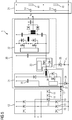
- the FIG. 1 shows a power converter circuit with a pre-charge known from the prior art.
- the power converter has a rectifier 12 and an intermediate circuit 21.
- an intermediate circuit capacitor 14 is arranged in the intermediate circuit 21, an intermediate circuit capacitor 14 is arranged.
- the rectifier 12 consists of a B6 bridge circuit with rectifying diodes 11.
- the intermediate circuit capacitor 14 is pre-charged via the rectifier diodes 11.
- 12 pre-charging resistors 40 are arranged in the supply line between mains connection L1, L2, L3 and rectifier. By this, the pre-charging current is limited and unacceptably high current values that can burden the power grid avoided.
- the precharge resistors 40 are bridged by means of a precharge contactor 50, so that no or at least only slight losses occur during operation.
- the FIG. 2 shows a power converter 1 with a precharge via an auxiliary power supply 30.
- This power converter 1 can be dispensed with the use of precharge resistors 40.
- This power converter 1 also has a rectifier 12 and an intermediate circuit 21.
- the rectifier may be a diode rectifier, a semi-controlled or a fully controlled diode bridge.
- the rectifier 12 may be formed as a self-commutated power converter.
- the intermediate circuit 21 comprises an intermediate circuit capacitor 14.
- the intermediate circuit 21, as shown here also comprise a series connection of a plurality, in particular two intermediate circuit capacitors 14.
- the rectifier 12 also has a B6 rectification circuit, as well as a bridge circuit, in this exemplary embodiment. This may have rectifying diodes 11 in a simple embodiment. Alternatively, it is also possible to provide thyristors instead of individual rectifier diodes 11. Another alternative is to use a self-commutated power converter with turn-off semiconductors as the rectifier 12. As a further component, the power converter 1 has an auxiliary power supply 30.
- the auxiliary power supply 30 includes a buck converter 31 and a voltage generating unit 32.
- the input of the buck converter 37 is connected to the DC-side output 13 of the rectifier 12 is connected.
- a capacitor 35 is arranged there.
- the output 36 of the buck converter is connected via a switching element 33 to the voltage generating unit 32.
- the switching element 33 is designed in this embodiment as a mechanical switch.
- the output 13 of the rectifier 12 is connected to the intermediate circuit 21 via a decoupling element 34.
- the output of the voltage generator unit 32 is the output voltage u H of the voltage generating unit 32 at.
- Via diode 38 through which the precharge current i VL flows the output 36 of the buck converter 31 is connected to the intermediate circuit 21.
- the switching element 33 and the decoupling element 34 are opened.
- the capacitor 35 is charged via the rectifier 12. Due to the comparatively small capacitance of the capacitor 35, the load on the power supply network due to the charging current of the capacitor 35 is so low that no pre-charging resistors are required to limit the pre-charging current.
- a controlled or regulated pre-charging current i VL can be generated, which charges the intermediate circuit capacitors 14 from the power supply network via the network connection L1, L2, L3.
- this precharge current i VL is controlled or regulated by the step-down converter 31, unacceptably high current peaks can thus be avoided in a simple manner.
- the switching element 33 and the decoupling element 34 are closed so that they make a conductive connection. This puts the diode 38 in the blocking state.
- the power converter 1 is then ready for operation.
- the auxiliary power supply 30 can now generate at its output the output voltage u H for the supply of auxiliary plants and thus supply the auxiliary plants with electrical energy.
- FIG. 3 shows a further embodiment of a power converter 1 with a precharge on the auxiliary power supply 30.
- the rectifier 12 has a diode bridge for supplying the buck converter 31.
- the rectifier 12 comprises switchable power semiconductors 15 in the form of thyristors, with which energy can be transmitted from the mains connection L1, L2, L3 into the intermediate circuit 21 after the precharge has been completed.
- a self-commutated power converter as a rectifier 12.
- the freewheeling diodes of the turn-off semiconductor switch then form the rectifying diodes 11 of the rectifier 12.
- decoupling elements 34 a diode is used. Also in this embodiment, the DC link capacitors 14 are controlled by means of the buck converter 31 controlled. Until the completion of the precharge, the diode of the decoupling element 34 is in the blocking state. Only when the intermediate circuit capacitors 14 are charged, the diode 34 of the decoupling element 34 is conductive and the entire DC link capacity is available for the operation of the auxiliary power supply 30. With this auxiliary power supply 30, the auxiliary power can be supplied with electrical energy via the output voltage u H.
- FIG. 4 shows a further embodiment of a power converter 1 with a precharge on the auxiliary power supply 30.
- a switching element 33 a semiconductor switch is used instead of a mechanical switch.
- a possible semiconductor switch for this application is a MOSFet. With this semiconductor switch, it is possible to generate a controlled or regulated output voltage u H at the output of the voltage generating unit 32 already during the precharging of the intermediate circuit capacitor 14. In this case, the semiconductor switch of the switching element 33 serves as an actuator to affect the output voltage u H.
- the auxiliary operations of the power converter 1 can be supplied with electrical energy.
- FIG. 5 shows a further embodiment of a power converter 1 with a precharge on the auxiliary power supply 30.
- the auxiliary power supply 30 is constructed in mirror image with respect to the potentials of the intermediate circuit 21. Even with this arrangement, the same advantages as in the previously described embodiments can be produced.
- the invention relates to a power converter, comprising a rectifier, a DC link with at least one DC link capacitor and an auxiliary power supply.
- the auxiliary power supply comprises a buck converter and a voltage generating unit, wherein a capacitor is arranged at the input of the buck converter, wherein the output of the buck converter is connected to the voltage generating unit via a switching element, wherein the output of the buck converter via a diode with the DC link is connected, wherein a DC side output of the rectifier is connected via a decoupling element to the intermediate circuit, wherein the DC side output of the rectifier is connected to the input of the buck converter, wherein the capacitance of the capacitor is less than the capacitance of the DC link capacitor.
- the invention relates to a method for pre-charging at least an intermediate circuit capacitor of such a power converter, wherein by means of the buck converter of the auxiliary power supply, a pre-charging current is controlled or regulated by a network connection to the at least one intermediate circuit capacitor.
Landscapes
- Engineering & Computer Science (AREA)
- Power Engineering (AREA)
- Dc-Dc Converters (AREA)
Priority Applications (2)
| Application Number | Priority Date | Filing Date | Title |
|---|---|---|---|
| EP17194067.9A EP3462586A1 (fr) | 2017-09-29 | 2017-09-29 | Prècharge d'un convertisseur statique à circuit intermédiaire à tension continue au moyen d'une alimentation en énergie auxiliaire |
| PCT/EP2018/072648 WO2019063214A1 (fr) | 2017-09-29 | 2018-08-22 | Précharge d'un circuit intermédiaire de la tension du convertisseur de puissance au moyen d'une alimentation en énergie auxiliaire |
Applications Claiming Priority (1)
| Application Number | Priority Date | Filing Date | Title |
|---|---|---|---|
| EP17194067.9A EP3462586A1 (fr) | 2017-09-29 | 2017-09-29 | Prècharge d'un convertisseur statique à circuit intermédiaire à tension continue au moyen d'une alimentation en énergie auxiliaire |
Publications (1)
| Publication Number | Publication Date |
|---|---|
| EP3462586A1 true EP3462586A1 (fr) | 2019-04-03 |
Family
ID=59997256
Family Applications (1)
| Application Number | Title | Priority Date | Filing Date |
|---|---|---|---|
| EP17194067.9A Withdrawn EP3462586A1 (fr) | 2017-09-29 | 2017-09-29 | Prècharge d'un convertisseur statique à circuit intermédiaire à tension continue au moyen d'une alimentation en énergie auxiliaire |
Country Status (2)
| Country | Link |
|---|---|
| EP (1) | EP3462586A1 (fr) |
| WO (1) | WO2019063214A1 (fr) |
Cited By (3)
| Publication number | Priority date | Publication date | Assignee | Title |
|---|---|---|---|---|
| CN113339132A (zh) * | 2021-06-30 | 2021-09-03 | 重庆华世丹动力科技股份有限公司 | 便于直流发电机低转速启动的辅助电源 |
| EP4178103A1 (fr) * | 2021-11-09 | 2023-05-10 | Hilti Aktiengesellschaft | Outil électrique pouvant être géré par réseau |
| WO2023124117A1 (fr) * | 2021-12-31 | 2023-07-06 | 圣邦微电子(北京)股份有限公司 | Circuit et procédé de conversion de puissance |
Families Citing this family (1)
| Publication number | Priority date | Publication date | Assignee | Title |
|---|---|---|---|---|
| DE102024206907A1 (de) * | 2024-07-23 | 2026-01-29 | Siemens Aktiengesellschaft | Stromrichter mit Hilfsspannungsversorgung |
Citations (4)
| Publication number | Priority date | Publication date | Assignee | Title |
|---|---|---|---|---|
| DE9216662U1 (de) * | 1992-12-07 | 1993-01-28 | Siemens AG, 80333 München | Vorladeschaltung mit kombiniertem Überspannungsschutz für einen netzgeführten Stromrichter mit ausgangsseitigem Kondensator |
| JP2000116131A (ja) * | 1998-10-01 | 2000-04-21 | Yaskawa Electric Corp | 電力変換装置 |
| EP2325985A2 (fr) * | 2009-11-20 | 2011-05-25 | Diehl AKO Stiftung & Co. KG | Circuit et procédé de préparation d'une alimentation de tension pour un étage de commande |
| EP2533409A1 (fr) | 2011-06-10 | 2012-12-12 | Siemens Aktiengesellschaft | Convertisseur de fréquence doté d'un dispositif de limitation de courant et procédé de fonctionnement de celui-ci |
-
2017
- 2017-09-29 EP EP17194067.9A patent/EP3462586A1/fr not_active Withdrawn
-
2018
- 2018-08-22 WO PCT/EP2018/072648 patent/WO2019063214A1/fr not_active Ceased
Patent Citations (4)
| Publication number | Priority date | Publication date | Assignee | Title |
|---|---|---|---|---|
| DE9216662U1 (de) * | 1992-12-07 | 1993-01-28 | Siemens AG, 80333 München | Vorladeschaltung mit kombiniertem Überspannungsschutz für einen netzgeführten Stromrichter mit ausgangsseitigem Kondensator |
| JP2000116131A (ja) * | 1998-10-01 | 2000-04-21 | Yaskawa Electric Corp | 電力変換装置 |
| EP2325985A2 (fr) * | 2009-11-20 | 2011-05-25 | Diehl AKO Stiftung & Co. KG | Circuit et procédé de préparation d'une alimentation de tension pour un étage de commande |
| EP2533409A1 (fr) | 2011-06-10 | 2012-12-12 | Siemens Aktiengesellschaft | Convertisseur de fréquence doté d'un dispositif de limitation de courant et procédé de fonctionnement de celui-ci |
Cited By (4)
| Publication number | Priority date | Publication date | Assignee | Title |
|---|---|---|---|---|
| CN113339132A (zh) * | 2021-06-30 | 2021-09-03 | 重庆华世丹动力科技股份有限公司 | 便于直流发电机低转速启动的辅助电源 |
| EP4178103A1 (fr) * | 2021-11-09 | 2023-05-10 | Hilti Aktiengesellschaft | Outil électrique pouvant être géré par réseau |
| WO2023083615A1 (fr) * | 2021-11-09 | 2023-05-19 | Hilti Aktiengesellschaft | Outil électrique commandable par réseau |
| WO2023124117A1 (fr) * | 2021-12-31 | 2023-07-06 | 圣邦微电子(北京)股份有限公司 | Circuit et procédé de conversion de puissance |
Also Published As
| Publication number | Publication date |
|---|---|
| WO2019063214A1 (fr) | 2019-04-04 |
Similar Documents
| Publication | Publication Date | Title |
|---|---|---|
| EP2432109B1 (fr) | Commutateur modulaire pour un convertisseur électrique, convertisseur électrique et procédé de fonctionnement d'un convertisseur électrique | |
| DE102008032876B4 (de) | Verfahren, Schaltungsanordnung und Brückenschaltung | |
| EP3028376B1 (fr) | Convertisseur-élévateur, onduleur correspondant et procédé de fonctionnement | |
| CH698835B1 (de) | Eigenstromversorgung für Stromrichterschaltertreiber. | |
| EP2255434A1 (fr) | Procédé de commande d'un redresseur de courant à phases multiples avec des réservoirs d'énergie distribués, à basses fréquences de sortie | |
| DE102020214013A1 (de) | Leistungswandler, steuerverfahren und steuerprogramm | |
| EP2596980B1 (fr) | Convertisseur de courant à plusieurs points avec hacheur de freinage | |
| EP2299572A1 (fr) | Démarrage d'un convertisseur CC/CC avec un transformateur à haute fréquence | |
| EP2709257A2 (fr) | Circuit de convertisseur de courant et procédé de commande du circuit de convertisseur de courant | |
| EP0166954A1 (fr) | Procédé pour la réduction des surtensions dynamiques dans un réseau de courant alternatif | |
| EP3462586A1 (fr) | Prècharge d'un convertisseur statique à circuit intermédiaire à tension continue au moyen d'une alimentation en énergie auxiliaire | |
| DE69210940T2 (de) | Leistungsumrichter | |
| DE1961195A1 (de) | Wechselrichterschaltung | |
| CH693523A5 (de) | Einrichtung zur Begrenzung der Aenderungsgeschwindigkeit der ausgangsseitigen Spannung eines selbstgeführten mehrphasigen Umrichters. | |
| DE102007013462A1 (de) | Leistungselektronische Schaltungsanordnung für eine Drehfeldmaschine | |
| DE10338476A1 (de) | Spannungszwischenkreis-Umrichter | |
| WO2009156021A1 (fr) | Circuit transformateur de tension et onduleur | |
| EP2733837A1 (fr) | Convertisseur | |
| EP2826126B1 (fr) | Dispositif électronique de puissance comportant une symétrisation d'un n ud de tension dans le circuit intermédiaire | |
| DE102012206801A1 (de) | Schaltung mit einer stromrichterschaltung und verfahren zur leistungsanpassung | |
| EP3882067A1 (fr) | Véhicule, en particulier véhicule ferroviaire | |
| DE19825801C2 (de) | Gleichspannungs-Zwischenkreis mit Hochlast-Widerstand | |
| EP0474060A2 (fr) | Convertisseur de courant alternatif à quatre quadrants | |
| EP3035514A1 (fr) | Dispositif de préchargement d'un convertisseur | |
| DE102013109714A1 (de) | Verfahren zum Betreiben einer elektrischen Schaltung sowie elektrische Schaltung |
Legal Events
| Date | Code | Title | Description |
|---|---|---|---|
| PUAI | Public reference made under article 153(3) epc to a published international application that has entered the european phase |
Free format text: ORIGINAL CODE: 0009012 |
|
| AK | Designated contracting states |
Kind code of ref document: A1 Designated state(s): AL AT BE BG CH CY CZ DE DK EE ES FI FR GB GR HR HU IE IS IT LI LT LU LV MC MK MT NL NO PL PT RO RS SE SI SK SM TR |
|
| AX | Request for extension of the european patent |
Extension state: BA ME |
|
| STAA | Information on the status of an ep patent application or granted ep patent |
Free format text: STATUS: THE APPLICATION IS DEEMED TO BE WITHDRAWN |
|
| 18D | Application deemed to be withdrawn |
Effective date: 20191005 |