EP3462635B1 - Procédé de fonctionnement d'un système de communication - Google Patents
Procédé de fonctionnement d'un système de communication Download PDFInfo
- Publication number
- EP3462635B1 EP3462635B1 EP17194149.5A EP17194149A EP3462635B1 EP 3462635 B1 EP3462635 B1 EP 3462635B1 EP 17194149 A EP17194149 A EP 17194149A EP 3462635 B1 EP3462635 B1 EP 3462635B1
- Authority
- EP
- European Patent Office
- Prior art keywords
- receiver
- ground
- ground receivers
- receivers
- group
- Prior art date
- Legal status (The legal status is an assumption and is not a legal conclusion. Google has not performed a legal analysis and makes no representation as to the accuracy of the status listed.)
- Active
Links
Images


Classifications
-
- H—ELECTRICITY
- H04—ELECTRIC COMMUNICATION TECHNIQUE
- H04B—TRANSMISSION
- H04B7/00—Radio transmission systems, i.e. using radiation field
- H04B7/14—Relay systems
- H04B7/15—Active relay systems
- H04B7/185—Space-based or airborne stations; Stations for satellite systems
- H04B7/1853—Satellite systems for providing telephony service to a mobile station, i.e. mobile satellite service
- H04B7/18532—Arrangements for managing transmission, i.e. for transporting data or a signalling message
-
- H—ELECTRICITY
- H04—ELECTRIC COMMUNICATION TECHNIQUE
- H04B—TRANSMISSION
- H04B1/00—Details of transmission systems, not covered by a single one of groups H04B3/00 - H04B13/00; Details of transmission systems not characterised by the medium used for transmission
- H04B1/69—Spread spectrum techniques
- H04B1/707—Spread spectrum techniques using direct sequence modulation
- H04B1/7097—Interference-related aspects
-
- H—ELECTRICITY
- H04—ELECTRIC COMMUNICATION TECHNIQUE
- H04B—TRANSMISSION
- H04B17/00—Monitoring; Testing
- H04B17/30—Monitoring; Testing of propagation channels
- H04B17/309—Measuring or estimating channel quality parameters
- H04B17/336—Signal-to-interference ratio [SIR] or carrier-to-interference ratio [CIR]
-
- H—ELECTRICITY
- H04—ELECTRIC COMMUNICATION TECHNIQUE
- H04B—TRANSMISSION
- H04B7/00—Radio transmission systems, i.e. using radiation field
- H04B7/02—Diversity systems; Multi-antenna system, i.e. transmission or reception using multiple antennas
- H04B7/04—Diversity systems; Multi-antenna system, i.e. transmission or reception using multiple antennas using two or more spaced independent antennas
- H04B7/0413—MIMO systems
- H04B7/0452—Multi-user MIMO systems
-
- H—ELECTRICITY
- H04—ELECTRIC COMMUNICATION TECHNIQUE
- H04B—TRANSMISSION
- H04B7/00—Radio transmission systems, i.e. using radiation field
- H04B7/14—Relay systems
- H04B7/15—Active relay systems
- H04B7/185—Space-based or airborne stations; Stations for satellite systems
-
- H—ELECTRICITY
- H04—ELECTRIC COMMUNICATION TECHNIQUE
- H04B—TRANSMISSION
- H04B7/00—Radio transmission systems, i.e. using radiation field
- H04B7/14—Relay systems
- H04B7/15—Active relay systems
- H04B7/185—Space-based or airborne stations; Stations for satellite systems
- H04B7/18523—Satellite systems for providing broadcast service to terrestrial stations, i.e. broadcast satellite service
- H04B7/18526—Arrangements for data linking, networking or transporting, or for controlling an end to end session
-
- H—ELECTRICITY
- H04—ELECTRIC COMMUNICATION TECHNIQUE
- H04B—TRANSMISSION
- H04B7/00—Radio transmission systems, i.e. using radiation field
- H04B7/14—Relay systems
- H04B7/15—Active relay systems
- H04B7/204—Multiple access
- H04B7/2041—Spot beam multiple access
Definitions
- the invention relates to a method for operating a communication system, the communication system comprising transmitting antennas for transmitting symbol streams and ground receivers which may be provided with the symbol streams transmitted by the transmitting antennas, the transmitting antennas being located with a distance from Earth, and the ground receivers spatially separated from each other.
- Contemporary high throughput satellites are the consequence of a constantly increasing demand for high data rates provided by satellites.
- SATCOM satellite communication
- frequency reuse techniques are an effective strategy to enhance the total capacity of a single satellite.
- spot beams are used to illuminate a specific service zone on Earth instead of using a single beam for the same area.
- Several of the in-orbit HTSs deploy a so-called four color scheme, ensuring different frequencies or polarizations for adjacent spot beams.
- Recent frequency reuse patterns so-called aggressive frequency reuse schemes, even use the same frequency band and polarization in neighboring beams.
- CCI co-channel interference
- the downlink part (from the satellite to the receivers on Earth) of the forward link (FL) represents a multi-user multiple-input multiple-output (MU-MIMO) system.
- MU-MIMO multi-user multiple-input multiple-output
- every ground terminal receives the signals from its dedicated satellite beam antenna as well as from satellite antennas illuminating adjacent service zones.
- a common transmitter technique to mitigate this interference is a joint preprocessing of the transmit signals of all antennas as described in D. Christopoulos, S. Chatzinotas, and B. Ottersten, "User scheduling for coordinated dual satellite systems with linear precoding," in IEEE International Conference on Communications, 2013, pp. 4498-4503 .
- Scheduling algorithms can be divided into two classes, which are user selection and user grouping as described in X. Yi and E. K. S. Au, "User scheduling for heterogeneous multiuser MIMO systems: A subspace viewpoint," IEEE Transactions on Vehicular Technology, vol. 60, no. 8, pp. 4004-4013, 2011 .
- User selection searches for only a single subset of all available users for scheduling. This is often necessary when the upper performance bound of a system is investigated where only the 'best' users, e.g. in terms of sum rate, should be selected.
- FSS fixed satellite services
- user selection algorithms have a limited relevance because the channel between satellite and receiver is nearly constant and only influenced by long-term fading effects, e.g. caused by rain. Hence, a user selection algorithm would select always the same users over a long period while the remaining users are starving.
- user grouping algorithms schedule all users into groups which are served consecutively. The segmentation into groups can be done with respect to different fairness criteria. For SATCOM user grouping algorithms are of greater interest because a satellite provider generally aims at serving all of his customers, not only those with the best channel conditions.
- the transmitting antennas may be of different types.
- the transmitting antenna may be of a reflector type which is fed by single feed or by an array of feeds.
- the assigning of the further ground receiver to a respective receiver group may be performed based on different aspects.
- the respective further ground receiver is assigned to that receiver group in which the lowest metric value between the further ground receiver and the ground receivers already assigned to this group is highest compared with the other receiver groups.
- the respective further ground receiver is assigned to that receiver group which, after the addition of the further ground receiver, achieves the best metric value as a group.
- the method further comprises the following method step:
- Interferences are due to the fact that all transmitting antennas and all ground receivers use the same frequency and that each ground receiver receives a linear combination of the symbol streams. Such interferences may be addressed by precoding.
- precoding may be performed on the basis of inversion of the channel matrix of a receiver group or on the basis of a method according to A. Wiesel, S. Member, Y. C. Eldar, S. Member, and S. S. Shitz, "Zero- Forcing Precoding and Generalized Inverses," vol. 56, no. 9, pp. 4409- 4418, 2008 .
- precoding of the symbol streams for the ground receivers is performed on the Earth, i.e. before the symbol streams are sent from the Earth to the transmitting antennas or at a distance from Earth, e.g. on a satellite where the transmitting antennas are located.
- a new empty receiver group is generated and the respective further ground receiver is assigned to this new receiver group when the addition of the respective further ground receiver to an existing receiver group the metric value does not exceed a predefined threshold value.
- a metric value the dot product of the linear combinations, or a modification of the dot product of the linear combinations, or an orthogonal projection of the linear combinations, or the signal-to-interference-and-noise-ratio, or the signal-over-leakage capacity
- the sum rate or the channel capacity is used which is yielded when all channel information of one receiver group together with the other receiver groups are combined to one channel matrix.
- the number of V i ground receivers which are assigned to the receiver groups first are those ground receivers which comprise a linear combination the norm of which is highest.
- the number of V i ground receivers which are assigned to the receiver groups first are those ground receivers which comprise a linear combination the norm of which is lowest.
- the number of E of empty receiver groups is chosen as an integer wherein the constraint E ⁇ K/N applies.
- Determining the linear combinations between the transmit antennas and the ground receivers may be performed in different ways. However, according to a preferred embodiment of the invention, for determining the linear combinations between the N transmit antennas and each of the K ground receivers the position of the N transmitting antennas and the position of the K ground receivers is determined and/or a channel estimation method is applied.
- the ground receivers do not exchange data with each other.
- the transmitting antennas are satellite based. Even more preferably, the transmitting antennas are based on a single satellite in space.
- the transmitting antennas are located on a high-altitude platform station.
- a preferred embodiment of the invention may apply according to which at least one satellite and at least one high-altitude platform station are used in combination for locating the transmit antennas.
- VOD video-on-demand
- the ground receivers are located on earth on a respective fixed position or located on earth stations on mobile platforms.
- the term "earth stations on mobile platform” especially refers to the possibility for providing broadband connectivity to passengers on board moving vehicles, including aircrafts, ships and trains.
- N R reflectors are fed by N F feeds in total (N F /N R feeds per reflector), which leads to N F spot beams on the ground. Adjacent coverage areas are illuminated by different reflectors.
- a satellite architecture that utilizes multiple multi-beam antennas to illuminate the coverage zone is already used by satellites in orbit according to the Eutelsat HTS system.
- Fig. 1 schematically illustrates the beam and reflector setup according to the preferred embodiment of the invention.
- the Arabic numerals inside the spot beams SB indicate the source reflector.
- the source feeds are marked by the letters a to d.
- the individual link between the N F feeds and a single user on the ground represents a Multiple-Input Single-Output (MISO) channel.
- MISO Multiple-Input Single-Output
- K sel users K sel ⁇ N F
- SDMA space division multiple access
- TDMA time division multiple access
- a MU-MIMO system performs if all users have to be scheduled. So instead of finding a single subset the preferred embodiment of the invention focuses on finding disjoint subsets or rather groups. This procedure is known as user grouping and ensures that every user is scheduled exactly once within a scheduling period. In every user group T there can be served up to N F users at the same time.
- the grouping of the users is performed in a greedy manner. To decide which users can be co-scheduled and served together within a common time slot via SDMA, their spatial compatibility is evaluated. According to the preferred embodiment of the invention, an appropriate metric is selected in accordance with the channel model in order to provide a reliable forecast of the channel capacity or throughput.
- the metric according to the preferred embodiment of the invention in the envisaged scenario takes into account two major aspects: The orthogonality of the channel matrix H and the individual channel gains, i.e. the entries of H. To obtain an orthogonal channel matrix, the spacing between the receivers on Earth must be adequate.
- CoC coefficient of correlation
- CoC CoC
- ⁇ ⁇ -orthogonal user groups.
- CoC calculated for all combinations of members inside a group, does not exceed a certain threshold ⁇ . Therefore, a lower limit of orthogonality between all the user channels of a common group is ensured. Users are grouped together and served via SDMA only if the orthogonality of the user channels among themselves exceeds a certain threshold.
- the optimal value for ⁇ depends on the channel characteristics and is identified through computer simulations.
- the method according to the present invention can be summarized as follows: Within the initialization phase the minimum number of required groups N G is identified and the groups are created. In the next step, the users with the largest vector norm are selected to be the first user of each group. Because of the imperfect orthogonality within a user group, the achievable signal-to-interference-plus-noise-ratio decreases with every additional user of a group when zero forcing precoding is used. To avoid that the users with the strongest channel gains mutually influence each other, these users are separated in different groups at startup. During the main part of the method, for every selected user that group is selected where this user has the lowest impact to the orthogonality of the group, otherwise a new group for that user is created. These steps are repeated until all users are scheduled.
- a method for operating a communication system comprising a number of N transmitting antennas TA for transmitting symbol streams SST (indicated by arrows with dashed lines in Fig. 3 ) and a number of K ground receivers GR which may be provided with the symbol streams SST transmitted by the transmitting antennas TA.
- the transmitting antennas TA are located with a distance from Earth E together on one single satellite S, and the ground receivers GR are located on Earth E and spatially separated from each other.
- K and N the constraint K > N applies.
- a respective setup is schematically depicted in Fig. 3 .
- N symbol streams SST are transmitted by the N transmitting antennas TA.
- step S2 a linear combination of the N simultaneously transmitted symbol streams SST is received by each ground receiver GR, respectively.
- step S3 the respective linear combination for the N transmitting antennas TA and each of the K ground receivers GR are determined, respectively.
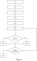
- step 4.1 a number of E empty receiver groups is generated.
- step 4.2 one single ground receiver GR is assigned to each receiver group, respectively, in a totally randomly fashion. Then, on the basis of the metric function mentioned above which delivers metric value CoC, it is examined for all ground receivers GR which have not yet been assigned to a receiver group how a respective further ground receiver GR can be combined with the ground receivers GR which have already been assigned to a respective receiver group in order to achieve better data throughput for the symbol streams SST compared with an assignment of the ground receivers GR to the respective receiver groups which is purely random.
- step S5.1 for a further ground receiver GR which is to be assigned to a receiver group next, the lowest metric values between the further ground receiver and the ground receivers already assigned to this group are determined for all receiver groups. Then, it is checked for which group these lowest metric value of a respective ground receiver (GR) is highest.
- step 5.2 it is checked in step 5.2 whether this metric value (highest member of the lowest metric values throughout the groups) exceeds a predefined threshold value T. If this is the case, the further ground receiver GR which is to be assigned to a receiver group next, is assigned to the receiver group which comprises that ground receiver GR which comprisses above mentioned highest member of the lowest metric values throughout the groups in step 5.3. However, in case this metric value does not exceed the predefined threshold value T, a new empty receiver group is generated in step 5.4 and the respective further ground receiver GR is assigend to this new receiver group. Then, in step 5.5 it is checked whether all ground receivers GR have already been assigend to a receiver group. If this is the case, the assignment method ends. If this is not the case, the method goes back to step 5.1 and is repeated until the last unassigned ground receiver GR has been assigned to a receiver group.
- T a predefined threshold value
Landscapes
- Engineering & Computer Science (AREA)
- Computer Networks & Wireless Communication (AREA)
- Signal Processing (AREA)
- Physics & Mathematics (AREA)
- Astronomy & Astrophysics (AREA)
- Aviation & Aerospace Engineering (AREA)
- General Physics & Mathematics (AREA)
- Computing Systems (AREA)
- Quality & Reliability (AREA)
- Electromagnetism (AREA)
- Mobile Radio Communication Systems (AREA)
- Radio Relay Systems (AREA)
Claims (15)
- Procédé d'exploitation d'un système de communication, le système de communication comprend un nombre N d'antennes de transmission (TA) pour transmettre des flux de symboles (SST) et un nombre K de récepteurs au sol (GR) qui peuvent être alimentés avec les flux de symboles (SST) transmis par les antennes de transmission (TA), les antennes de transmission (TA) étant localisées à distance par rapport à la Terre (E), et les récepteurs au sol (GR) étant séparés les uns des autres dans l'espace, où K ≥ N, le procédé comprenant les étapes de procédé suivantes :- la transmission simultanée de N flux de symboles (SST) par les N antennes de transmission (TA),- la réception d'une combinaison linéaire de N flux de symboles (SST) transmis simultanément par chaque récepteur au sol (GR) respectivement,- la détermination de la combinaison linéaire respective pour les N antennes de transmission (TA) et chacun des K récepteurs au sol (GR), respectivement,- la décision, sur la base des combinaisons linéaires déterminées, de quel parmi les K récepteurs au sol (GR) est associé à un groupe de récepteurs commun respectif afin d'être approvisionné avec des flux de symboles (SST) simultanément et avec la même fréquence, en- générant un nombre E de groupes de récepteurs vides,- associant un récepteur au sol (GR) respectif à un groupe de récepteurs respectif jusqu'à ce que les groupes de récepteurs comprennent chacun un nombre prédéterminé Vi de récepteurs au sol (GR),- après que chaque groupe de récepteurs soit composé de Vi récepteurs au sol (GR), sur la base d'une fonction métrique qui produit une valeur métrique, l'examen pour tous les récepteurs au sol (GR) qui n'ont pas encore été associés à un groupe de récepteurs, à l'exception d'un nombre de M récepteurs au sol (GR) maximal, comment un nouveau récepteur (GR) respectif peut être combiné avec les récepteurs au sol (GR) qui ont déjà été associés à un groupe de récepteurs respectif afin de réaliser une meilleure sortie de données pour les flux de symboles (SST) comparativement à une association des récepteurs au sol (GR) aux groupes de récepteurs respectifs qui est purement aléatoire, en- déterminant la valeur métrique la plus faible entre le nouveau récepteur au sol (GR) et les récepteurs au sol déjà associés à ce groupe pour tous les groupes de récepteurs,- vérifiant pour quel groupe cette valeur métrique la plus faible d'un récepteur au sol (GR) respectif (GR) est la plus élevée,- vérifiant si la valeur métrique qui est l'élément le plus élevé parmi les valeurs métriques les plus faibles dans les groupes dépasse une valeur de seuil (T) prédéfinie, et- associant le nouveau récepteur au sol (Gr) respectif à ce groupe pour lequel la valeur métrique la plus faible déterminée est la plus élevée si la valeur métrique dépasse la valeur de seuil (T) prédéfinie ou en générant un nouveau groupe de récepteurs vide et en associant le nouveau récepteur au sol (GR) respectif à ce nouveau groupe de récepteurs si la valeur métrique ne dépasse pas la valeur de seuil (T) prédéfinie, respectivement, et- associant les autres M récepteurs au sol (GR) maximaux à un groupe de récepteurs respectif sans examiner sur la base de la fonction métrique jusqu'à ce que tous les récepteurs au sol (GR) soient associés à un groupe de récepteurs respectif.
- Procédé selon la revendication 1, dans lequel toutes les antennes de transmission (TA) et tous les récepteurs au sol (GR) utilisent la même fréquence.
- Procédé selon la revendication 2, comprenant l'étape de procédé suivante :- la transmission de flux de symboles (SST) vers tous les récepteurs au sol (GR) d'un groupe de récepteurs respectif, en- précodant les flux de symboles (SST) pour tous les récepteurs au sol (GR) d'un groupe de récepteurs respectif afin de réduire des interférences au niveau des récepteurs au sol (GR) respectifs,- envoyant les flux de symboles précodés aux N antennes de transmission (TA), et- transmettant les flux de symboles (SST) précodés à partir des N antennes de transmission (TA) vers les récepteurs au sol.
- Procédé selon la revendication 3, comprenant l'étape de procédé suivante :- le précodage des flux de symboles (SST)) pour les récepteurs au sol (GR) sur la Terre (E) ou à une distance à partir de la Terre (E).
- Procédé selon l'une quelconque des revendications précédentes, dans lequel, en tant que valeur métrique, le produit scalaire de combinaisons linéaires, ou une modification du produit scalaire des combinaisons linéaires, ou une projection orthogonale des combinaisons linéaires, ou le ratio signal sur interférence et bruit, ou la capacité de dépassement du signal de fuite, ou le taux global ou la capacité du canal, est utilisé, qui est obtenu lorsque toutes les informations de canal d'un groupe de récepteurs conjointement avec les autres groupes de récepteurs sont combinées en une matrice de canal.
- Procédé selon l'une quelconque des revendications précédentes, dans lequel on applique la contrainte Vi = 1.
- Procédé selon l'une quelconque des revendications précédentes, dans lequel le nombre Vi groupes récepteurs (GR) qui est associé aux groupes de récepteurs en premier, est associé aux groupes récepteurs d'une manière purement aléatoire.
- Procédé selon l'une quelconque des revendications 1 à 6, dans lequel le nombre Vi de récepteurs au sol (GR) qui sont associés aux groupes de récepteurs en premier, sont ces récepteurs au sol (GR) qui comprennent une combinaison linéaire dont la norme est la plus élevée.
- Procédé selon l'une quelconque des revendications 1 à 6, dans lequel le nombre Vi de récepteurs au sol (GR) qui sont associés aux groupes de récepteurs en premier, sont ces récepteurs au sol (GR) qui comprennent une combinaison linéaire dont la norme est la plus faible.
- Procédé selon l'une quelconque des revendications précédentes, dans lequel le nombre E de groupes de récepteurs vides est choisi comme un nombre entier avec la contrainte que E ≥ K/N s'applique.
- Procédé selon l'une quelconque des revendications précédentes, dans lequel, pour déterminer les combinaisons linéaires entre les N antennes de transmission (TA) et chacun des K récepteurs au sol (GR), la position des N antennes de transmission (TA) et la position des K récepteurs au sol (GR) est déterminée et/ou une méthode d'estimation de canal est appliquée.
- Procédé selon l'une quelconque des revendications précédentes, dans lequel les récepteurs au sol (GR) n'échangent pas de données les uns avec les autres.
- Procédé selon l'une quelconque des revendications précédentes, dans lequel les antennes de transmission (TA) sont à base de satellites.
- Procédé selon l'une quelconque des revendications précédentes, dans lequel les antennes de transmission (TA) sont situées sur une station de plateforme à haute altitude.
- Procédé selon l'une quelconque des revendications précédentes, dans lequel les récepteurs au sol (GR) sont situés sur terre à une position fixe respective ou situés sur des stations terrestres sur des plateformes mobiles.
Priority Applications (3)
| Application Number | Priority Date | Filing Date | Title |
|---|---|---|---|
| EP17194149.5A EP3462635B1 (fr) | 2017-09-29 | 2017-09-29 | Procédé de fonctionnement d'un système de communication |
| HUE17194149A HUE062270T2 (hu) | 2017-09-29 | 2017-09-29 | Kommunikációs rendszer üzemeltetési módszere |
| US16/202,981 US11025336B2 (en) | 2017-09-29 | 2018-11-28 | Method for operating a communication system |
Applications Claiming Priority (1)
| Application Number | Priority Date | Filing Date | Title |
|---|---|---|---|
| EP17194149.5A EP3462635B1 (fr) | 2017-09-29 | 2017-09-29 | Procédé de fonctionnement d'un système de communication |
Publications (3)
| Publication Number | Publication Date |
|---|---|
| EP3462635A1 EP3462635A1 (fr) | 2019-04-03 |
| EP3462635C0 EP3462635C0 (fr) | 2023-06-07 |
| EP3462635B1 true EP3462635B1 (fr) | 2023-06-07 |
Family
ID=60019711
Family Applications (1)
| Application Number | Title | Priority Date | Filing Date |
|---|---|---|---|
| EP17194149.5A Active EP3462635B1 (fr) | 2017-09-29 | 2017-09-29 | Procédé de fonctionnement d'un système de communication |
Country Status (3)
| Country | Link |
|---|---|
| US (1) | US11025336B2 (fr) |
| EP (1) | EP3462635B1 (fr) |
| HU (1) | HUE062270T2 (fr) |
Families Citing this family (1)
| Publication number | Priority date | Publication date | Assignee | Title |
|---|---|---|---|---|
| EP3484067B1 (fr) * | 2017-11-13 | 2021-01-27 | NEOSAT GmbH | Procédé de fonctionnement d'un système de communication |
Family Cites Families (6)
| Publication number | Priority date | Publication date | Assignee | Title |
|---|---|---|---|---|
| US20030125040A1 (en) * | 2001-11-06 | 2003-07-03 | Walton Jay R. | Multiple-access multiple-input multiple-output (MIMO) communication system |
| US8059733B2 (en) * | 2006-12-20 | 2011-11-15 | Nec Laboratories America, Inc. | Multi-user downlink linear MIMO precoding systems |
| EP2317809B1 (fr) * | 2009-10-29 | 2013-07-03 | Telefonaktiebolaget L M Ericsson (Publ) | Planification des transmissions de liaison montante d'un système de communication sans fil |
| US9980267B2 (en) * | 2016-05-06 | 2018-05-22 | Bridgewest Finance Llc | Unmanned aerial vehicle (UAV) beam pointing and data rate optimization for high throughput broadband access |
| WO2017196098A1 (fr) * | 2016-05-11 | 2017-11-16 | 엘지전자(주) | Procédé d'émission et de réception d'informations d'état de canal dans un système de communications sans fil à antennes multiples, et appareil associé |
| US10645704B2 (en) * | 2017-06-15 | 2020-05-05 | Qualcomm Incorporated | Multi-user multiple-input/multiple-output transmissions in millimeter wave systems |
-
2017
- 2017-09-29 EP EP17194149.5A patent/EP3462635B1/fr active Active
- 2017-09-29 HU HUE17194149A patent/HUE062270T2/hu unknown
-
2018
- 2018-11-28 US US16/202,981 patent/US11025336B2/en active Active
Also Published As
| Publication number | Publication date |
|---|---|
| US11025336B2 (en) | 2021-06-01 |
| EP3462635C0 (fr) | 2023-06-07 |
| US20190222301A1 (en) | 2019-07-18 |
| HUE062270T2 (hu) | 2023-10-28 |
| EP3462635A1 (fr) | 2019-04-03 |
Similar Documents
| Publication | Publication Date | Title |
|---|---|---|
| Kisseleff et al. | Radio resource management techniques for multibeam satellite systems | |
| EP1929691B1 (fr) | Procédé d'allocation de réssources pour OFDM MIMO de systèmes d'accés multi-utilisateurs | |
| Storek et al. | Fair user grouping for multibeam satellites with MU-MIMO precoding | |
| US8750885B2 (en) | Interference mitigation method in cellular system based on orthogonal frequency division multiple access | |
| US8254328B2 (en) | Scheduling method for multi-user MIMO in which resource blocks are allocated based on priorities | |
| EP1542419B1 (fr) | Procédé d'allocation de canaux avec multiplexage spatial dans un système de multiplexage par répartition orthogonale de la fréquence avec plusieurs antennes | |
| US8730883B2 (en) | Coordinated transmission method, coordinated transmission system, central station and radio base station | |
| EP1748579B1 (fr) | Système de communication par radio, méthode de communication par radio, dispositif de station de base et dispositif terminal | |
| JP4776685B2 (ja) | 無線通信システムおよび通信制御方法 | |
| US20080260051A1 (en) | Method and apparatus for transmitting information simultaneously to multiple destinations over shared wireless resources | |
| JP2009105893A (ja) | Mimo無線通信システム | |
| WO2010018690A1 (fr) | Dispositif station de base et dispositif terminal | |
| EP1564906B1 (fr) | Dispositif et procédé d'émission et de réception de données dans un système MIMO multi-utilisateurs | |
| US8243677B2 (en) | Scheduler and method for allocating time and frequency dimensions of downlink bursts in broadband wireless access networks | |
| Ramírez et al. | Resource management in the multibeam NOMA-based satellite downlink | |
| US11025336B2 (en) | Method for operating a communication system | |
| US20080205260A1 (en) | System and method for transmitting data bursts in communication systems | |
| US12368500B2 (en) | Precoded rate-splitting with multiple set-wise common streams for aggressive frequency reuse in a satellite communication system | |
| Vázouez et al. | Closed-form multicast precoding for satellite flexible payloads | |
| Makki et al. | On the throughput of the return-link multi-beam satellite systems using genetic algorithm-based schedulers | |
| Panajotović et al. | Optimal pair-wise SUS scheduling algorithm for multiuser MIMO | |
| Dimitrov et al. | Radio resource management for forward and return links in high throughput satellite systems | |
| Jo | Codebook‐Based Precoding for SDMA‐OFDMA with Spectrum Sharing | |
| Panajotovic et al. | Multiuser Multiple-input Multiple-output Orthogonal Frequency Division Multiplex-ing (MU-MIMO-OFDM) System | |
| Driouch et al. | A graph theory based scheduling algorithm for MIMO-CDMA systems using zero forcing beamforming |
Legal Events
| Date | Code | Title | Description |
|---|---|---|---|
| PUAI | Public reference made under article 153(3) epc to a published international application that has entered the european phase |
Free format text: ORIGINAL CODE: 0009012 |
|
| STAA | Information on the status of an ep patent application or granted ep patent |
Free format text: STATUS: THE APPLICATION HAS BEEN PUBLISHED |
|
| AK | Designated contracting states |
Kind code of ref document: A1 Designated state(s): AL AT BE BG CH CY CZ DE DK EE ES FI FR GB GR HR HU IE IS IT LI LT LU LV MC MK MT NL NO PL PT RO RS SE SI SK SM TR |
|
| AX | Request for extension of the european patent |
Extension state: BA ME |
|
| STAA | Information on the status of an ep patent application or granted ep patent |
Free format text: STATUS: REQUEST FOR EXAMINATION WAS MADE |
|
| 17P | Request for examination filed |
Effective date: 20191004 |
|
| RBV | Designated contracting states (corrected) |
Designated state(s): AL AT BE BG CH CY CZ DE DK EE ES FI FR GB GR HR HU IE IS IT LI LT LU LV MC MK MT NL NO PL PT RO RS SE SI SK SM TR |
|
| STAA | Information on the status of an ep patent application or granted ep patent |
Free format text: STATUS: EXAMINATION IS IN PROGRESS |
|
| 17Q | First examination report despatched |
Effective date: 20200925 |
|
| RAP1 | Party data changed (applicant data changed or rights of an application transferred) |
Owner name: NEOSAT GMBH |
|
| GRAP | Despatch of communication of intention to grant a patent |
Free format text: ORIGINAL CODE: EPIDOSNIGR1 |
|
| STAA | Information on the status of an ep patent application or granted ep patent |
Free format text: STATUS: GRANT OF PATENT IS INTENDED |
|
| INTG | Intention to grant announced |
Effective date: 20220909 |
|
| GRAS | Grant fee paid |
Free format text: ORIGINAL CODE: EPIDOSNIGR3 |
|
| GRAA | (expected) grant |
Free format text: ORIGINAL CODE: 0009210 |
|
| STAA | Information on the status of an ep patent application or granted ep patent |
Free format text: STATUS: THE PATENT HAS BEEN GRANTED |
|
| AK | Designated contracting states |
Kind code of ref document: B1 Designated state(s): AL AT BE BG CH CY CZ DE DK EE ES FI FR GB GR HR HU IE IS IT LI LT LU LV MC MK MT NL NO PL PT RO RS SE SI SK SM TR |
|
| REG | Reference to a national code |
Ref country code: GB Ref legal event code: FG4D |
|
| REG | Reference to a national code |
Ref country code: CH Ref legal event code: EP Ref country code: AT Ref legal event code: REF Ref document number: 1577924 Country of ref document: AT Kind code of ref document: T Effective date: 20230615 |
|
| REG | Reference to a national code |
Ref country code: DE Ref legal event code: R096 Ref document number: 602017069382 Country of ref document: DE |
|
| U01 | Request for unitary effect filed |
Effective date: 20230621 |
|
| U07 | Unitary effect registered |
Designated state(s): AT BE BG DE DK EE FI FR IT LT LU LV MT NL PT SE SI Effective date: 20230627 |
|
| REG | Reference to a national code |
Ref country code: LT Ref legal event code: MG9D |
|
| U20 | Renewal fee for the european patent with unitary effect paid |
Year of fee payment: 7 Effective date: 20230920 |
|
| REG | Reference to a national code |
Ref country code: HU Ref legal event code: AG4A Ref document number: E062270 Country of ref document: HU |
|
| PG25 | Lapsed in a contracting state [announced via postgrant information from national office to epo] |
Ref country code: NO Free format text: LAPSE BECAUSE OF FAILURE TO SUBMIT A TRANSLATION OF THE DESCRIPTION OR TO PAY THE FEE WITHIN THE PRESCRIBED TIME-LIMIT Effective date: 20230907 Ref country code: ES Free format text: LAPSE BECAUSE OF FAILURE TO SUBMIT A TRANSLATION OF THE DESCRIPTION OR TO PAY THE FEE WITHIN THE PRESCRIBED TIME-LIMIT Effective date: 20230607 |
|
| PG25 | Lapsed in a contracting state [announced via postgrant information from national office to epo] |
Ref country code: RS Free format text: LAPSE BECAUSE OF FAILURE TO SUBMIT A TRANSLATION OF THE DESCRIPTION OR TO PAY THE FEE WITHIN THE PRESCRIBED TIME-LIMIT Effective date: 20230607 Ref country code: HR Free format text: LAPSE BECAUSE OF FAILURE TO SUBMIT A TRANSLATION OF THE DESCRIPTION OR TO PAY THE FEE WITHIN THE PRESCRIBED TIME-LIMIT Effective date: 20230607 Ref country code: GR Free format text: LAPSE BECAUSE OF FAILURE TO SUBMIT A TRANSLATION OF THE DESCRIPTION OR TO PAY THE FEE WITHIN THE PRESCRIBED TIME-LIMIT Effective date: 20230908 |
|
| PG25 | Lapsed in a contracting state [announced via postgrant information from national office to epo] |
Ref country code: SK Free format text: LAPSE BECAUSE OF FAILURE TO SUBMIT A TRANSLATION OF THE DESCRIPTION OR TO PAY THE FEE WITHIN THE PRESCRIBED TIME-LIMIT Effective date: 20230607 |
|
| PG25 | Lapsed in a contracting state [announced via postgrant information from national office to epo] |
Ref country code: IS Free format text: LAPSE BECAUSE OF FAILURE TO SUBMIT A TRANSLATION OF THE DESCRIPTION OR TO PAY THE FEE WITHIN THE PRESCRIBED TIME-LIMIT Effective date: 20231007 |
|
| PG25 | Lapsed in a contracting state [announced via postgrant information from national office to epo] |
Ref country code: SM Free format text: LAPSE BECAUSE OF FAILURE TO SUBMIT A TRANSLATION OF THE DESCRIPTION OR TO PAY THE FEE WITHIN THE PRESCRIBED TIME-LIMIT Effective date: 20230607 Ref country code: SK Free format text: LAPSE BECAUSE OF FAILURE TO SUBMIT A TRANSLATION OF THE DESCRIPTION OR TO PAY THE FEE WITHIN THE PRESCRIBED TIME-LIMIT Effective date: 20230607 Ref country code: RO Free format text: LAPSE BECAUSE OF FAILURE TO SUBMIT A TRANSLATION OF THE DESCRIPTION OR TO PAY THE FEE WITHIN THE PRESCRIBED TIME-LIMIT Effective date: 20230607 Ref country code: IS Free format text: LAPSE BECAUSE OF FAILURE TO SUBMIT A TRANSLATION OF THE DESCRIPTION OR TO PAY THE FEE WITHIN THE PRESCRIBED TIME-LIMIT Effective date: 20231007 Ref country code: CZ Free format text: LAPSE BECAUSE OF FAILURE TO SUBMIT A TRANSLATION OF THE DESCRIPTION OR TO PAY THE FEE WITHIN THE PRESCRIBED TIME-LIMIT Effective date: 20230607 |
|
| PG25 | Lapsed in a contracting state [announced via postgrant information from national office to epo] |
Ref country code: PL Free format text: LAPSE BECAUSE OF FAILURE TO SUBMIT A TRANSLATION OF THE DESCRIPTION OR TO PAY THE FEE WITHIN THE PRESCRIBED TIME-LIMIT Effective date: 20230607 |
|
| REG | Reference to a national code |
Ref country code: DE Ref legal event code: R097 Ref document number: 602017069382 Country of ref document: DE |
|
| PLBE | No opposition filed within time limit |
Free format text: ORIGINAL CODE: 0009261 |
|
| STAA | Information on the status of an ep patent application or granted ep patent |
Free format text: STATUS: NO OPPOSITION FILED WITHIN TIME LIMIT |
|
| REG | Reference to a national code |
Ref country code: CH Ref legal event code: PL |
|
| 26N | No opposition filed |
Effective date: 20240308 |
|
| PG25 | Lapsed in a contracting state [announced via postgrant information from national office to epo] |
Ref country code: MC Free format text: LAPSE BECAUSE OF FAILURE TO SUBMIT A TRANSLATION OF THE DESCRIPTION OR TO PAY THE FEE WITHIN THE PRESCRIBED TIME-LIMIT Effective date: 20230607 |
|
| REG | Reference to a national code |
Ref country code: IE Ref legal event code: MM4A |
|
| PG25 | Lapsed in a contracting state [announced via postgrant information from national office to epo] |
Ref country code: IE Free format text: LAPSE BECAUSE OF NON-PAYMENT OF DUE FEES Effective date: 20230929 |
|
| PG25 | Lapsed in a contracting state [announced via postgrant information from national office to epo] |
Ref country code: CH Free format text: LAPSE BECAUSE OF NON-PAYMENT OF DUE FEES Effective date: 20230930 |
|
| PG25 | Lapsed in a contracting state [announced via postgrant information from national office to epo] |
Ref country code: IE Free format text: LAPSE BECAUSE OF NON-PAYMENT OF DUE FEES Effective date: 20230929 Ref country code: CH Free format text: LAPSE BECAUSE OF NON-PAYMENT OF DUE FEES Effective date: 20230930 |
|
| U20 | Renewal fee for the european patent with unitary effect paid |
Year of fee payment: 8 Effective date: 20240925 |
|
| PG25 | Lapsed in a contracting state [announced via postgrant information from national office to epo] |
Ref country code: CY Free format text: LAPSE BECAUSE OF FAILURE TO SUBMIT A TRANSLATION OF THE DESCRIPTION OR TO PAY THE FEE WITHIN THE PRESCRIBED TIME-LIMIT; INVALID AB INITIO Effective date: 20170929 |
|
| PGFP | Annual fee paid to national office [announced via postgrant information from national office to epo] |
Ref country code: HU Payment date: 20250922 Year of fee payment: 9 Ref country code: GB Payment date: 20250919 Year of fee payment: 9 |
|
| U20 | Renewal fee for the european patent with unitary effect paid |
Year of fee payment: 9 Effective date: 20250924 |
|
| PG25 | Lapsed in a contracting state [announced via postgrant information from national office to epo] |
Ref country code: TR Free format text: LAPSE BECAUSE OF FAILURE TO SUBMIT A TRANSLATION OF THE DESCRIPTION OR TO PAY THE FEE WITHIN THE PRESCRIBED TIME-LIMIT Effective date: 20230607 |