EP3462794A1 - Techniques permettant de commander des réseaux de communication - Google Patents
Techniques permettant de commander des réseaux de communication Download PDFInfo
- Publication number
- EP3462794A1 EP3462794A1 EP17194170.1A EP17194170A EP3462794A1 EP 3462794 A1 EP3462794 A1 EP 3462794A1 EP 17194170 A EP17194170 A EP 17194170A EP 3462794 A1 EP3462794 A1 EP 3462794A1
- Authority
- EP
- European Patent Office
- Prior art keywords
- serving
- entity
- entities
- serving entities
- communication
- Prior art date
- Legal status (The legal status is an assumption and is not a legal conclusion. Google has not performed a legal analysis and makes no representation as to the accuracy of the status listed.)
- Withdrawn
Links
Images





Classifications
-
- H—ELECTRICITY
- H04—ELECTRIC COMMUNICATION TECHNIQUE
- H04W—WIRELESS COMMUNICATION NETWORKS
- H04W72/00—Local resource management
- H04W72/50—Allocation or scheduling criteria for wireless resources
- H04W72/52—Allocation or scheduling criteria for wireless resources based on load
-
- H—ELECTRICITY
- H04—ELECTRIC COMMUNICATION TECHNIQUE
- H04W—WIRELESS COMMUNICATION NETWORKS
- H04W24/00—Supervisory, monitoring or testing arrangements
- H04W24/08—Testing, supervising or monitoring using real traffic
-
- H—ELECTRICITY
- H04—ELECTRIC COMMUNICATION TECHNIQUE
- H04W—WIRELESS COMMUNICATION NETWORKS
- H04W72/00—Local resource management
- H04W72/12—Wireless traffic scheduling
-
- H—ELECTRICITY
- H04—ELECTRIC COMMUNICATION TECHNIQUE
- H04W—WIRELESS COMMUNICATION NETWORKS
- H04W72/00—Local resource management
- H04W72/20—Control channels or signalling for resource management
- H04W72/29—Control channels or signalling for resource management between an access point and the access point controlling device
-
- H—ELECTRICITY
- H04—ELECTRIC COMMUNICATION TECHNIQUE
- H04W—WIRELESS COMMUNICATION NETWORKS
- H04W72/00—Local resource management
- H04W72/50—Allocation or scheduling criteria for wireless resources
- H04W72/54—Allocation or scheduling criteria for wireless resources based on quality criteria
- H04W72/543—Allocation or scheduling criteria for wireless resources based on quality criteria based on requested quality, e.g. QoS
-
- H—ELECTRICITY
- H04—ELECTRIC COMMUNICATION TECHNIQUE
- H04W—WIRELESS COMMUNICATION NETWORKS
- H04W16/00—Network planning, e.g. coverage or traffic planning tools; Network deployment, e.g. resource partitioning or cells structures
- H04W16/24—Cell structures
- H04W16/26—Cell enhancers or enhancement, e.g. for tunnels, building shadow
-
- H—ELECTRICITY
- H04—ELECTRIC COMMUNICATION TECHNIQUE
- H04W—WIRELESS COMMUNICATION NETWORKS
- H04W80/00—Wireless network protocols or protocol adaptations to wireless operation
- H04W80/02—Data link layer protocols
-
- H—ELECTRICITY
- H04—ELECTRIC COMMUNICATION TECHNIQUE
- H04W—WIRELESS COMMUNICATION NETWORKS
- H04W84/00—Network topologies
- H04W84/02—Hierarchically pre-organised networks, e.g. paging networks, cellular networks, WLAN [Wireless Local Area Network] or WLL [Wireless Local Loop]
- H04W84/04—Large scale networks; Deep hierarchical networks
- H04W84/042—Public Land Mobile systems, e.g. cellular systems
- H04W84/047—Public Land Mobile systems, e.g. cellular systems using dedicated repeater stations
Definitions
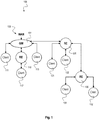
- Fig. 1 is a schematic diagram illustrating a multi-layered wireless communication network 100 according to an exemplary aspect of the present disclosure.
- the control entity can be configured to receive clients and other measurements information from the access points (gateway) 101 and the REs 110, 120, 130 and provide management packets to the access points (gateway) 101 and the REs 110, 120, 130.
- the control entity can use a secured in-band signaling protocol between the access points (gateway 101) and the REs 110, 120, 130 to exchange the measurement information and management packets.
- the multi-layered wireless communication network 200 represents an IEEE 802.11 standards compliant implementation of a WLAN SON 802.11 based network, in particular a network that involves multiple layers of second level serving devices (e.g. RE) deployment.
- a WLAN SON 802.11 based network in particular a network that involves multiple layers of second level serving devices (e.g. RE) deployment.
- RE second level serving devices
- routing and channel assignment is optimized. For example, the traffic of client 3.2.1, 221 assigned to RE2, 220 due to better radio performance, passes 3 wireless links to the GW 201, meaning it may consume 3x air resources. It may be that connecting it via RE1, 210 with a higher path loss is more spectral effective.
- Each system e.g. GW 201 and RE 210, 220 in the topology models a L2 queue hierarchy at each of the egress interfaces, Wi-Fi in the case of REs 210, 220 and WAN (e.g. DSL, GPON, Ethernet and LTE) in the case of GW 201, with the intent to control the in and out flow rates of those L2 per TID/AC queues in real time.
- a combination of strict priority (e.g. for high priority traffic like Video) and Weighted Fair L2 Queueing (e.g. for non-high priority traffic like internet browsing data) scheduler algorithms can be attached to the L2 queues to ensure appropriate resource allocation by balance between service prioritization and fairness.
- the control entity or offer entity can understand the topology and the real time traffic situation and can manage the dynamic configuration of the L2 queues.
- Fig. 3 is a schematic diagram illustrating a multi-layered wireless communication network 300 with connectivity entities and clients according to an exemplary aspect of the present disclosure.
- the multi-layered wireless communication network 300 has a similar network topology as the multi-layered wireless communication network 200 described above with respect to Fig. 2 or as the communication network 100 described above with respect to Fig. 1 .
- the network elements may have the same functionalities as described above with respect to Figs. 1 and 2 .
- the multi-layered wireless communication network 300 represents an IEEE 802.11 standards compliant implementation of a WLAN SON 802.11 based network, in particular a network that involves multiple layers of RE deployment.
- the multi-layered wireless communication network 300 is hierarchically structured with an exemplary number of four hierarchy levels as shown in Fig. 3 .
- a first connectivity entity 301 e.g. a GW 201 as described in Fig. 2 is positioned on a first hierarchy level.
- other connectivity entities 310, 320 e.g. REs 210, 220 as described in Fig. 2
- clients 305 are connectable via a first subnetwork 309 to the first connectivity entity 301.
- client 313 and connectivity entity 330 are connectable via a second subnetwork 319 to connectivity entity 310.
- client 323 is connectable via a third subnetwork 329 to connectivity entity 320.
- client 333 is connectable via a fourth subnetwork 339 to connectivity entity 330.
- connectivity entity 320 receives ingress data traffic via MAC/PHY layer 321, processes it in transmission queue Q8 and forwards egress data traffic via MAC/PHY layer 322.
- client 313 receives ingress data traffic via MAC/PHY layer 314, processes it in transmission queue Q9 and outputs out traffic 315.
- connectivity entity 330 receives ingress data traffic via MAC/PHY layer 331, processes it in transmission queue Q10 and forwards egress data traffic via MAC/PHY layer 332.
- client 323 receives ingress data traffic via MAC/PHY layer 324, processes it in transmission queue Q11 and outputs out traffic 325.
- client 333 receives ingress data traffic via MAC/PHY layer 334, processes it in transmission queue Q12 and outputs out traffic 335.
- transmission queues Q1, Q2, Q3, Q4 in the first connectivity entity 301 may distribute data traffic according to their traffic classes, e.g. voice traffic in Q1, video traffic in Q2, best effort data traffic in Q3 and background traffic in Q4.
- traffic classes e.g. voice traffic in Q1, video traffic in Q2, best effort data traffic in Q3 and background traffic in Q4.
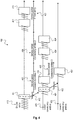
- Fig. 4 is a schematic diagram illustrating time synchronization 400 for a multi-layered wireless communication network according to an exemplary aspect of the present disclosure.
- the time synchronization 400 is structured for a hierarchical multi-layered network, e.g. a multi-layered wireless communication network 200, 300 as described above with respect to Figures 2 and 3 .
- a first hierarchy level is formed by an allocate entity 401, e.g. a control entity 800 as described below with respect to Fig. 8 , which may be implemented in a GW, e.g. a GW 101, 201, 301 as described above with respect to Figures 1 to 3 .
- a second hierarchy level is formed by level I connectivity entities 420, e.g. second level serving devices (e.g. RE)s or central serving device entity (e.g. AP)s as described above with respect to Figs. 2 and 3 .
- a third hierarchy level is formed by level II connectivity entities 430, e.g. REs or central serving device entity (e.g. AP)s as described above with respect to Figs. 2 and 3 .
- the time synchronization and multi-level resource allocation 400 shown in Fig. 4 provides an IEEE 802.11 standards compliant multi-level over the air timing synchronization coordination between the serving devices entities and the devices that are connected either directly (over the air) or indirectly (can receive the sync info) and/or to other serving devices entities or via one or more RE.
- the example over the air time synchronization scheme 400 in Fig. 4 has multi-level over-the-air timing synchronization and resource allocation (service period for example) that used the 802.11 EDCF air access methodology (e.g. as described above with respect to Figure 2 and 3 ).
- the expand entity 410 conducts timing synchronization and allocates service period 425, 426 RU allocation and transmission format for the next level of the network (devices 420 that are connected directly to the offer entity 410) using dedicated SYNC signaling 411 transmitted at the operating frequency. Every serving devices entities can also conduct timing synchronization and allocate service period RU allocation and transmission format for their next level network.
- the middle section 520 of diagram 500 depicts color coding resource allocation scheme in 802.11ax AP/STA networks. Based on color coding resource allocation scheme, different thresholds for detecting serving devices can be applied. In the right section a first power threshold can be applied to differentiate between serving devices of same color code and serving devices. In the left section a second power threshold can be applied to differentiate between other serving devices of other color code (CC) and other serving devices. The same color code indicates the own serving devices (basic service set) while another color code indicates another serving devices unequal to the own serving devices.
- CC color code
- IEEE 802.11ax specifies 6 bits for serving devices color coding (i.e. 63 options) allocation signaling. Each serving devices can be assigned with a different color code. STA, based on detected color code, may determine whether packet is coming from intra-serving devices or inter-serving devices, use different threshold color code values for these 2 cases to improve system performance by (1) minimizing hidden node for Intra-serving devices traffic, and (2) continue working in the presence of low received signal coming from Inter-serving devices.
- the middle section 520 shows how using two threshold values, enables including all wanted (same color code) devices while excluding unwanted inter-serving devices.
- 802.11ax defines only two states depending if color code is identical or not.
- the right section 530 of diagram 500 illustrates an extension of the 11ax defined color codes allocation scheme to support hierarchical color scheme allocation scheme that reflects a multi-layered network topology, e.g. as described above with respect to Figures 1 to 3 .
- the color coding allocation scheme indication is split to 2 sections 531, 532.
- the first section 531 reflects the higher layer that the second level serving devices is connected to the centralized entity.
- the second section 532 assigns a unique color to each of the serving devices/ Group or serving devices.
- the 6 bits of color code can be divided into 2 groups of 3 bits each, where the MSB bits define the first hierarchy and the LSB bits define the second hierarchy.
- the central entity e.g. control entity 800 described below with respect to Fig.
- Resources allocation shown in Figures 6a and 6b may be applied to a system that consists of multi layers serving device entities (e.g. central serving device entity (e.g AP), RE, etc.), e.g. a multi-layered wireless communication network 200, 300 as described above with respect to Figures 2 and 3 , that can be either co-located with a gateway or in a remote server, and client devices that are connected in a synchronized way, either directly to the connectivity entities or via one or more second level serving device. All connectivity entities may be connected between themselves in a synchronized mode as well.
- the L2 resource allocation, air-access parameters and routing and timing may be conducted by temporary workaround on the 802.11ax signaling.
- Figures 6a and 6b illustrate a connectivity entity single-hop(two level) L2 resources allocation and routing and timing synchronization methodology at 4*20 MHz operation scenario.
- a central serving device entity e.g. AP
- RE#1, 2 are allocated with 20 MHz each, while RE#3 is allocated with 40 MHz.
- the central entity serving device (e.g. AP) resources allocation signaling can be done using distributed L2 resources allocation and/or centralized L2 resources allocation and timing synchronization methods. This resources allocation signaling can be performed by the control resources allocation entity 800 described below with respect to Fig. 8 .
- RE based distributed L2 resources allocation and timing method the central entity serving device allocates a pool of resources to a specific second level serving devices and then the second level serving devices (e.g. RE) decides how to allocate resources to his associated STAs and signals it to them using a per second level serving devices TF.
- the central entity serving device allocates resources to a specific end point device (that is associated with a specific second level serving devices), then the second level serving devices signals these allocated resources using a per second level serving devices TF.
- Central serving device entity e.g. AP
- L2 resources allocation and timing signaling (e.g. implemented by the control entity 800 described below with respect to Fig. 8 ) using modified 11ax trigger frame element can be performed in a distributed manner or in a centralized manner.
- the central serving device entity e.g. AP
- the second level serving devices e.g. RE
- the central serving device entity e.g. RE
- the AP signals the allocated pool of resources using a specific AID per STA (this AID assign to STA at first association.
- the second level serving devices e.g. RE
- RE the second level serving devices that decodes this allocation can know its L2 resources allocation and timing that are relevant for its associated STAs and then can transmit this info in its TF.
- Another alternative method is using a proprietary TF resources allocation format, e.g. as described below with respect to Fig. 7 showing an example of a proprietary resources allocation signaling format solution that reuses the trigger frame defined in 11ax.
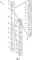
- Fig. 7 is a schematic diagram illustrating an exemplary resources allocation signaling format 700 according to an exemplary aspect of the present disclosure.
- Fig. 7 shows an example of a proprietary resources allocation signaling format solution that reuses the trigger frame structure defined in 11ax.
- the resources allocation signaling format 700 includes the following exemplary data fields: frame control 710, duration 711, RA 712, TA 713, common info 714, per user info 715, others 716, per user info 717, padding 718 and FCS 719.
- the common info field 714 may include the following proprietary exemplary extension data fields: length 720, cascade indication 721, CS required 722, HE-Sig-A Info 723, CP and LTF type 724, trigger type (IRE) 725, second level serving devices info 726 and trigger dependent info 727.
- the per user info field 717 may include the following proprietary exemplary extension data fields: user identifier 730, second level serving devices index 731, UL/DL 732, RU allocation 733, coding type 734, MCS 735, DCM 736, SS allocation 737 and trigger dependent per user info 738.
- second level serving devices fields denote intelligent range extender and may include information regarding the range extenders described above with respect to Figures 1 to 6 .
- Fig. 8 is a block diagram of an exemplary control entity 800 for controlling a communication network according to an exemplary aspect of the present disclosure.
- the control entity 800 includes a traffic monitor 801 and a controller 802.
- the traffic monitor 801 may be a software or hardware unit that is configured to monitor data traffic as described below.
- the controller 802 may also be a software or hardware unit.
- the communication network may be comprised of a plurality of communication clients which are connectable via a plurality of connectivity entities, e.g. a communication network 100, 200, 300 as described above with respect to Figures 1 to 3 .
- the traffic monitor 801 is configured to monitor data traffic of at least one transmission queue of each connectivity entity of the plurality of connectivity entities.
- a connectivity entity may comprise an access point, e.g. gateway 101, 201, 301, e.g. as described above with respect to Figures 1 to 3 or a range extender 110, 120, 130, 210, 220 as described above with respect to Figures 1 and 2 or any other connectivity entity, e.g. one of the connectivity entities 310, 320, 330 as described above with respect to Figure 3 .
- a transmission queue may for example comprise one of the transmission queues Q1 to Q12 as described above with respect to Figure 3 .
- Data traffic may comprise in traffic, out traffic and traffic through MAC/PHY, e.g. as described above with respect to Figure 3 .
- a communication client may be any client, station or mobile device, e.g. any of the clients 111, 112, 113, 121, 122, 131, 132 described above with respect to Figure 1 or any of the clients 202, 203, 204, 205, 211, 221, 222, 223 described above with respect to Figure 2 or any of the clients 305, 313, 323, 333 described above with respect to Figure 3 .
- the controller 802 is configured to allocate resources to each connectivity entity of the plurality of connectivity entities based on the monitored data traffic and according to quality of service requirements of each of the communication clients.
- the control entity 800 may also be referred to as allocate entity, e.g. according to the allocate entity 410 described above with respect to Fig. 4 or may be referred to as communication manager, e.g. as described above with respect to Fig. 1 .
- the communication network comprises a self-organized multi-layered wireless LAN network, e.g. as described above with respect to Figures 1 to 3 .
- Each connectivity entity may comprise at least one communication channel, e.g. a communication channel 208, 209, 218, 219, 228, 229 as described above with respect to Figure 2 , configured to transmit the data traffic of the at least one transmission queue.
- the at least one transmission queue may comprise a Layer 2 transmission queue, e.g. as described above with respect to Figures 2 to 3 .
- the controller 802 may be configured to form a routing topology to connect the plurality of communication clients via the plurality of connectivity entities, e.g. a routing topology as described above with respect to Figures 2 to 3 .
- the controller 802 may be configured to adjust routing and channel assignment of the plurality of connectivity entities based on the monitored data traffic and the quality of service requirements of each of the communication clients, e.g. as described above with respect to Figures 2 to 3 .
- the controller 802 may allocate the resources based on Layer 2 load balancing air-access.
- the controller 802 may allocate the resources based on an air-access based traffic priorities fairness function, e.g. as described above with respect to Figures 2 to 3 .
- Priorities fairness function means fairness between priorities segments.
- the quality of service requirements of each of the communication clients may be based on end-to-end quality of service requirements.
- the controller 802 may allocate the resources based on Layer 2 load balancing and Layer 2 re-routing between service and backhaul
- the plurality of connectivity entities may comprise at least one of a range extender and an access point, e.g. a range extender or intelligent range extender 110, 120, 130, 210, 220 as described above with respect to Figures 1 to 2 or an access point or gateway 101, 201, 301 as described above with respect to Figures 1 to 3 .
- the plurality of communication clients may be connectable either directly or via one or more of the range extenders to the plurality of connectivity entities.
- the controller 802 may allocate the resources based on a total air-time required by each communication client passing through a specific number of the range extenders.
- the controller 802 may determine an air time required by a communication client passing through a specific range extender based on a function of a payload, a quality of service, a path loss, a signal-to-interface ratio, a channel load, a radio frequency bandwidth and a number of antennas of the specific range extender, e.g. as described above with respect to Figures 2 to 3 .
- At least one of the connectivity entities may be collocated with a gateway or located in a remote server.
- the controller 802 may control timing synchronization of the plurality of connectivity entities, e.g. as described above with respect to Figure 4 .
- the plurality of connectivity entities may be hierarchically arranged, e.g. as shown above in Figures 1 to 3 .
- the controller 802 may be configured to time synchronize connectivity entities of a first hierarchy level.
- the connectivity entities of the first hierarchy level may be configured to time synchronize connectivity entities of a second hierarchy level.
- the control entity may be implemented in a gateway, e.g. a gateway 101, 201, 301 as described above with respect to Figures 1 to 3 .
- the communication network may comprise a self-organized wireless LAN network comprising multiple layers of range extenders associated with specific communication clients, e.g. as described above with respect to Figures 1 to 3 .
- the controller 802 may signal Layer 2 resources allocation and timing to the communication clients based on distributed L2 resources allocation and timing or based on centralized L2 resources allocation and timing, e.g. as described above with respect to Figures 2 to 3 .
- the controller 802 may allocate a pool of resources to a specific range extender which determines resources allocation and signals the allocated resources to its associated communication clients by using a trigger frame, e.g. as described above with respect to Figures 2 to 3 .
- the controller 802 may allocate resources to a specific communication client that is associated with a specific range extender which signals the allocated resources to the specific communication client by using a trigger frame, e.g. as described above with respect to Figures 2 to 3 .
- the trigger frame may indicate L2 resources allocation, time synchronization and transmission format signaling, e.g. as described above with respect to Figures 2 to 3 .
- the transmission format signaling may comprise at least one of the following parameters: transmission format parameters, specific radio unit allocation per communication client and/or range extender and transmit power, e.g. as described above with respect to Figure 7 .
- the data traffic may be based on hierarchical color coding reflecting a multi-layered network topology, e.g. as described above with respect to Figure 5 , in particular with the right diagram 530 of Fig. 5 .
- the hierarchical color coding may comprise a first section, e.g. a first section 532 as depicted in Fig. 5 , indicating a central entity where the range extenders are connected to.
- the hierarchical color coding may comprise a second section, e.g. a second section 531 as depicted in Fig. 5 , assigning a unique color code to each of the range extenders or to each group of range extenders.
- a method for controlling a communication network comprised of a plurality of communication clients which are connectable via a plurality of connectivity entities includes: monitoring data traffic of at least one transmission queue of each connectivity entity of the plurality of connectivity entities; and allocating resources to each connectivity entity of the plurality of connectivity entities based on the monitored data traffic and according to quality of service requirements of each of the communication clients.
- the communication network may comprise a self-organized multi-layered wireless LAN network.
- the method may include forming a routing topology to connect the plurality of communication clients via the plurality of connectivity entities.
- the plurality of connectivity entities may comprise at least one of a range extender and an access point device.
- the method may further include: controlling timing synchronization of the plurality of connectivity entities.
- the communication network may comprise a self-organized wireless LAN network comprising multiple layers of range extenders associated with specific communication clients.
- the method may further include: signaling Layer 2 resources allocation and timing to the communication clients based on distributed L2 resources allocation and timing or based on centralized L2 resources allocation and timing.
- the distributed L2 resources allocation and timing may comprise: allocating a pool of resources to a specific range extender; determining resources allocation by the specific range extender; and signaling the allocated resources by the specific range extender to its associated communication clients by using a trigger frame.
- the centralized L2 resources allocation and timing may comprise: allocating resources to a specific communication client that is associated with a specific range extender; signaling, by the specific range extender, the allocated resources to the specific communication client by using a trigger frame.
- the trigger frame may indicate L2 resources allocation, time synchronization and transmission format signaling.
- the data traffic may be based on hierarchical color coding reflecting a multi-layered network topology, e.g. as described above with respect to Figures 2 and 3 .
- aspects of the disclosure as described above introduce a standards-compliant solution for using IEEE 802.11ax synchronized mode of operation, for supporting WLAN 802.11ax based SON (self-organized Networks) network, in particular synchronized network that implements multiple layers Range Extenders (RE) deployments.
- IEEE 802.11ax synchronized mode of operation for supporting WLAN 802.11ax based SON (self-organized Networks) network, in particular synchronized network that implements multiple layers Range Extenders (RE) deployments.
- SON self-organized Networks
- DSP Digital Signal Processors
- ASIC application specific integrated circuit
- Embodiments described in this disclosure can be implemented in digital electronic circuitry, or in computer hardware, firmware, software, or in combinations thereof, e.g. in available hardware of mobile devices or in new hardware dedicated for processing the methods described herein.
- the present disclosure also supports a computer program product including computer executable code or computer executable instructions that, when executed, causes at least one computer to execute the performing and computing blocks described herein, in particular the methods 200, 300, 500 described above with respect to Figs. 2 , 3 and 5 and the computing blocks described above with respect to Figure 4 .
- a computer program product may include a non-transient readable storage medium storing program code thereon for use by a processor, the program code comprising instructions for performing the methods or the computing blocks as described above.
- Example 1 is a serving entities control entity for controlling a communication network comprised of a plurality of communication clients which are connectable via a plurality of serving entities, the serving entities control entity comprising: a traffic monitor, configured to monitor data traffic of at least one transmission queue of each serving entity of the plurality of serving entities; and a controller, configured to allocate resources to each serving entity of the plurality of serving entities based on the monitored data traffic and according to quality of service requirements of each of the communication clients.
- a traffic monitor configured to monitor data traffic of at least one transmission queue of each serving entity of the plurality of serving entities
- a controller configured to allocate resources to each serving entity of the plurality of serving entities based on the monitored data traffic and according to quality of service requirements of each of the communication clients.
- Example 2 the subject matter of Example 1 can optionally include that the communication network comprises a self-organized multi-layered wireless LAN network.
- Example 3 the subject matter of any one of Examples 1-2 can optionally include that each serving entity comprises at least one communication channel configured to transmit the data traffic of the at least one transmission queue.
- Example 4 the subject matter of any one of Examples 1-3 can optionally include that the at least one transmission queue comprises a Layer 2 transmission queue.
- Example 5 the subject matter of any one of Examples 1-4 can optionally include that the controller is configured to form a routing topology to connect the plurality of communication clients via the plurality of serving entities.
- Example 6 the subject matter of any one of Examples 1-5 can optionally include that the controller is configured to adjust routing and channel assignment of the plurality of serving entities based on the monitored data traffic and the quality of service requirements of each of the communication clients.
- Example 7 the subject matter of any one of Examples 1-6 can optionally include that the controller is configured to allocate the resources based on Layer 2 load balancing air-access.
- Example 8 the subject matter of any one of Examples 1-7 can optionally include that the controller is configured to allocate the resources based on an air-access based traffic priorities fairness function.
- Priorities fairness function means fairness between priorities segments.
- Example 9 the subject matter of any one of Examples 1-8 can optionally include that the quality of service requirements of each of the communication clients are based on end-to-end quality of service requirements.
- Example 10 the subject matter of any one of Examples 1-9 can optionally include that the controller is configured to allocate the resources based on Layer 2 load balancing and Layer 2 re-routing between service (i.e. traffic between serving entities and connectivity entities) and backhaul traffic (i.e. traffic between serving entities and other serving entities) requirements.
- Backhaul traffic refers to traffic between serving entities and other serving entities; and traffic between serving entities and connectivity entities.
- Example 11 the subject matter of any one of Examples 1-10 can optionally include that the plurality of serving entities comprises at least one of a range extender and an access point device.
- Example 12 the subject matter of Example 11 can optionally include that the plurality of communication clients are connectable either directly or via one or more of the range extenders to the plurality of serving entities.
- Example 13 the subject matter of any one of Examples 11-12 can optionally include that the controller is configured to allocate the resources based on a total air-time required by each communication client passing through a specific number of the range extenders.
- Example 14 the subject matter of Example 13 can optionally include that the controller is configured to determine an air time required by a communication client passing through a specific range extender based on a function of a payload, a quality of service, a path loss, a signal-to-interface ratio, a channel load, a radio frequency bandwidth and a number of antennas of the specific range extender.
- Example 15 the subject matter of any one of Examples 1-14 can optionally include that at least one of the serving entities is collocated with a gateway or located in a remote server.
- Example 16 the subject matter of any one of Examples 1-15 can optionally include that the controller is configured to control timing synchronization of the plurality of serving entities.
- Example 17 the subject matter of any one of Examples 1-16 can optionally include that the plurality of serving entities are hierarchically arranged.
- Example 18 the subject matter of Example 17 can optionally include that the controller is configured to time synchronize serving entities of a first hierarchy level; and that the serving entities of the first hierarchy level are configured to time synchronize serving entities of a second hierarchy level.
- Example 19 the subject matter of any one of Examples 1-18 can optionally include that the serving entities control entity is implemented in a gateway.
- Example 20 the subject matter of any one of Examples 1-19 can optionally include that the communication network comprises a self-organized wireless LAN network comprising multiple layers of range extenders associated with specific communication clients.
- Example 21 the subject matter of Example 20 can optionally include that the controller is configured to signal Layer 2 resources allocation and timing to the communication clients based on distributed L2 resources allocation and timing or based on centralized L2 resources allocation and timing.
- Example 22 the subject matter of Example 21 can optionally include that for the distributed L2 resources allocation and timing the controller allocates a pool of resources to a specific range extender which determines resources allocation and signals the allocated resources to its associated communication clients by using a trigger frame.
- Example 23 the subject matter of Example 21 can optionally include that for the centralized L2 resources allocation and timing the controller allocates resources to a specific communication client that is associated with a specific range extender which signals the allocated resources to the specific communication client by using a trigger frame.
- Example 24 the subject matter of any one of Examples 22-23 can optionally include that the trigger frame indicates L2 resources allocation, time synchronization and transmission format signaling.
- Example 25 the subject matter of Example 24 can optionally include that the transmission format signaling comprises at least one of the following parameters: transmission format parameters, specific radio unit allocation per communication client and/or range extender and transmit power.
- Example 26 the subject matter of any one of Examples 20-25 can optionally include that the data traffic is based on hierarchical color coding reflecting a multi-layered network topology.
- Example 27 the subject matter of Example 26 can optionally include that the hierarchical color coding comprises a first section indicating a central entity where the range extenders are connected to.
- Example 28 the subject matter of Example 27 can optionally include that the hierarchical color coding comprises a second section assigning a unique color code to each of the range extenders or to each group of range extenders.
- Example 29 is a method for controlling a communication network comprised of a plurality of communication clients which are connectable via a plurality of serving entities, the method comprising: monitoring data traffic of at least one transmission queue of each serving entity of the plurality of serving entities; and allocating resources to each serving entity of the plurality of serving entities based on the monitored data traffic and according to quality of service requirements of each of the communication clients.
- Example 30 the subject matter of Example 29 can optionally include that the communication network comprises a self-organized multi-layered wireless LAN network.
- Example 31 the subject matter of any one of Examples 29-30 can optionally include: forming a routing topology to connect the plurality of communication clients via the plurality of serving entities.
- Example 32 the subject matter of any one of Examples 29-31 can optionally include that the plurality of serving entities comprises at least one of a range extender and an access point device.
- Example 33 the subject matter of any one of Examples 29-32 can optionally include: controlling timing synchronization of the plurality of serving entities.
- Example 34 the subject matter of any one of Examples 29-33 can optionally include that the communication network comprises a self-organized wireless LAN network comprising multiple layers of range extenders associated with specific communication clients.
- Example 35 the subject matter of Example 34 can optionally include: signaling Layer 2 resources allocation and timing to the communication clients based on distributed L2 resources allocation and timing or based on centralized L2 resources allocation and timing.
- Example 36 the subject matter of Example 35 can optionally include that the distributed L2 resources allocation and timing comprises: allocating a pool of resources to a specific range extender; determining resources allocation by the specific range extender; and signaling the allocated resources by the specific range extender to its associated communication clients by using a trigger frame.
- Example 37 the subject matter of Example 35 can optionally include that the centralized L2 resources allocation and timing comprises: allocating resources to a specific communication client that is associated with a specific range extender; signaling, by the specific range extender, the allocated resources to the specific communication client by using a trigger frame.
- Example 38 the subject matter of any one of Examples 36-37 can optionally include that the trigger frame indicates L2 resources allocation, time synchronization and transmission format signaling.
- Example 39 the subject matter of any one of Examples 34-38 can optionally include that the data traffic is based on hierarchical color coding reflecting a multi-layered network topology.
- Example 41 the subject matter of Example 40 can optionally include that the communication network comprises a self-organized wireless LAN network comprising multiple layers of range extenders associated with specific communication clients.
- Example 42 the subject matter of any one of Examples 40-41 can optionally include that the controller is configured to signal Layer 2 resources allocation and timing to the communication clients based on distributed L2 resources allocation and timing or based on centralized L2 resources allocation and timing.
- Example 43 the subject matter of Example 42 can optionally include that for the distributed L2 resources allocation and timing the controller allocates a pool of resources to a specific range extender which determines resources allocation and signals the allocated resources to its associated communication clients by using a trigger frame.
- Example 44 the subject matter of Example 42 can optionally include that for the centralized L2 resources allocation and timing the controller allocates resources to a specific communication client that is associated with a specific range extender which signals the allocated resources to the specific communication client by using a trigger frame.
- Example 45 the subject matter of any one of Examples 43-44 can optionally include that the trigger frame indicates L2 resources allocation, time synchronization and transmission format signaling.
- Example 46 the subject matter of any one of Examples 40-45 can optionally include that the data traffic is based on hierarchical color coding reflecting a multi-layered network topology.
- Example 47 the subject matter of Example 46 can optionally include that the hierarchical color coding comprises a first section indicating a central entity where the range extenders are connected to.
- Example 48 the subject matter of Example 46 can optionally include that the hierarchical color coding comprises a second section assigning a unique color code to each of the range extenders or to each group of range extenders.
- Example 49 is a device for controlling a communication network comprised of a plurality of communication clients which are connectable via a plurality of serving entities, the method comprising: means for monitoring data traffic of at least one transmission queue of each serving entity of the plurality of serving entities; and means for allocating resources to each serving entity of the plurality of serving entities based on the monitored data traffic and according to quality of service requirements of each of the communication clients.
- Example 50 the subject matter of Example 49 can optionally include that the communication network comprises a self-organized multi-layered wireless LAN network.
- Example 51 is a communication system, comprising: a plurality of serving entities; and a plurality of communication clients which are connectable via the plurality of serving entities; and a serving entities control entity, wherein the serving entities control entity is configured to monitor data traffic of at least one transmission queue of each serving entity of the plurality of serving entities and to allocate resources to each serving entity of the plurality of serving entities based on the monitored data traffic and according to quality of service requirements of each of the communication clients.
- Example 52 the subject matter of Example 51 can optionally include that the plurality of serving entities and the plurality of communication clients are arranged in a self-organized multi-layered wireless LAN network.
- Example 53 is a computer readable non-transitory medium on which computer instructions are stored which when executed by a computer cause the computer to perform the method of any one of Examples 29 to 39.
Landscapes
- Engineering & Computer Science (AREA)
- Computer Networks & Wireless Communication (AREA)
- Signal Processing (AREA)
- Quality & Reliability (AREA)
- Mobile Radio Communication Systems (AREA)
Priority Applications (3)
| Application Number | Priority Date | Filing Date | Title |
|---|---|---|---|
| EP17194170.1A EP3462794A1 (fr) | 2017-09-29 | 2017-09-29 | Techniques permettant de commander des réseaux de communication |
| PCT/US2018/047924 WO2019067121A1 (fr) | 2017-09-29 | 2018-08-24 | Techniques de commande de réseaux de communication |
| US16/650,572 US20200229193A1 (en) | 2017-09-29 | 2018-08-24 | Techniques for controlling communication networks |
Applications Claiming Priority (1)
| Application Number | Priority Date | Filing Date | Title |
|---|---|---|---|
| EP17194170.1A EP3462794A1 (fr) | 2017-09-29 | 2017-09-29 | Techniques permettant de commander des réseaux de communication |
Publications (1)
| Publication Number | Publication Date |
|---|---|
| EP3462794A1 true EP3462794A1 (fr) | 2019-04-03 |
Family
ID=60051340
Family Applications (1)
| Application Number | Title | Priority Date | Filing Date |
|---|---|---|---|
| EP17194170.1A Withdrawn EP3462794A1 (fr) | 2017-09-29 | 2017-09-29 | Techniques permettant de commander des réseaux de communication |
Country Status (3)
| Country | Link |
|---|---|
| US (1) | US20200229193A1 (fr) |
| EP (1) | EP3462794A1 (fr) |
| WO (1) | WO2019067121A1 (fr) |
Cited By (3)
| Publication number | Priority date | Publication date | Assignee | Title |
|---|---|---|---|---|
| WO2021027783A1 (fr) * | 2019-08-14 | 2021-02-18 | 华为技术有限公司 | Procédé, appareil, dispositif et système permettant d'attribuer des ressources de radiofréquence, et support de stockage |
| US11132109B2 (en) | 2019-05-08 | 2021-09-28 | EXFO Solutions SAS | Timeline visualization and investigation systems and methods for time lasting events |
| US12150156B2 (en) | 2019-08-14 | 2024-11-19 | Huawei Technologies Co., Ltd. | Radio frequency resource allocation method, apparatus, device and system, and storage medium |
Families Citing this family (3)
| Publication number | Priority date | Publication date | Assignee | Title |
|---|---|---|---|---|
| BR112021016771A2 (pt) * | 2019-03-08 | 2021-11-30 | Assia Spe Llc | Otimizaçâo restrita de enlace sem fio em redes com objetivos concorrentes |
| US11690022B2 (en) * | 2020-03-24 | 2023-06-27 | Qualcomm Incorporated | Managing transmit power control |
| CN117676697A (zh) * | 2023-11-14 | 2024-03-08 | 北京邮电大学 | 一种物联网设备的数据传输方法和系统 |
Citations (3)
| Publication number | Priority date | Publication date | Assignee | Title |
|---|---|---|---|---|
| US20160255538A1 (en) * | 2014-12-30 | 2016-09-01 | Meru Networks | Load balancing for a cloud-based wi-fi controller based on local conditions |
| US20170222905A1 (en) * | 2016-02-01 | 2017-08-03 | Huawei Technologies Co., Ltd. | Method and system for communication network configuration using virtual link monitoring |
| WO2017146793A1 (fr) * | 2016-02-25 | 2017-08-31 | Arizona Board Of Regents On Behalf Of Arizona State University | Systèmes et procédés destinés à une architecture de liaison terrestre à base de sdn en couches pour petites cellules |
Family Cites Families (5)
| Publication number | Priority date | Publication date | Assignee | Title |
|---|---|---|---|---|
| EP1864517A4 (fr) * | 2005-03-14 | 2013-08-21 | Atmel Corp | Procede et appareil pour le fonctionnement d'un reseau personnel utilisant un protocole de recouvrement qui ameliore la coexistence avec un reseau local sans fil |
| US7440436B2 (en) * | 2005-05-13 | 2008-10-21 | Natural Lighting Systems, Inc. | Self-organizing multi-channel mesh network |
| US9100832B2 (en) * | 2009-10-30 | 2015-08-04 | Airhop Communications, Inc. | Method and apparatus for self organized network |
| TW201309053A (zh) * | 2011-08-03 | 2013-02-16 | Acer Inc | 動態調整通訊協定之視窗大小以增加無線網路系統內資料流通量之方法 |
| US9792129B2 (en) * | 2014-02-28 | 2017-10-17 | Tyco Fire & Security Gmbh | Network range extender with multi-RF radio support for plurality of network interfaces |
-
2017
- 2017-09-29 EP EP17194170.1A patent/EP3462794A1/fr not_active Withdrawn
-
2018
- 2018-08-24 WO PCT/US2018/047924 patent/WO2019067121A1/fr not_active Ceased
- 2018-08-24 US US16/650,572 patent/US20200229193A1/en not_active Abandoned
Patent Citations (3)
| Publication number | Priority date | Publication date | Assignee | Title |
|---|---|---|---|---|
| US20160255538A1 (en) * | 2014-12-30 | 2016-09-01 | Meru Networks | Load balancing for a cloud-based wi-fi controller based on local conditions |
| US20170222905A1 (en) * | 2016-02-01 | 2017-08-03 | Huawei Technologies Co., Ltd. | Method and system for communication network configuration using virtual link monitoring |
| WO2017146793A1 (fr) * | 2016-02-25 | 2017-08-31 | Arizona Board Of Regents On Behalf Of Arizona State University | Systèmes et procédés destinés à une architecture de liaison terrestre à base de sdn en couches pour petites cellules |
Cited By (4)
| Publication number | Priority date | Publication date | Assignee | Title |
|---|---|---|---|---|
| US11132109B2 (en) | 2019-05-08 | 2021-09-28 | EXFO Solutions SAS | Timeline visualization and investigation systems and methods for time lasting events |
| WO2021027783A1 (fr) * | 2019-08-14 | 2021-02-18 | 华为技术有限公司 | Procédé, appareil, dispositif et système permettant d'attribuer des ressources de radiofréquence, et support de stockage |
| US11576187B2 (en) | 2019-08-14 | 2023-02-07 | Huawei Technologies Co., Ltd. | Radio frequency resource allocation method, apparatus, device and system, and storage medium |
| US12150156B2 (en) | 2019-08-14 | 2024-11-19 | Huawei Technologies Co., Ltd. | Radio frequency resource allocation method, apparatus, device and system, and storage medium |
Also Published As
| Publication number | Publication date |
|---|---|
| WO2019067121A1 (fr) | 2019-04-04 |
| US20200229193A1 (en) | 2020-07-16 |
Similar Documents
| Publication | Publication Date | Title |
|---|---|---|
| US20200229193A1 (en) | Techniques for controlling communication networks | |
| CN107113795B (zh) | 用于非授权频谱中联合协调和共存的方法和系统 | |
| US10548071B2 (en) | System and method for communicating traffic over licensed or un-licensed spectrums based on quality of service (QoS) constraints of the traffic | |
| CN110649998B (zh) | 用于在授权频谱和非授权频谱上动态分配资源的系统与方法 | |
| CN111096031B (zh) | 用于资源隙配置并将用户设备分配到资源隙以控制来自用户设备的信道访问的方法和装置 | |
| KR101891746B1 (ko) | 무선 통신 시스템 및 무선 통신 방법 | |
| CA2600962A1 (fr) | Gestion de qualite de service dans des reseaux mailles sans fil | |
| KR20170094407A (ko) | 시간-영역 프레임 구조의 동적 최적화를 위한 방법 및 시스템 | |
| US9131472B2 (en) | Systems and methods to provision quality of service sensitive devices in wireless local area networks | |
| CN108141851A (zh) | 选择非授权无线通信的信道的方法和系统 | |
| JP6474903B2 (ja) | 無線通信システムおよび無線通信方法 | |
| US20160302206A1 (en) | Method and Apparatus for Communication Processing in Wireless Network | |
| KR20260002730A (ko) | 초고 신뢰성을 위한 조정된 매체 액세스를 위한 기법들 | |
| WO2014089874A1 (fr) | Systèmes et procédés pour obtenir une équité dans les réseaux locaux sans fil pour le déchargement cellulaire | |
| US12501428B2 (en) | Method and apparatus for traffic urgency indication | |
| US9967896B2 (en) | Method and communication node of scheduling radio resources | |
| KR20180129063A (ko) | 무선 통신 시스템에서 서비스의 품질 보장 방법 및 장치 | |
| US10292137B1 (en) | Reducing latency in an unlicensed frequency spectrum | |
| US10813111B1 (en) | Scheduling low-priority transmissions | |
| US20260032515A1 (en) | Link management to improve throughput and operation | |
| US20260040148A1 (en) | Traffic estimation and wireless actions based on wireless traffic ingress rates | |
| US11523321B1 (en) | Method and system for cell prioritization | |
| WO2025244661A1 (fr) | Réutilisation spatiale coordonnée avec partage de support ouvert | |
| Choi et al. | Scalable and energy efficient WiFi management | |
| CN113938956A (zh) | 资源分配方法、装置及计算机可读存储介质 |
Legal Events
| Date | Code | Title | Description |
|---|---|---|---|
| PUAI | Public reference made under article 153(3) epc to a published international application that has entered the european phase |
Free format text: ORIGINAL CODE: 0009012 |
|
| STAA | Information on the status of an ep patent application or granted ep patent |
Free format text: STATUS: REQUEST FOR EXAMINATION WAS MADE |
|
| 17P | Request for examination filed |
Effective date: 20170929 |
|
| AK | Designated contracting states |
Kind code of ref document: A1 Designated state(s): AL AT BE BG CH CY CZ DE DK EE ES FI FR GB GR HR HU IE IS IT LI LT LU LV MC MK MT NL NO PL PT RO RS SE SI SK SM TR |
|
| AX | Request for extension of the european patent |
Extension state: BA ME |
|
| STAA | Information on the status of an ep patent application or granted ep patent |
Free format text: STATUS: EXAMINATION IS IN PROGRESS |
|
| 17Q | First examination report despatched |
Effective date: 20200303 |
|
| RAP1 | Party data changed (applicant data changed or rights of an application transferred) |
Owner name: APPLE INC. |
|
| STAA | Information on the status of an ep patent application or granted ep patent |
Free format text: STATUS: THE APPLICATION IS DEEMED TO BE WITHDRAWN |
|
| 18D | Application deemed to be withdrawn |
Effective date: 20210501 |