EP3462855B1 - Système de régulation et/ou de commande, machine agricole comprenant un tel système et procédé permettant de faire fonctionner une machine agricole - Google Patents
Système de régulation et/ou de commande, machine agricole comprenant un tel système et procédé permettant de faire fonctionner une machine agricole Download PDFInfo
- Publication number
- EP3462855B1 EP3462855B1 EP17720807.1A EP17720807A EP3462855B1 EP 3462855 B1 EP3462855 B1 EP 3462855B1 EP 17720807 A EP17720807 A EP 17720807A EP 3462855 B1 EP3462855 B1 EP 3462855B1
- Authority
- EP
- European Patent Office
- Prior art keywords
- distributor linkage
- sensor device
- sensor
- inclination
- machine
- Prior art date
- Legal status (The legal status is an assumption and is not a legal conclusion. Google has not performed a legal analysis and makes no representation as to the accuracy of the status listed.)
- Active
Links
Images



Classifications
-
- A—HUMAN NECESSITIES
- A01—AGRICULTURE; FORESTRY; ANIMAL HUSBANDRY; HUNTING; TRAPPING; FISHING
- A01M—CATCHING, TRAPPING OR SCARING OF ANIMALS; APPARATUS FOR THE DESTRUCTION OF NOXIOUS ANIMALS OR NOXIOUS PLANTS
- A01M7/00—Special adaptations or arrangements of liquid-spraying apparatus for purposes covered by this subclass
- A01M7/005—Special arrangements or adaptations of the spraying or distributing parts, e.g. adaptations or mounting of the spray booms, mounting of the nozzles, protection shields
- A01M7/0053—Mounting of the spraybooms
- A01M7/0057—Mounting of the spraybooms with active regulation of the boom position
Definitions
- the invention relates to a regulation and/or control system for an agricultural machine with a distributor linkage for spreading material such as fertilisers, plant protection products or seeds.
- the distributor linkage can be pivoted about at least one axis of rotation running in the direction of travel.
- the regulation and/or control system has at least one first sensor device for determining the inclination of the distributor linkage and a data processing device for processing the sensor signals from the first sensor device.
- Such a system is, for example, from WO 2015 040 133 A1 known.
- the disadvantage of the known system is that the inclination sensors supply faulty signals when cornering. proposes to the solution WO 2015 040 133 A1 proposes to measure the rate of rotation around the axis of rotation running in the direction of travel in addition to the inclination of the linkage. The angle of inclination of the linkage is calculated from the measured rate of rotation and, together with the measured angle of inclination, an error-corrected rotational position of the linkage is determined. Only rolling movements of the carrier vehicle around the axis of rotation of the linkage running in the direction of travel are recorded.
- the object of the invention is to improve the regulation and/or control system of the type mentioned at the outset with a view to measuring accuracy in different driving situations.
- the invention is also based on the object of specifying an agricultural machine with such a system and a method for operating an agricultural machine.
- the object is achieved according to the invention by the subject matter of claim 1 .
- the object is achieved according to the invention by the subject matter of claim 10 or the subject matter of claim 12.
- the invention is based on the idea of specifying a regulation and/or control system for an agricultural machine that has a distributor linkage for spreading material such as fertilizers, crop protection agents or seed.
- the distributor linkage can be pivoted about at least one axis of rotation running in the direction of travel.
- the system has at least a first sensor device for determining the inclination of the distributor linkage and a data processing device for processing the sensor signals.
- the invention is characterized by a second sensor device for determining the centrifugal force F F and/or the centrifugal acceleration a F which acts on the first sensor device when the machine is cornering.
- the data processing device is designed in such a way that an inclination measurement error of the first sensor device can be corrected on the basis of the sensor signals of the second sensor device.
- the invention has the advantage that the disturbance variable which falsifies the measurement result, namely the centrifugal force F F and/or the centrifugal acceleration a F , is determined directly at the first sensor device. Especially when cornering, this means that measurement errors are eliminated and the measurement accuracy is significantly improved.
- the centrifugal force F F and/or the centrifugal acceleration a F can be determined in various ways.
- the centrifugal force F F is preferably determined directly by measurement by the second sensor device.
- the centrifugal force F F and/or the centrifugal acceleration a F can, for example, also be calculated indirectly on the basis of vehicle parameters, such as the yaw rate about the vertical axis and the driving speed, with the yaw rate preferably being measured by the second sensor device.
- the data processing device is adapted to process the driving speed of the machine.
- the vehicle speed is corrected based on the sensor signals during error correction the second sensor device is taken into account.
- the driving speed is included in the calculation of the centrifugal acceleration.
- the data processing device can be adapted to factor the driving speed, with the factoring being adjustable. This allows possible constant errors in the calculation to be compensated.
- the data processing device can be adapted to process a steering angle of the machine, which is taken into account in the error correction based on the sensor signals of the second sensor device
- the second sensor device can include at least one yaw rate sensor, which is adapted to measure the yaw rate of the distributor linkage and/or the machine about the vertical axis. Based on the measurement of the yaw rate about the vertical axis, the load on the first sensor device can be determined by transverse forces, for example when cornering.
- the vertical axis or vertical axis is the axis about which yaw movements of the distributor linkage and/or the machine take place, the angular velocity of which is measured by the yaw rate sensor.
- Another advantage of detecting the yaw rate about the vertical axis is that the error correction is very precise when cornering continues. In contrast to this, inaccuracies can occur during continuous cornering due to drift effects in the correction by means of the known detection of the rate of rotation about the axis of rotation running in the direction of travel.
- the second sensor device can comprise a plurality of yaw rate sensors, in particular at least two or three yaw rate sensors, whose measuring axes run orthogonally to one another. This improves the measurement in the event that the second sensor device itself is inclined.
- the directions of rotation can be better determined in this way, specifically by determining a resulting rate of rotation based on the measurements about the axes of rotation that are orthogonal to one another.
- the first sensor device can be based on an inclination sensor, in particular an inclination sensor for measuring the inclination of the distributor linkage a reference axis running in the direction of gravitational acceleration (direction of perpendicular).
- This has the advantage that it is possible to regulate to an absolute inclination value in relation to the direction of gravity, ie in the direction of the force of gravity (weight) acting downwards.
- the first sensor device comprises a sensor for determining the rate of rotation of the distributor linkage about the axis of rotation of the distributor linkage running in the direction of travel.
- the sensor for determining the yaw rate can be a yaw rate sensor or an acceleration sensor.
- the sensor for determining the rate of rotation of the distributor linkage can be combined with the inclination sensor. This has the advantage that the target value for the inclination can be specified by the user.
- the machine movements are decoupled from the linkage movements on the basis of the signals from the sensor for determining the rate of rotation of the distributor linkage.
- the data processing device is adapted accordingly.
- At least one third sensor device is provided for determining the distance of the distributor linkage from the ground and/or from the vegetation and/or from obstacles. With the aid of the third sensor device, the inclination of the distributor linkage is set in relation to the ground.
- the data processing device is preferably configured for an automatic mode for adjusting the height and/or inclination of the distributor linkage and for an override mode for adjusting the height and/or inclination of the distributor linkage.
- the override mode can be a manual override mode, for example.
- automatic mode the data processing device adjusts the overall height and/or overall inclination of the distributor linkage.
- the data processing device overrides at least one control parameter of the automatic mode that is active in the override mode.
- the data processing device overrides at least one control parameter of the automatic mode, in particular through a manual input.
- Override means that the automatic mode is active in the override mode or remains active when the automatic mode override mode is switched on.
- a control parameter of the automatic mode e.g. the absolute inclination value in relation to the direction of gravity, is specifically changed in the override mode in order to give the user of the machine the opportunity to intervene in the automatic control, e.g. to avoid collisions.
- the override is preferably a manual override, ie an override that is at least triggered by a manual input by a user.
- Manual override may also include user adjustment of control behavior.
- the automatic mode is the regulation during normal operation of the machine.
- the override when the automatic mode is active ensures that the active decoupling of the movements of the distributor linkage from the movements of the machine, e.g. due to the sensor for determining the rate of rotation of the distributor linkage around the axis of rotation of the distributor linkage running in the direction of travel, is maintained, even if a Intervention, in particular manual intervention, takes place in the automatic control.
- a Intervention in particular manual intervention
- the data processing device is preferably configured for a manual mode with rigid power transmission to the distributor linkage, with a change to a decoupling mode with a decoupled distributor linkage, in particular in the automatic mode and/or in the override mode, a current inclination value of the distributor linkage being adopted as the new desired inclination value.
- the second sensor device for determining the centrifugal force F F and / or the centrifugal acceleration a F which acts on the first Sensor device acts when cornering the machine, is arranged on the machine or on the distributor linkage.
- the method according to the invention for operating an agricultural machine is based on the fact that material, such as fertilizer, crop protection agent or seed, is applied from a storage container through a distributor linkage.
- material such as fertilizer, crop protection agent or seed
- an absolute inclination value of the distributor linkage relative to the direction of gravity is controlled on the basis of sensor signals from at least one first sensor device for determining the inclination of the distributor linkage.
- a measurement error of the first sensor device is corrected on the basis of sensor signals from at least one second sensor device for determining the centrifugal force F F and/or the centrifugal acceleration a F that acts on the first sensor device when the machine is cornering. This improves the measurement accuracy.
- FIG. 1 shows a schematic rear view of an agricultural machine 2, which is designed as a field sprayer.
- the machine can be towed, self-propelled or vehicle-mounted.
- the machine has a distributor linkage 3, which is connected to a storage container 5 for the supply of the material to be spread.
- the material can be crop protection products, seeds or fertilizers.
- the distributor linkage 3 has nozzles which are distributed on the underside of the distributor linkage 3 .
- the nozzles are connected to a pump and the reservoir 5 by a hose system, which is also known per se.
- the distributor linkage 3 is suspended centrally on the frame of the machine and can be pivoted about an axis of rotation pointing in the direction of travel, as indicated by the double arrow. An adjustment of the overall inclination of the distributor linkage 3, ie an adjustment of the unfolded, straight distributor linkage 3, is thus possible.
- the axis of rotation a is at a distance from the center of gravity b of the distributor linkage 3 .
- the centrifugal forces also act on those for tilt control provided inclination sensors or the inclination sensor.
- the regulation and/or control system is adapted accordingly, as described in more detail below.
- the invention and the exemplary embodiments described below relate to a distributor linkage according to FIG 2 with the center of gravity b of the distributor linkage 3 spaced axis of rotation a. It is also conceivable to apply the invention or the exemplary embodiments described below to a distributor linkage 3 in which the axis of rotation a, about which the distributor linkage 3 can be pivoted, runs through the center of gravity b.
- the distributor linkage 3 can have a non-rotatably arranged central part, on which a respective cantilever arm is articulated in a pivotable manner.
- a respective cantilever arm is articulated in a pivotable manner.
- the two pivot arms can each be pivoted about a central axis of the vehicle pointing in the direction of travel.
- the distributor linkage 3 is also adjustable in height.
- the distributor linkage can be attached to a vertically movable lifting frame.
- a parallelogram linkage can be provided to adjust the altitude.
- Hydraulic systems known per se or other adjustment systems can be considered as actuators for the inclination and height adjustment.
- the invention is not limited to a specific mechanism for adjusting the inclination or for adjusting the height of the distributor linkage 3 .
- the agricultural machine 2 has a regulation and/or control system (not shown), which includes a data processing device for processing sensor signals from various sensor devices, which are explained in more detail below.
- the regulation and/or control system has a first sensor device, which is designed to determine the inclination of the distributor linkage 3 .
- the first sensor device includes an inclination sensor for detecting the inclination of the distributor linkage 3 in relation to the direction of gravity.
- the tilt sensor is based on the principle of measuring the inclination of the distributor linkage 3 in relation to the vertical direction predetermined by gravity or the direction of gravitational acceleration. This can be done in a manner known per se using a pendulum that is mounted mechanically or electromagnetically and whose position is measured electronically, inductively, capacitively or optically.
- An example of such a pendulum is a system of two parallel plate capacitors sharing a common middle plate.
- the center plate of the differential capacitor shifts due to gravitational acceleration, changing the capacitance ratio. This change is evaluated and a corresponding output signal is generated.
- the deflection relative to the direction of gravitational acceleration is determined by a spring-mass system.
- the first sensor device can include a further sensor for determining the rate of rotation of the distributor linkage about the axis of rotation a of the distributor linkage running in the direction of travel.
- This can be a yaw rate sensor or an acceleration sensor.
- a single yaw rate sensor can suffice, which measures the angular velocity during a rotational movement of the distributor linkage 3 about the centrally running axis of rotation a.
- each cantilever arm is expediently assigned its own yaw rate sensor.
- the system has a second sensor device which is adapted to detect a rate of rotation, i.e. angular velocity around the vertical axis of the distributor linkage or around the vertical axis of the associated vehicle.
- the vertical axis also known as the yaw axis or vertical axis, is the vertical axis of the vehicle's fixed coordinate system.
- the second sensor device can have one or more yaw rate sensors or acceleration sensors.
- two or three yaw rate sensors can be provided which are orthogonally attached to one another and are combined to form an inertial measurement system.
- a third sensor device which measures the distance between the distributor linkage 3 and the ground or the surface of the crop. doing so
- These are ultrasonic sensors that are mounted on the distributor linkage 3, in particular on the in 1 shown outer positions on the distributor linkage 3 are arranged. Other sensors for distance measurement are possible.
- two distance sensors 4 are provided for measuring the left and right height h l , h r of the distributor linkage 3 in relation to the ground.
- the first and second sensor device can be arranged at different positions on the distributor linkage and/or on the carrier vehicle or towing vehicle.
- the regulation and/or control system works as follows:
- the data processing device enables different operating modes.
- the system can thus switch between an automatic mode, an override mode and a manual mode.
- the distributor linkage 3 is aligned parallel to the ground or to the surface of the crop by the third sensor device, ie by the distance sensors 4 on the distributor linkage 3 .
- the control circuits required for this are known per se.
- the boom movements are actively decoupled from the machine movements.
- the first sensor device specifically the yaw rate sensor, which measures the angular velocity about the axis of rotation a of the distributor linkage 3 running in the direction of travel, is responsible for this.
- the target value of this angular velocity is set to 0 in automatic mode.
- the actuators responsible for the inclination specifically the inclination cylinders, move continuously with the machine movements, as a result of which a transmission of forces and moments resulting from the machine movements to the distributor linkage 3 is avoided.
- the tilt cylinders follow the relative movements between the distributor linkage 3 and the machine 2.
- the distributor linkage 3 and the machine 2 are thus not rigidly connected by the tilt cylinders.
- the user has the option of changing a control parameter in such a way that the position, specifically the tilted position, of the distributor linkage 3 is changed without the active decoupling being impaired or even terminated.
- the maintenance of active decoupling in override mode, as in automatic mode, is achieved by the target value for the rate of rotation of the distributor linkage 3 about the axis of rotation running in the direction of travel is set to zero.
- the tilt cylinders move continuously and prevent the transmission of forces or moments from the machine 2 to the distributor linkage 3.
- the control intervention in the override mode takes place on the basis of user inputs or a user input which relates to the absolute angle of inclination of the distributor linkage in relation to the direction of gravity.
- the reference gravity direction replaces the ground or crop surface as the reference. In this way, the incline is controlled to an absolute incline value relative to the direction of gravity.
- the inclination control based on the first sensor device takes place independently of the distance control to the ground or vegetation.
- the target value for the inclination is specified by the respective user.
- the inclination control regulates around the specified target value and at the same time actively decouples the boom from the machine movements.
- This target angle of inclination can therefore be set manually, so that the angle of inclination of the distributor linkage 3 is changed by controlling the inclination cylinder in accordance with the user inputs.
- the active decoupling based on the rotation rate of the distributor linkage 3 is continued at the same time.
- the distributor linkage In manual mode, the distributor linkage is rigidly connected to the machine.
- the tilt cylinders transmit forces and moments due to machine movement to the distributor linkage 3. Active decoupling is terminated in manual mode.
- the tilting cylinders can be moved to the left or right in a defined manner via the regulation and/or control system in order to rotate the distributor linkage 3 accordingly.
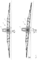
- the distributor linkage 3 shows the distributor linkage 3 when driving straight ahead. No lateral forces act on the inclination sensor.
- the distributor linkage 3 is in the parallel position on the one hand to the ground and on the other hand to a plane perpendicular to the direction of gravity.
- the measured and actual angle between the vertical axis and in the direction of gravitational acceleration (direction of gravity) is 0°.
- the machine 2 is tilted sideways together with the distributor linkage 3, for example by driving on one side in a furrow.
- the reference plane perpendicular to the direction of gravity does not correspond to the soil surface shown schematically, but deviates from the soil surface by the angle beta. The same applies to the normal to the reference plane, which deviates from the direction of gravity by the angle beta.
- the inclination sensor detects the alignment of the distributor linkage 3 in relation to the direction of gravitational acceleration (direction of gravity) perpendicular to the ground, as can be seen in the illustration below.
- gravitational acceleration direction of gravity
- the rate of rotation of the machine 2 about the vertical axis and the driving speed of the machine are recorded and taken into account in the error correction.
- FIG 5 the driving condition is shown during a right turn.
- lateral accelerations or centrifugal forces occur depending on the curve radius and the driving speed, which lead to a deviation of the measured angle from the actual angle.
- FIG. 6 shows the acceleration diagram in the case of a left turn (see 4 ), from which the transverse acceleration and thus the centrifugal force can be seen, which acts on the inclination sensor and leads to a measurement error which is corrected by the invention or the exemplary embodiment according to the invention.
- the linkage is aligned horizontally to the reference plane normal to the direction of gravity and to the natural horizon. Without correction, an incorrect angle alpha to the horizon would be recorded by the inclination sensor (see also 4 , upper representation).
- the error correction takes place in a simplified manner on the basis of the yaw rate about the vertical axis, which is measured by the second sensor device, and the driving speed, which is detected in a manner known per se.
- a correction term is thereby determined which corrects the deviation of the measurement acceleration a M from the gravitational acceleration a G .
- a corresponding correction algorithm is stored in the data processing device.
- the inventions or the above-mentioned exemplary embodiments are not restricted to the algorithm reproduced below, which is to be understood as a possible example of how the measurement error occurring as a result of the transverse forces can be corrected, taking into account the rate of rotation about the vertical axis and the driving speed of the machine.
Landscapes
- Life Sciences & Earth Sciences (AREA)
- Engineering & Computer Science (AREA)
- Insects & Arthropods (AREA)
- Pest Control & Pesticides (AREA)
- Wood Science & Technology (AREA)
- Zoology (AREA)
- Environmental Sciences (AREA)
- Lifting Devices For Agricultural Implements (AREA)
- Sowing (AREA)
- Control Of Position, Course, Altitude, Or Attitude Of Moving Bodies (AREA)
Claims (13)
- Système de régulation et/ou de commande destiné à une machine agricole (2) ayant une tringlerie d'épandage (3) pour distribuer des matériaux, tels que des engrais, des produits phytosanitaires ou des semences, qui peut pivoter autour d'au moins un axe de rotation s'étendant dans le sens de la marche, avec au moins un premier dispositif de détection pour déterminer l'inclinaison de la tringlerie d'épandage (3) et un dispositif de traitement de données pour traiter les signaux de capteur, caractérisé par au moins un deuxième dispositif de détection pour déterminer la force centrifuge FF et/ou l'accélération centrifuge aF , qui agit sur le premier dispositif de détection lors du virage de la machine, le dispositif de traitement de données étant conçu de telle sorte qu'une erreur de mesure d'inclinaison du premier dispositif de détection peut être corrigée sur la base des signaux de capteur du deuxième dispositif de détection.
- Système selon la revendication 1
caractérisé en ce que le moyen de traitement de données est adapté à la vitesse de déplacement de la machine (2) qui est prise en compte dans la correction d'erreur sur la base des signaux de capteur du second dispositif de détection. - Système selon la revendication 2
caractérisé en ce que le dispositif de traitement de données est adapté pour factoriser la vitesse de déplacement, la factorisation étant ajustable. - Système selon l'une des revendications précédentes
caractérisé en ce que le moyen de traitement de données est adapté pour traiter un angle de braquage de la machine (2) qui est pris en compte dans la correction d'erreur sur la base des signaux de capteur du second dispositif de détection. - Système selon l'une des revendications précédentes
caractérisé en ce que le second dispositif de détection comprend un capteur de vitesse de rotation adapté pour mesurer la vitesse de rotation de la tringlerie d'épandage et/ou de la machine autour de l'axe vertical. - Système selon l'une des revendications précédentes
caractérisé en ce que le premier dispositif de détection comprend un capteur d'inclinaison ou un capteur d'accélération pour déterminer l'inclinaison de la tringlerie d'épandage (3). - Système selon l'une des revendications précédentes
caractérisé en ce qu'au moins un troisième dispositif de détection est prévu pour déterminer la distance de la tringlerie d'épandage (3) par rapport au sol et/ou à la végétation et/ou à des obstacles. - Système selon l'une des revendications précédentes
caractérisé en ce que le dispositif de traitement de données est configuré pour un mode automatique, respectivement pour le réglage de la hauteur et/ou de l'inclinaison de la tringlerie d'épandage (3), et pour un mode de surmultiplication, en particulier un mode de surmultiplication manuel, respectivement pour le réglage de la hauteur et/ou de l'inclinaison de la tringlerie d'épandage (3), le dispositif de traitement de données réglant, en mode automatique, la hauteur totale et/ou l'inclinaison totale de la tringlerie d'épandage (3) et, en mode de surmultiplication, surmultipliant, notamment manuellement, au moins un paramètre de régulation du mode automatique qui est actif en mode de surmultiplication. - Système selon l'une des revendications précédentes
caractérisé en ce que le dispositif de traitement de données est configuré pour un mode manuel avec transmission de force rigide sur la tringlerie d'épandage (3), une valeur d'inclinaison actuelle de la tringlerie d'épandage (3) étant reprise comme nouvelle valeur de consigne d'inclinaison lors d'un passage en un mode de découplage avec une tringlerie d'épandage (3) découplée, en particulier en mode automatique et/ou en mode de surmultiplication. - Machine agricole d'épandage de produits tels que des engrais, des produits phytosanitaires ou des semences, comprenant une tringlerie d'épandage (3) et un système de régulation et/ou de commande selon l'une quelconque des revendications précédentes.
- Machine selon la revendication 10
caractérisée en ce que le deuxième dispositif de détection est disposé sur la machine ou sur la tringlerie d'épandage (3) pour déterminer la force centrifuge FF et/ou l'accélération centrifuge aF , qui agit sur le premier dispositif de détection lors d'une conduite en virage de la machine. - Procédé pour faire fonctionner une machine agricole (2), dans lequel un matériau, tel qu'un engrais, un produit phytosanitaire ou des semences, est épandu depuis un réservoir (5) par une tringlerie d'épandage (3), dans lequel, dans un mode de découplage avec une tringlerie d'épandage (3) découplée, en particulier dans un mode de surmultiplication, est réglé sur une valeur d'inclinaison absolue de la tringlerie d'épandage (3) par rapport au sens de la gravité sur la base de signaux de capteur d'au moins un premier dispositif de détection pour déterminer l'inclinaison de la tringlerie d'épandage (3), et lors d'une conduite en virage, une erreur de mesure du premier dispositif de détection est corrigée sur la base de signaux de capteur d'au moins un deuxième dispositif de détection pour déterminer la force centrifuge FF et/ou l'accélération centrifuge aF , qui agit sur le premier dispositif de détection lors de la conduite en virage de la machine.
- Procédé selon la revendication 12
caractérisé en ce que la vitesse de déplacement et/ou l'angle de braquage de la machine (2) sont pris en compte dans la correction d'erreur sur la base des signaux de capteur du deuxième dispositif de détection.
Applications Claiming Priority (2)
| Application Number | Priority Date | Filing Date | Title |
|---|---|---|---|
| DE102016109513.3A DE102016109513A1 (de) | 2016-05-24 | 2016-05-24 | Regel- und/oder Steuersystem, landwirtschaftliche Maschine mit einem solchen System und Verfahren zum Betreiben einer landwirtschaftlichen Maschine |
| PCT/EP2017/060501 WO2017202581A1 (fr) | 2016-05-24 | 2017-05-03 | Système de régulation et/ou de commande, machine agricole comprenant un tel système et procédé permettant de faire fonctionner une machine agricole |
Publications (2)
| Publication Number | Publication Date |
|---|---|
| EP3462855A1 EP3462855A1 (fr) | 2019-04-10 |
| EP3462855B1 true EP3462855B1 (fr) | 2023-08-23 |
Family
ID=58664716
Family Applications (1)
| Application Number | Title | Priority Date | Filing Date |
|---|---|---|---|
| EP17720807.1A Active EP3462855B1 (fr) | 2016-05-24 | 2017-05-03 | Système de régulation et/ou de commande, machine agricole comprenant un tel système et procédé permettant de faire fonctionner une machine agricole |
Country Status (8)
| Country | Link |
|---|---|
| US (1) | US11375706B2 (fr) |
| EP (1) | EP3462855B1 (fr) |
| AR (1) | AR108573A1 (fr) |
| BR (1) | BR112018073922B1 (fr) |
| DE (1) | DE102016109513A1 (fr) |
| DK (1) | DK3462855T3 (fr) |
| PL (1) | PL3462855T3 (fr) |
| WO (1) | WO2017202581A1 (fr) |
Families Citing this family (18)
| Publication number | Priority date | Publication date | Assignee | Title |
|---|---|---|---|---|
| DE102019129206B4 (de) * | 2019-10-29 | 2024-12-12 | Horsch Leeb Application Systems Gmbh | Selbstfahrende und/oder mittels Zugfahrzeug gezogene Landmaschine und Verfahren zur Steuerung und/oder Regelung einer Höhenlage eines Verteilgestänges einer derartigen Landmaschine |
| US11523555B2 (en) | 2019-12-24 | 2022-12-13 | Cnh Industrial America Llc | Particle delivery system of an agricultural row unit |
| US11564344B2 (en) | 2019-12-24 | 2023-01-31 | Cnh Industrial America Llc | Particle delivery system of an agricultural row unit |
| US11589500B2 (en) | 2019-12-24 | 2023-02-28 | Cnh Industrial America Llc | Particle delivery system of an agricultural row unit |
| US11582899B2 (en) | 2019-12-24 | 2023-02-21 | Cnh Industrial America Llc | Particle delivery system of an agricultural row unit |
| US11553638B2 (en) | 2019-12-24 | 2023-01-17 | Cnh Industrial America Llc | Particle delivery system of an agricultural row unit |
| US11490558B2 (en) | 2019-12-24 | 2022-11-08 | Cnh Industrial America Llc | Particle delivery system of an agricultural row unit |
| US11523556B2 (en) | 2019-12-24 | 2022-12-13 | Cnh Industrial America Llc | Particle delivery system of an agricultural row unit |
| US11564346B2 (en) | 2019-12-24 | 2023-01-31 | Cnh Industrial America Llc | Particle delivery system of an agricultural row unit |
| US11553639B2 (en) | 2019-12-24 | 2023-01-17 | Cnh Industrial America Llc | Particle delivery system of an agricultural row unit |
| US11596095B2 (en) | 2019-12-24 | 2023-03-07 | Cnh Industrial America Llc | Particle delivery system of an agricultural row unit |
| US11483963B2 (en) | 2019-12-24 | 2022-11-01 | Cnh Industrial America Llc | Particle delivery system of an agricultural row unit |
| US11516958B2 (en) | 2019-12-24 | 2022-12-06 | Cnh Industrial America Llc | Particle delivery system of an agricultural row unit |
| DE102020127684A1 (de) * | 2020-10-21 | 2022-04-21 | Amazonen-Werke H. Dreyer SE & Co. KG | Landwirtschaftliches Gerät mit einem Gestänge |
| CN112155002A (zh) * | 2020-10-29 | 2021-01-01 | 常州机电职业技术学院 | 一种喷杆臂自动平衡控制机构、喷雾机及其工作方法 |
| US11793187B2 (en) * | 2021-01-15 | 2023-10-24 | Cnh Industrial America Llc | System and method for monitoring agricultural fluid deposition rate during a spraying operation |
| DE102023130032A1 (de) | 2023-10-31 | 2025-04-30 | Kornbrennerei Icking e.K. | Vorrichtungen zur Ausbringung mindestens eines flüssigen Mediums; Verfahren zur Ausbringung mindestens eines flüssigen Mediums |
| US12532796B2 (en) * | 2024-02-26 | 2026-01-27 | Cnh Industrial America Llc | System and method for an agricultural machine |
Family Cites Families (12)
| Publication number | Priority date | Publication date | Assignee | Title |
|---|---|---|---|---|
| US5988528A (en) * | 1996-12-30 | 1999-11-23 | Case Corporation | Self-centering boom |
| US7162348B2 (en) * | 2002-12-11 | 2007-01-09 | Hemisphere Gps Llc | Articulated equipment position control system and method |
| JP2004262292A (ja) * | 2003-02-28 | 2004-09-24 | Yanmar Co Ltd | コンバイン |
| DE102011052705A1 (de) * | 2011-08-15 | 2013-02-21 | Amazonen-Werke H. Dreyer Gmbh & Co. Kg | Landwirtschaftliche Verteilmaschine |
| US8942893B2 (en) * | 2012-09-07 | 2015-01-27 | Trimble Navigation Limited | Predictive boom shape adjustment |
| EP3912468B1 (fr) | 2013-08-22 | 2024-04-03 | HORSCH LEEB Application Systems GmbH | Procédé de commande et/ou de réglage du mouvement d'un dispositif d'épandage agricole |
| DK3007553T4 (da) * | 2013-09-18 | 2023-02-27 | Horsch Leeb Application Systems Gmbh | Indretning til spredning af flydende og/eller faste, virksomme stoffer samt fremgangsmåde til styring af en sådan indretning |
| EP3065530B1 (fr) * | 2013-11-10 | 2022-03-30 | HORSCH LEEB Application Systems GmbH | Dispositif pour distribuer des substances actives liquides et/ou solides et procédé de commande d'un tel dispositif |
| DE102015102080A1 (de) * | 2015-02-13 | 2016-08-18 | Horsch Leeb Application Systems Gmbh | Vorrichtung zum Ausbringen von Flüssigkeiten und Verfahren zur Bewegungssteuerung wenigstens zweier Auslegerarme einer landwirtschaftlichen Feldspritze |
| DE102015102422A1 (de) * | 2015-02-20 | 2016-08-25 | Horsch Leeb Application Systems Gmbh | Verfahren zur Bewegungssteuerung und/oder Regelung einer landwirtschaftlichen Verteilvorrichtung |
| GB201508250D0 (en) * | 2015-05-14 | 2015-06-24 | Norac Systems Internat Inc | Control system and method for a suspended boom sprayer |
| US10499561B2 (en) * | 2015-07-29 | 2019-12-10 | Cnh Industrial America Llc | Boom adjustment system and method |
-
2016
- 2016-05-24 DE DE102016109513.3A patent/DE102016109513A1/de not_active Withdrawn
-
2017
- 2017-05-03 EP EP17720807.1A patent/EP3462855B1/fr active Active
- 2017-05-03 US US16/304,169 patent/US11375706B2/en active Active
- 2017-05-03 PL PL17720807.1T patent/PL3462855T3/pl unknown
- 2017-05-03 DK DK17720807.1T patent/DK3462855T3/da active
- 2017-05-03 WO PCT/EP2017/060501 patent/WO2017202581A1/fr not_active Ceased
- 2017-05-03 BR BR112018073922-7A patent/BR112018073922B1/pt active IP Right Grant
- 2017-05-23 AR ARP170101395A patent/AR108573A1/es active IP Right Grant
Also Published As
| Publication number | Publication date |
|---|---|
| WO2017202581A1 (fr) | 2017-11-30 |
| BR112018073922B1 (pt) | 2022-11-29 |
| AR108573A1 (es) | 2018-09-05 |
| EP3462855A1 (fr) | 2019-04-10 |
| DK3462855T3 (da) | 2023-11-27 |
| US20200281182A1 (en) | 2020-09-10 |
| DE102016109513A1 (de) | 2017-11-30 |
| US11375706B2 (en) | 2022-07-05 |
| PL3462855T3 (pl) | 2024-02-19 |
| BR112018073922A2 (pt) | 2019-02-26 |
Similar Documents
| Publication | Publication Date | Title |
|---|---|---|
| EP3462855B1 (fr) | Système de régulation et/ou de commande, machine agricole comprenant un tel système et procédé permettant de faire fonctionner une machine agricole | |
| EP3007553B1 (fr) | Dispositif de distribution de substances actives liquides et/ou solides et procédé de commande d'un tel dispositif | |
| EP3035795B1 (fr) | Pulvérisateur pour épandre des substances actives liquides et/ou solides et contrôle d'un tel | |
| EP3065530B1 (fr) | Dispositif pour distribuer des substances actives liquides et/ou solides et procédé de commande d'un tel dispositif | |
| EP2591657B1 (fr) | Dispositif mobile destiné à sortir des agents actifs liquides et/ou solides et procédé de commande du dispositif | |
| EP3064061A1 (fr) | Dispositif d'extraction de liquides et/ou d'agents actifs solides et procede de commande d'un tel dispositif | |
| DE102019129206B4 (de) | Selbstfahrende und/oder mittels Zugfahrzeug gezogene Landmaschine und Verfahren zur Steuerung und/oder Regelung einer Höhenlage eines Verteilgestänges einer derartigen Landmaschine | |
| EP3815528A1 (fr) | Machine agricole dotée d'un système de calcul d'un relief du sol et procédé de fonctionnement d'une machine agricole | |
| EP3141114B1 (fr) | Systeme d'epandage et procede d'epandage | |
| EP2936980A1 (fr) | Pulvérisateur à cultures | |
| DE102015119145A1 (de) | Regel- und/oder Steuersystem für eine landwirtschaftliche Maschine | |
| EP3732945A1 (fr) | Technique de la génération d'un profil de terrain à l'aide d'une machine agricole | |
| EP3276080B1 (fr) | Système de capteurs pour une finisseuse de route | |
| EP3466257B1 (fr) | Machine d'épandage agricole et procédé de commande d'une telle machine d'épandage | |
| EP4014732B1 (fr) | Machine agricole à épandre et procédé de commande et/ou de régulation d'une machine agricole à épandre | |
| EP3895532B1 (fr) | Système pour une machine agricole de travail, procédé de détermination d'une position des éléments de travail, ainsi que machine agricole de travail | |
| DE102018103862A1 (de) | Aufhängung für eine landwirtschaftliche Maschine und Verfahren zum Betreiben einer landwirtschaftlichen Maschine | |
| DE102019127305A1 (de) | Landwirtschaftliche Verteilmaschine, vorzugsweise eine Feldspritze oder einen pneumatischen Düngerstreuer | |
| DE102022122182A1 (de) | Landwirtschaftliche Verteilmaschine mit einem Verteilgestänge und Verfahren zur Lagesteuerung eines solchen Verteilgestänges | |
| EP3469897B1 (fr) | Machine d'épandage agricole et procédé de commande d'une telle machine d'épandage |
Legal Events
| Date | Code | Title | Description |
|---|---|---|---|
| STAA | Information on the status of an ep patent application or granted ep patent |
Free format text: STATUS: UNKNOWN |
|
| STAA | Information on the status of an ep patent application or granted ep patent |
Free format text: STATUS: THE INTERNATIONAL PUBLICATION HAS BEEN MADE |
|
| PUAI | Public reference made under article 153(3) epc to a published international application that has entered the european phase |
Free format text: ORIGINAL CODE: 0009012 |
|
| STAA | Information on the status of an ep patent application or granted ep patent |
Free format text: STATUS: REQUEST FOR EXAMINATION WAS MADE |
|
| 17P | Request for examination filed |
Effective date: 20180820 |
|
| AK | Designated contracting states |
Kind code of ref document: A1 Designated state(s): AL AT BE BG CH CY CZ DE DK EE ES FI FR GB GR HR HU IE IS IT LI LT LU LV MC MK MT NL NO PL PT RO RS SE SI SK SM TR |
|
| AX | Request for extension of the european patent |
Extension state: BA ME |
|
| DAV | Request for validation of the european patent (deleted) | ||
| DAX | Request for extension of the european patent (deleted) | ||
| RAP3 | Party data changed (applicant data changed or rights of an application transferred) |
Owner name: AMAZONEN-WERK H. DREYER SE & CO. KG Owner name: HYDAC SYSTEMS & SERVICES GMBH |
|
| RAP3 | Party data changed (applicant data changed or rights of an application transferred) |
Owner name: AMAZONEN-WERKE H. DREYER SE & CO. KG Owner name: HYDAC SYSTEMS & SERVICES GMBH |
|
| GRAP | Despatch of communication of intention to grant a patent |
Free format text: ORIGINAL CODE: EPIDOSNIGR1 |
|
| STAA | Information on the status of an ep patent application or granted ep patent |
Free format text: STATUS: GRANT OF PATENT IS INTENDED |
|
| INTG | Intention to grant announced |
Effective date: 20230331 |
|
| P01 | Opt-out of the competence of the unified patent court (upc) registered |
Effective date: 20230523 |
|
| GRAS | Grant fee paid |
Free format text: ORIGINAL CODE: EPIDOSNIGR3 |
|
| GRAA | (expected) grant |
Free format text: ORIGINAL CODE: 0009210 |
|
| STAA | Information on the status of an ep patent application or granted ep patent |
Free format text: STATUS: THE PATENT HAS BEEN GRANTED |
|
| AK | Designated contracting states |
Kind code of ref document: B1 Designated state(s): AL AT BE BG CH CY CZ DE DK EE ES FI FR GB GR HR HU IE IS IT LI LT LU LV MC MK MT NL NO PL PT RO RS SE SI SK SM TR |
|
| REG | Reference to a national code |
Ref country code: GB Ref legal event code: FG4D Free format text: NOT ENGLISH |
|
| REG | Reference to a national code |
Ref country code: CH Ref legal event code: EP |
|
| REG | Reference to a national code |
Ref country code: DE Ref legal event code: R096 Ref document number: 502017015264 Country of ref document: DE |
|
| REG | Reference to a national code |
Ref country code: IE Ref legal event code: FG4D Free format text: LANGUAGE OF EP DOCUMENT: GERMAN |
|
| REG | Reference to a national code |
Ref country code: NL Ref legal event code: FP |
|
| REG | Reference to a national code |
Ref country code: DK Ref legal event code: T3 Effective date: 20231123 |
|
| REG | Reference to a national code |
Ref country code: LT Ref legal event code: MG9D |
|
| PG25 | Lapsed in a contracting state [announced via postgrant information from national office to epo] |
Ref country code: GR Free format text: LAPSE BECAUSE OF FAILURE TO SUBMIT A TRANSLATION OF THE DESCRIPTION OR TO PAY THE FEE WITHIN THE PRESCRIBED TIME-LIMIT Effective date: 20231124 |
|
| PG25 | Lapsed in a contracting state [announced via postgrant information from national office to epo] |
Ref country code: IS Free format text: LAPSE BECAUSE OF FAILURE TO SUBMIT A TRANSLATION OF THE DESCRIPTION OR TO PAY THE FEE WITHIN THE PRESCRIBED TIME-LIMIT Effective date: 20231223 |
|
| PG25 | Lapsed in a contracting state [announced via postgrant information from national office to epo] |
Ref country code: SE Free format text: LAPSE BECAUSE OF FAILURE TO SUBMIT A TRANSLATION OF THE DESCRIPTION OR TO PAY THE FEE WITHIN THE PRESCRIBED TIME-LIMIT Effective date: 20230823 Ref country code: RS Free format text: LAPSE BECAUSE OF FAILURE TO SUBMIT A TRANSLATION OF THE DESCRIPTION OR TO PAY THE FEE WITHIN THE PRESCRIBED TIME-LIMIT Effective date: 20230823 Ref country code: PT Free format text: LAPSE BECAUSE OF FAILURE TO SUBMIT A TRANSLATION OF THE DESCRIPTION OR TO PAY THE FEE WITHIN THE PRESCRIBED TIME-LIMIT Effective date: 20231226 Ref country code: NO Free format text: LAPSE BECAUSE OF FAILURE TO SUBMIT A TRANSLATION OF THE DESCRIPTION OR TO PAY THE FEE WITHIN THE PRESCRIBED TIME-LIMIT Effective date: 20231123 Ref country code: LV Free format text: LAPSE BECAUSE OF FAILURE TO SUBMIT A TRANSLATION OF THE DESCRIPTION OR TO PAY THE FEE WITHIN THE PRESCRIBED TIME-LIMIT Effective date: 20230823 Ref country code: LT Free format text: LAPSE BECAUSE OF FAILURE TO SUBMIT A TRANSLATION OF THE DESCRIPTION OR TO PAY THE FEE WITHIN THE PRESCRIBED TIME-LIMIT Effective date: 20230823 Ref country code: IS Free format text: LAPSE BECAUSE OF FAILURE TO SUBMIT A TRANSLATION OF THE DESCRIPTION OR TO PAY THE FEE WITHIN THE PRESCRIBED TIME-LIMIT Effective date: 20231223 Ref country code: HR Free format text: LAPSE BECAUSE OF FAILURE TO SUBMIT A TRANSLATION OF THE DESCRIPTION OR TO PAY THE FEE WITHIN THE PRESCRIBED TIME-LIMIT Effective date: 20230823 Ref country code: GR Free format text: LAPSE BECAUSE OF FAILURE TO SUBMIT A TRANSLATION OF THE DESCRIPTION OR TO PAY THE FEE WITHIN THE PRESCRIBED TIME-LIMIT Effective date: 20231124 Ref country code: FI Free format text: LAPSE BECAUSE OF FAILURE TO SUBMIT A TRANSLATION OF THE DESCRIPTION OR TO PAY THE FEE WITHIN THE PRESCRIBED TIME-LIMIT Effective date: 20230823 |
|
| PG25 | Lapsed in a contracting state [announced via postgrant information from national office to epo] |
Ref country code: ES Free format text: LAPSE BECAUSE OF FAILURE TO SUBMIT A TRANSLATION OF THE DESCRIPTION OR TO PAY THE FEE WITHIN THE PRESCRIBED TIME-LIMIT Effective date: 20230823 |
|
| PG25 | Lapsed in a contracting state [announced via postgrant information from national office to epo] |
Ref country code: SM Free format text: LAPSE BECAUSE OF FAILURE TO SUBMIT A TRANSLATION OF THE DESCRIPTION OR TO PAY THE FEE WITHIN THE PRESCRIBED TIME-LIMIT Effective date: 20230823 Ref country code: RO Free format text: LAPSE BECAUSE OF FAILURE TO SUBMIT A TRANSLATION OF THE DESCRIPTION OR TO PAY THE FEE WITHIN THE PRESCRIBED TIME-LIMIT Effective date: 20230823 Ref country code: ES Free format text: LAPSE BECAUSE OF FAILURE TO SUBMIT A TRANSLATION OF THE DESCRIPTION OR TO PAY THE FEE WITHIN THE PRESCRIBED TIME-LIMIT Effective date: 20230823 Ref country code: EE Free format text: LAPSE BECAUSE OF FAILURE TO SUBMIT A TRANSLATION OF THE DESCRIPTION OR TO PAY THE FEE WITHIN THE PRESCRIBED TIME-LIMIT Effective date: 20230823 Ref country code: SK Free format text: LAPSE BECAUSE OF FAILURE TO SUBMIT A TRANSLATION OF THE DESCRIPTION OR TO PAY THE FEE WITHIN THE PRESCRIBED TIME-LIMIT Effective date: 20230823 |
|
| REG | Reference to a national code |
Ref country code: DE Ref legal event code: R097 Ref document number: 502017015264 Country of ref document: DE |
|
| PG25 | Lapsed in a contracting state [announced via postgrant information from national office to epo] |
Ref country code: IT Free format text: LAPSE BECAUSE OF FAILURE TO SUBMIT A TRANSLATION OF THE DESCRIPTION OR TO PAY THE FEE WITHIN THE PRESCRIBED TIME-LIMIT Effective date: 20230823 |
|
| PLBE | No opposition filed within time limit |
Free format text: ORIGINAL CODE: 0009261 |
|
| STAA | Information on the status of an ep patent application or granted ep patent |
Free format text: STATUS: NO OPPOSITION FILED WITHIN TIME LIMIT |
|
| 26N | No opposition filed |
Effective date: 20240524 |
|
| PG25 | Lapsed in a contracting state [announced via postgrant information from national office to epo] |
Ref country code: SI Free format text: LAPSE BECAUSE OF FAILURE TO SUBMIT A TRANSLATION OF THE DESCRIPTION OR TO PAY THE FEE WITHIN THE PRESCRIBED TIME-LIMIT Effective date: 20230823 |
|
| PG25 | Lapsed in a contracting state [announced via postgrant information from national office to epo] |
Ref country code: BG Free format text: LAPSE BECAUSE OF FAILURE TO SUBMIT A TRANSLATION OF THE DESCRIPTION OR TO PAY THE FEE WITHIN THE PRESCRIBED TIME-LIMIT Effective date: 20230823 |
|
| PG25 | Lapsed in a contracting state [announced via postgrant information from national office to epo] |
Ref country code: BG Free format text: LAPSE BECAUSE OF FAILURE TO SUBMIT A TRANSLATION OF THE DESCRIPTION OR TO PAY THE FEE WITHIN THE PRESCRIBED TIME-LIMIT Effective date: 20230823 |
|
| REG | Reference to a national code |
Ref country code: CH Ref legal event code: PL |
|
| PG25 | Lapsed in a contracting state [announced via postgrant information from national office to epo] |
Ref country code: MC Free format text: LAPSE BECAUSE OF FAILURE TO SUBMIT A TRANSLATION OF THE DESCRIPTION OR TO PAY THE FEE WITHIN THE PRESCRIBED TIME-LIMIT Effective date: 20230823 |
|
| PG25 | Lapsed in a contracting state [announced via postgrant information from national office to epo] |
Ref country code: LU Free format text: LAPSE BECAUSE OF NON-PAYMENT OF DUE FEES Effective date: 20240503 |
|
| GBPC | Gb: european patent ceased through non-payment of renewal fee |
Effective date: 20240503 |
|
| PG25 | Lapsed in a contracting state [announced via postgrant information from national office to epo] |
Ref country code: MC Free format text: LAPSE BECAUSE OF FAILURE TO SUBMIT A TRANSLATION OF THE DESCRIPTION OR TO PAY THE FEE WITHIN THE PRESCRIBED TIME-LIMIT Effective date: 20230823 Ref country code: LU Free format text: LAPSE BECAUSE OF NON-PAYMENT OF DUE FEES Effective date: 20240503 Ref country code: CH Free format text: LAPSE BECAUSE OF NON-PAYMENT OF DUE FEES Effective date: 20240531 |
|
| REG | Reference to a national code |
Ref country code: BE Ref legal event code: MM Effective date: 20240531 |
|
| PG25 | Lapsed in a contracting state [announced via postgrant information from national office to epo] |
Ref country code: IE Free format text: LAPSE BECAUSE OF NON-PAYMENT OF DUE FEES Effective date: 20240503 |
|
| PG25 | Lapsed in a contracting state [announced via postgrant information from national office to epo] |
Ref country code: BE Free format text: LAPSE BECAUSE OF NON-PAYMENT OF DUE FEES Effective date: 20240531 |
|
| PG25 | Lapsed in a contracting state [announced via postgrant information from national office to epo] |
Ref country code: GB Free format text: LAPSE BECAUSE OF NON-PAYMENT OF DUE FEES Effective date: 20240503 |
|
| PGFP | Annual fee paid to national office [announced via postgrant information from national office to epo] |
Ref country code: NL Payment date: 20250523 Year of fee payment: 9 |
|
| PGFP | Annual fee paid to national office [announced via postgrant information from national office to epo] |
Ref country code: PL Payment date: 20250430 Year of fee payment: 9 Ref country code: DE Payment date: 20250528 Year of fee payment: 9 |
|
| PGFP | Annual fee paid to national office [announced via postgrant information from national office to epo] |
Ref country code: DK Payment date: 20250520 Year of fee payment: 9 |
|
| REG | Reference to a national code |
Ref country code: AT Ref legal event code: MM01 Ref document number: 1601452 Country of ref document: AT Kind code of ref document: T Effective date: 20240503 |
|
| PGFP | Annual fee paid to national office [announced via postgrant information from national office to epo] |
Ref country code: FR Payment date: 20250520 Year of fee payment: 9 |
|
| PG25 | Lapsed in a contracting state [announced via postgrant information from national office to epo] |
Ref country code: AT Free format text: LAPSE BECAUSE OF NON-PAYMENT OF DUE FEES Effective date: 20240503 |
|
| PGFP | Annual fee paid to national office [announced via postgrant information from national office to epo] |
Ref country code: CZ Payment date: 20250430 Year of fee payment: 9 |
|
| PG25 | Lapsed in a contracting state [announced via postgrant information from national office to epo] |
Ref country code: CY Free format text: LAPSE BECAUSE OF FAILURE TO SUBMIT A TRANSLATION OF THE DESCRIPTION OR TO PAY THE FEE WITHIN THE PRESCRIBED TIME-LIMIT; INVALID AB INITIO Effective date: 20170503 |
|
| PG25 | Lapsed in a contracting state [announced via postgrant information from national office to epo] |
Ref country code: HU Free format text: LAPSE BECAUSE OF FAILURE TO SUBMIT A TRANSLATION OF THE DESCRIPTION OR TO PAY THE FEE WITHIN THE PRESCRIBED TIME-LIMIT; INVALID AB INITIO Effective date: 20170503 |