EP3463005B1 - Kapselsystem zur herstellung eines getränks - Google Patents
Kapselsystem zur herstellung eines getränks Download PDFInfo
- Publication number
- EP3463005B1 EP3463005B1 EP17729824.7A EP17729824A EP3463005B1 EP 3463005 B1 EP3463005 B1 EP 3463005B1 EP 17729824 A EP17729824 A EP 17729824A EP 3463005 B1 EP3463005 B1 EP 3463005B1
- Authority
- EP
- European Patent Office
- Prior art keywords
- capsule
- beverage
- receiving unit
- capsule system
- carriage
- Prior art date
- Legal status (The legal status is an assumption and is not a legal conclusion. Google has not performed a legal analysis and makes no representation as to the accuracy of the status listed.)
- Not-in-force
Links
- 239000002775 capsule Substances 0.000 title claims description 305
- 235000013361 beverage Nutrition 0.000 title claims description 66
- 238000012545 processing Methods 0.000 claims description 49
- 239000004615 ingredient Substances 0.000 claims description 41
- 238000004519 manufacturing process Methods 0.000 claims description 38
- 239000000203 mixture Substances 0.000 claims description 19
- 230000004044 response Effects 0.000 claims description 9
- 239000000126 substance Substances 0.000 claims description 9
- 230000001681 protective effect Effects 0.000 claims description 7
- 238000000034 method Methods 0.000 claims description 5
- 230000008569 process Effects 0.000 claims description 4
- 238000001514 detection method Methods 0.000 claims description 3
- 230000005484 gravity Effects 0.000 claims description 2
- 238000005286 illumination Methods 0.000 claims 4
- 230000000694 effects Effects 0.000 claims 1
- 239000007788 liquid Substances 0.000 description 9
- 238000012546 transfer Methods 0.000 description 9
- 230000003993 interaction Effects 0.000 description 8
- 238000003780 insertion Methods 0.000 description 6
- 230000037431 insertion Effects 0.000 description 6
- 238000002360 preparation method Methods 0.000 description 4
- 230000002829 reductive effect Effects 0.000 description 4
- XLYOFNOQVPJJNP-UHFFFAOYSA-N water Substances O XLYOFNOQVPJJNP-UHFFFAOYSA-N 0.000 description 4
- 239000000843 powder Substances 0.000 description 3
- 230000001476 alcoholic effect Effects 0.000 description 2
- 230000005540 biological transmission Effects 0.000 description 2
- 238000010586 diagram Methods 0.000 description 2
- 239000000839 emulsion Substances 0.000 description 2
- 239000011521 glass Substances 0.000 description 2
- 235000015122 lemonade Nutrition 0.000 description 2
- 238000002156 mixing Methods 0.000 description 2
- 238000003825 pressing Methods 0.000 description 2
- 239000007787 solid Substances 0.000 description 2
- 230000001960 triggered effect Effects 0.000 description 2
- 235000008733 Citrus aurantifolia Nutrition 0.000 description 1
- LFQSCWFLJHTTHZ-UHFFFAOYSA-N Ethanol Chemical compound CCO LFQSCWFLJHTTHZ-UHFFFAOYSA-N 0.000 description 1
- 241001122767 Theaceae Species 0.000 description 1
- 235000011941 Tilia x europaea Nutrition 0.000 description 1
- 230000004308 accommodation Effects 0.000 description 1
- 230000009471 action Effects 0.000 description 1
- 230000004913 activation Effects 0.000 description 1
- 235000020965 cold beverage Nutrition 0.000 description 1
- 239000003086 colorant Substances 0.000 description 1
- 238000012790 confirmation Methods 0.000 description 1
- 230000001419 dependent effect Effects 0.000 description 1
- 238000013461 design Methods 0.000 description 1
- 230000007613 environmental effect Effects 0.000 description 1
- 238000011010 flushing procedure Methods 0.000 description 1
- 235000011389 fruit/vegetable juice Nutrition 0.000 description 1
- 239000007789 gas Substances 0.000 description 1
- 235000012171 hot beverage Nutrition 0.000 description 1
- 239000011261 inert gas Substances 0.000 description 1
- 239000000463 material Substances 0.000 description 1
- 230000007246 mechanism Effects 0.000 description 1
- 230000036961 partial effect Effects 0.000 description 1
- 230000002093 peripheral effect Effects 0.000 description 1
- 230000009467 reduction Effects 0.000 description 1
- 230000002441 reversible effect Effects 0.000 description 1
- 230000035939 shock Effects 0.000 description 1
- 230000003068 static effect Effects 0.000 description 1
- 239000006188 syrup Substances 0.000 description 1
- 235000020357 syrup Nutrition 0.000 description 1
- 230000000007 visual effect Effects 0.000 description 1
Images


Classifications
-
- A—HUMAN NECESSITIES
- A47—FURNITURE; DOMESTIC ARTICLES OR APPLIANCES; COFFEE MILLS; SPICE MILLS; SUCTION CLEANERS IN GENERAL
- A47J—KITCHEN EQUIPMENT; COFFEE MILLS; SPICE MILLS; APPARATUS FOR MAKING BEVERAGES
- A47J31/00—Apparatus for making beverages
- A47J31/24—Coffee-making apparatus in which hot water is passed through the filter under pressure, i.e. in which the coffee grounds are extracted under pressure
- A47J31/34—Coffee-making apparatus in which hot water is passed through the filter under pressure, i.e. in which the coffee grounds are extracted under pressure with hot water under liquid pressure
- A47J31/36—Coffee-making apparatus in which hot water is passed through the filter under pressure, i.e. in which the coffee grounds are extracted under pressure with hot water under liquid pressure with mechanical pressure-producing means
- A47J31/3604—Coffee-making apparatus in which hot water is passed through the filter under pressure, i.e. in which the coffee grounds are extracted under pressure with hot water under liquid pressure with mechanical pressure-producing means with a mechanism arranged to move the brewing chamber between loading, infusing and ejecting stations
- A47J31/3623—Cartridges being employed
- A47J31/3633—Means to perform transfer from a loading position to an infusing position
-
- A—HUMAN NECESSITIES
- A47—FURNITURE; DOMESTIC ARTICLES OR APPLIANCES; COFFEE MILLS; SPICE MILLS; SUCTION CLEANERS IN GENERAL
- A47J—KITCHEN EQUIPMENT; COFFEE MILLS; SPICE MILLS; APPARATUS FOR MAKING BEVERAGES
- A47J31/00—Apparatus for making beverages
- A47J31/24—Coffee-making apparatus in which hot water is passed through the filter under pressure, i.e. in which the coffee grounds are extracted under pressure
- A47J31/34—Coffee-making apparatus in which hot water is passed through the filter under pressure, i.e. in which the coffee grounds are extracted under pressure with hot water under liquid pressure
- A47J31/36—Coffee-making apparatus in which hot water is passed through the filter under pressure, i.e. in which the coffee grounds are extracted under pressure with hot water under liquid pressure with mechanical pressure-producing means
- A47J31/3604—Coffee-making apparatus in which hot water is passed through the filter under pressure, i.e. in which the coffee grounds are extracted under pressure with hot water under liquid pressure with mechanical pressure-producing means with a mechanism arranged to move the brewing chamber between loading, infusing and ejecting stations
- A47J31/3623—Cartridges being employed
-
- A—HUMAN NECESSITIES
- A47—FURNITURE; DOMESTIC ARTICLES OR APPLIANCES; COFFEE MILLS; SPICE MILLS; SUCTION CLEANERS IN GENERAL
- A47J—KITCHEN EQUIPMENT; COFFEE MILLS; SPICE MILLS; APPARATUS FOR MAKING BEVERAGES
- A47J31/00—Apparatus for making beverages
- A47J31/40—Beverage-making apparatus with dispensing means for adding a measured quantity of ingredients, e.g. coffee, water, sugar, cocoa, milk, tea
- A47J31/407—Beverage-making apparatus with dispensing means for adding a measured quantity of ingredients, e.g. coffee, water, sugar, cocoa, milk, tea with ingredient-containing cartridges; Cartridge-perforating means
-
- A—HUMAN NECESSITIES
- A47—FURNITURE; DOMESTIC ARTICLES OR APPLIANCES; COFFEE MILLS; SPICE MILLS; SUCTION CLEANERS IN GENERAL
- A47J—KITCHEN EQUIPMENT; COFFEE MILLS; SPICE MILLS; APPARATUS FOR MAKING BEVERAGES
- A47J31/00—Apparatus for making beverages
- A47J31/44—Parts or details or accessories of beverage-making apparatus
- A47J31/52—Alarm-clock-controlled mechanisms for coffee- or tea-making apparatus ; Timers for coffee- or tea-making apparatus; Electronic control devices for coffee- or tea-making apparatus
- A47J31/525—Alarm-clock-controlled mechanisms for coffee- or tea-making apparatus ; Timers for coffee- or tea-making apparatus; Electronic control devices for coffee- or tea-making apparatus the electronic control being based on monitoring of specific process parameters
- A47J31/5251—Alarm-clock-controlled mechanisms for coffee- or tea-making apparatus ; Timers for coffee- or tea-making apparatus; Electronic control devices for coffee- or tea-making apparatus the electronic control being based on monitoring of specific process parameters of pressure
-
- B—PERFORMING OPERATIONS; TRANSPORTING
- B65—CONVEYING; PACKING; STORING; HANDLING THIN OR FILAMENTARY MATERIAL
- B65D—CONTAINERS FOR STORAGE OR TRANSPORT OF ARTICLES OR MATERIALS, e.g. BAGS, BARRELS, BOTTLES, BOXES, CANS, CARTONS, CRATES, DRUMS, JARS, TANKS, HOPPERS, FORWARDING CONTAINERS; ACCESSORIES, CLOSURES, OR FITTINGS THEREFOR; PACKAGING ELEMENTS; PACKAGES
- B65D85/00—Containers, packaging elements or packages, specially adapted for particular articles or materials
- B65D85/70—Containers, packaging elements or packages, specially adapted for particular articles or materials for materials not otherwise provided for
- B65D85/804—Disposable containers or packages with contents which are mixed, infused or dissolved in situ, i.e. without having been previously removed from the package
- B65D85/8043—Packages adapted to allow liquid to pass through the contents
Definitions
- the invention relates to a system for producing an individually portioned beverage based on a capsule with ingredients for such a beverage.
- capsule-based beverage systems are used in professional applications and in consumer applications. Based on the content of capsules, hot drinks such as coffee or tea and cold drinks such as lemonades etc. can be produced.
- a capsule usually contains ingredients (e.g. a syrup, a powder, etc.) that have to be dissolved in a liquid to be added separately (especially in water) in order to produce the selected drink.
- the capsule-based beverage systems (referred to in this document as capsule systems) use the contents of a capsule to prepare the respective beverage in portions and as required.
- a user For the manufacture of a beverage, a user typically inserts a capsule into the capsule system and then causes the contents of the capsule to be mixed with liquid to produce the beverage. A capsule can be inserted or jammed incorrectly, which can lead to problems in the manufacture of a drink.
- Different aspects of systems for producing a beverage are in WO 2012/123 440 A1 , DE 600 21 531 T1 , US 9 155 418 B2 , DE 601 26 287 T2 , EP 0 199 953 B1 , DE 603 09 723 T2 , US 2008/0 203 870 A1 , DE 10 2008 014 233 B4 , DE 10 2007 041 093 A1 described.
- WO 2006/126230 a beverage system with a drawer.
- EP 1 002 490 a beverage system for processing capsules.
- the present document deals with the technical problem of providing a capsule system for producing a beverage which enables a capsule system to be reliably introduced and processed, and thus enables a beverage to be produced reliably.
- a capsule system for producing a beverage can process a capsule that contains ingredients for a portion (e.g. for a glass) of an (alcoholic or non-alcoholic) beverage.
- the capsule system can be used to produce a portion of a beverage from the (in particular substantially all) ingredients of a capsule.
- the capsule system comprises a housing that at least partially encloses an inner region of the capsule system.
- the housing can be cuboid, with four side walls, a floor and a top wall.
- the capsule system can be designed, for example, as a domestic appliance, in particular as a domestic appliance, which e.g. can be placed on a kitchen worktop and / or built into a built-in cupboard.
- the capsule system comprises a receiving unit, which is set up to receive a capsule for producing a beverage.
- the receiving unit can enable a user to transfer a capsule to the capsule system. The capsule is then picked up by the capsule system on the receiving unit and is then typically no longer touched by a user.
- the receiving unit can comprise means (e.g. a recess for a finger) that enable a user to remove a capsule that has already been transferred to the capsule system (e.g. if it was recognized that a capsule for an incorrect type of beverage was inserted).
- the capsule system further comprises conveying means which are set up to convey a capsule received by the receiving unit to a processing position in the interior of the capsule system by means of one or more actuators.
- the one or more actuators can be operated electrically, for example.
- the one or more actuators can comprise one or more electric motors.
- the capsule can be opened at the processing position in order to produce a drink from the contents of the capsule.
- the capsule system can comprise processing means which are set up to open a capsule arranged at the processing position in order to produce a beverage from the contents of the capsule.
- the processing means can e.g. comprise one or more (hollow) needles with which the lid of a capsule can be opened in order to generate access to the contents of the capsule.
- the opened capsule can then optionally be flushed through with a liquid in order to produce a drink from the ingredients.
- the capsule system can comprise an output unit for providing a beverage made from a capsule.
- the capsule system also includes a control unit that is set up to control the manufacturing process of a beverage.
- the control unit is set up to cause the conveying means to convey a first capsule received by the receiving unit to the processing position.
- the control unit can be set up to cause a first drink to be produced from the ingredients of the first capsule.
- the control unit can be set up to cause the processing means to produce a first drink from ingredients of the first capsule and to make it available via the dispensing unit.
- the production of the first beverage can be carried out automatically (i.e. without further user intervention) as soon as the first capsule is at the processing position in the interior of the capsule system.
- the capsule system enables a comfortable and reliable production of a drink based on the contents of a capsule.
- the use of driven means of transport ensures that a capsule is reliably and precisely transported to a specific processing position in the capsule system, so that problems in the manufacturing process (such as incorrect placement of a capsule) can be avoided.
- the use of powered conveyors is particularly advantageous when using multi-chamber capsules (with several chambers for different substances for the production of a drink), since opening and rinsing of such multi-chamber capsules typically requires a particularly precise positioning of the capsule at a certain processing position .
- the capsule system can thus be set up to produce a drink based on a multi-chamber capsule, which comprises several chambers with different substances for producing a drink, which enables the reliable production of complex drinks.
- the multi-chamber capsule may include an outer shell that has an outer bottom, an outer side wall, and an outer lid that define an overall cavity of the multi-chamber capsule.
- the multi-chamber capsule can comprise at least one inner shell, which is arranged within the entire cavity of the capsule and which forms a second chamber for receiving a second volume of a second ingredient.
- a remaining cavity of the multi-chamber capsule is formed by the total cavity minus the at least one inner shell as the first chamber for receiving a first volume of a first ingredient.
- the processing means can be arranged to open the inner shell of the capsule and to create a cavity within the capsule for receiving a mixture which completely comprises the first ingredient and the second ingredient.
- the processing means can be set up to tilt the capsule in order to pour the ingredients, in particular around the ingredient mixture, out of the capsule through an opening in the outer lid. This enables the efficient production of a drink.
- the receiving unit can have a shape that is adapted to a shape of the capsule, so that a capsule can be transferred in a reliable manner.
- a recess in the receiving unit for receiving a capsule can have a contour that corresponds to a contour or an outline of the capsule.
- a capsule can be cylindrical, for example, with differently sized bottom and lid surfaces.
- the receiving unit can comprise an opening or recess which is adapted to the differently sized bottom and lid surfaces of the capsule. In this way, a user can be given a capsule in an intuitive manner with a correct orientation to the capsule system.
- the recording unit can e.g. be arranged on a front wall of the housing.
- An arrangement on the front wall enables a user to be able to transfer a capsule to the capsule system at a relatively low height.
- the capsule system can be arranged as a domestic appliance on a worktop of a kitchen, so that a receiving unit arranged on the front wall of the capsule system enables comfortable, ergonomically optimal capsule transfer.
- the receiving unit can be designed in such a way that a capsule with a lid oriented upwards can be introduced into the receiving unit.
- the lid of the capsule can have a larger area than the bottom of the capsule and the receiving unit can have a corresponding shape.
- the lid of the capsule typically shows what type of drink can be made with the capsule (e.g. by a certain color and / or by a lettering printed on it). By handing over a capsule with the lid oriented upwards, the insertion of the wrong capsules can be avoided.
- the receiving unit can be designed such that the capsule (possibly also) can be inserted into the receiving unit (in particular in a capsule receptacle) in the reverse position, ie with the capsule top oriented downward.
- the receiving unit can be designed such that the capsule (if necessary also) can be inserted into the receiving unit (in particular in a capsule holder) in a horizontal position (rotated 90 °), with the top facing the system or the housing.
- the receiving unit can be designed such that the capsule (if necessary also) can be inserted into the receiving unit (in particular in a capsule holder) in a horizontal (90 ° rotated) position, with the top facing the user or by the system / Housing turned away.
- the conveying means preferably comprise a conveying carriage which can be transferred from an extended state to a retracted state by the one or more actuators.
- the carriage for receiving a capsule can be in the extended state in order to allow a user to conveniently transfer the capsule.
- the recording unit can be arranged on the carriage, so that the receiving unit is in the extended state outside the housing of the capsule system, and thus enables the capsule to be conveniently transferred.
- the receiving unit can be in the retracted state at the processing position in order to produce a beverage from the contents of a capsule.
- the carriage can have a recess into which a capsule can be inserted (when the carriage is in the extended state).
- the recess can have a shape corresponding to a capsule.
- the receiving unit can thus include a recess in the carriage or correspond to such a recess.
- the control unit can be set up to cause the carriage to move into the extended state in order to enable a user to transfer the first capsule to the receiving unit.
- the carriage can be extended in response to an input from a user via a user interface of the capsule system.
- the control unit can be set up to cause the transport carriage to move into the retracted state in order to transport the first capsule to the processing position.
- the carriage can have a lighting area that has a plurality of lighting conditions.
- the lighting conditions can e.g. differ in terms of color, light intensity and / or changes over time from color and / or intensity.
- the control unit can be set up to control the lighting area in order to use the plurality of lighting conditions to output information relating to the production of the first beverage.
- the information relating to the production of the first drink can in particular include: a process status in the production of the first drink and / or a type of the first drink produced.
- the carriage can have an exchangeable front area.
- the front area can be designed to enable user input (eg by providing an enter key).
- the Front area be designed to enable a user to initiate the retraction of the carriage and possibly the production of a drink by touching the front area. The provision of a front area thus enables improved user interaction.
- the capsule system can comprise a pressure sensor, which is set up to detect an external force on the transport carriage in the extended state, which force acts in the direction of the retracted state of the transport carriage. For example, it can be detected that a user is pressing the carriage with a certain external force.
- the control unit can be set up to cause the carriage to be moved into the retracted state in response to the detection of the external force. This enables intuitive activation of the means of transport.
- the capsule system can comprise a protective bracket which is designed to enclose the transport carriage in the extended state. In this way, the capsule system and in particular the carriage can be reliably protected from external influences.
- the conveying means can comprise one or more conveyor belts, conveyor rollers and / or conveyor rollers which are driven by the one or more actuators.
- the conveying means can be designed to touch a capsule and to move the capsule to the processing position by moving the one or more conveyor belts, conveyor rollers and / or conveyor rollers. In this way, a reliable transport of a capsule into the interior of the capsule system can be guaranteed.
- the conveying means can comprise a rotatably mounted cylinder (in particular a circular cylinder) which can be rotated about a vertical axis of the cylinder by means of the one or more actuators, so that a base area of the cylinder is always arranged partly inside and partly outside the housing .
- the rotatably mounted cylinder is also referred to as a revolver magazine in this document.
- the height axis of the cylinder can be substantially vertical run between the bottom and the top wall of the housing of the capsule system. Furthermore, the height axis can run along the front wall of the housing of the capsule system.
- the receiving unit can be formed by a first recess on the base of the cylinder, which is arranged such that the first recess can be moved from a first state outside the housing to a second state at the processing position by rotating the cylinder.
- the first recess can be arranged at a certain distance from the height axis.
- the first recess can be closer to an edge of the base surface of the cylinder than to the vertical axis of the cylinder.
- the control unit can be set up to cause the one or more actuators to rotate the cylinder about the vertical axis in order to convey the first capsule received by the receiving unit to the processing position.
- the use of a rotatably mounted cylinder enables a capsule to be conveniently and precisely transferred into the interior of the capsule system.
- the capsule system can comprise a circumferential impact protection, which at least partially encloses a lateral surface of the cylinder outside the housing. In this way, the capsule system can be protected from external forces.
- the cylinder can have a second recess on the base of the cylinder, which is designed to accommodate a further capsule.
- the first recess can be located at a first position on the base and the second recess can be located at a position on the base, the first position and the second position being connectable to each other by a straight line that intersects the vertical axis of the cylinder (and typically perpendicular to the height axis).
- the first position and the second position can be arranged on different sides of the vertical axis on the straight line.
- first and the second recess can be arranged on the base surface such that in the first state the first recess is outside the housing and the second recess at the processing position and in the second state the second recess outside the housing and the first recess at the processing position are located.
- the capsule system can comprise a sensor which is set up to recognize that the first capsule is transferred to the capsule system via the receiving unit.
- the control unit may be configured in response to causing the conveyance means to convey the first capsule to the processing position.
- the first capsule can be conveyed into the interior after being transferred to the receiving unit.
- the production of the first drink can be initiated automatically (i.e. without further input by a user). In this way, the production of a drink can be arranged in a particularly convenient manner (in particular without explicit input by a user of the capsule system, possibly only in response to the transfer of a capsule to the capsule system on the receiving unit).
- the capsule system can comprise a reading sensor, which is set up to detect information relating to a capsule received by the receiving unit.
- the reading sensor can e.g. comprise an RFID reader, an NFC reader and / or a reader for a machine-readable code (e.g. a QR code).
- the capsule can comprise a corresponding data carrier (e.g. an RFID chip, an NFC chip and / or a machine-readable code).
- the control unit can be set up to produce the first drink as a function of the information acquired in relation to the first capsule. In particular, the control unit can determine the amount of one or more ingredients (e.g. water) and / or one or more process steps for producing the first beverage on the basis of the information recorded. This would enable the capsule system to produce different types of drinks in a comfortable and reliable manner.
- the capsule system can comprise a user interface with which a user can e.g. can cause the means of transport to transport a capsule to the processing position.
- a user can specify one or more parameters of a beverage to be produced via the user interface.
- the capsule system can further comprise (possibly electrically) driven means which remove a capsule from the processing position after the contents have been removed from the capsule Transport away to release the processing position for the accommodation of a subsequent capsule.
- an empty capsule can be conveyed into a collecting container of the capsule system provided for this purpose.
- the present document deals with the reliable production of a beverage based on the contents of a capsule.
- FIG. 1a an exemplary capsule, in particular an exemplary multi-chamber capsule 100.
- the in Fig. 1a The capsule 100 shown comprises two chambers 110, 120, the chambers 110, 120 being formed by separate shells which are nested within one another.
- An outer shell is formed by an outer side wall 102 and an outer bottom 103, which enclose an entire cavity of the capsule 100.
- An inner shell which is formed by an inner side wall 122 and an inner bottom 123, is arranged in the overall cavity.
- the inner shell and the outer shell are closed by a common cover 104.
- the inner shell forms the second chamber 120 for receiving a second ingredient 121.
- a plurality of inner shells can be arranged which form a plurality of separate chambers 120 for receiving different ingredients or substances.
- the total cavity minus the one or more inner shells forms a remaining cavity which forms the first chamber 110 for receiving a first ingredient 111.
- the ingredients 111, 121 (which are also referred to as substances in this document) can be liquid and / or solid (e.g. powder) or comprise liquid and / or solid (e.g. powder) components.
- Each chamber 110, 120 of the capsule 100 can comprise a certain volume of an ingredient. These volumes of different ingredients are used almost entirely for the production of a beverage.
- the chambers 110, 120 can optionally comprise gases (e.g. air or inert gas) that are not used for the production.
- the multi-chamber capsule 100 can be designed in such a way that a cavity within the multi-chamber capsule 100 for receiving it during the production of a beverage an ingredient mixture 101 can be created, which comprises the first ingredient 111 and the second ingredient 121 (substantially complete).
- the multi-chamber capsule 100 can be designed in such a way that an ingredient mixture 101 can be produced within the multi-chamber capsule 100 (eg within the first chamber 110), which contains the entire ingredients 111 intended for the beverage, 121 of the capsule 100 comprises (for example in the form of a solution and / or emulsion). In this way, a reliably repeatable production of a beverage from multi-chamber capsules 100 can be effected.
- Fig. 1a shows a multi-chamber capsule 100 in the closed state.
- the capsule system may comprise means (eg one or more needles) to open one or more chambers 110, 120 of a capsule 100 and to mix the ingredients 111, 121 of the chambers 110, 120 with one another.
- Means eg one or more needles
- An opening 125 is created in the inner bottom 123 of the inner shell, so that the second ingredient 121 (completely) can pass from the second chamber 120 into the first chamber 110 and can mix with the first ingredient 111 within the first chamber 110 to create an ingredient mixture 101.
- the ingredient mixture 101 can then be removed from the capsule 100 via one or more further openings (for example in the outer lid 104, in the outer bottom 103 and / or in the outer side wall 102) (as represented by the arrows).
- the capsule 100 can be tilted (as in FIG Fig. 1c ) to pour the ingredient mixture 101 through an opening in the outer lid 104 by the action of gravity from the capsule 100.
- the capsule system can thus comprise, for example, a needle for piercing a capsule 100 and means for mixing and / or dissolving the substances 111, 121 (possibly with one or more liquids such as water or alcohol or with water vapor). Furthermore, the capsule system can comprise means for emptying the resulting ingredient mixture 101 and possibly mixing it with another liquid or transferring it directly into a glass in order to provide a drink.
- the Figures 1a to 1c show an example of a two-chamber capsule. However, more than two chambers 110, 120 or possibly only one chamber can also be provided within the entire cavity of a capsule 100.
- the one or more (inner) shells or chambers 120 can be opened in order to mix the substances 111, 121 of a capsule 100 with one another. Only the substances 111, 121 contained in the chambers 110, 120 can be mixed with one another. Alternatively, one or more other media (for example in liquid and / or gaseous form) can be fed into the capsule 100 from the outside in order to mix the substances 111, 121 of the chambers 110, 120 with one another.
- the mixture 101 produced in the capsule 100 can thus comprise, in addition to the ingredients 111, 121, one or more other media (in particular rinsing media).
- the capsule 100 is preferably designed such that these media can also be accommodated.
- At least one chamber 120 can be completely emptied and, if necessary, rinsed using a rinsing medium.
- the mixture 101 produced in this way (for example a solution and / or emulsion) can then be fed to the further beverage preparation process (outside the capsule 100) via various types of implementation.
- Fig. 2a shows a block diagram of an exemplary capsule system 200.
- the capsule system 200 comprises a control unit 201, which is set up to control the production process of a beverage.
- a capsule 100 can be transferred to the system 200 by a user (in a capsule receiving unit of the system 200 provided for this purpose).
- the capsule can then be transferred to a processing position 232 inside a housing of the capsule system 200 by means of transport.
- the means of transport can be activated by the user (for example by pressing a button or directly by inserting the capsule 100).
- the manufacturing process can then be initiated.
- the control unit 201 causes the means 221, 220 for opening the capsule 100 (for example (hollow) needles) to be guided to the capsule 100.
- an actuator 204 can be activated which, for example, inserts the needles 221, 220 into the capsule 100.
- a further actuator 203 can be activated in order to press a flushing medium (for example out of a container 202 of the system 200) into the capsule 100 in order to flush at least one chamber 120 in the capsule 100.
- a flushing medium for example out of a container 202 of the system 200
- system 200 may include a tilt mechanism 205, which is set up to tilt the capsule 100 so that the mixture 101 (for example through the opening 105 in the outer lid 104) can be poured out of the capsule 100.
- the mixture 101 can be poured into a cup 210 via an output unit 206 of the system 200, in which the beverage to be created is made available to the user.
- the system 200 can also be configured to fill further one or more liquids into the cup 210 for the beverage to be produced.
- Fig. 2b shows a perspective view of parts of the capsule system 200.
- the capsule system 200 typically comprises a housing with a plurality of housing walls which at least partially enclose an inner region of the capsule system 200.
- An opening 230 can be arranged on a wall 240 (in particular on a front wall) of the capsule system 200, from which an capsule 100 can be conveyed via a conveying path 231 to the processing position 232 in the inner region of the housing.
- processing position 232 capsule 100 can be opened and emptied to make a drink.
- the beverage can then be dispensed in an output area 233 via an output unit 206.
- Fig. 2b also shows a user interface 234 (for example with a touch-sensitive screen), via which a user can adjust the capsule system 200.
- the user interface 234 can, as in Fig. 2b shown, be arranged on an upper housing wall of the capsule system 200.
- the capsule system 200 can be designed as a domestic appliance, in particular as a domestic appliance, which can be placed, for example, on the worktop of a kitchen.
- Exemplary means of transport are described below with which a capsule 100 is automatically conveyed from a receiving unit (which is arranged, for example, on or in front of the front wall 240) to the processing position 232.
- the transport means comprise one or more actuators, by means of which a capsule 100 can be moved to the processing position 232. Due to the automatic conveyance of a capsule 100 by means of driven conveying means to a defined processing position 232, incorrect placement and / or pinching situations of capsules 100 can be avoided, so that a reliable production of beverages is made possible.
- a conveyor belt 300 is shown, which is moved by one or more actuators (e.g. electric motors) 301 and which is configured to move a capsule 100 from a receiving unit 302 at the opening 230 of the housing wall 240 to the processing position 232 in the interior of the Transport housing.
- the conveyor belt 300 can be moved, for example, by electrically driven rollers.
- Fig. 3b shows the conveyor belt 300 in a side view. In particular, in Fig. 3b illustrates how a capsule 100 can be transferred to the capsule system 100 by a user at the receiving unit 302 and then automatically conveyed from the conveyor belt 300 into the interior of the system 200 to the processing position 232.
- Fig. 3c illustrates how a user 100 can transfer a capsule 100 to the system 200 at the receiving unit 302.
- one or more sensors can be arranged on the receiving unit 302, which sensors recognize that a capsule 100 is transferred to the system 200.
- the conveying means 300 ie in particular the conveying belt
- the conveying means 300 can then be activated in order to convey the capsule 100 into the interior of the system 100.
- the production process of a beverage can be initiated automatically.
- An input slot 302 (ie a receiving unit) can thus be located at the front of the beverage system 200 (for example comparable to the input slot on an ATM).
- the contour of a recess in the receiving unit 302 can correspond to the contour of a capsule 100, so that a defined transfer of a capsule 100 to the system 200 is made possible.
- One, two or more guide rails can be used to lock a capsule 100 in place.
- a capsule 100 can be pushed into the recess of the receiving unit 302 and can be picked up there by conveying means 300 (for example by driven rollers or by a driven belt transport system) and pulled further into the interior of the system 200.
- the overall appearance of the system 200 enables a self-explanatory and ergonomic way of inserting the capsule through the shape of the receiving unit 302, as a result of which incorrect operation can be excluded or at least reduced. Furthermore, such a recording unit 302 enables a reduction in interaction steps since the production of a drink is automatically initiated by the insertion can. In addition, the system 200 is extremely robust, since the means of transport 300 are arranged entirely inside the system 200 and therefore cannot be touched and possibly damaged by a user.
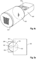
- Fig. 4a shows a side view of a carriage 400 as an exemplary means of transport.
- the carriage 400 comprises a receiving unit 402 in the form of a recess into which a capsule 100 can be inserted by a user (similar to a CD in an extended CD drive).
- the carriage 400 may be driven into the interior of the system 200 by an actuator 401 (eg, by an electrically driven gear), for example in response to a user input, in order to convey the capsule 100 to the processing position 232.
- Fig. 4b shows the carriage 400 in a retracted state.
- the front of the carriage 400 may include a lighting area 403 (as, inter alia, in FIG Fig. 4c shown), which can be illuminated in different colors if necessary.
- a status of the system 200 can be communicated to a user, for example, via the lighting area 403.
- information relating to the beverage produced can be displayed to the user (for example by a specific color coding).
- the front of the carriage 400 may also have a cover area 404, which may be used for the detection of an input by a user (for example, by touching).
- the carriage 400 can be moved out of the system 200 and releases a loading option (i.e. a receiving unit 402) for a beverage capsule 100.
- a loading option i.e. a receiving unit 402
- a user can insert a capsule 100 into the receiving unit 402, and the conveying carriage 400 can then be inserted into the system 200 equipped with the capsule 100 and the beverage production process can then be started.
- the transport carriage 400 can be designed to be energized overall.
- a power supply can be provided on the carriage 400 (e.g. for a reading system for recognizing a capsule type, for the illuminated area 403 and / or for input means on the front of the carriage 400).
- a reading system or a reading sensor can be arranged on the underside of the transport carriage 400 (in particular on the underside of the receiving unit 402), which reading system is designed to recognize a capsule 100 after it has been inserted into the system 200.
- the system 200 can determine preparation parameters for the beverage to be produced based on the recognized capsule 100.
- the reading system can e.g. based on NFC technology.
- At least a partial area of the transport carriage 400 can light up in the color of the beverage to be prepared as a visual recognition confirmation.
- a lemonade e.g. with a yellow light
- a lime juice with a green light e.g.
- the color coding can be set flexibly.
- the status of the manufacturing process can be based on light sequences, e.g. pulsating, static or flashing light.
- a further light source can be provided in the system 200, e.g. the beverage stage (or the dispensing area 233) illuminates.
- the lighting of the output area 233 can be adjusted depending on the status of the manufacturing process. The interaction with the system 200 can be improved in this way.
- a transport carriage 400 enables one by the shape Self-explanatory and ergonomic way of inserting the capsule, whereby incorrect operation can be avoided or at least reduced.
- the receiving unit 402 can have a lowered (at least partially) peripheral edge around an inserted capsule 100. This allows the capsule 100 to be removed (e.g. if the manufacturing process is terminated).
- the manufacturing process can be triggered automatically by moving the carriage 400 in. In this way, the number of interaction steps can be minimized.
- the front design of the carriage 400 can be flexible by providing an interchangeable cover area 404.
- different covers or covers can be put on. These covers can consist of different materials and / or have different surface properties.
- Fig. 5a shows a revolver magazine 500 (or a cylinder) as an exemplary means of transport in a plan view.
- the revolver magazine 500 comprises at least one holding unit 502, which is arranged in a certain position of the revolver magazine 500 outside the system 200, so that a user can insert a capsule 100 into the holding unit 502.
- the revolver magazine 500 can then be rotated about a rotation axis 503 (also referred to as a height axis) (for example in response to an input from a user) in order to convey the receiving unit 502 with the capsule 100 into the interior of the system 200 and in particular to the processing position 232 .
- the revolver magazine 500 can be driven by an actuator 501 (in particular by an electric motor).
- the revolver magazine 502 can be protected by a circumferential impact protection 504, for example to prevent the revolver magazine 502 from being pinched.
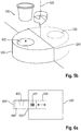
- Fig. 5b shows a perspective view of a revolver magazine 500 (without shock protection 504).
- a capsule 100 can be inserted intuitively and upright, ie the capsule 100 can be inserted with the lid side (on which a label for recognizing the beverage to be produced can be placed) facing upwards, which enables increased comfort for a user becomes.
- the revolver magazine 500 represents a kind of carousel which automatically rotates an inserted capsule 100 into the interior of the system 200.
- a reading system can be located on the underside of the rotating receiving unit 502 (or the case), which can recognize a capsule 100 after insertion, in order to determine corresponding preparation parameters. The process of beverage preparation is carried out inside the system 200.
- the revolver magazine 500 can rotate back into the insertion position to produce another beverage (e.g. if only one receiving unit 502 is provided).
- a further receiving unit 502 can be moved out, into which a next capsule can be accommodated (without further steps). In this way, a convenient and rapid production of several drinks by means of several capsules 100 is made possible.
- the revolver magazine 500 can thus comprise one or more insertion openings or receiving units 502 and the revolver magazine 500 can optionally be rotated in both directions of rotation. Damage to the revolver magazine 500 can be avoided by providing a circumferential impact protection 504 which forms a surface with the revolver magazine 500. Furthermore, by providing a plurality of recording units 502, a plurality of capsules 100 can optionally be picked up by the system 200 at one time (and then processed sequentially). The shape results in a self-explanatory and ergonomic way of inserting the capsule, through which incorrect operation can be avoided or at least reduced. By rotating the revolver magazine 500, the production process of a beverage can be initiated directly, so that the number of interaction steps can be reduced.
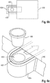
- Fig. 6a (Side view), Fig. 6b (Top view) and Fig. 6c (Perspective view) show a carriage 400 with a circumferential protective bracket 604, by means of which damage to the carriage 400 can be avoided.
- the carriage 400 is arranged within a fixed bracket 604.
- a capsule 100 can be inserted upright (ie with the lid side from above) into the receiving unit 402 of the carriage 400.
- the sled 400 automatically pulls the capsule 100 into the interior of the system 200.
- the capsule 100 can be ejected into a collecting container inside the system 200 and thus release the receiving unit 402 again.
- the carriage 400 can then (possibly automatically) be moved back into the extended insertion position and is thus ready to receive the next capsule 100.
- the provision of a protective bracket 604 enables the carriage 400 to be extended as standard (even in the deactivated state). This can increase the comfort for a user.
- the drive of the carriage 400 can e.g. via a worm gear, a gear transmission, a belt transmission, etc.
- the fixed bracket 604 forms a type of bumper which protects the system 200 (in particular the slide 400) against impacts and other forces.
Landscapes
- Engineering & Computer Science (AREA)
- Food Science & Technology (AREA)
- Mechanical Engineering (AREA)
- Apparatus For Making Beverages (AREA)
Description
- Die Erfindung betrifft ein System zur Herstellung eines individuell portionierten Getränks auf Basis einer Kapsel mit Inhaltsstoffen für ein solches Getränk.
- In professionellen Anwendungen und in Konsumentenanwendungen werden verschiedenste kapselbasierte Getränkesysteme verwendet. Auf Basis des Inhalts von Kapseln können heiße Getränke wie Kaffee oder Tee und kalte Getränke wie Limonaden etc. hergestellt werden. Eine Kapsel enthält dazu meist Inhaltsstoffe (z.B. ein Sirup, ein Pulver, etc.), die in einer separat zuzugebenden Flüssigkeit (insbesondere in Wasser) aufzulösen sind, um das jeweils ausgewählte Getränk herzustellen. Die kapselbasierten Getränkesysteme (in diesem Dokument als Kapselsysteme bezeichnet) bereiten mit Hilfe der Inhaltsstoffe einer Kapsel das jeweilige Getränk portionsweise und nach Bedarf zu.
- Für die Herstellung eines Getränks legt ein Nutzer typischerweise eine Kapsel in das Kapselsystem ein und veranlasst daraufhin, dass die Inhaltsstoffe der Kapsel mit Flüssigkeit vermischt werden, um das Getränk herzustellen. Dabei kann eine Kapsel ggf. falsch eingelegt bzw. verklemmt werden, was zu Problemen bei der Herstellung eines Getränks führen kann. Unterschiedliche Aspekte von Systemen zur Herstellung eines Getränks sind in
WO 2012 / 123 440 A1 ,DE 600 21 531 T1 ,US 9 155 418 B2 DE 601 26 287 T2 ,EP 0 199 953 B1 ,DE 603 09 723 T2 ,US 2008 / 0 203 870 A1 ,DE 10 2008 014 233 B4 ,DE 10 2007 041 093 A1 beschrieben. Des Weiteren beschreibtWO 2006/126230 ein Getränkesystem mit einer Schublade. Ferner beschreibtEP 1 002 490 ein Getränkesystem zur Verarbeitung von Kapseln. - Das vorliegende Dokument befasst sich mit der technischen Aufgabe, ein Kapselsystem zur Herstellung eines Getränks bereitzustellen, das ein zuverlässiges Einführen und Verarbeiten einer Kapsel und somit die zuverlässige Herstellung eines Getränks ermöglicht.
- Die Aufgabe wird durch den Gegenstand des unabhängigen Patentanspruchs gelöst. Vorteilhafte Ausführungsformen sind insbesondere in den abhängigen Patentansprüchen definiert, in nachfolgender Beschreibung beschrieben oder in den Figuren der beigefügten Zeichnung dargestellt.
- Gemäß einem Aspekt der Erfindung wird ein Kapselsystem zur Herstellung eines Getränks beschrieben. Dabei kann von dem Kapselsystem insbesondere eine Kapsel verarbeitet werden, die Inhaltsstoffe für eine Portion (z.B. für ein Glas) eines (alkoholischen oder nicht-alkoholischen) Getränks umfasst. Aus den (insbesondere aus substantiell allen) Inhaltsstoffen einer Kapsel kann durch das Kapselsystem eine Portion eines Getränks hergestellt werden.
- Das Kapselsystem umfasst ein Gehäuse, das zumindest teilweise einen Innenbereich des Kapselsystems umschließt. Beispielsweise kann das Gehäuse quaderförmig sein, mit vier Seitenwänden, einem Boden und einer Deckenwand. Das Kapselsystem kann beispielsweise als ein Hausgerät, insbesondere als ein Haushaltsgerät, ausgebildet sein, das z.B. auf eine Arbeitsplatte einer Küche gestellt und/oder in einen Einbauschrank eingebaut werden kann.
- Außerdem umfasst das Kapselsystem eine Aufnahmeeinheit, die eingerichtet ist, eine Kapsel zur Herstellung eines Getränks aufzunehmen. Insbesondere kann es die Aufnahmeeinheit einem Nutzer ermöglichen, eine Kapsel an das Kapselsystem zu übergeben. An der Aufnahmeeinheit wird dann die Kapsel von dem Kapselsystem aufgenommen, und wird daraufhin typischerweise nicht mehr von einem Nutzer berührt. Ggf. kann die Aufnahmeeinheit Mittel umfassen (z.B. eine Aussparung für einen Finger), die es einem Nutzer ermöglichen, eine bereits an das Kapselsystem übergebene Kapsel wieder zu entfernen (z.B. wenn erkannt wurde, dass eine Kapsel für einen falschen Typ von Getränk eingelegt wurde).
- Das Kapselsystem umfasst weiter Beförderungsmittel, die eingerichtet sind, eine von der Aufnahmeeinheit aufgenommene Kapsel mittels ein oder mehrerer Aktuatoren an eine Verarbeitungsposition im Innenbereich des Kapselsystems zu befördern. Die ein oder mehreren Aktuatoren können z.B. elektrisch betrieben werden. Insbesondere können die ein oder mehreren Aktuatoren ein oder mehrere Elektromotoren umfassen. Durch die Verwendung von automatischen Beförderungsmitteln kann eine zuverlässige und präzise Anordnung einer Kapsel an einer bestimmten Verarbeitungsposition im Innenbereich des Kapselsystems gewährleistet werden.
- Die Kapsel kann an der Verarbeitungsposition geöffnet werden, um aus Inhaltsstoffen der Kapsel ein Getränk herzustellen. Insbesondere kann das Kapselsystem zu diesem Zweck Verarbeitungsmittel umfassen, die eingerichtet sind, eine an der Verarbeitungsposition angeordnete Kapsel zu öffnen, um aus den Inhaltsstoffen der Kapsel ein Getränk herzustellen. Die Verarbeitungsmittel können z.B. ein oder mehrere (Hohl-)Nadeln umfassen, mit denen der Deckel einer Kapsel geöffnet werden kann, um einen Zugang zu den Inhaltsstoffen der Kapsel zu generieren. Die geöffnete Kapsel kann dann ggf. durch eine Flüssigkeit durchspült werden, um ein Getränk aus den Inhaltsstoffen zu erzeugen. Des Weiteren kann das Kapselsystem eine Ausgabeeinheit zur Bereitstellung eines aus einer Kapsel hergestellten Getränks umfassen.
- Das Kapselsystem umfasst außerdem eine Steuereinheit, die eingerichtet ist, den Herstellungsprozess eines Getränks zu steuern. Insbesondere ist die Steuereinheit eingerichtet, die Beförderungsmittel zu veranlassen, eine von der Aufnahmeeinheit aufgenommene erste Kapsel an die Verarbeitungsposition zu befördern. Des Weiteren kann die Steuereinheit eingerichtet sein, zu veranlassen, dass aus den Inhaltsstoffen der ersten Kapsel ein erstes Getränk herstellt wird. Insbesondere kann die Steuereinheit eingerichtet sein, die Verarbeitungsmittel zu veranlassen, aus Inhaltsstoffen der ersten Kapsel ein erstes Getränk herzustellen und über die Ausgabeeinheit bereitzustellen. Dabei kann die Herstellung des ersten Getränks automatisch (d.h. ohne weiteres Einwirken eines Nutzers) durchgeführt werden, sobald sich die erste Kapsel an der Verarbeitungsposition im Innenbereich des Kapselsystems befindet.
- Das Kapselsystem ermöglicht eine komfortable und zuverlässige Herstellung eines Getränks auf Basis der Inhaltsstoffe einer Kapsel. Dabei wird insbesondere durch die Verwendung von angetriebenen Beförderungsmitteln erreicht, dass eine Kapsel zuverlässig und präzise an eine bestimmte Verarbeitungsposition im Kapselsystem befördert wird, so dass Probleme im Herstellungsprozess (wie z.B. eine falsche Platzierung einer Kapsel) vermieden werden können. Die Verwendung von angetriebenen Beförderungsmitteln ist insbesondere bei der Verwendung von Mehrkammer-Kapseln (mit mehreren Kammern für unterschiedliche Substanzen zur Herstellung eines Getränks) vorteilhaft, da das Öffnen und Spülen von derartigen Mehrkammer-Kapseln typischerweise eine besonders präzise Positionierung der Kapsel an einer bestimmten Verarbeitungsposition erfordert.
- Das Kapselsystem kann somit eingerichtet sein, ein Getränk auf Basis einer Mehrkammer-Kapsel herzustellen, die mehrere Kammern mit unterschiedlichen Substanzen zur Herstellung eines Getränks umfasst, wodurch die zuverlässige Herstellung von komplexen Getränken ermöglicht wird.
- Die Mehrkammer-Kapsel kann eine äußere Schale umfassen, die einen äußeren Boden, eine äußere Seitenwand und einen äußeren Deckel aufweist, die einen Gesamthohlraum der Mehrkammer-Kapsel bilden. Außerdem kann die Mehrkammer-Kapsel mindestens eine innere Schale umfassen, die innerhalb des Gesamthohlraums der Kapsel angeordnet ist und die eine zweite Kammer zur Aufnahme eines zweiten Volumens eines zweiten Inhaltsstoffes bildet. Dabei wird durch den Gesamthohlraum abzüglich der mindestens einen inneren Schale ein verbleibender Hohlraum der Mehrkammer-Kapsel als erste Kammer zur Aufnahme eines ersten Volumens eines ersten Inhaltsstoffes gebildet. Die Verarbeitungsmittel können eingerichtet sein, um die innere Schale der Kapsel zu öffnen und um innerhalb der Kapsel einen Hohlraum zur Aufnahme einer Mischung zu schaffen, die den ersten Inhaltsstoff und den zweiten Inhaltsstoff vollständig umfasst. Durch die Herstellung einer Inhaltsstoff-Mischung innerhalb einer Mehrkammer-Kapsel können in zuverlässiger Weise komplexe Getränke hergestellt werden.
- Die Verarbeitungsmittel können eingerichtet sein, die Kapsel zu kippen, um die Inhaltsstoffe, insbesondere um die Inhaltsstoff-Mischung durch eine Öffnung im äußeren Deckel aus der Kapsel zu gießen. So wird eine effiziente Herstellung eines Getränks ermöglicht.
- Die Aufnahmeeinheit kann eine Form aufweisen, die an eine Form der Kapsel angepasst ist, so dass eine Kapsel in zuverlässiger Weise übergeben werden kann. Insbesondere kann eine Aussparung der Aufnahmeeinheit zur Aufnahme einer Kapsel eine Kontur aufweisen, die einer Kontur bzw. einem Umriss der Kapsel entspricht. Dabei kann eine Kapsel z.B. zylinderförmig sein mit unterschiedlich großen Boden- und Deckelflächen. Die Aufnahmeeinheit kann eine Öffnung bzw. Aussparung umfassen, die an die unterschiedlich großen Boden- und Deckelflächen der Kapsel angepasst ist. So kann bewirkt werden, dass ein Nutzer eine Kapsel in intuitiver Weise mit einer korrekten Orientierung an das Kapselsystem übergibt.
- Die Aufnahmeeinheit kann z.B. an einer Frontwand des Gehäuses angeordnet sein. Eine Anordnung an der Frontwand ermöglicht es einem Nutzer eine Kapsel in einer relativ niedrigen Höhe an das Kapselsystem übergeben zu können. Beispielsweise kann das Kapselsystem als ein Hausgerät auf einer Arbeitsplatte einer Küche angeordnet sein, so dass eine an der Frontwand des Kapselsystems angeordnete Aufnahmeeinheit eine komfortable, ergonomisch optimale Kapselübergabe ermöglicht.
- Alternativ oder ergänzend kann die Aufnahmeeinheit derart ausgebildet sein, dass eine Kapsel mit einem nach Oben orientierten Deckel in die Aufnahmeeinheit eingebracht werden kann. Der Deckel der Kapsel kann dabei eine größere Fläche aufweisen als der Boden der Kapsel und die Aufnahmeeinheit kann eine entsprechende Form aufweisen. Durch den Deckel der Kapsel wird typischerweise angezeigt, welcher Typ von Getränk mit der Kapsel hergestellt werden kann (z.B. durch eine bestimmte Farbe und/oder durch einen aufgedruckten Schriftzug). Durch das Übergeben einer Kapsel mit nach Oben orientiertem Deckel kann somit das Einlegen von falschen Kapseln vermieden werden.
- Alternativ oder ergänzend kann die Aufnahmeeinheit derart ausgebildet sein, dass die Kapsel (ggf. auch) in umgekehrter Position, also mit der Kapseloberseite nach unten orientiert in die Aufnahmeeinheit (insbesondere in eine Kapselaufnahme) eingelegt werden kann. Alternativ oder ergänzend kann die Aufnahmeeinheit derart ausgebildet sein, dass die Kapsel (ggf. auch) in waagrechter Position (90° gedreht) in die Aufnahmeeinheit (insbesondere in eine Kapselaufnahme) eingelegt werden kann, mit der Oberseite dem System bzw. dem Gehäuse zugewendet. Alternativ oder ergänzend kann die Aufnahmeeinheit derart ausgebildet sein, dass die Kapsel (ggf. auch) in waagrechter (90° gedreht) Position in die Aufnahmeeinheit (insbesondere in eine Kapselaufnahme) eingelegt werden kann, mit der Oberseite dem Nutzer zugewendet bzw. vom System / Gehäuse weggewendet.
- Die Beförderungsmittel umfassen bevorzugt einen Beförderungsschlitten, der durch die ein oder mehreren Aktuatoren von einem ausgefahrenen Zustand in einen eingefahrenen Zustand überführt werden kann. Insbesondere kann sich der Beförderungsschlitten für die Aufnahme einer Kapsel im ausgefahrenen Zustand befinden, um einem Nutzer eine komfortable Übergabe der Kapsel zu ermöglichen. Dabei kann die Aufnahmeeinheit an dem Beförderungsschlitten angeordnet sein, so dass sich die Aufnahmeeinheit im ausgefahrenen Zustand außerhalb des Gehäuses des Kapselsystems befindet, und somit eine komfortable Übergabe der Kapsel ermöglicht. Andererseits kann sich die Aufnahmeeinheit im eingefahrenen Zustand an der Verarbeitungsposition befinden, um aus den Inhaltsstoffen einer Kapsel ein Getränk herzustellen. Beispielsweise kann der Beförderungsschlitten eine Aussparung aufweisen, in die eine Kapsel eingelegt werden kann (wenn sich der Beförderungsschlitten im ausgefahrenen Zustand befindet). Die Aussparung kann zu diesem Zweck eine einer Kapsel entsprechende Form aufweisen. Die Aufnahmeeinheit kann somit eine Aussparung im Beförderungsschlitten umfassen bzw. einer solchen Aussparung entsprechen. Die Steuereinheit kann eingerichtet sein, den Beförderungsschlitten zu veranlassen, in den ausgefahrenen Zustand zu fahren, um es einem Nutzer zu ermöglichen die erste Kapsel an die Aufnahmeeinheit zu übergeben. Das Ausfahren des Beförderungsschlittens kann in Reaktion auf eine Eingabe eines Nutzers über eine Benutzerschnittstelle des Kapselsystems erfolgen. Des Weiteren kann die Steuereinheit eingerichtet sein, den Beförderungsschlitten zu veranlassen, in den eingefahrenen Zustand zu fahren, um die erste Kapsel an die Verarbeitungsposition zu befördern. Die Verwendung eines Beförderungsmittels ermöglicht eine besonders komfortable und zuverlässige Überführung einer Kapsel von einem Außenbereich des Kapselsystems an die Verarbeitungsposition im Innenbereich des Kapselsystems.
- Der Beförderungsschlitten kann einen Leuchtbereich aufweisen, der eine Mehrzahl von Leuchtzuständen aufweist. Die Leuchtzustände können sich z.B. in Bezug auf Farbe, Lichtintensität und/oder zeitliche Veränderungen von Farbe und/oder Intensität unterscheiden. Die Steuereinheit kann eingerichtet sein, den Leuchtbereich anzusteuern, um mittels der Mehrzahl von Leuchtzuständen, Information in Bezug auf die Herstellung des ersten Getränks auszugeben. Dabei kann die Information in Bezug auf die Herstellung des ersten Getränks insbesondere umfassen: einen Prozessstatus bei der Herstellung des ersten Getränks und/oder einen Typ des hergestellten ersten Getränks. Durch die Bereitstellung eines derartigen Leuchtbereichs kann die Interaktion des Kapselsystems mit einem Nutzer verbessert werden.
- Alternativ oder ergänzend kann der Beförderungsschlitten einen austauschbaren Front-Bereich aufweisen. Dabei kann der Front-Bereich ausgelegt sein, um eine Nutzereingabe zu ermöglichen (z.B. durch Bereitstellung einer Eingabetaste). Insbesondere kann der Front-Bereich ausgelegt sein, um es einem Nutzer zu ermöglichen, durch Berührung des Front-Bereichs das Einfahren des Beförderungsschlittens und ggf. direkt die Herstellung eines Getränks zu veranlassen. Die Bereitstellung eines Front-Bereichs ermöglicht somit eine verbesserte Nutzer-Interaktion.
- Das Kapselsystem kann einen Drucksensor umfassen, der eingerichtet ist, im ausgefahrenen Zustand eine äußere Kraft auf den Beförderungsschlitten zu detektieren, die in Richtung des eingefahrenen Zustands des Beförderungsschlittens wirkt. Beispielsweise kann detektiert werden, dass ein Nutzer mit einer bestimmten äußeren Kraft auf den Beförderungsschlitten drückt. Die Steuereinheit kann eingerichtet sein, zu veranlassen, dass in Reaktion auf das Detektieren der äußeren Kraft der Beförderungsschlitten in den eingefahrenen Zustand überführt wird. So kann eine intuitive Aktivierung der Beförderungsmittel bereitgestellt werden.
- Das Kapselsystem kann einen Schutzbügel umfassen, der ausgebildet ist, um den Beförderungsschlitten im ausgefahrenen Zustand zu umschließen. So können das Kapselsystem und insbesondere der Beförderungsschlitten zuverlässige vor äußeren Einwirkungen geschützt werden.
- Alternativ oder ergänzend können die Beförderungsmittel ein oder mehrere Beförderungsbänder, Beförderungsrollen und/oder Beförderungswalzen umfassen, die durch die ein oder mehreren Aktuatoren angetrieben werden. Die Beförderungsmittel können dabei ausgelegt sein, um eine Kapsel zu berühren und um durch eine Bewegung der ein oder mehreren Beförderungsbänder, Beförderungsrollen und/oder Beförderungswalzen die Kapsel an die Verarbeitungsposition zu befördern. So kann eine zuverlässige Beförderung einer Kapsel in den Innenbereich des Kapselsystems gewährleistet werden.
- Alternativ oder ergänzend können die Beförderungsmittel einen drehbar gelagerten Zylinder (insbesondere einen Kreiszylinder) umfassen, der mittels der ein oder mehreren Aktuatoren um eine Höhenachse des Zylinders gedreht werden kann, so dass eine Grundfläche des Zylinders stets teilweise im Innenbereich und teilweise außerhalb des Gehäuses angeordnet ist. Der drehbar gelagerte Zylinder wird in diesem Dokument auch als Revolvermagazin bezeichnet. Die Höhenachse des Zylinders kann dabei substantiell senkrecht zwischen dem Boden und der Deckenwand des Gehäuses des Kapselsystems verlaufen. Des Weiteren kann die Höhenachse entlang der Frontwand des Gehäuses des Kapselsystems verlaufen.
- Die Aufnahmeeinheit kann durch eine erste Aussparung an der Grundfläche des Zylinders gebildet werden, die derart angeordnet ist, dass die erste Aussparung durch eine Drehung des Zylinders von einem ersten Zustand außerhalb des Gehäuses in einen zweiten Zustand an der Verarbeitungsposition bewegt werden kann. Zu diesem Zweck kann die erste Aussparung mit einem bestimmten Abstand zu der Höhenachse angeordnet sein. Insbesondere kann sich die erste Aussparung näher an einem Rand der Grundfläche des Zylinders als an der Höhenachse des Zylinders befinden. Die Steuereinheit kann eingerichtet sein, die ein oder mehreren Aktuatoren zu veranlassen, den Zylinder um die Höhenachse zu drehen, um die von der Aufnahmeeinheit aufgenommene erste Kapsel an die Verarbeitungsposition zu befördern. Die Verwendung eines drehbar gelagerten Zylinders ermöglicht eine komfortable und präzise Überführung einer Kapsel in den Innenbereich des Kapselsystems.
- Das Kapselsystem kann einen umlaufenden Stoßschutz umfassen, der eine Mantelfläche des Zylinders außerhalb des Gehäuses zumindest teilweise umschließt. So kann das Kapselsystem vor äußeren Krafteinwirkungen geschützt werden.
- Der Zylinder kann eine zweite Aussparung an der Grundfläche des Zylinders aufweisen, die zur Aufnahme einer weiteren Kapsel ausgebildet ist. Die erste Aussparung kann an einer ersten Position auf der Grundfläche und die zweite Aussparung kann an einer Position auf der Grundfläche angeordnet sein, wobei die erste Position und die zweite Position durch eine Gerade miteinander verbunden werden können, die die Höhenachse des Zylinders schneidet (und typischerweise senkrecht zur Höhenachse verläuft). Dabei können die erste Position und die zweite Position auf unterschiedlichen Seiten von der Höhenachse auf der Geraden angeordnet sein. Insbesondere können die erste und die zweite Aussparung derart an der Grundfläche angeordnet sein, dass sich im ersten Zustand die erste Aussparung außerhalb des Gehäuses und die zweite Aussparung an der Verarbeitungsposition und im zweiten Zustand die zweite Aussparung außerhalb des Gehäuses und die erste Aussparung an der Verarbeitungsposition befinden. Durch die Bereitstellung von mehreren Aussparungen als Aufnahmeeinheiten kann die sequentielle Herstellung von mehreren Getränken beschleunigt werden.
- Das Kapselsystem kann einen Sensor umfassen, der eingerichtet ist, zu erkennen, dass die erste Kapsel über die Aufnahmeeinheit an das Kapselsystem übergeben wird. Die Steuereinheit kann eingerichtet sein, in Reaktion darauf, die Beförderungsmittel zu veranlassen, die erste Kapsel an die Verarbeitungsposition zu befördern. Insbesondere kann ohne eine dedizierte Eingabe eines Nutzers bewirkt werden, dass die erste Kapsel nach Übergabe an der Aufnahmeeinheit in den Innenbereich befördert wird. Des Weiteren kann ggf. automatisch (d.h. ohne weitere Eingabe durch einen Nutzer) die Herstellung des ersten Getränks veranlasst werden. So kann die Herstellung eines Getränks in besonders komfortabler Weise veranlasst werden (insbesondere ohne explizite Eingabe durch einen Nutzer des Kapselsystems, ggf. allein in Reaktion auf das Übergeben einer Kapsel an das Kapselsystem an der Aufnahmeeinheit).
- Das Kapselsystem kann einen Lesesensor umfassen, der eingerichtet ist, Information in Bezug auf eine von der Aufnahmeeinheit aufgenommene Kapsel zu erfassen. Der Lesesensor kann z.B. einen RFID-Leser, einen NFC-Leser und/oder einen Leser für einen maschinenlesbaren Code (z.B. einen QR-Code) umfassen. Die Kapsel kann einen entsprechenden Datenträger (z.B. einen RFID-Chip, einen NFC-Chip und/oder einen maschinenlesbaren Code) umfassen. Die Steuereinheit kann eingerichtet sein, das erste Getränk in Abhängigkeit von der erfassten Information in Bezug auf die erste Kapsel herzustellen. Insbesondere kann die Steuereinheit auf Basis der erfassten Information die Menge von ein oder mehreren Zutaten (z.B. Wasser) und/oder ein oder mehrere Prozessschritte zur Herstellung des ersten Getränks ermitteln. So wäre das Kapselsystem befähigt, in komfortabler und zuverlässiger Weise unterschiedliche Typen von Getränken herzustellen.
- Das Kapselsystem kann eine Benutzerschnittstelle umfassen, mit der ein Nutzer z.B. veranlassen kann, dass die Beförderungsmittel eine Kapsel an die Verarbeitungsposition befördern. Alternativ oder ergänzend kann ein Nutzer über die Benutzerschnittstelle ein oder mehrere Parameter eines herzustellenden Getränks festlegen.
- Das Kapselsystem kann weiter (ggf. elektrisch) angetriebene Mittel umfassen, die eine Kapsel nach Entnahme der Inhaltsstoffe aus der Kapsel von der Verarbeitungsposition wegbefördern, um die Verarbeitungsposition für die Aufnahme einer folgenden Kapsel freizugeben. Insbesondere kann eine entleerte Kapsel in einen dafür vorgesehenen Auffangbehälter des Kapselsystems befördert werden.
- Es ist zu beachten, dass jegliche Aspekte des in diesem Dokument beschriebenen Systems in vielfältiger Weise miteinander kombiniert werden können. Insbesondere können die Merkmale der Patentansprüche in vielfältiger Weise miteinander kombiniert werden.
- Im Weiteren wird die Erfindung anhand von in den Figuren der beigefügten Zeichnung dargestellten Ausführungsbeispielen näher beschrieben. Dabei zeigen:
- Figur 1a
- eine beispielhafte Mehrkammer-Kapsel im verschlossenen Zustand;
- Figur 1b
- eine beispielhafte Mehrkammer-Kapsel im geöffneten Zustand;
- Figur 1c
- das beispielhafte Entleeren einer Mehrkammer-Kapsel;
- Figur 2a
- ein Blockdiagramm eines beispielhaften Kapselsystems zur Herstellung eines Getränks;
- Figur 2b
- eine perspektivische Ansicht eines Kapselsystems zur Herstellung eines Getränks;
- Figur 3a
- eine perspektivische Ansicht von beispielhaften Beförderungsbändern zur Beförderung einer Kapsel an eine Verarbeitungsposition;
- Figur 3b
- eine seitliche Ansicht eines beispielhaften Beförderungsbandes zur Beförderung einer Kapsel an eine Verarbeitungsposition;
- Figur 3c
- eine beispielhafte Aufnahmeeinheit zur Aufnahme einer Kapsel;
- Figur 4a
- eine Seitenansicht eines beispielhaften Beförderungsschlittens für eine Kapsel im ausgefahrenen Zustand;
- Figur 4b
- eine Seitenansicht eines beispielhaften Beförderungsschlittens für eine Kapsel im eingefahrenen Zustand;
- Figur 4c
- eine perspektivische Ansicht eines beispielhaften Beförderungsschlittens;
- Figur 5a
- eine Draufsicht eines beispielhaften Revolvermagazins zur Aufnahme und zur Beförderung einer Kapsel;
- Figur 5b
- eine perspektivische Ansicht eines beispielhaften Revolvermagazins;
- Figur 6a
- eine Seitenansicht eines beispielhaften Beförderungsschlittens mit Schutzrahmen;
- Figur 6b
- eine Draufsicht eines beispielhaften Beförderungsschlittens mit Schutzrahmen; und
- Figur 6c
- eine perspektivische Ansicht eines beispielhaften Beförderungsschlittens mit Schutzrahmen.
- Wie eingangs dargelegt, befasst sich das vorliegende Dokument mit der zuverlässigen Herstellung eines Getränks auf Basis der Inhaltsstoffe einer Kapsel.
- In diesem Zusammenhang zeigt
Fig. 1a eine beispielhafte Kapsel, insbesondere eine beispielhafte Mehrkammer-Kapsel 100. Die inFig. 1a dargestellte Kapsel 100 umfasst zwei Kammern 110, 120, wobei die Kammern 110, 120 durch separate Schalen gebildet werden, die ineinander verschachtelt sind. Eine äußere Schale wird durch eine äußere Seitenwand 102 und einen äußeren Boden 103 gebildet, die einen Gesamthohlraum der Kapsel 100 umschließen. In dem Gesamthohlraum ist eine innere Schale angeordnet, die durch eine innere Seitenwand 122 und einen inneren Boden 123 gebildet wird. In dem dargestellten Beispiel werden die innere Schale und die äußere Schale durch einen gemeinsamen Deckel 104 abgeschlossen. - Die innere Schale bildet die zweite Kammer 120 zur Aufnahme eines zweiten Inhaltsstoffes 121. Ggf. können innerhalb der äußeren Schale, d.h. innerhalb des Gesamthohlraums der Kapsel 100, mehrere innere Schalen angeordnet sein, die mehrere separate Kammern 120 zur Aufnahme von unterschiedlichen Inhaltsstoffen bzw. Substanzen bilden. Der Gesamthohlraum abzüglich der ein oder mehreren inneren Schalen bildet einen verbleibenden Hohlraum, der die erste Kammer 110 zur Aufnahme eines ersten Inhaltsstoffes 111 bildet. Die Inhaltsstoffe 111, 121 (die in diesem Dokument auch als Substanzen bezeichnet werden) können flüssig und/oder fest (z.B. pulverförmig) sein bzw. flüssige und/oder feste (z.B. pulverförmige) Bestandteile umfassen. Jede Kammer 110, 120 der Kapsel 100 kann ein bestimmtes Volumen eines Inhaltsstoffes umfassen. Diese Volumina an unterschiedlichen Inhaltsstoffen werden substantiell vollständig für die Herstellung eines Getränks verwendet. Des Weiteren können die Kammern 110, 120 ggf. Gase (z.B. Luft oder Inertgas) umfassen, die nicht für die Herstellung verwendet werden.
- Die Mehrkammer-Kapsel 100 kann derart ausgebildet sein, dass im Rahmen der Herstellung eines Getränks ein Hohlraum innerhalb der Mehrkammer-Kapsel 100 zur Aufnahme einer Inhaltsstoff-Mischung 101 geschaffen werden kann, die den ersten Inhaltsstoff 111 und den zweiten Inhaltsstoff 121 (substantiell vollständig) umfasst. Mit anderen Worten, die Mehrkammer-Kapsel 100 kann derart ausgebildet sein, dass innerhalb der Mehrkammer-Kapsel 100 (z.B. innerhalb der ersten Kammer 110) eine Inhaltsstoff-Mischung 101 hergestellt werden kann, die die gesamten, für das Getränk bestimmten, Inhaltsstoffe 111, 121 der Kapsel 100 umfasst (z.B. in Form einer Lösung und/oder Emulsion). So kann eine zuverlässig wiederholbare Herstellung eines Getränks aus Mehrkammer-Kapseln 100 bewirkt werden.
-
Fig. 1a zeigt eine Mehrkammer-Kapsel 100 in verschlossenem Zustand. Das Kapselsystem kann Mittel umfassen (z.B. ein oder mehrere Nadeln), um ein oder mehrere Kammern 110, 120 einer Kapsel 100 zu öffnen, und um die Inhaltsstoffe 111, 121 der Kammern 110, 120 miteinander zu vermischen. Beispielsweise kann, wie inFig. 1b dargestellt, eine Öffnung 125 im inneren Boden 123 der inneren Schale bewirkt werden, so dass der zweite Inhaltsstoff 121 (vollständig) aus der zweiten Kammer 120 in die erste Kammer 110 gelangen kann und sich innerhalb der ersten Kammer 110 mit dem ersten Inhaltsstoff 111 vermischen kann, um eine Inhaltsstoff-Mischung 101 zu erzeugen. Die Inhaltsstoff-Mischung 101 kann dann über ein oder mehrere weitere Öffnungen (z.B. im äußeren Deckel 104, im äußeren Boden 103 und/oder in der äußeren Seitenwand 102) aus der Kapsel 100 entnommen werden (wie durch die Pfeile dargestellt). Beispielsweise kann die Kapsel 100 gekippt werden (wie inFig. 1c dargestellt), um die Inhaltsstoff-Mischung 101 durch eine Öffnung im äußeren Deckel 104 durch Einwirken der Schwerkraft aus der Kapsel 100 zu gießen. - Das Kapselsystem kann somit z.B. eine Nadel zum Anstechen einer Kapsel 100 sowie Mittel zum Vermischen und/oder Auflösen der Substanzen 111, 121 (ggf. mit einer oder mehreren Flüssigkeiten wie z.B. Wasser oder Alkohol bzw. mit Wasserdampf) umfassen. Des Weiteren kann das Kapselsystem Mittel umfassen, um die dabei entstandene Inhaltsstoff-Mischung 101 zu Entleeren und ggf. mit einer weiteren Flüssigkeit zu vermischen oder direkt in ein Glas zu überführen, um ein Getränk bereitzustellen. Die
Figuren 1a bis 1c zeigen beispielhafte eine Zweikammer-Kapsel. Es können aber innerhalb des Gesamthohlraums einer Kapsel 100 auch mehr als zwei Kammern 110, 120 oder ggf. nur eine Kammer bereitgestellt werden. - Wie in
Fig. 1b dargestellt können die ein oder mehreren (inneren) Schalen bzw. Kammern 120 geöffnet werden, um die Substanzen 111, 121 einer Kapsel 100 miteinander zu vermischen. Dabei können ausschließlich die in den Kammern 110, 120 enthaltenen Substanzen 111, 121 miteinander vermischt werden. Alternativ können ein oder mehrere weitere Medien (z.B. in flüssiger und/oder gasförmiger Form) von außen in die Kapsel 100 zugeführt werden, um die Substanzen 111, 121 der Kammern 110, 120 miteinander zu vermischen. Die in der Kapsel 100 hergestellte Mischung 101 kann somit neben den Inhaltsstoffen 111, 121 noch ein oder mehrere weitere Medien (insbesondere Spül-Medien) umfassen. Die Kapsel 100 ist dabei bevorzugt derart ausgelegt, dass auch diese Medien aufgenommen werden können. Zur Herstellung der Mischung 101 kann mindestens eine Kammer 120 restlos entleert und bei Bedarf mittels eines Spül-Mediums gespült werden. Die so hergestellte Mischung 101 (z.B. eine Lösung und/oder Emulsion) kann dann dem weiteren Getränkezubereitungsprozess (außerhalb der Kapsel 100) über verschiedene Umsetzungsarten zugeführt werden. -
Fig. 2a zeigt ein Blockdiagramm eines beispielhaften Kapselsystems 200. Das Kapselsystem 200 umfasst eine Steuereinheit 201, die eingerichtet ist, den Herstellungsprozess eines Getränks zu steuern. Durch einen Nutzer kann eine Kapsel 100 an das System 200 übergeben werden (in eine dafür vorgesehene Kapsel-Aufnahmeeinheit des Systems 200). Die Kapsel kann dann über Beförderungsmittel an eine Verarbeitungsposition 232 im Inneren eines Gehäuses des Kapselsystems 200 überführt werden. Die Beförderungsmittel können durch den Nutzer (z.B. durch Betätigen eines Knopfes oder direkt durch Einführen der Kapsel 100) aktiviert werden. Bei Ankunft der Kapsel 100 an der Verarbeitungsposition 232 kann dann der Herstellungsprozess angestoßen werden. - Die Steuereinheit 201 bewirkt im Rahmen des Herstellungsprozesses, dass die Mittel 221, 220 zum Öffnen der Kapsel 100 (z.B. (hohle) Nadeln) an die Kapsel 100 geführt werden. Dazu kann ein Aktuator 204 angesteuert werden, der z.B. die Nadeln 221, 220 in die Kapsel 100 einführt. Des Weiteren kann ein weiterer Aktuator 203 angesteuert werden, um ein Spül-Medium (z.B. aus einem Behälter 202 des Systems 200) in die Kapsel 100 zu drücken, um zumindest eine Kammer 120 in der Kapsel 100 zu spülen. So kann ggf. in einem ersten Schritt eine Mischung 101 der Inhaltsstoffe 111, 121 aus unterschiedlichen Kammern 110, 120 einer Kapsel 100 erzeugt werden. Die Mischung 101 kann dann aus der Kapsel 100 entnommen werden. Beispielsweise kann das System 200 einen Kipp-Mechanismus 205 aufweisen, der eingerichtet ist, die Kapsel 100 zu kippen, so dass die Mischung 101 (z.B. durch die Öffnung 105 im äußeren Deckel 104) aus der Kapsel 100 gegossen werden kann. Insbesondere kann die Mischung 101 über eine Ausgabeeinheit 206 des Systems 200 in einen Becher 210 gegossen werden, in dem das zu erstellende Getränk dem Nutzer bereitgestellt wird. Das System 200 kann außerdem eingerichtet sein, weitere ein oder mehrere Flüssigkeiten für das zu erstellende Getränk in den Becher 210 zu füllen.
-
Fig. 2b zeigt eine perspektivische Ansicht von Teilen des Kapselsystems 200. Das Kapselsystem 200 umfasst typischerweise ein Gehäuse mit einer Mehrzahl von Gehäusewänden, die zumindest teilweise einen Innenbereich des Kapselsystems 200 umschließen. An einer Wand 240 (insbesondere an einer Frontwand) des Kapselsystems 200 kann eine Öffnung 230 angeordnet sein, von der eine Kapsel 100 über einen Beförderungsweg 231 zu der Verarbeitungsposition 232 im Innenbereich des Gehäuses befördert werden kann. An der Verarbeitungsposition 232 kann die Kapsel 100 geöffnet und entleert werden, um ein Getränk herzustellen. Das Getränk kann dann in einem Ausgabebereich 233 über eine Ausgabeeinheit 206 ausgegeben werden.Fig. 2b zeigt weiter eine Benutzerschnittstelle 234 (z.B. mit einem berührungsempfindlichen Bildschirm), über die ein Nutzer Einstellung des Kapselsystems 200 vornehmen kann. Die Benutzerschnittstelle 234 kann, wie inFig. 2b dargestellt, an einer oberen Gehäusewand des Kapselsystems 200 angeordnet sein. Das Kapselsystem 200 kann als Hausgerät, insbesondere als Haushaltsgerät, ausgebildet sein, das z.B. auf die Arbeitsplatte einer Küche gestellt werden kann. - Im Folgenden werden beispielhafte Beförderungsmittel beschrieben, mit denen eine Kapsel 100 automatisch von einer Aufnahmeeinheit (die z.B. an oder vor der Frontwand 240 angeordnet ist) zu der Verarbeitungsposition 232 befördert wird. Die Beförderungsmittel umfassen dazu ein oder mehrere Aktuatoren, durch die eine Bewegung einer Kapsel 100 zur Verarbeitungsposition 232 bewirkt werden kann. Durch die automatische Beförderung einer Kapsel 100 mittels angetriebener Beförderungsmittel an eine definierte Verarbeitungsposition 232 können Fehlplatzierungen und/oder Einklemmsituationen von Kapseln 100 vermieden werden, so dass eine zuverlässige Herstellung von Getränken ermöglicht wird.
- In
Fig. 3a ist als Beispiel für ein Beförderungsmittel ein Beförderungsband 300 dargestellt, das durch ein oder mehrere Aktuatoren (z.B. Elektromotoren) 301 bewegt wird und das eingerichtet ist, eine Kapsel 100 von einer Aufnahmeeinheit 302 an der Öffnung 230 der Gehäusewand 240 zu der Verarbeitungsposition 232 im Innenbereich des Gehäuses zu befördern. Das Beförderungsband 300 kann z.B. durch elektrisch angetriebene Walzen bewegt werden.Fig. 3b zeigt das Beförderungsband 300 in einer Seitenansicht. Insbesondere ist inFig. 3b veranschaulicht, wie eine Kapsel 100 durch einen Nutzer an der Aufnahmeeinheit 302 an das Kapselsystem 100 übergeben werden kann und dann von dem Beförderungsband 300 automatisch in den Innenbereich des Systems 200 zu der Verarbeitungsposition 232 befördert wird. -
Fig. 3c veranschaulicht, wie ein Nutzer 100 eine Kapsel 100 an der Aufnahmeeinheit 302 an das System 200 übergeben kann. Dabei können an der Aufnahmeeinheit 302 ein oder mehrere Sensoren angeordnet sein, die erkennen, dass eine Kapsel 100 an das System 200 übergeben wird. In Reaktion darauf können dann die Beförderungsmittel 300 (d.h. insbesondere das Beförderungsband) aktiviert werden, um die Kapsel 100 in das Innere des Systems 100 zu befördern. Des Weiteren kann bei Ankunft der Kapsel 100 an der Verarbeitungsposition 232 automatisch der Herstellungsprozess eines Getränks initiiert werden. - An der Front des Getränkesystems 200 kann sich somit ein Eingabeslot 302 (d.h. eine Aufnahmeeinheit) befinden (z.B. vergleichbar mit dem Eingabeslot an einem Geldautomaten). Die Kontur einer Aussparung der Aufnahmeeinheit 302 kann dabei der Kontur einer Kapsel 100 entsprechen, so dass eine definierte Übergabe einer Kapsel 100 an das System 200 ermöglicht wird. Ein, zwei oder mehr Führungsschienen können dazu verwendet werden, eine Kapsel 100 zu arretieren. Eine Kapsel 100 kann in die Aussparung der Aufnahmeeinheit 302 geschoben werden und kann dort von Beförderungsmitteln 300 (z.B. von angetriebenen Rollen oder von einem angetriebenen Bandtransportsystem) aufgenommen werden und weiter ins Innere des Systems 200 gezogen werden. Die Gesamterscheinung des Systems 200 ermöglicht durch die Formgebung der Aufnahmeeinheit 302 eine selbsterklärende und ergonomische Art des Kapsel-Einlegens, wodurch Fehlbedienungen ausgeschlossen oder zumindest reduziert werden können. Des Weiteren ermöglicht eine derartige Aufnahmeeinheit 302 eine Reduzierung von Interaktionsschritten, da durch das Einlegen automatisch die Herstellung eines Getränks initiiert werden kann. Außerdem weist das System 200 eine hohe Robustheit auf, da die Beförderungsmittel 300 vollständig im Inneren des Systems 200 angeordnet sind und somit nicht durch einen Nutzer berührt und ggf. beschädigt werden können.
-
Fig. 4a stellt einen Beförderungsschlitten 400 als beispielhaftes Beförderungsmittel in einer Seitenansicht dar. Der Beförderungsschlitten 400 umfasst eine Aufnahmeeinheit 402 in Form einer Aussparung, in die von einem Nutzer eine Kapsel 100 eingelegt werden kann (ähnlich wie eine CD in ein ausgefahrenes CD-Laufwerk). Der Beförderungsschlitten 400 kann, z.B. in Reaktion auf eine Eingabe eines Nutzers, durch einen Aktuator 401 (z.B. durch ein elektrisch angetriebenes Zahnrad) in das Innere des Systems 200 gefahren werden, um die Kapsel 100 an die Verarbeitungsposition 232 zu befördern.Fig. 4b zeigt den Beförderungsschlitten 400 in einem eingefahrenen Zustand. - Die Frontseite des Beförderungsschlittens 400 kann einen Leuchtbereich 403 umfassen (wie u.a. in
Fig. 4c dargestellt), der ggf. in unterschiedlichen Farben beleuchtet werden kann. Über den Leuchtbereich 403 kann z.B. einem Nutzer ein Zustand des Systems 200 mitgeteilt werden. Alternativ oder ergänzend kann dem Nutzer Information in Bezug auf das hergestellte Getränk angezeigt werden (z.B. durch eine bestimmte Farbkodierung). Die Frontseite des Beförderungsschlittens 400 kann außerdem einen Cover-Bereich 404 aufweisen, der ggf. für die Erfassung einer Eingabe eines Nutzers (z.B. durch eine Berührung) verwendet werden kann. - Ähnlich wie eine CD-Schublade kann der Beförderungsschlitten 400 aus dem System 200 herausgefahren werden, und gibt eine Einlegemöglichkeit (d.h. eine Aufnahmeeinheit 402) für eine Getränkekapsel 100 frei. Ein Nutzer kann eine Kapsel 100 in die Aufnahmeeinheit 402 einlegen, und der Beförderungsschlitten 400 kann dann bestückt mit der Kapsel 100 in das System 200 eingefahren werden und es kann daraufhin der Herstellungsprozess für ein Getränk gestartet werden.
- Bei einem geschlossenen Beförderungsschlitten 400 wird das System 200 somit gegenüber Umwelt-/Fremdeinflüssen abgeschlossen bzw. geschützt. Das Öffnen und Schließen des Beförderungsschlittens 400 erfolgt automatisch/motorisch über ein oder mehrere Aktuatoren 401. Auslöser für die Einfahrbewegung können insbesondere folgende Elemente oder Interaktionen sein:
- die Betätigung eines dedizierten Eingabebereichs (z.B. Taste, Knopf, Bildschirmbereich, etc.) am Getränkesystem 200;
- die Frontseite des Beförderungsschlittens 400, die als dedizierter Eingabebereich dient (z.B. über eine Touch-Interaktion oder durch ein leichtes Drücken wie bei einer CD-Schublade (ohne Verwendung eines Sensors an der Frontseite des Beförderungsschlittens 400)); und/oder
- die Betätigung einer Eingabe über eine Benutzerschnittstelle 234 des Systems 200 (z.B. ein darin integrierter (ggf. virtueller) Knopf).
- Der Beförderungsschlitten 400 kann insgesamt bestromt ausgeführt werden. Insbesondere kann an dem Beförderungsschlitten 400 eine Energieversorgung bereitgestellt werden (z.B. für ein Lesesystem zur Erkennung eines Kapsel-Typs, für den Leuchtbereich 403 und/oder für Eingabemittel an der Frontseite des Beförderungsschlittens 400).
- An der Unterseite des Beförderungsschlittens 400 (insbesondere an der Unterseite der Aufnahmeeinheit 402) kann ein Lesesystem bzw. ein Lesesensor angeordnet sein, das bzw. der eingerichtet ist, eine Kapsel 100 nach dem Einlegen in das System 200 zu erkennen. Das System 200 kann basierend auf der erkannten Kapsel 100 Zubereitungsparameter für das herzustellende Getränk ermitteln. Das Lesesystem kann z.B. auf NFC-Technologie basieren.
- Durch ein entsprechend gestaltetes integriertes Lichtsystem im Leuchtbereich 403 kann als visuelle Erkennungsbestätigung zumindest ein Teilbereich des Beförderungsschlittens 400 in der Farbe des zuzubereitenden Getränkes leuchten. Beispielsweise kann eine Zitronenlimonade z.B. mit einer gelben Beleuchtung, und ein Limonensaft mit einer grünen Beleuchtung angezeigt werden. Die Farbkodierung kann dabei flexible eingestellt werden. Alternativ oder ergänzend kann der Status des Herstellungsprozesses mit Lichtsequenzen, z.B. pulsierendem, statischem oder blinkendem Licht, angezeigt werden. Optional kann eine weitere Lichtquelle im System 200 bereitgestellt werden, die z.B. die Getränkebühne (bzw. den Ausgabebereich 233) ausleuchtet. Die Beleuchtung des Ausgabebereichs 233 kann in Abhängigkeit von dem Status des Herstellungsprozesses angepasst werden. So kann die Interaktion mit dem System 200 verbessert werden.
- Die Verwendung eines Beförderungsschlittens 400 ermöglicht durch die Formgebung eine selbsterklärende und ergonomische Art des Kapsel-Einlegens, wodurch Fehlbedienungen vermieden oder zumindest reduziert werden können.
- Die Aufnahmeeinheit 402 kann einen abgesenkten (zumindest teilweise) umlaufenden Rand um eine eingelegte Kapsel 100 aufweisen. So kann die Entnahme der Kapsel 100 (z.B. bei einem Abbruch des Herstellungsprozesses) ermöglicht werden.
- Der Herstellungsprozess kann automatisch durch das Einfahren des Beförderungsschlittens 400 ausgelöst werden. So kann die Anzahl von Interaktionsschritten minimiert werden.
- Die Frontgestaltung des Beförderungsschlittens 400 kann durch Bereitstellung eines austauschbaren Cover-Bereichs 404 flexibel sein. Beispielsweise können unterschiedliche Cover oder Abdeckungen aufgesetzt werden. Diese Cover können aus verschiedenen Materialien bestehen und/oder unterschiedliche Oberflächen-Beschaffenheit aufweisen.
-
Fig. 5a zeigt ein Revolvermagazin 500 (bzw. einen Zylinder) als beispielhaftes Beförderungsmittel in einer Draufsicht. Das Revolvermagazin 500 umfasst zumindest eine Aufnahmeeinheit 502, die in einer bestimmten Stellung des Revolvermagazins 500 außerhalb des Systems 200 angeordnet ist, so dass ein Nutzer eine Kapsel 100 in die Aufnahmeeinheit 502 einlegen kann. Das Revolvermagazin 500 kann dann um eine Rotationsachse 503 (auch als Höhenachse bezeichnet) gedreht werden (z.B. in Reaktion auf eine Eingabe eines Nutzers), um die Aufnahmeeinheit 502 mit der Kapsel 100 in das Innere des Systems 200 und insbesondere zu der Verarbeitungsposition 232 zu befördern. Zu diesem Zweck kann das Revolvermagazin 500 durch einen Aktuator 501 (insbesondere durch einen Elektromotor) angetrieben werden. Das Revolvermagazin 502 kann durch einen umlaufenden Stoßschutz 504 geschützt sein, um z.B. ein Einklemmen des Revolvermagazins 502 zu verhindern.Fig. 5b zeigt eine perspektivische Ansicht eines Revolvermagazins 500 (ohne Stoßschutz 504). - In ein derartiges Revolvermagazin 500 kann eine Kapsel 100 intuitiv und aufrecht eingelegt werden, d.h. die Kapsel 100 kann mit der Deckelseite (auf der ein Aufdruck zur Erkennung des herzustellenden Getränks dargestellt sein kann) nach oben eingelegt werden, wodurch ein erhöhter Komfort für einen Nutzer ermöglicht wird.
- Das Revolvermagazin 500 stellt eine Art Karussell dar, welches eine eingelegte Kapsel 100 automatisch ins Innere des Systems 200 rotiert. An der Unterseite der rotierenden Aufnahmeeinheit 502 (bzw. des Futterals) kann sich ein Lesesystem befinden, das eine Kapsel 100 nach dem Einlegen erkennt kann, um entsprechende Zubereitungsparameter zu bestimmen. Im Inneren des Systems 200 wird der Prozess der Getränkezubereitung durchgeführt.
- Das Revolvermagazin 500 kann zur Herstellung eines weiteren Getränks in die Einlegestellung zurückrotieren (z.B. wenn nur eine Aufnahmeeinheit 502 bereitgestellt wird). Alternativ kann durch die Drehbewegung, mit der eine Kapsel in das Innere des Systems 200 rotiert wird, eine weitere Aufnahmeeinheit 502 herausgefahren werden, in die (ohne weitere Schritte) eine nächste Kapsel aufgenommen werden kann. So kann eine komfortable und zügige Herstellung von mehreren Getränken mittels mehrerer Kapseln 100 ermöglicht werden.
- Das Revolvermagazin 500 kann somit eine oder mehrere Einlegeöffnungen bzw. Aufnahmeeinheiten 502 umfassen und die Drehung des Revolvermagazins 500 kann ggf. in beide Drehrichtungen erfolgen. Durch Bereitstellung eines umlaufenden Stoßschutzes 504, der mit dem Revolvermagazin 500 eine Fläche bildet, können Beschädigungen des Revolvermagazins 500 vermieden werden. Des Weiteren können durch Bereitstellen von mehreren Aufnahmeeinheiten 502 ggf. mehrere Kapseln 100 auf einmal von dem System 200 aufgenommen werden (und dann sequentiell verarbeitet werden). Durch die Formgebung ergibt sich eine selbsterklärende und ergonomische Art des Kapsel-Einlegens, durch die Fehlbedienungen vermieden oder zumindest reduziert werden können. Mit dem Rotieren des Revolvermagazins 500 kann direkt der Herstellungsprozess eines Getränks angestoßen werden, so dass die Anzahl von Interaktionsschritten reduziert werden kann.
-
Fig. 6a (Seitenansicht),Fig. 6b (Draufsicht) undFig. 6c (perspektivische Ansicht) zeigen einen Beförderungsschlitten 400 mit einem umlaufenden Schutzbügel 604, durch den eine Beschädigung des Beförderungsschlittens 400 vermieden werden kann. Insbesondere ist in denFiguren 6a ,6b und 6c der Beförderungsschlitten 400 innerhalb eines feststehenden Bügels 604 angeordnet. In die Aufnahmeeinheit 402 des Schlittens 400 kann eine Kapsel 100 aufrecht (d.h. mit der Deckelseite von oben) eingelegt werden. Der Schlitten 400 zieht die Kapsel 100 automatisch ins Innere des Systems 200. Sobald der Prozess der Getränkeerstellung abgeschlossen ist, kann die Kapsel 100 in einen Auffangbehälter im Inneren des Systems 200 ausgeworfen werden, und somit die Aufnahmeeinheit 402 wieder freigeben. Der Schlitten 400 kann dann (ggf. automatisch) wieder zurück in die ausgefahrene Einlegestellung gefahren werden, und ist somit bereit, die nächste Kapsel 100 aufzunehmen. Die Bereitstellung eines Schutzbügels 604 ermöglicht es dabei, dass der Schlitten 400 standardmäßig ausgefahren ist (auch im deaktivierten Zustand). So kann der Komfort für einen Nutzer erhöht werden. - Der Antrieb des Schlittens 400 kann z.B. über ein Schneckengetriebe, ein Zahnradgetriebe, eine Riemenübersetzung, etc. erfolgen.
- Der feststehende Bügel 604 bildet eine Art Stoßstange, die das System 200 (insbesondere den Schlitten 400) gegen Stöße und andere Krafteinwirkungen schützt.
- Die vorliegende Erfindung ist nicht auf die gezeigten Ausführungsbeispiele beschränkt. Insbesondere ist zu beachten, dass die Beschreibung und die Figuren nur das Prinzip des vorgeschlagenen Systems veranschaulichen sollen.
Claims (12)
- Kapselsystem (200) zur Herstellung eines Getränks, wobei das Kapselsystem (200) umfasst:- ein Gehäuse, das zumindest teilweise einen Innenbereich des Kapselsystems (200) umschließt;- eine Aufnahmeeinheit (302, 402, 502), die eingerichtet ist, eine Kapsel (100) zur Herstellung eines Getränks aufzunehmen;- Beförderungsmittel (300, 400, 500), die eingerichtet sind, eine von der Aufnahmeeinheit (302, 402, 502) aufgenommene Kapsel (100) mittels ein oder mehrerer Aktuatoren (301, 401, 501) an eine Verarbeitungsposition (232) im Innenbereich des Kapselsystems (200) zu befördern; wobei die Beförderungsmittel (300, 400, 500) einen Beförderungsschlitten (400) umfassen, der durch die ein oder mehreren Aktuatoren (401) von einem ausgefahrenen Zustand in einen eingefahrenen Zustand überführt werden kann; wobei die Aufnahmeeinheit (402) an dem Beförderungsschlitten (400) angeordnet ist, so dass sich die Aufnahmeeinheit (402) im ausgefahrenen Zustand außerhalb des Gehäuses des Kapselsystems (200) befindet, um eine Kapsel (100) aufzunehmen, und sich im eingefahrenen Zustand an der Verarbeitungsposition (232) befindet;- Verarbeitungsmittel (204), die eingerichtet sind, eine an der Verarbeitungsposition (232) angeordnete Kapsel (100) zu öffnen, um aus Inhaltsstoffen der Kapsel (100) ein Getränk herzustellen;- eine Ausgabeeinheit (206) zur Bereitstellung eines aus einer Kapsel (100) hergestellten Getränks;- einen Sensor, der eingerichtet ist, zu erkennen, dass eine erste Kapsel (100) über die Aufnahmeeinheit (302, 402, 502) durch einen Nutzer an das Kapselsystem (200) übergeben wird; und- eine Steuereinheit (201), die eingerichtet ist,- in Reaktion darauf, dass durch den Sensor erkannt wird, dass die erste Kapsel (100) an das Kapselsystem (200) übergeben wurde, den Beförderungsschlitten (400) automatisch zu veranlassen, von dem ausgefahrenen Zustand in den eingefahrenen Zustand zu fahren, um die erste Kapsel (100) an die Verarbeitungsposition (232) zu befördern; und- im Anschluss daran die Verarbeitungsmittel (204) zu veranlassen, aus Inhaltsstoffen der ersten Kapsel (100) ein erstes Getränk herzustellen und über die Ausgabeeinheit (206) bereitzustellen.
- Kapselsystem (200) gemäß Anspruch 1, wobei- der Beförderungsschlitten (400) einen Leuchtbereich (403) aufweist, der eine Mehrzahl von Leuchtzuständen aufweist;- die Steuereinheit (201) eingerichtet ist, den Leuchtbereich (403) anzusteuern, um mittels der Mehrzahl von Leuchtzuständen, Information in Bezug auf die Herstellung des ersten Getränks auszugeben; und- die Information in Bezug auf die Herstellung des ersten Getränks insbesondere umfasst: einen Prozessstatus bei der Herstellung des ersten Getränks; und/oder einen Typ des hergestellten ersten Getränks.
- Kapselsystem (200) gemäß einem der vorhergehenden Ansprüche, wobei der Beförderungsschlitten (400) einen austauschbaren Front-Bereich (404) aufweist.
- Kapselsystem (200) gemäß einem der vorhergehenden Ansprüche, wobei das Kapselsystem (200) einen Schutzbügel (604) umfasst, der ausgebildet ist, um den Beförderungsschlitten (400) im ausgefahrenen Zustand zu umschließen.
- Kapselsystem (200) gemäß einem der vorhergehenden Ansprüche, wobei- das Kapselsystem (200) einen Drucksensor umfasst, der eingerichtet ist, im ausgefahrenen Zustand eine äußere Kraft auf den Beförderungsschlitten (400) zu detektieren, die in Richtung des eingefahrenen Zustands des Beförderungsschlittens (400) wirkt; und- die Steuereinheit (201) eingerichtet ist, zu veranlassen, dass in Reaktion auf das Detektieren der äußeren Kraft der Beförderungsschlitten (400) in den eingefahrenen Zustand überführt wird.
- Kapselsystem (200) gemäß einem der vorhergehenden Ansprüche, wobei- das Kapselsystem (200) einen Lesesensor umfasst, der eingerichtet ist, Information in Bezug auf eine von der Aufnahmeeinheit (302, 402, 502) aufgenommenen Kapsel (100) zu erfassen; und- die Steuereinheit (201) eingerichtet ist, das erste Getränk in Abhängigkeit von der erfassten Information in Bezug auf die erste Kapsel (100) herzustellen.
- Kapselsystem (200) gemäß einem der vorhergehenden Ansprüche, wobei das Kapselsystem (200) eingerichtet ist, ein Getränk auf Basis einer Kapsel (100) herzustellen, die mehrere Kammern (110, 120) mit unterschiedlichen Substanzen (111, 121) zur Herstellung eines Getränks umfasst.
- Kapselsystem (200) gemäß Anspruch 7, wobei- die Kapsel (100) eine äußere Schale (200) umfasst, die einen äußeren Boden (103), eine äußere Seitenwand (102) und einen äußeren Deckel (104) aufweist, die einen Gesamthohlraum der Kapsel (100) bilden;- die Kapsel (100) mindestens eine innere Schale (220) umfasst, die innerhalb des Gesamthohlraums der Kapsel (100) angeordnet ist und die eine zweite Kammer (120) zur Aufnahme eines zweiten Volumens eines zweiten Inhaltsstoffes (121) bildet; wobei durch den Gesamthohlraum abzüglich der mindestens einen inneren Schale (220) ein verbleibender Hohlraum der Kapsel (100) als erste Kammer (110) zur Aufnahme eines ersten Volumens eines ersten Inhaltsstoffes (111) gebildet wird; und- die Verarbeitungsmittel (204) eingerichtet sind, um die innere Schale (220) der Kapsel (100) zu öffnen und um innerhalb der Kapsel (100) einen Hohlraum zur Aufnahme einer Mischung (101) zu schaffen, die den ersten Inhaltsstoff (111) und den zweiten Inhaltsstoff (121) vollständig umfasst.
- Kapselsystem (200) gemäß Anspruch 8, wobei die Verarbeitungsmittel (204) eingerichtet sind, die Kapsel (100) zu kippen, um die Mischung (101) durch eine Öffnung im äußeren Deckel (104) durch Einwirken der Schwerkraft aus der Kapsel (100) zu gießen.
- Kapselsystem (200) gemäß einem der vorhergehenden Ansprüche, wobei die Aufnahmeeinheit (302, 402, 502) an einer Frontwand (240) des Gehäuses angeordnet ist.
- Kapselsystem (200) gemäß Anspruch 10, wobei die Aufnahmeeinheit (302, 402, 502) derart ausgebildet ist, dass eine Kapsel (100) mit einem nach Oben orientierten Deckel (104) in die Aufnahmeeinheit (302, 402, 502) eingebracht werden kann.
- Kapselsystem (200) gemäß einem der vorhergehenden Ansprüche, wobei das Kapselsystem (200) eine Benutzerschnittstelle (234) umfasst, mit der ein Nutzer veranlassen kann, dass die Beförderungsmittel (300, 400, 500) eine Kapsel (100) an die Verarbeitungsposition (232) befördern.
Applications Claiming Priority (2)
| Application Number | Priority Date | Filing Date | Title |
|---|---|---|---|
| DE102016210033.5A DE102016210033A1 (de) | 2016-06-07 | 2016-06-07 | Kapselsystem zur Herstellung eines Getränks |
| PCT/EP2017/063313 WO2017211680A1 (de) | 2016-06-07 | 2017-06-01 | Kapselsystem zur herstellung eines getränks |
Publications (2)
| Publication Number | Publication Date |
|---|---|
| EP3463005A1 EP3463005A1 (de) | 2019-04-10 |
| EP3463005B1 true EP3463005B1 (de) | 2020-08-05 |
Family
ID=59034746
Family Applications (1)
| Application Number | Title | Priority Date | Filing Date |
|---|---|---|---|
| EP17729824.7A Not-in-force EP3463005B1 (de) | 2016-06-07 | 2017-06-01 | Kapselsystem zur herstellung eines getränks |
Country Status (4)
| Country | Link |
|---|---|
| US (1) | US20190290049A1 (de) |
| EP (1) | EP3463005B1 (de) |
| DE (1) | DE102016210033A1 (de) |
| WO (3) | WO2017211679A1 (de) |
Cited By (1)
| Publication number | Priority date | Publication date | Assignee | Title |
|---|---|---|---|---|
| RU235658U1 (ru) * | 2025-06-03 | 2025-07-11 | Виталий Павлович Панкратов | Емкость для двухкомпонентного напитка, содержащая в верхней части две кольцевые канавки и оборудованная боковой стенкой гнезда капсул, герметичным пакетом с водой |
Families Citing this family (6)
| Publication number | Priority date | Publication date | Assignee | Title |
|---|---|---|---|---|
| CN110589257B (zh) * | 2018-06-12 | 2022-03-08 | 广东美的生活电器制造有限公司 | 膜切割刀盘、胶囊和饮品机 |
| DE102019104817A1 (de) * | 2019-02-26 | 2020-08-27 | Miele & Cie. Kg | Getränkeautomat und Verfahren zur Abgabe eines Getränkezusatzes in ein mit dem Getränkeautomaten hergestelltes Aufgussgetränk |
| DE102019206100A1 (de) * | 2019-04-29 | 2020-10-29 | BSH Hausgeräte GmbH | Getränkesystem mit einem Beförderungsschlitten für eine Kapsel |
| EP4031469B1 (de) * | 2019-09-18 | 2023-11-01 | Petrini, Angelo | Verbesserte kapsel für die infusion von getränken |
| IT201900022392A1 (it) * | 2019-11-28 | 2021-05-28 | Salros S R L | Composizione di lavaggio liquida a componenti separati, per bucato in macchine lavatrici automatiche |
| PL4313843T3 (pl) * | 2021-03-25 | 2025-04-07 | Freezio Ag | Wkład do wkładania do maszyny do przygotowywania napojów, sposób obsługi takiego wkładu |
Family Cites Families (15)
| Publication number | Priority date | Publication date | Assignee | Title |
|---|---|---|---|---|
| CH664886A5 (fr) * | 1985-04-30 | 1988-04-15 | Nestle Sa | Appareil pour la confection automatique d'une boisson. |
| IT1284317B1 (it) * | 1996-01-16 | 1998-05-18 | Essegielle Srl | Macchina per caffe' espresso. |
| IT1302461B1 (it) * | 1998-11-17 | 2000-09-05 | Antonio Adriani | Macchina distributrice di caffe',the ed altri prodotti simili ottenutiper infusione. |
| EP1089240A3 (de) * | 1999-09-30 | 2002-01-30 | Sanden Corporation | Automatischer Getränkeverkaufsautomat mit Behälterübertragungsmechanismus zur Bewegung eines Behälters mit Material von einer Behälterspeicherzone zu einer Getränkevorbereitungsvorrichtung |
| ES2246201T3 (es) * | 2000-05-09 | 2006-02-16 | Societe Des Produits Nestle S.A. | Dispositivo para la extraccion de una sustancia. |
| PT1310199E (pt) * | 2001-11-09 | 2007-02-28 | Nestle Sa | Dispositivo e método para a selecção e a extracção de uma cápsula para a preparação de uma bebida |
| US20050188854A1 (en) * | 2002-02-07 | 2005-09-01 | The Coca-Cola Co. | Coffee and tea dispenser |
| ES2226531B1 (es) * | 2002-07-04 | 2006-05-16 | Francisco Navarro Alcantara | Procedimiento, maquina y pack para la elaboracion y expedicion de bebidas calientes y frias. |
| WO2006104575A1 (en) * | 2005-03-24 | 2006-10-05 | Weston Products, Llc | Kitchen appliance configured to allow variation of aesthetic appearance thereof |
| ITFI20050112A1 (it) * | 2005-05-27 | 2006-11-28 | Saeco Internat Group S P A | Dispositivo e metodo per la produzione di bevande, in specie caffe', da confezioni monodose |
| US20080020387A1 (en) | 2006-03-31 | 2008-01-24 | Lawrence Donald G | Biomarker-optimized adhd treatment |
| DE102007041093A1 (de) * | 2007-08-30 | 2009-03-05 | GVB Gesellschaft für Vermögensberatungen AG | Kapsel und Vorrichtung zur Erzeugung von flüssigen Lebensmitteln, insbesondere von Kaffee |
| DE102008014233B4 (de) * | 2008-03-14 | 2014-10-30 | Grass Gmbh | Möbel und Vorrichtung zum Öffnen und Schließen eines relativ zu einem feststehenden Möbelteil angetrieben bewegbaren Möbelteils |
| US9155418B2 (en) * | 2010-11-15 | 2015-10-13 | Conair Corporation | Brewed beverage appliance and method |
| CA2828408C (en) * | 2011-03-14 | 2019-10-22 | Nestec S.A. | Automatic beverage machine |
-
2016
- 2016-06-07 DE DE102016210033.5A patent/DE102016210033A1/de not_active Withdrawn
-
2017
- 2017-06-01 WO PCT/EP2017/063311 patent/WO2017211679A1/de not_active Ceased
- 2017-06-01 WO PCT/EP2017/063313 patent/WO2017211680A1/de not_active Ceased
- 2017-06-01 WO PCT/EP2017/063308 patent/WO2017211677A1/de not_active Ceased
- 2017-06-01 EP EP17729824.7A patent/EP3463005B1/de not_active Not-in-force
- 2017-06-01 US US16/307,219 patent/US20190290049A1/en not_active Abandoned
Non-Patent Citations (1)
| Title |
|---|
| None * |
Cited By (38)
| Publication number | Priority date | Publication date | Assignee | Title |
|---|---|---|---|---|
| RU237616U1 (ru) * | 2025-06-02 | 2025-09-29 | Виталий Павлович Панкратов | Емкость для двухкомпонентного напитка, содержащая в верхней части две кольцевые канавки и оборудованная позиционером |
| RU235752U1 (ru) * | 2025-06-03 | 2025-07-15 | Виталий Павлович Панкратов | Емкость для двухкомпонентного напитка, содержащая в верхней части две кольцевые канавки и оборудованная боковой стенкой и нижней опорной площадкой гнезда капсул, перемычкой боковой стенки и нижней опорной площадки гнезда капсул |
| RU235816U1 (ru) * | 2025-06-03 | 2025-07-16 | Виталий Павлович Панкратов | Емкость для двухкомпонентного напитка, содержащая в верхней части две кольцевые канавки и оборудованная нижней опорной площадкой гнезда капсул, перемычкой нижней опорной площадки гнезда капсул |
| RU237350U1 (ru) * | 2025-06-03 | 2025-09-22 | Виталий Павлович Панкратов | Емкость для двухкомпонентного напитка, содержащая в верхней части две кольцевые канавки и оборудованная боковой стенкой и нижней опорной площадкой гнезда капсул, водой |
| RU235658U1 (ru) * | 2025-06-03 | 2025-07-11 | Виталий Павлович Панкратов | Емкость для двухкомпонентного напитка, содержащая в верхней части две кольцевые канавки и оборудованная боковой стенкой гнезда капсул, герметичным пакетом с водой |
| RU235817U1 (ru) * | 2025-06-04 | 2025-07-16 | Виталий Павлович Панкратов | Емкость для двухкомпонентного напитка, содержащая в верхней части две кольцевые канавки и оборудованная нижней опорной площадкой гнезда капсул, перемычкой нижней опорной площадки гнезда капсул, водой |
| RU239478U1 (ru) * | 2025-10-08 | 2025-12-04 | Виталий Павлович Панкратов | Емкость для двухкомпонентного напитка, содержащая в верхней части две кольцевые канавки, воду, оборудованная боковой стенкой и нижней опорной площадкой гнезда капсул, перемычкой боковой стенки и нижней опорной площадки гнезда капсул |
| RU239218U1 (ru) * | 2025-10-08 | 2025-11-26 | Виталий Павлович Панкратов | Емкость для двухкомпонентного напитка, содержащая в верхней части две кольцевые канавки, оборудованная герметичным пакетом, опорой держателя капсул |
| RU239723U1 (ru) * | 2025-10-31 | 2025-12-15 | Виталий Павлович Панкратов | Емкость для двухкомпонентного напитка, содержащая в верхней части изгибаемый элемент, воду, оборудованная боковой стенкой гнезда капсул |
| RU239690U1 (ru) * | 2025-10-31 | 2025-12-12 | Виталий Павлович Панкратов | Емкость для двухкомпонентного напитка, содержащая в верхней части две кольцевые канавки, оборудованная боковой стенкой гнезда капсул, герметичным пакетом, опорой держателя капсул |
| RU239220U1 (ru) * | 2025-10-31 | 2025-11-26 | Виталий Павлович Панкратов | Емкость для двухкомпонентного напитка, содержащая в верхней части изгибаемый элемент, оборудованная позиционером |
| RU239698U1 (ru) * | 2025-10-31 | 2025-12-12 | Виталий Павлович Панкратов | Емкость для двухкомпонентного напитка, содержащая в верхней части две кольцевые канавки, воду, оборудованная боковой стенкой гнезда капсул, опорой держателя капсул |
| RU239697U1 (ru) * | 2025-10-31 | 2025-12-12 | Виталий Павлович Панкратов | Емкость для двухкомпонентного напитка, содержащая в верхней части две кольцевые канавки, оборудованная нижней опорной площадкой гнезда капсул, перемычкой нижней опорной площадки гнезда капсул, опорой держателя капсул |
| RU239695U1 (ru) * | 2025-10-31 | 2025-12-12 | Виталий Павлович Панкратов | Емкость для двухкомпонентного напитка, содержащая в верхней части две кольцевые канавки, оборудованная нижней опорной площадкой гнезда капсул, герметичным пакетом, опорой держателя капсул |
| RU239699U1 (ru) * | 2025-10-31 | 2025-12-12 | Виталий Павлович Панкратов | Емкость для двухкомпонентного напитка, содержащая в верхней части изгибаемый элемент, оборудованная боковой стенкой и нижней опорной площадкой гнезда капсул, перемычкой боковой стенки и нижней опорной площадки гнезда капсул |
| RU239187U1 (ru) * | 2025-10-31 | 2025-11-26 | Виталий Павлович Панкратов | Емкость для двухкомпонентного напитка, содержащая в верхней части изгибаемый элемент, воду |
| RU239700U1 (ru) * | 2025-10-31 | 2025-12-12 | Виталий Павлович Панкратов | Емкость для двухкомпонентного напитка, содержащая в верхней части изгибаемый элемент, оборудованная герметичным пакетом |
| RU239741U1 (ru) * | 2025-10-31 | 2025-12-15 | Виталий Павлович Панкратов | Емкость для двухкомпонентного напитка, содержащая в верхней части изгибаемый элемент, оборудованная нижней опорной площадкой гнезда капсул, перемычкой нижней опорной площадки гнезда капсул |
| RU239186U1 (ru) * | 2025-10-31 | 2025-11-26 | Виталий Павлович Панкратов | Емкость для двухкомпонентного напитка, содержащая в верхней части изгибаемый элемент |
| RU239725U1 (ru) * | 2025-10-31 | 2025-12-15 | Виталий Павлович Панкратов | Емкость для двухкомпонентного напитка, содержащая в верхней части изгибаемый элемент, оборудованная боковой стенкой гнезда капсул, герметичным пакетом |
| RU239822U1 (ru) * | 2025-11-26 | 2025-12-16 | Виталий Павлович Панкратов | Емкость для двухкомпонентного напитка, содержащая в верхней части две тяги, оборудованная боковой стенкой гнезда капсул, герметичным пакетом |
| RU239788U1 (ru) * | 2025-11-26 | 2025-12-16 | Виталий Павлович Панкратов | Емкость для двухкомпонентного напитка, содержащая в верхней части две тяги, оборудованная боковой стенкой и нижней опорной площадкой гнезда капсул, перемычкой боковой стенки и нижней опорной площадки гнезда капсул, герметичным пакетом |
| RU239779U1 (ru) * | 2025-12-01 | 2025-12-16 | Виталий Павлович Панкратов | Емкость для двухкомпонентного напитка, содержащая в верхней части две кольцевые канавки, воду, оборудованная позиционером, клеевым слоем |
| RU239815U1 (ru) * | 2025-12-01 | 2025-12-16 | Виталий Павлович Панкратов | Емкость для двухкомпонентного напитка, содержащая в верхней части две кольцевые канавки, оборудованная позиционером, перемычкой позиционера, клеевым слоем |
| RU241471U1 (ru) * | 2025-12-01 | 2026-02-24 | Виталий Павлович Панкратов | Емкость для двухкомпонентного напитка, содержащая в верхней части две кольцевые канавки, оборудованная позиционером, герметичным пакетом, дном из натурального каучука |
| RU239784U1 (ru) * | 2025-12-01 | 2025-12-16 | Виталий Павлович Панкратов | Емкость для двухкомпонентного напитка, содержащая в верхней части две кольцевые канавки, оборудованная позиционером, перемычкой позиционера, герметичным пакетом, дном из натурального каучука |
| RU241474U1 (ru) * | 2025-12-02 | 2026-02-24 | Виталий Павлович Панкратов | Емкость для двухкомпонентного напитка, содержащая в верхней части изгибаемый элемент, воду, оборудованная клеевым слоем |
| RU241473U1 (ru) * | 2025-12-02 | 2026-02-24 | Виталий Павлович Панкратов | Емкость для двухкомпонентного напитка, содержащая в верхней части изгибаемый элемент, оборудованная позиционером, клеевым слоем |
| RU241244U1 (ru) * | 2025-12-02 | 2026-02-11 | Виталий Павлович Панкратов | Емкость для двухкомпонентного напитка, содержащая в верхней части две кольцевые канавки, оборудованная боковой стенкой и нижней опорной площадкой гнезда капсул, перемычкой боковой стенки и нижней опорной площадки гнезда капсул, герметичным пакетом, клеевым слоем |
| RU240021U1 (ru) * | 2025-12-03 | 2025-12-22 | Виталий Павлович Панкратов | Емкость для двухкомпонентного напитка, содержащая в верхней части две тяги, оборудованная боковой стенкой гнезда капсул, перемычкой боковой стенки гнезда капсул, клеевым слоем |
| RU241476U1 (ru) * | 2025-12-03 | 2026-02-24 | Виталий Павлович Панкратов | Емкость для двухкомпонентного напитка, содержащая в верхней части две тяги, воду, оборудованная боковой стенкой гнезда капсул, перемычкой боковой стенки гнезда капсул, клеевым слоем |
| RU241475U1 (ru) * | 2025-12-03 | 2026-02-24 | Виталий Павлович Панкратов | Емкость для двухкомпонентного напитка, содержащая в верхней части две тяги, оборудованная позиционером, перемычкой позиционера, герметичным пакетом, клеевым слоем |
| RU241249U1 (ru) * | 2025-12-04 | 2026-02-11 | Виталий Павлович Панкратов | Емкость для двухкомпонентного напитка, содержащая в верхней части изгибаемый элемент, воду, оборудованная ребрами жесткости |
| RU241246U1 (ru) * | 2025-12-04 | 2026-02-11 | Виталий Павлович Панкратов | Емкость для двухкомпонентного напитка, содержащая в верхней части две кольцевые канавки, воду, оборудованная боковой стенкой и нижней опорной площадкой гнезда капсул, перемычкой боковой стенки и нижней опорной площадки гнезда капсул, ребрами жесткости |
| RU241247U1 (ru) * | 2025-12-04 | 2026-02-11 | Виталий Павлович Панкратов | Емкость для двухкомпонентного напитка, содержащая в верхней части изгибаемый элемент, оборудованная ребрами жесткости |
| RU241251U1 (ru) * | 2025-12-04 | 2026-02-11 | Виталий Павлович Панкратов | Емкость для двухкомпонентного напитка, содержащая в верхней части изгибаемый элемент, оборудованная герметичным пакетом, ребрами жесткости |
| RU241238U1 (ru) * | 2025-12-15 | 2026-02-11 | Виталий Павлович Панкратов | Емкость для двухкомпонентного напитка, содержащая в верхней части две тяги, оборудованная герметичным пакетом, дном из натурального каучука |
| RU241239U1 (ru) * | 2025-12-15 | 2026-02-11 | Виталий Павлович Панкратов | Емкость для двухкомпонентного напитка, содержащая в верхней части две тяги, воду, оборудованная позиционером, дном из натурального каучука |
Also Published As
| Publication number | Publication date |
|---|---|
| EP3463005A1 (de) | 2019-04-10 |
| DE102016210033A1 (de) | 2017-12-07 |
| WO2017211677A1 (de) | 2017-12-14 |
| WO2017211680A1 (de) | 2017-12-14 |
| WO2017211679A1 (de) | 2017-12-14 |
| US20190290049A1 (en) | 2019-09-26 |
Similar Documents
| Publication | Publication Date | Title |
|---|---|---|
| WO2017211677A1 (de) | Kapselsystem zur herstellung eines getränks | |
| JP3891286B2 (ja) | エスプレッソ抽出装置 | |
| DE202011109935U1 (de) | System zum Zubereiten eines Kaffeegetränks und Mahlkaffeeverpackungspatrone zur Verwendung mit einem solchen System | |
| DE60309723T2 (de) | Verfahren, maschine und packung zur herstellung und transport von heissen und kalten getränken | |
| EP2190330B1 (de) | Getränkezubereitungsverfahren | |
| CN209543482U (zh) | 用于饮品自动售卖的杯子及其自动售卖装置 | |
| EP2858043A1 (de) | Abfüllautomat für flüssige und schüttbare Waren | |
| DE102016202674A1 (de) | Mehrkammer-Kapsel und Mehrkammer-Kapselsystem zur Herstellung eines Getränks | |
| JP2001250161A (ja) | 飲料自動販売機 | |
| CN214226031U (zh) | 全自动饮品售卖机 | |
| JP4692638B2 (ja) | 飲料調理装置およびこれを備えた飲料提供装置 | |
| CN105809208B (zh) | 一种k宝发放机 | |
| US11350784B2 (en) | Puncture mechanism for beverage machine | |
| JP2004074377A (ja) | 部品供給装置 | |
| CN119037813A (zh) | 连续袋装药取药袋机 | |
| DE102016218633A1 (de) | Verfahren und Getränkesystem zur Herstellung eines Getränks | |
| DE202018101556U1 (de) | Maschine zur Zubereitung von Brühgetränken | |
| EP3962329A1 (de) | Getränkesystem mit einem beförderungsschlitten für eine kapsel | |
| JP2008009971A (ja) | 飲料抽出装置 | |
| WO2018073003A1 (de) | Individualisierbares system zur herstellung eines getränks | |
| JP5168889B2 (ja) | 飲料抽出装置 | |
| CN223298909U (zh) | 一种胶囊转移结构 | |
| JP3998172B2 (ja) | 飲料提供装置 | |
| JP2024052705A (ja) | 飲料供給装置 | |
| HK40046139A (en) | Puncture mechanism for beverage machine |
Legal Events
| Date | Code | Title | Description |
|---|---|---|---|
| STAA | Information on the status of an ep patent application or granted ep patent |
Free format text: STATUS: UNKNOWN |
|
| STAA | Information on the status of an ep patent application or granted ep patent |
Free format text: STATUS: THE INTERNATIONAL PUBLICATION HAS BEEN MADE |
|
| PUAI | Public reference made under article 153(3) epc to a published international application that has entered the european phase |
Free format text: ORIGINAL CODE: 0009012 |
|
| STAA | Information on the status of an ep patent application or granted ep patent |
Free format text: STATUS: REQUEST FOR EXAMINATION WAS MADE |
|
| 17P | Request for examination filed |
Effective date: 20190107 |
|
| AK | Designated contracting states |
Kind code of ref document: A1 Designated state(s): AL AT BE BG CH CY CZ DE DK EE ES FI FR GB GR HR HU IE IS IT LI LT LU LV MC MK MT NL NO PL PT RO RS SE SI SK SM TR |
|
| AX | Request for extension of the european patent |
Extension state: BA ME |
|
| DAV | Request for validation of the european patent (deleted) | ||
| DAX | Request for extension of the european patent (deleted) | ||
| GRAP | Despatch of communication of intention to grant a patent |
Free format text: ORIGINAL CODE: EPIDOSNIGR1 |
|
| STAA | Information on the status of an ep patent application or granted ep patent |
Free format text: STATUS: GRANT OF PATENT IS INTENDED |
|
| INTG | Intention to grant announced |
Effective date: 20200228 |
|
| GRAS | Grant fee paid |
Free format text: ORIGINAL CODE: EPIDOSNIGR3 |
|
| GRAA | (expected) grant |
Free format text: ORIGINAL CODE: 0009210 |
|
| STAA | Information on the status of an ep patent application or granted ep patent |
Free format text: STATUS: THE PATENT HAS BEEN GRANTED |
|
| AK | Designated contracting states |
Kind code of ref document: B1 Designated state(s): AL AT BE BG CH CY CZ DE DK EE ES FI FR GB GR HR HU IE IS IT LI LT LU LV MC MK MT NL NO PL PT RO RS SE SI SK SM TR |
|
| REG | Reference to a national code |
Ref country code: GB Ref legal event code: FG4D Free format text: NOT ENGLISH |
|
| REG | Reference to a national code |
Ref country code: CH Ref legal event code: EP |
|
| REG | Reference to a national code |
Ref country code: AT Ref legal event code: REF Ref document number: 1297513 Country of ref document: AT Kind code of ref document: T Effective date: 20200815 |
|
| REG | Reference to a national code |
Ref country code: DE Ref legal event code: R096 Ref document number: 502017006587 Country of ref document: DE |
|
| REG | Reference to a national code |
Ref country code: IE Ref legal event code: FG4D Free format text: LANGUAGE OF EP DOCUMENT: GERMAN |
|
| REG | Reference to a national code |
Ref country code: LT Ref legal event code: MG4D |
|
| REG | Reference to a national code |
Ref country code: NL Ref legal event code: MP Effective date: 20200805 |
|
| PG25 | Lapsed in a contracting state [announced via postgrant information from national office to epo] |
Ref country code: GR Free format text: LAPSE BECAUSE OF FAILURE TO SUBMIT A TRANSLATION OF THE DESCRIPTION OR TO PAY THE FEE WITHIN THE PRESCRIBED TIME-LIMIT Effective date: 20201106 Ref country code: ES Free format text: LAPSE BECAUSE OF FAILURE TO SUBMIT A TRANSLATION OF THE DESCRIPTION OR TO PAY THE FEE WITHIN THE PRESCRIBED TIME-LIMIT Effective date: 20200805 Ref country code: SE Free format text: LAPSE BECAUSE OF FAILURE TO SUBMIT A TRANSLATION OF THE DESCRIPTION OR TO PAY THE FEE WITHIN THE PRESCRIBED TIME-LIMIT Effective date: 20200805 Ref country code: BG Free format text: LAPSE BECAUSE OF FAILURE TO SUBMIT A TRANSLATION OF THE DESCRIPTION OR TO PAY THE FEE WITHIN THE PRESCRIBED TIME-LIMIT Effective date: 20201105 Ref country code: HR Free format text: LAPSE BECAUSE OF FAILURE TO SUBMIT A TRANSLATION OF THE DESCRIPTION OR TO PAY THE FEE WITHIN THE PRESCRIBED TIME-LIMIT Effective date: 20200805 Ref country code: LT Free format text: LAPSE BECAUSE OF FAILURE TO SUBMIT A TRANSLATION OF THE DESCRIPTION OR TO PAY THE FEE WITHIN THE PRESCRIBED TIME-LIMIT Effective date: 20200805 Ref country code: PT Free format text: LAPSE BECAUSE OF FAILURE TO SUBMIT A TRANSLATION OF THE DESCRIPTION OR TO PAY THE FEE WITHIN THE PRESCRIBED TIME-LIMIT Effective date: 20201207 Ref country code: FI Free format text: LAPSE BECAUSE OF FAILURE TO SUBMIT A TRANSLATION OF THE DESCRIPTION OR TO PAY THE FEE WITHIN THE PRESCRIBED TIME-LIMIT Effective date: 20200805 Ref country code: NO Free format text: LAPSE BECAUSE OF FAILURE TO SUBMIT A TRANSLATION OF THE DESCRIPTION OR TO PAY THE FEE WITHIN THE PRESCRIBED TIME-LIMIT Effective date: 20201105 |
|
| PG25 | Lapsed in a contracting state [announced via postgrant information from national office to epo] |
Ref country code: NL Free format text: LAPSE BECAUSE OF FAILURE TO SUBMIT A TRANSLATION OF THE DESCRIPTION OR TO PAY THE FEE WITHIN THE PRESCRIBED TIME-LIMIT Effective date: 20200805 Ref country code: RS Free format text: LAPSE BECAUSE OF FAILURE TO SUBMIT A TRANSLATION OF THE DESCRIPTION OR TO PAY THE FEE WITHIN THE PRESCRIBED TIME-LIMIT Effective date: 20200805 Ref country code: LV Free format text: LAPSE BECAUSE OF FAILURE TO SUBMIT A TRANSLATION OF THE DESCRIPTION OR TO PAY THE FEE WITHIN THE PRESCRIBED TIME-LIMIT Effective date: 20200805 Ref country code: PL Free format text: LAPSE BECAUSE OF FAILURE TO SUBMIT A TRANSLATION OF THE DESCRIPTION OR TO PAY THE FEE WITHIN THE PRESCRIBED TIME-LIMIT Effective date: 20200805 Ref country code: IS Free format text: LAPSE BECAUSE OF FAILURE TO SUBMIT A TRANSLATION OF THE DESCRIPTION OR TO PAY THE FEE WITHIN THE PRESCRIBED TIME-LIMIT Effective date: 20201205 |
|
| PG25 | Lapsed in a contracting state [announced via postgrant information from national office to epo] |
Ref country code: SM Free format text: LAPSE BECAUSE OF FAILURE TO SUBMIT A TRANSLATION OF THE DESCRIPTION OR TO PAY THE FEE WITHIN THE PRESCRIBED TIME-LIMIT Effective date: 20200805 Ref country code: EE Free format text: LAPSE BECAUSE OF FAILURE TO SUBMIT A TRANSLATION OF THE DESCRIPTION OR TO PAY THE FEE WITHIN THE PRESCRIBED TIME-LIMIT Effective date: 20200805 Ref country code: RO Free format text: LAPSE BECAUSE OF FAILURE TO SUBMIT A TRANSLATION OF THE DESCRIPTION OR TO PAY THE FEE WITHIN THE PRESCRIBED TIME-LIMIT Effective date: 20200805 Ref country code: DK Free format text: LAPSE BECAUSE OF FAILURE TO SUBMIT A TRANSLATION OF THE DESCRIPTION OR TO PAY THE FEE WITHIN THE PRESCRIBED TIME-LIMIT Effective date: 20200805 Ref country code: CZ Free format text: LAPSE BECAUSE OF FAILURE TO SUBMIT A TRANSLATION OF THE DESCRIPTION OR TO PAY THE FEE WITHIN THE PRESCRIBED TIME-LIMIT Effective date: 20200805 |
|
| REG | Reference to a national code |
Ref country code: DE Ref legal event code: R097 Ref document number: 502017006587 Country of ref document: DE |
|
| PG25 | Lapsed in a contracting state [announced via postgrant information from national office to epo] |
Ref country code: AL Free format text: LAPSE BECAUSE OF FAILURE TO SUBMIT A TRANSLATION OF THE DESCRIPTION OR TO PAY THE FEE WITHIN THE PRESCRIBED TIME-LIMIT Effective date: 20200805 |
|
| PLBE | No opposition filed within time limit |
Free format text: ORIGINAL CODE: 0009261 |
|
| STAA | Information on the status of an ep patent application or granted ep patent |
Free format text: STATUS: NO OPPOSITION FILED WITHIN TIME LIMIT |
|
| PG25 | Lapsed in a contracting state [announced via postgrant information from national office to epo] |
Ref country code: SK Free format text: LAPSE BECAUSE OF FAILURE TO SUBMIT A TRANSLATION OF THE DESCRIPTION OR TO PAY THE FEE WITHIN THE PRESCRIBED TIME-LIMIT Effective date: 20200805 |
|
| 26N | No opposition filed |
Effective date: 20210507 |
|
| PG25 | Lapsed in a contracting state [announced via postgrant information from national office to epo] |
Ref country code: IT Free format text: LAPSE BECAUSE OF FAILURE TO SUBMIT A TRANSLATION OF THE DESCRIPTION OR TO PAY THE FEE WITHIN THE PRESCRIBED TIME-LIMIT Effective date: 20200805 |
|
| PG25 | Lapsed in a contracting state [announced via postgrant information from national office to epo] |
Ref country code: SI Free format text: LAPSE BECAUSE OF FAILURE TO SUBMIT A TRANSLATION OF THE DESCRIPTION OR TO PAY THE FEE WITHIN THE PRESCRIBED TIME-LIMIT Effective date: 20200805 |
|
| PG25 | Lapsed in a contracting state [announced via postgrant information from national office to epo] |
Ref country code: MC Free format text: LAPSE BECAUSE OF FAILURE TO SUBMIT A TRANSLATION OF THE DESCRIPTION OR TO PAY THE FEE WITHIN THE PRESCRIBED TIME-LIMIT Effective date: 20200805 |
|
| REG | Reference to a national code |
Ref country code: CH Ref legal event code: PL |
|
| REG | Reference to a national code |
Ref country code: BE Ref legal event code: MM Effective date: 20210630 |
|
| PG25 | Lapsed in a contracting state [announced via postgrant information from national office to epo] |
Ref country code: LU Free format text: LAPSE BECAUSE OF NON-PAYMENT OF DUE FEES Effective date: 20210601 |
|
| PG25 | Lapsed in a contracting state [announced via postgrant information from national office to epo] |
Ref country code: LI Free format text: LAPSE BECAUSE OF NON-PAYMENT OF DUE FEES Effective date: 20210630 Ref country code: IE Free format text: LAPSE BECAUSE OF NON-PAYMENT OF DUE FEES Effective date: 20210601 Ref country code: CH Free format text: LAPSE BECAUSE OF NON-PAYMENT OF DUE FEES Effective date: 20210630 |
|
| PG25 | Lapsed in a contracting state [announced via postgrant information from national office to epo] |
Ref country code: BE Free format text: LAPSE BECAUSE OF NON-PAYMENT OF DUE FEES Effective date: 20210630 |
|
| PGFP | Annual fee paid to national office [announced via postgrant information from national office to epo] |
Ref country code: GB Payment date: 20220623 Year of fee payment: 6 Ref country code: DE Payment date: 20220630 Year of fee payment: 6 |
|
| PGFP | Annual fee paid to national office [announced via postgrant information from national office to epo] |
Ref country code: FR Payment date: 20220621 Year of fee payment: 6 |
|
| PG25 | Lapsed in a contracting state [announced via postgrant information from national office to epo] |
Ref country code: CY Free format text: LAPSE BECAUSE OF FAILURE TO SUBMIT A TRANSLATION OF THE DESCRIPTION OR TO PAY THE FEE WITHIN THE PRESCRIBED TIME-LIMIT Effective date: 20200805 |
|
| PG25 | Lapsed in a contracting state [announced via postgrant information from national office to epo] |
Ref country code: HU Free format text: LAPSE BECAUSE OF FAILURE TO SUBMIT A TRANSLATION OF THE DESCRIPTION OR TO PAY THE FEE WITHIN THE PRESCRIBED TIME-LIMIT; INVALID AB INITIO Effective date: 20170601 |
|
| REG | Reference to a national code |
Ref country code: AT Ref legal event code: MM01 Ref document number: 1297513 Country of ref document: AT Kind code of ref document: T Effective date: 20220601 |
|
| PG25 | Lapsed in a contracting state [announced via postgrant information from national office to epo] |
Ref country code: AT Free format text: LAPSE BECAUSE OF NON-PAYMENT OF DUE FEES Effective date: 20220601 |
|
| REG | Reference to a national code |
Ref country code: DE Ref legal event code: R119 Ref document number: 502017006587 Country of ref document: DE |
|
| GBPC | Gb: european patent ceased through non-payment of renewal fee |
Effective date: 20230601 |
|
| PG25 | Lapsed in a contracting state [announced via postgrant information from national office to epo] |
Ref country code: MK Free format text: LAPSE BECAUSE OF FAILURE TO SUBMIT A TRANSLATION OF THE DESCRIPTION OR TO PAY THE FEE WITHIN THE PRESCRIBED TIME-LIMIT Effective date: 20200805 Ref country code: DE Free format text: LAPSE BECAUSE OF NON-PAYMENT OF DUE FEES Effective date: 20240103 Ref country code: GB Free format text: LAPSE BECAUSE OF NON-PAYMENT OF DUE FEES Effective date: 20230601 |
|
| PG25 | Lapsed in a contracting state [announced via postgrant information from national office to epo] |
Ref country code: FR Free format text: LAPSE BECAUSE OF NON-PAYMENT OF DUE FEES Effective date: 20230630 |
|
| PG25 | Lapsed in a contracting state [announced via postgrant information from national office to epo] |
Ref country code: TR Free format text: LAPSE BECAUSE OF FAILURE TO SUBMIT A TRANSLATION OF THE DESCRIPTION OR TO PAY THE FEE WITHIN THE PRESCRIBED TIME-LIMIT Effective date: 20200805 |
|
| PG25 | Lapsed in a contracting state [announced via postgrant information from national office to epo] |
Ref country code: MT Free format text: LAPSE BECAUSE OF FAILURE TO SUBMIT A TRANSLATION OF THE DESCRIPTION OR TO PAY THE FEE WITHIN THE PRESCRIBED TIME-LIMIT Effective date: 20200805 |