EP3463251B1 - Dispositif de blindage utile pour la manipulation d'une solution radioactive - Google Patents
Dispositif de blindage utile pour la manipulation d'une solution radioactive Download PDFInfo
- Publication number
- EP3463251B1 EP3463251B1 EP17727874.4A EP17727874A EP3463251B1 EP 3463251 B1 EP3463251 B1 EP 3463251B1 EP 17727874 A EP17727874 A EP 17727874A EP 3463251 B1 EP3463251 B1 EP 3463251B1
- Authority
- EP
- European Patent Office
- Prior art keywords
- vial
- vial adaptor
- adaptor
- support ring
- syringe
- Prior art date
- Legal status (The legal status is an assumption and is not a legal conclusion. Google has not performed a legal analysis and makes no representation as to the accuracy of the status listed.)
- Active
Links
Images


Classifications
-
- A—HUMAN NECESSITIES
- A61—MEDICAL OR VETERINARY SCIENCE; HYGIENE
- A61M—DEVICES FOR INTRODUCING MEDIA INTO, OR ONTO, THE BODY; DEVICES FOR TRANSDUCING BODY MEDIA OR FOR TAKING MEDIA FROM THE BODY; DEVICES FOR PRODUCING OR ENDING SLEEP OR STUPOR
- A61M5/00—Devices for bringing media into the body in a subcutaneous, intra-vascular or intramuscular way; Accessories therefor, e.g. filling or cleaning devices, arm-rests
- A61M5/178—Syringes
- A61M5/1785—Syringes comprising radioactive shield means
-
- A—HUMAN NECESSITIES
- A61—MEDICAL OR VETERINARY SCIENCE; HYGIENE
- A61J—CONTAINERS SPECIALLY ADAPTED FOR MEDICAL OR PHARMACEUTICAL PURPOSES; DEVICES OR METHODS SPECIALLY ADAPTED FOR BRINGING PHARMACEUTICAL PRODUCTS INTO PARTICULAR PHYSICAL OR ADMINISTERING FORMS; DEVICES FOR ADMINISTERING FOOD OR MEDICINES ORALLY; BABY COMFORTERS; DEVICES FOR RECEIVING SPITTLE
- A61J1/00—Containers specially adapted for medical or pharmaceutical purposes
- A61J1/14—Details; Accessories therefor
- A61J1/1406—Septums, pierceable membranes
-
- A—HUMAN NECESSITIES
- A61—MEDICAL OR VETERINARY SCIENCE; HYGIENE
- A61J—CONTAINERS SPECIALLY ADAPTED FOR MEDICAL OR PHARMACEUTICAL PURPOSES; DEVICES OR METHODS SPECIALLY ADAPTED FOR BRINGING PHARMACEUTICAL PRODUCTS INTO PARTICULAR PHYSICAL OR ADMINISTERING FORMS; DEVICES FOR ADMINISTERING FOOD OR MEDICINES ORALLY; BABY COMFORTERS; DEVICES FOR RECEIVING SPITTLE
- A61J1/00—Containers specially adapted for medical or pharmaceutical purposes
- A61J1/14—Details; Accessories therefor
- A61J1/16—Holders for containers
-
- A—HUMAN NECESSITIES
- A61—MEDICAL OR VETERINARY SCIENCE; HYGIENE
- A61J—CONTAINERS SPECIALLY ADAPTED FOR MEDICAL OR PHARMACEUTICAL PURPOSES; DEVICES OR METHODS SPECIALLY ADAPTED FOR BRINGING PHARMACEUTICAL PRODUCTS INTO PARTICULAR PHYSICAL OR ADMINISTERING FORMS; DEVICES FOR ADMINISTERING FOOD OR MEDICINES ORALLY; BABY COMFORTERS; DEVICES FOR RECEIVING SPITTLE
- A61J1/00—Containers specially adapted for medical or pharmaceutical purposes
- A61J1/14—Details; Accessories therefor
- A61J1/20—Arrangements for transferring or mixing fluids, e.g. from vial to syringe
- A61J1/2003—Accessories used in combination with means for transfer or mixing of fluids, e.g. for activating fluid flow, separating fluids, filtering fluid or venting
- A61J1/2006—Piercing means
- A61J1/201—Piercing means having one piercing end
-
- A—HUMAN NECESSITIES
- A61—MEDICAL OR VETERINARY SCIENCE; HYGIENE
- A61J—CONTAINERS SPECIALLY ADAPTED FOR MEDICAL OR PHARMACEUTICAL PURPOSES; DEVICES OR METHODS SPECIALLY ADAPTED FOR BRINGING PHARMACEUTICAL PRODUCTS INTO PARTICULAR PHYSICAL OR ADMINISTERING FORMS; DEVICES FOR ADMINISTERING FOOD OR MEDICINES ORALLY; BABY COMFORTERS; DEVICES FOR RECEIVING SPITTLE
- A61J1/00—Containers specially adapted for medical or pharmaceutical purposes
- A61J1/14—Details; Accessories therefor
- A61J1/20—Arrangements for transferring or mixing fluids, e.g. from vial to syringe
- A61J1/2003—Accessories used in combination with means for transfer or mixing of fluids, e.g. for activating fluid flow, separating fluids, filtering fluid or venting
- A61J1/2048—Connecting means
-
- A—HUMAN NECESSITIES
- A61—MEDICAL OR VETERINARY SCIENCE; HYGIENE
- A61J—CONTAINERS SPECIALLY ADAPTED FOR MEDICAL OR PHARMACEUTICAL PURPOSES; DEVICES OR METHODS SPECIALLY ADAPTED FOR BRINGING PHARMACEUTICAL PRODUCTS INTO PARTICULAR PHYSICAL OR ADMINISTERING FORMS; DEVICES FOR ADMINISTERING FOOD OR MEDICINES ORALLY; BABY COMFORTERS; DEVICES FOR RECEIVING SPITTLE
- A61J1/00—Containers specially adapted for medical or pharmaceutical purposes
- A61J1/14—Details; Accessories therefor
- A61J1/20—Arrangements for transferring or mixing fluids, e.g. from vial to syringe
- A61J1/2003—Accessories used in combination with means for transfer or mixing of fluids, e.g. for activating fluid flow, separating fluids, filtering fluid or venting
- A61J1/2079—Filtering means
- A61J1/2082—Filtering means for gas filtration
-
- A—HUMAN NECESSITIES
- A61—MEDICAL OR VETERINARY SCIENCE; HYGIENE
- A61J—CONTAINERS SPECIALLY ADAPTED FOR MEDICAL OR PHARMACEUTICAL PURPOSES; DEVICES OR METHODS SPECIALLY ADAPTED FOR BRINGING PHARMACEUTICAL PRODUCTS INTO PARTICULAR PHYSICAL OR ADMINISTERING FORMS; DEVICES FOR ADMINISTERING FOOD OR MEDICINES ORALLY; BABY COMFORTERS; DEVICES FOR RECEIVING SPITTLE
- A61J1/00—Containers specially adapted for medical or pharmaceutical purposes
- A61J1/14—Details; Accessories therefor
- A61J1/20—Arrangements for transferring or mixing fluids, e.g. from vial to syringe
- A61J1/2096—Combination of a vial and a syringe for transferring or mixing their contents
-
- A—HUMAN NECESSITIES
- A61—MEDICAL OR VETERINARY SCIENCE; HYGIENE
- A61M—DEVICES FOR INTRODUCING MEDIA INTO, OR ONTO, THE BODY; DEVICES FOR TRANSDUCING BODY MEDIA OR FOR TAKING MEDIA FROM THE BODY; DEVICES FOR PRODUCING OR ENDING SLEEP OR STUPOR
- A61M5/00—Devices for bringing media into the body in a subcutaneous, intra-vascular or intramuscular way; Accessories therefor, e.g. filling or cleaning devices, arm-rests
- A61M5/178—Syringes
- A61M5/1782—Devices aiding filling of syringes in situ
-
- G—PHYSICS
- G21—NUCLEAR PHYSICS; NUCLEAR ENGINEERING
- G21F—PROTECTION AGAINST X-RADIATION, GAMMA RADIATION, CORPUSCULAR RADIATION OR PARTICLE BOMBARDMENT; TREATING RADIOACTIVELY CONTAMINATED MATERIAL; DECONTAMINATION ARRANGEMENTS THEREFOR
- G21F5/00—Transportable or portable shielded containers
- G21F5/015—Transportable or portable shielded containers for storing radioactive sources, e.g. source carriers for irradiation units; Radioisotope containers
- G21F5/018—Syringe shields or holders
-
- A—HUMAN NECESSITIES
- A61—MEDICAL OR VETERINARY SCIENCE; HYGIENE
- A61J—CONTAINERS SPECIALLY ADAPTED FOR MEDICAL OR PHARMACEUTICAL PURPOSES; DEVICES OR METHODS SPECIALLY ADAPTED FOR BRINGING PHARMACEUTICAL PRODUCTS INTO PARTICULAR PHYSICAL OR ADMINISTERING FORMS; DEVICES FOR ADMINISTERING FOOD OR MEDICINES ORALLY; BABY COMFORTERS; DEVICES FOR RECEIVING SPITTLE
- A61J1/00—Containers specially adapted for medical or pharmaceutical purposes
- A61J1/14—Details; Accessories therefor
- A61J1/20—Arrangements for transferring or mixing fluids, e.g. from vial to syringe
- A61J1/2003—Accessories used in combination with means for transfer or mixing of fluids, e.g. for activating fluid flow, separating fluids, filtering fluid or venting
- A61J1/2068—Venting means
- A61J1/2075—Venting means for external venting
Definitions
- the present disclosure relates generally to the field of the preparation of injectable solutions using a syringe. More particularly, the present disclosure relates to a shielding device usable for sampling and/or injection of a radioactive solution contained in a vial closed by a puncturable closure member.
- This equipment comprises two parts which can be assembled together in a removable manner.
- vial adaptor As shown for example in Figure 1A of WO-2005/041846 with reference 30, one of them, called “vial adaptor”, is adapted to be mounted on said vial. As shown for example in Figure 1C of WO-2005/041846 with reference 50, the other, called “syringe adaptor” is adapted to be mounted on the tip of the body of a syringe.
- the vial adaptor is in the form of a longitudinal piece provided at a first end with a hollow spike adapted to pierce the puncturable closure member of the vial (septum), and at a second end with means adapted for its removable connection to a syringe through the syringe adaptor.
- the vial adaptor and syringe adaptor are assembled or disassembled with each other depending on the desired operations of sampling or injection of the solution used.
- WO2013184640A2 relates to a pharmaceutical transport container that includes a first body portion adapted to receive at least a portion of a pharmaceutical vial, a second body portion removably engaged with the first body portion to fully enclose the vial, and, optionally, a ratcheting mechanism to permit rotation of the cap member relative to the second body portion upon application of rotational force of a predetermined amount.
- WO2009007350A1 relates to a device for injecting a radioactive pharmaceutical composition from a microbiologically and mechanically closed vial.
- WO2007016171A2 relates to a radiation-shielding assembly for holding a container having a radioactive material disposed therein.
- WO2005041846A2 relates to a drug mixing system including at least one receptacle port adaptor adapted to be inserted into a port of a fluid receptacle, at least one syringe adaptor adapted to be attached to a syringe and to the at least one receptacle port adaptor and at least one vial adaptor adapted for connection to a vial containing a drug and adapted for connection to the at least one syringe adaptor.
- WO2007140238A2 relates to a reconstitution device for storing a first component of a pharmaceutical preparation including a receptacle, a cap having a first end secured to the receptacle, a second end, and an inner bore having a central aperture.
- WO2008095655A1 relates to an apparatus for filling a medical instrument with a radioactive substance.
- US2013331691A1 relates to a syringe shield used for containing radioactive drugs in order to reduce a healthcare provider's exposure to radiation or to reduce or eliminate ambient light contamination to optically sensitive components in a syringe.
- WO2008083313A2 relates to an integrated radiopharmaceutical patient treatment system.
- US6162198A relates to a shielding device and method for injecting a patient with radioactive material from a syringe to reduce exposure of workers to the radioactive material in the syringe.
- radioactive solutions are generally prepared on site, from a radioisotope generator that provides a stock solution (packaged in a vial whose opening has a puncturable closure member) from which different elution volumes are taken to be injected to patients after quantification of activity.
- the stock solution is a technetium 99 solution obtained from molybdenum 99. From the preparation of the radioactive stock solution to the injection operation of the elution volumes, operators must be efficiently protected against ionizing radiation emitted by the radioactive solution manipulated.
- the present disclosure provides a shielding device (or assembly) useful for sampling and/or injection of a radioactive solution, the shielding device being adapted to cooperate with a vial adaptor and syringe adaptor equipment, as described above, the device being provided with means adapted to ensure effective protection of the operators against ionizing radiation emitted by radioactive solutions implemented.
- the invention is defined in the appended claims.
- the puncturable closure member it is preferable to carry out the puncture according to a translation perpendicular to the plane of the puncturable closure member.
- another object of the present disclosure may be to provide such a device for sampling and/or injection which allows obtaining an effective piercing of the puncturable closure member of the vial containing the radioactive solution by the hollow spike of the vial adaptor.
- Still another object of the present disclosure may be to provide an efficient radioprotective system of the sampling and injection syringe, very easy to set up and remove.
- the device according to the present disclosure useful for sampling and/or injection of a radioactive solution in a vial, wherein the vial has an opening closed by a puncturable closure member, comprises:
- said vial adaptor support structure comprises transfer means for imparting to said vial adaptor a degree of freedom in longitudinal translation along its longitudinal axis, to optimize the piercing operation of the puncturable closure member of the vial.
- a translation is herein understood according to its common meaning i.e. a movement that changes the position of an object, moving every point the same distance in the same direction, without rotation, reflection or change in size (see for example Wikipedia "Translation in Physics").
- the transfer means are configured to impart to the vial adaptor a pure translational motion along its longitudinal axis i.e. one (a single) degree of freedom in longitudinal translation along its longitudinal axis.
- the vial adaptor support structure further comprises indexing means into at least a upper position and a lower position of the vial adaptor with respect to the vial adaptor support structure.
- the indexing means may provide indexing into a set of vertical positions of the vial adaptor with respect to the vial adaptor support structure. This allows easy positioning of the vial adaptor.
- the vial adaptor support structure is generally tubular with a longitudinal axis and comprises:
- the vial adaptor support structure advantageously comprises a jacket for operating said support ring according to said degree of freedom in translation, the jacket at least partially surrounding said tubular sleeve and including fastening means configured to fasten said jacket with said support ring.
- Said fastening means are preferably in the form of at least two assembly lugs connecting said jacket and said support ring, and which pass through oblong holes in said tubular sleeve.
- said retention means comprise a radial bearing pin secured with said jacket and/or said support ring,
- the bearing pin is advantageously also one of said assembly lugs.
- the device further includes indexing means to at least one position of an assembly comprising the vial adaptor, the support ring and the jacket, relative to said tubular sleeve.
- said indexing means comprise at least one retractable ball lock mounted on one of the assembly or the tubular sleeve, cooperating with a recess provided on the other of the assembly or the tubular sleeve.
- said tubular sleeve is made of radioprotective material providing protection against ionizing radiation.
- a second end of said tubular sleeve opposite to the first end includes connection means for removably fixing a cover made of radioprotective material providing protection against ionizing radiation.
- said support ring comprises first positioning means configured for blocking said vial adaptor in a direction along its longitudinal axis, and second positioning means adapted to prevent rotation of said vial adaptor about said longitudinal axis.
- the device further comprises a syringe comprising a syringe body, a piston and a syringe adaptor configured for connection to said vial adaptor, and a protection device shaped as a shield made of radioprotective material providing protection against ionizing radiation, wherein said protection device covers at least partially said syringe body and said syringe adaptor.
- the present disclosure also provides a protection device for a syringe having a syringe body extending along a longitudinal axis and comprising, at a first end, an end tip including an orifice for the passage of liquid, and, at a second end, an opening for the passage of a piston provided with a maneuver head, wherein the protection device is adapted to at least partially cover said syringe body and is made at least in part of a radioprotective material providing protection against ionizing radiation,
- each half-jaw comprises a half-shell made of a radioprotective material providing protection against ionizing radiation, wherein said half-shell have a semi-cylindrical cross section, which is assembled with a base of plastics material,
- Each half-shell made of a radioprotective material providing protection against ionizing radiation, is advantageously assembled with its base by means of screws assembly.
- said end tip of said syringe comprises a syringe adaptor adapted for connection to another equipment such as a vial adaptor, and said half-shells made of a radioprotective material providing protection against ionizing radiation, each comprises a protrusion adapted to cover at least in part said syringe adaptor.
- the present disclosure also provides a method for preparing a syringe containing a radioactive solution using a device as described above.
- the method comprises :
- mounting the vial adaptor support structure onto the opening of the container body positions the vial adaptor just above the vial, coaxially thereto, and in particular to its opening, and with the hollow spike positioned facing the puncturable closure member, at a slight distance from this puncturable closure member, and the method further comprises: positioning the vial adaptor on the upper portion of the vial, by translating the vial adaptor, with respect to a tubular sleeve of the vial adaptor support structure, to ensure the piercing of the puncturable closure member, by the hollow spike of the vial adaptor, and; connecting the syringe to a syringe adaptor and then the syringe and syringe adaptor to the vial adaptor for sampling said radioactive solution.
- the present disclosure also provides a method for preparing a syringe containing a radioactive solution by using a device as previously described, the method comprising: introducing a vial containing said radioactive solution and whose opening is closed by a puncturable closure member, in the container body; connecting the vial adaptor with said support ring of the vial adaptor support structure by using the retention means; mounting the vial adaptor support structure onto the opening of the container body, the vial adaptor being positioned just above the vial, coaxially thereto, and in particular to its opening, and with the hollow spike positioned facing the puncturable closure member at a slight distance from this puncturable closure member; positioning the vial adaptor on the upper portion of the vial, by lowering the assembly comprising the support ring, the jacket and the vial adaptor, with respect to the tubular sleeve, to ensure the piercing of the puncturable closure member by the hollow spike of the vial adaptor, and; connecting the syringe to the vial adaptor
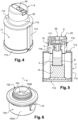
- a device 1 of the present disclosure for sampling and/or injecting a radioactive solution S packaged in a vial 2 (here a vial of the type named "Mallinckrodt" (registered trademark )).
- the vial 2 is standard.
- the vial 2 consists of a container made of glass or transparent plastic which ends at the top by a collar or neck delimiting an opening closed by a puncturable closure member 3 (also known as a septum).
- This closure member 3 may be made of plastics, rubber or the like.
- the radioactive solution S may be any solution emitting ionizing radiation, for example technetium 99.
- the device 1 for sampling and/or injection therefore may comprise:
- radioprotective materials used are standard in the domain of the devices which provide protection against ionizing radiation.
- these materials consist of tungsten and/or lead glass, whose thicknesses are adapted to the type of radioactive solution used, and depending on the desired protection for operators.
- the vial adaptor 4 and the syringe adaptor 5 are here represented in a simplified pictorial illustration and in particular without detailing their internal structure providing fluidic communication therethrough.
- the vial adaptor 4 and the syringe adaptor 5 can be removably and sealingly connected.
- the container 7, adapted to receive the vial 2 and the vial adaptor 4 is formed at least partly of a radioprotective material providing protection against ionizing radiation (for example tungsten and/or lead glass) and comprises:
- the container body 71 also shown in Figures 4 and 5 , comprises a base member 712 which is extended by a cylindrical wall 713.
- This cylindrical wall 713 comprises, at the top, a circular crown 714 from the central area of which extends a cylindrical collar 715 which defines said opening 711.
- the cylindrical wall 713 may include a transparent window to allow visual access to the contents of the container body.
- an internal surface of the cylindrical wall 713 may have a bright color such as white or the like.
- the outer surface of the cylindrical collar 715 has means for detachable connection with the vial adaptor support structure 72, here in the form of a thread 716.
- the means for detachable connection between the vial adaptor support structure and the container body may be of any type such as bayonet coupling, quarter turn, snapping, clipping and the like.
- This thread 716 is adapted to cooperate with attachment means in the form of a complementary thread 721 of the vial adaptor support structure 72 ( Figure 3 ), or with a complementary thread 91 of a cover 9 adapted to seal removably the opening 711 of the container body 71 ( figures 4 and 5 ).
- the cover 9 is made of a radioprotective material providing protection against ionizing radiation (for example tungsten and/or lead glass).
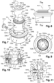
- the vial adaptor support structure 72 shown in isolation in Figures 6 to 12 , is generally tubular, with a longitudinal axis A, and it comprises, disposed coaxially:
- the tubular sleeve 722 having a longitudinal axis C, is delimited by an inner face 7221, by an outer face 7222, an end 7223, said "lower end", and by an end 7224, said "upper end”.
- the inner face 7221 of the tubular sleeve 722 includes said thread 721 adapted to cooperate with the thread 716 of the container body 71.
- These threads 721 and 716 allow detachably mounting of the vial adaptor support structure 72 onto the opening 711 of the container body 71.
- the outer surface 7222 of the tubular sleeve 722 includes a thread 7225 adapted to cooperate with the thread 91 of the cover 9.
- the threads 716, 721, 7225 and 91 of the container body 71, tubular sleeve 722 and cover 9, can be replaced by other means of removable attachment such as quarter turn or bayonet type assemblies.
- the support ring 723 is delimited by an inner surface 7231, by an outer surface 7232, by an end 7233, said "lower end”, oriented towards the lower end 7223 of the tubular sleeve 722, and by an end 7234, said "upper end”, oriented towards the upper end 7224 of the tubular sleeve 722.
- the inner surface 7231 of the support ring 723 defines an internal space 7231a whose geometry is configured to receive the vial adaptor 4, by engagement of the front portion 43 thereof through the lower end 7233, and so as to block translation of said vial adaptor 4, in this engagement direction along its longitudinal axis L1, and to prevent its rotation about said longitudinal axis L1.
- the inner surface 7231 comprises:
- the support ring 723 may be made of plastic.
- the jacket 724 is defined by an inner surface 7241, by an outer surface 7242, by an end 7243, said "lower end”, oriented towards the lower end 7223 of the tubular sleeve 722 and the lower end 7233 of the support ring 723, and by an end 7244, said "upper end”, oriented towards the upper end 7224 of the tubular sleeve 722 and the upper end 7234 of the support ring 723.
- the inner surface 7241 of the jacket 724 is adapted to come opposite the outer face 7222 of the tubular sleeve 722.
- the outer surface 7242 includes a projecting bead 7245 to facilitate its handling, in view of its operation, as explained later in the description.
- the jacket 724 can be made of plastic.
- the vial adaptor support structure 72 comprises retention means configured for enabling releasable retention (i.e. releasable holding) of the vial adaptor 4, and transfer means for imparting to said vial adaptor 4 a (single) degree of freedom in longitudinal translation along its longitudinal axis L1, relative to said container 7 and in particular with respect to said attachment means 721. This enables the puncture of the closure member by a translation movement i.e. without rotation of the spike into the closure member.
- the support ring 723 and the jacket 724 are joined together through fastening means constituted of two assembly lugs 726 and 727 which pass through oblong holes 728 formed in the tubular sleeve 722.
- the two sets of lugs 726, 727 and oblong holes 728 are arranged diametrically opposite with respect to the longitudinal axis A.
- the two oblong holes 728 comprise - a major axis (or length) extending parallel to the longitudinal axis A, and - a short axis (or width) slightly larger than the diameter of lugs 726, 727.
- the first assembly lug 726 is shaped like a radial pin having an inner end 7261 provided with a thread 7262 which cooperates with a threaded hole 7237 formed in the support ring 723.
- the outer end 7263 of the radial pin 726 is housed in a cylindrical hole 7246 formed in the jacket 724.
- This outer end 7263 comprises a groove-shaped recess 7264 enabling it to maneuver in rotation by a tool such as a screwdriver.
- the second assembly lug 727 is shaped like a radial pin having an inner end 7271 provided with a thread 7272 which cooperates with a threaded hole 7238 formed in the support ring 723.
- the outer end 7273 of the radial pin 727 is housed in a cylindrical hole 7247 formed in the jacket 724.
- This outer end 7273 includes a scroll wheel 7274 for its manual rotation maneuver.
- This slight protrusion is adapted so that the inner end 7271 of the radial pin 727 forms a bearing head having the opportunity to come to rest on the side of the vial adaptor 4 in place in the inner space 7231a, so as to tighten against the support ring 723 and constitute at least a part of the aforementioned retention means.
- the radial pin 727 is indeed movable radially between:
- the radial pin 727 associated with the scroll wheel 7274 may be replaced by other means such as a button mounted on a support spring or the like.
- the radial pin 727 thus serves as fastening means between the support ring 723 and the jacket 724, and as retention means between, on one hand, the assembly comprising the support ring 723 and the jacket 724, and, on the other hand, the vial adaptor 4.
- these two functions may be provided separately, in which case the clamping pin will not be used in the connection between the support ring 723 and the jacket 724.
- the length of the oblong holes 728 determines the maximum degree of freedom in translation between the tubular sleeve 722 and the assembly comprising the support ring 723 and the jacket 724 (this degree of freedom in translation being limited by the abutment of the assembly lugs 726, 727 against the ends of oblong holes 728).
- the vial adaptor support structure 72 includes indexing means, in at least one position, of the assembly comprising the vial adaptor 4, the support ring 723 and the jacket 724, relative the tubular sleeve 722.
- the vial adaptor support structure 72 includes indexing means with two positions, one high and the other low, consisting of:
- the balls of the locks 7227 can be matched with the circular recess 7249 for achieving high indexing position.
- the upper ends 7234 and 7244 of the support ring 723 and jacket 724 (extending at the same level or almost the same level), are located beneath the level of the upper portion 7224 of the tubular sleeve 722, the thread 7225 of said tubular sleeve 722 projecting over said jacket 724 and the front portion 43 of the vial adaptor 4 being completely or substantially completely surrounded by said tubular sleeve 722.
- retractable ball lock 7227 may be replaced by other indexing means.
- the vial 2 containing the radioactive solution S is placed in the container body 71 to protect operators against ionizing radiation emitted by said radioactive solution S.
- the opening 711 of the container body 71 is closed by means of the cover 9, by screwing the thread 91 on the thread 716 of the cylindrical collar 715, as shown in Figures 4 and 5 .
- the structure of the container body 71 and that of the associated cover 9, is adapted to retain the vial 2 in the container 7. More specifically, the vial 2 is clamped between the bottom 712 of the container body 71 and the cover 9.
- the container body 71 and the cover 9 are adapted to allow the reception and the retention of different vial models (for example "Mallinckrod”, “IBA” or “GE-General Electric” models (registered trademarks)), optionally by means of a reported wedge 10 (i.e. a height adaptor) disposed between the bottom 712 of the container body 71 and the vial 2.
- a reported wedge 10 i.e. a height adaptor
- the height adaptor may be made of a compressible material so as to cushion the vial into the container body and provide some tolerance with regard to the vial dimensions. Such material may advantageously withstand alcoholic disinfection.
- the height adaptor may be made of rubber, latex, foam, silicon or the like.
- the cover 9 is also preferably equipped with an opening 92 associated with a hatch system 93 that allows, in the position of hatch 93 open, an injection or a removal of the solution S in the vial 2 by means of a syringe or using another suitable means, through the opening 92.
- the hatch system may be operated without protruding out from the cover 9, for example by being configured to be pivoted in the opening plane to selectively cover and uncover the opening 92.
- the opening 92 of the cover 9 is closed by a material providing protection against ionizing radiation, and the vial 2 is then completely surrounded by a radioprotective material.
- the sampling and/or injection of the radioactive solution S can be made by means of an equipment comprising a vial adaptor 4 and a syringe adaptor 5, as described below, with the vial adaptor support structure 72, as described below in connection with figures 13, 14 and 15 .
- the vial adaptor 4 is placed in the vial adaptor support structure 72 by engaging its front portion 43 in the lower end 7233 of the support ring 723, after proper angular orientation, so that the flat portions 7236 come into correspondence of the aforementioned side flat surfaces of the vial adaptor 4, and this until the conical surface 44 of the vial adaptor 4 abuts (or is clamped) against the conical surface 7235 of the support ring 723.
- the front portion 43 of the vial adaptor 4 is then located on the side of upper ends of the support ring 723, tubular sleeve 722 and jacket 724, of the vial adaptor support structure 72; and the hollow spike 42 of the vial adaptor 4 is located on the side of the lower ends of the support ring 723, tubular sleeve 722 and jacket 724 of the vial adaptor support structure 72.
- the assembly comprising the support ring 723 and the jacket 724 is assembled with the vial adaptor 4 by tightening of the radial pin 727 by means of the scroll wheel 7274.
- the vial adaptor may secured in the vial adaptor support structure using the releasable retention means.
- the assembly support ring 723/jacket 724/vial adaptor 4 is then placed in the high position relative to the tubular sleeve 722 by positioning the ball locks 7227 in the lower recess 7249 of the jacket 724.
- the vial adaptor support structure 72 is assembled with said container body 71 by screwing the thread 721 of the tubular sleeve 722 on the thread 716 of the neck of container 715. In other words, the vial adaptor support structure is then mounted on the body container using the detachable connection means.
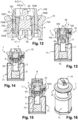
- a container 7 illustrated in Figure 13 with the vial adaptor 4 positioned just above the vial 2, coaxially thereto, and in particular to its opening 711, and with the hollow spike 42 positioned facing the puncturable closure member 3 at a slight distance from the latter (e.g. of the order of a few millimeters).
- tubular sleeve 722 extends the protection of the container body 71 almost until the top of the vial adaptor 4.
- the next operation consists in positioning the vial adaptor 4 on the upper portion of the vial 2, by lowering the assembly comprising the support ring 723, the jacket 724 and the vial adaptor 4, to ensure the piercing of the puncturable closure member 3, by the hollow spike 42 of the vial adaptor 4.
- This piercing is designed optimally by the translation of the assembly comprising the support ring 723 and the jacket 724 on the tubular sleeve 722, guided by the assembly lugs 726, 727 that are movable in the oblong holes 728 ( Figure 14 ).
- a linear puncturing of the closure member is performed using the transfer means to translate the vial adaptor.
- the indexing means may provide for a stopper configured to selectively maintain the vial adaptor in the high and low positions.
- the cover 9 can then be positioned on the vial adaptor support structure 72 by engagement of its thread 91 with the upper thread 7225 of the tubular sleeve 722, as illustrated in Figures 15 and 16 , to ensure a complete peripheral radioprotection, prior to further operations of sampling / injection of the radioactive solution S.
- the container 7 containing the vial 2 of radioactive solution S is then ready to receive the syringe 6 equipped with the syringe adaptor 5 (by assembling the front portions 43 and 52 of the vial adaptor 4 and syringe adaptor 5) as shown in figures 1 to 3 .
- the assembly comprising the vial 2, the vial adaptor 4, the syringe adaptor 5 and the syringe 6 is then substantially completely covered with a radioprotective material providing protection against ionizing radiation.
- the syringe 6 can be used to carry out sampling and/or desired injection, and this syringe 6 can be separated from the vial 2 by disassembling the vial adaptor 4 with respect to the syringe adaptor 5 to perform other operations, such as a mixture of draw volume of radioactive solution S with a tracer before injection into a patient.
- the vial adaptor 4 can be separated from the vial adaptor support structure 72 (in particular for its replacement) by unscrewing the tubular sleeve 722, and then by release of the radial pin 727 by means of the maneuver scroll wheel 7274.
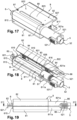
- sampling and/or injection syringe 6, and its protection device 8 in the form of a radioprotective shield are detailed in Figures 17 to 24 .
- the syringe 6, of conventional type comprises a cylindrical body 61, having a longitudinal axis B, equipped at its front end 611 with an end tip 612 provided with an orifice for the passage of liquid to be sampled or to be injected, connected here to the rear portion 51 of the syringe adaptor 5.
- the syringe body 61 has an opening 614 for the passage of a piston 62 with a maneuvering head 621.
- the opening 614 of the syringe body 61 is bordered by lateral wings 615 for easy maneuvering of the piston 62.
- the protection device 8 is in the form of a clamp comprising two half-jaws 81, 82 joined together by a hinge 83 associated with biasing means 84.
- Each half-jaw 81, 82 includes a half-shell, respectively 811, 821, made of radioprotective material providing protection against ionizing radiation (for example tungsten), assembled with a plastic base 812, 822.
- ionizing radiation for example tungsten
- the two plastic bases 812, 822 each include a body 813, 823 provided with an inner face 814, 824, which inner faces 814, 824 are arranged opposite one another.
- each of said longitudinal edges 815, 825 comprises cylindrical elements 816, 826, intended to come into line with one another, for positioning a cylindrical axis 85 embodying the hinge 83.
- the elastic return means 84 here comprise two spiral springs carried by the ends of the axis 85 and acting on the bases 812, 822 so as to tend to bring closer their inner faces 814, 824.
- each of said bases 812, 822 includes an projection 817, 827 on the other side of the hinge 83 relative to the body 813, 823, which comprise operating arms for the opening and closing operations of the shaped clamp protection device 8.
- the maneuvering means 83, 84, 817, 827 are adapted to provide the half-jaws 81, 82 with:
- the half-shells 811 and 821 each have a semi-cylindrical overall shape, whose concave portions are oriented opposite one another; and they are carried by the base body 813, 823 so as to allow:
- the half-shells 811, 821 comprise an protrusion 811a, 821a adapted to cover substantially entirely the syringe adaptor 5.
- said half-shells may include protrusions which projects longitudinally so as to at least partially cover the syringe adaptor.
- protrusions 811a, 821a for covering the syringe adaptor 5 includes a notch 86 allowing the passage of the aforementioned lateral extensions 521. This removes the requirement to have a complex form of protective half-shell, while the risk of release of radiation at this level is limited.
- the two longitudinal sides of one of the half shells include a small projecting lip 821b adapted to overlie the longitudinal side which is in contact with the other half-shell (in this case the half-shell 811), in said closed position, so as to optimize protection.
- the half-jaw bases 812, 822 comprising the base body 813, 823, the cylindrical portions 816, 826 and the projections 817, 827 are formed integrally by plastic injection molding.
- the base body 813, 823 cover the entire portion of the half shells 811, 821 to protect the syringe body 61; and the protrusions 811a, 821a intended to cover the syringe adaptor 5 are protruding and have no plastic base.
- the base body 813, 823 may cover the half shells 811, 821, 811a and 821a over a larger or shorter length.
- Each half-shell 811, 821 is assembled with its base 812, 822 by means of screws 87 (here there are two per half shell).
- one of the half-jaws 81, 82, or both may comprise a transparent window 88 extending through the half-shell 811, 821 and the associated base 812, 822, made of a material providing protection against ionizing radiation, such as lead glass.
- such a protection device 8 in the form of hinged clamp is very easy to position on a syringe 6, by simple manual opening of the half-jaws 81, 82 (pivoting around the hinge 83 by pressing the arm 817, 827), then by introducing the entire syringe body 61/syringe adaptor 5, and then relaxing the bearing force on the arms 817, 827.
- the syringe 6 can be removed from its protection device 8 in a similar way.
- Such a protection device 8 designed as a clamp can be adapted to other types of syringes, for example syringes that are devoid of a syringe adaptor; and it can be considered independently of the container 7 as described above.
Landscapes
- Health & Medical Sciences (AREA)
- Public Health (AREA)
- Veterinary Medicine (AREA)
- General Health & Medical Sciences (AREA)
- Life Sciences & Earth Sciences (AREA)
- Animal Behavior & Ethology (AREA)
- Pharmacology & Pharmacy (AREA)
- Physics & Mathematics (AREA)
- Engineering & Computer Science (AREA)
- Fluid Mechanics (AREA)
- Biomedical Technology (AREA)
- Anesthesiology (AREA)
- Vascular Medicine (AREA)
- Heart & Thoracic Surgery (AREA)
- Hematology (AREA)
- General Engineering & Computer Science (AREA)
- High Energy & Nuclear Physics (AREA)
- Medical Preparation Storing Or Oral Administration Devices (AREA)
- Nuclear Medicine (AREA)
- Measurement Of Radiation (AREA)
- Sampling And Sample Adjustment (AREA)
Claims (8)
- Dispositif utile pour l'échantillonnage et/ou l'injection d'une solution radioactive (S) dans un flacon (2), ledit flacon (2) comportant une ouverture fermée par un élément de fermeture perforable (3), ledit dispositif comprenant :un récipient (7) adapté à la réception dudit flacon (2) et d'un adaptateur de flacon (4), ledit adaptateur de flacon (4) comportant un axe longitudinal (L1), pourvu au niveau d'une première extrémité (41) d'une pointe creuse (42) adaptée au perçage dudit élément de fermeture perforable (3) lorsque l'adaptateur de flacon (4) est monté sur le flacon (2) et au niveau d'une seconde extrémité (43) avec un moyen de raccordement (43) adapté au raccordement amovible à un adaptateur de seringue (5),ledit récipient (7) comprenant :- un corps de récipient (71) adapté à la réception dudit flacon (2), le corps de récipient (71) comportant une ouverture (711), et- une structure de support d'adaptateur de flacon (72) conçue pour être montée sur l'ouverture (711) du corps de récipient (71), et comprenant des moyens de rétention (727 ; 7235, 44) conçus pour permettre une rétention libérable dudit adaptateur de flacon (4) à l'intérieur de ladite structure de support d'adaptateur de flacon (72), etladite structure de support d'adaptateur de flacon (72) et ledit corps de récipient (71) étant constitués au moins partiellement d'un matériau radioprotecteur destiné à assurer une protection contre un rayonnement ionisant ;ladite structure de support d'adaptateur de flacon (72) comprenant en outre un moyen de transfert destiné à conférer audit adaptateur de flacon un degré de liberté en translation longitudinale le long de son axe longitudinal L1, par rapport audit récipient (7) et en particulier par rapport à un moyen de fixation (721) conçu pour permettre le montage de la structure de support d'adaptateur de flacon (72) sur l'ouverture (711) du corps de récipient (71), à cet effet, un anneau support (723) et une enveloppe (724) sont réunis ensemble par l'intermédiaire d'un moyen de fixation constitué de deux pattes d'assemblage (726) et (727) qui traversent des trous oblongs (728) ménagés dans un manchon tubulaire (722),ladite enveloppe (724) étant conçue pour faire fonctionner l'anneau support (723) selon ledit degré de liberté en translation, ladite enveloppe (724) entourant au moins partiellement ledit manchon tubulaire (722),ledit anneau support (723) étant disposé à l'intérieur du manchon tubulaire (722), et adapté au soutien de l'adaptateur de flacon, ladite enveloppe (724) étant disposée à l'extérieur dudit manchon tubulaire (722) adapté à la manoeuvre de l'anneau support (723),ledit moyen de fixation (721) étant adapté à une coopération avec le moyen d'engagement correspondant (716) du corps de récipient (71),l'abaissement de l'ensemble comprenant l'anneau support (723), l'enveloppe (724) et l'adaptateur de flacon provoquant le perçage de l'élément de fermeture perforable (3) par la pointe creuse (42) de l'adaptateur de flacon,et ledit perçage étant conçu de manière optimale par la translation de l'ensemble comprenant l'anneau support (723) et l'enveloppe (724) sur le manchon tubulaire (722), guidé par les pattes d'assemblage (726), (727) qui sont mobiles dans les trous oblongs (728).
- Dispositif selon la revendication 1, caractérisé en ce que la structure de support d'adaptateur de flacon (72) est généralement tubulaire avec un axe longitudinal (A) et :- ledit manchon tubulaire (722) comportant une première extrémité (7223) munie d'un moyen de fixation (721) conçu pour permettre le montage de la structure de support d'adaptateur de flacon (72) sur l'ouverture (711) du corps de récipient (71),- ledit anneau support (723), reçu dans ledit manchon tubulaire (722), coaxial au manchon tubulaire (722), et définissant un espace interne (7231a) pour la réception dudit adaptateur de flacon (4),les moyens de transfert étant en outre conçus pour conférer audit anneau support (723) un degré de liberté en translation longitudinale le long dudit axe longitudinal (A) par rapport audit manchon tubulaire (722), etlesdits moyens de rétention (727 ; 7235, 44) étant en outre conçus pour permettre le raccordement dudit adaptateur de flacon (4) avec ledit anneau support (723).
- Dispositif selon la revendication 1, caractérisé en ce que lesdits moyens de rétention comprennent un goujon d'appui radial (727) fixé avec ladite enveloppe (724) et/ou ledit anneau support (723), ledit goujon d'appui (727) comportant une extrémité externe (7273) accessible sur une périphérie externe de ladite enveloppe (724), munie d'un organe de manoeuvre (7274), et d'une extrémité interne (7271) formant une tête d'appui, et ledit goujon d'appui (727) étant mobile radialement entre :- une position active dans laquelle ladite tête d'appui (7271) s'étend dans ledit espace interne (7231a) dudit anneau support (723) et est adaptée à la venue en butée contre ledit adaptateur de flacon (4) afin d'assembler ledit adaptateur de flacon avec ledit anneau support (723) et/ou ladite enveloppe (724), et- une position inactive dans laquelle ladite tête d'appui (7271) ne vient pas en butée contre ledit adaptateur de flacon (4).
- Dispositif selon la revendication 3 lorsqu'elle dépend de la revendication 1, caractérisé en ce que ledit goujon d'appui (727) est également l'une desdites pattes d'assemblage.
- Dispositif selon l'une quelconque des revendications 2 à 4, caractérisé en ce que le dispositif comprend en outre des moyens d'indexation (7227, 7248, 7249) vers au moins une position, de l'ensemble comprenant l'adaptateur de flacon (4), l'anneau support (723) et l'enveloppe (724), par rapport audit manchon tubulaire (722).
- Dispositif selon la revendication 5, caractérisé en ce que lesdits moyens d'indexation comprennent au moins un dispositif de verrouillage à bille rétractable (7227) monté sur un élément parmi le manchon tubulaire (722) ou l'enveloppe (724) coopérant avec un évidement (7248, 7249) pourvu sur l'autre élément parmi le manchon tubulaire (722) ou l'enveloppe (724).
- Dispositif selon l'une quelconque des revendications 2 à 6, caractérisé en ce que ledit anneau support (723) comprend un premier moyen de positionnement (7235) conçu pour bloquer ledit adaptateur de flacon (4) dans un sens le long de son axe longitudinal (L1), et un second moyen de positionnement (7236) adapté à l'empêchement de la rotation dudit adaptateur de flacon (4) autour dudit axe longitudinal (L1).
- Dispositif selon l'une quelconque des revendications 1 à 7, comprenant en outre :une seringue (6) comprenant un corps de seringue (61), un piston (62) et un adaptateur de seringue (5) conçu pour être raccordé audit adaptateur de flacon (4), etun dispositif de protection (8) présentant la forme d'un blindage constitué d'un matériau radioprotecteur assurant une protection contre un rayonnement ionisant, ledit dispositif de protection (8) recouvrant au moins partiellement ledit corps de seringue (61) et ledit adaptateur de seringue (5).
Applications Claiming Priority (2)
| Application Number | Priority Date | Filing Date | Title |
|---|---|---|---|
| EP16172870 | 2016-06-03 | ||
| PCT/EP2017/063452 WO2017207758A2 (fr) | 2016-06-03 | 2017-06-02 | Dispositif de protection utile pour manipuler une solution radioactive |
Publications (3)
| Publication Number | Publication Date |
|---|---|
| EP3463251A2 EP3463251A2 (fr) | 2019-04-10 |
| EP3463251C0 EP3463251C0 (fr) | 2024-02-21 |
| EP3463251B1 true EP3463251B1 (fr) | 2024-02-21 |
Family
ID=56134107
Family Applications (1)
| Application Number | Title | Priority Date | Filing Date |
|---|---|---|---|
| EP17727874.4A Active EP3463251B1 (fr) | 2016-06-03 | 2017-06-02 | Dispositif de blindage utile pour la manipulation d'une solution radioactive |
Country Status (8)
| Country | Link |
|---|---|
| US (2) | US10639420B2 (fr) |
| EP (1) | EP3463251B1 (fr) |
| JP (1) | JP7113763B2 (fr) |
| CA (1) | CA3025593A1 (fr) |
| ES (1) | ES2974642T3 (fr) |
| HU (1) | HUE066556T2 (fr) |
| IL (1) | IL263146B (fr) |
| WO (1) | WO2017207758A2 (fr) |
Families Citing this family (1)
| Publication number | Priority date | Publication date | Assignee | Title |
|---|---|---|---|---|
| FR3133601B1 (fr) * | 2022-03-17 | 2024-09-06 | Lemer Pax | Conteneur blindé pour le transport d’un récipient contenant un produit radioactif |
Family Cites Families (10)
| Publication number | Priority date | Publication date | Assignee | Title |
|---|---|---|---|---|
| US6162198A (en) | 1996-06-11 | 2000-12-19 | Syncor International Corporation | Injection shield and method for discharging a syringe containing radioactive material |
| US20040249235A1 (en) | 2003-06-03 | 2004-12-09 | Connell Edward G. | Hazardous material handling system and method |
| SI2463201T1 (sl) | 2003-10-30 | 2014-06-30 | Teva Medical Ltd. | Naprava za varno obdelavo zdravila |
| CA2612461C (fr) * | 2005-07-27 | 2013-11-19 | Mallinckrodt Inc. | Ensembles de protection contre le rayonnement et procedes d'utilisation de ces derniers |
| ES2425579T3 (es) | 2006-05-25 | 2013-10-16 | Bayer Healthcare, Llc | Dispositivo de reconstitución |
| EP2139541B1 (fr) * | 2007-01-01 | 2018-04-11 | Bayer Healthcare LLC | Systèmes permettant la génération, la préparation, le transport et l'administration radiopharmaceutiques intégrés |
| DE102007006189B4 (de) | 2007-02-07 | 2009-07-30 | Isotopen Technologien München AG | Vorrichtung zum Befüllen eines medizinischen Instruments mit einer radioaktiven Substanz und Verfahren |
| WO2009007350A1 (fr) * | 2007-07-06 | 2009-01-15 | Universite Libre De Bruxelles | Dispositif et procédé pour la préparation et l'utilisation de produits radiopharmaceutiques |
| US9233776B2 (en) | 2012-06-07 | 2016-01-12 | Bayer Healthcare Llc | Molecular imaging vial transport container and fluid injection system interface |
| US9125976B2 (en) | 2012-06-07 | 2015-09-08 | Bayer Medical Care Inc. | Shield adapters |
-
2017
- 2017-06-02 WO PCT/EP2017/063452 patent/WO2017207758A2/fr not_active Ceased
- 2017-06-02 JP JP2018563514A patent/JP7113763B2/ja active Active
- 2017-06-02 US US15/611,897 patent/US10639420B2/en active Active
- 2017-06-02 EP EP17727874.4A patent/EP3463251B1/fr active Active
- 2017-06-02 CA CA3025593A patent/CA3025593A1/fr active Pending
- 2017-06-02 ES ES17727874T patent/ES2974642T3/es active Active
- 2017-06-02 HU HUE17727874A patent/HUE066556T2/hu unknown
-
2018
- 2018-11-20 IL IL263146A patent/IL263146B/en unknown
-
2020
- 2020-05-04 US US16/865,837 patent/US20200261651A1/en not_active Abandoned
Also Published As
| Publication number | Publication date |
|---|---|
| US20200261651A1 (en) | 2020-08-20 |
| US20170348485A1 (en) | 2017-12-07 |
| HUE066556T2 (hu) | 2024-08-28 |
| JP2019517336A (ja) | 2019-06-24 |
| WO2017207758A3 (fr) | 2018-01-18 |
| US10639420B2 (en) | 2020-05-05 |
| EP3463251C0 (fr) | 2024-02-21 |
| IL263146B (en) | 2022-06-01 |
| WO2017207758A2 (fr) | 2017-12-07 |
| IL263146A (en) | 2018-12-31 |
| JP7113763B2 (ja) | 2022-08-05 |
| CA3025593A1 (fr) | 2017-12-07 |
| ES2974642T3 (es) | 2024-06-28 |
| EP3463251A2 (fr) | 2019-04-10 |
Similar Documents
| Publication | Publication Date | Title |
|---|---|---|
| US11690786B2 (en) | Adapter for vial access device | |
| RU2141306C1 (ru) | Шприцевое устройство для смешивания двух компонентов | |
| AU2006311268B2 (en) | Syringe devices, components of syringe devices, and methods of forming components and syringe devices | |
| JP4187790B2 (ja) | 薬剤ガラス瓶に詰められた薬剤のための配達方式 | |
| AU633431B2 (en) | Suction transfer assembly | |
| AU2013346797B2 (en) | Injection needle assembly | |
| US10456067B2 (en) | Blood collection assembly | |
| US6464105B1 (en) | Device for withdrawing a ready liquid medicament from a receptacle provided with a pierceable membrane | |
| KR20150082353A (ko) | 약제 용기 수용 장치, 약제 용기 수용 시스템, 및 약제의 석션 방법 | |
| US11992463B2 (en) | Connector for connecting a medical injection device to a container | |
| US7772565B2 (en) | Radiation-shielding assembly having container location feature | |
| EP1272242A4 (fr) | Dispositif de protection d'aiguille s'utilisant avec un flacon | |
| EP3463251B1 (fr) | Dispositif de blindage utile pour la manipulation d'une solution radioactive | |
| EP3127573A1 (fr) | Seringue et dispositif de sécurité pour aiguille de seringue | |
| JP2018516686A (ja) | 注射用ペンに容器を装着するためのハウジング、注射用ペン用の注射剤貯槽を形成するアセンブリ、およびそのアセンブリを具備する注射用ペン | |
| US20030226981A1 (en) | Beta radiation shielding system | |
| CN114585344B (zh) | 用于连接医疗注射装置和容器的连接器和包括所述连接器和医疗注射装置的组件 | |
| KR100360586B1 (ko) | 2종의화합물을혼합하는주사장치 | |
| CA2783251A1 (fr) | Dispositif de reconstitution avec couvercle d'embout | |
| CA3226420A1 (fr) | Capuchon de fermeture et systeme de fermeture pour une seringue pre-remplie avec un medicament ou une substance active medicale | |
| KR20140130902A (ko) | 주사바늘 보호캡 |
Legal Events
| Date | Code | Title | Description |
|---|---|---|---|
| STAA | Information on the status of an ep patent application or granted ep patent |
Free format text: STATUS: UNKNOWN |
|
| STAA | Information on the status of an ep patent application or granted ep patent |
Free format text: STATUS: THE INTERNATIONAL PUBLICATION HAS BEEN MADE |
|
| PUAI | Public reference made under article 153(3) epc to a published international application that has entered the european phase |
Free format text: ORIGINAL CODE: 0009012 |
|
| STAA | Information on the status of an ep patent application or granted ep patent |
Free format text: STATUS: REQUEST FOR EXAMINATION WAS MADE |
|
| 17P | Request for examination filed |
Effective date: 20181128 |
|
| AK | Designated contracting states |
Kind code of ref document: A2 Designated state(s): AL AT BE BG CH CY CZ DE DK EE ES FI FR GB GR HR HU IE IS IT LI LT LU LV MC MK MT NL NO PL PT RO RS SE SI SK SM TR |
|
| AX | Request for extension of the european patent |
Extension state: BA ME |
|
| DAV | Request for validation of the european patent (deleted) | ||
| DAX | Request for extension of the european patent (deleted) | ||
| RAP1 | Party data changed (applicant data changed or rights of an application transferred) |
Owner name: SIMPLIVIA HEALTHCARE LTD. |
|
| STAA | Information on the status of an ep patent application or granted ep patent |
Free format text: STATUS: EXAMINATION IS IN PROGRESS |
|
| 17Q | First examination report despatched |
Effective date: 20210907 |
|
| REG | Reference to a national code |
Ref country code: DE Ipc: A61J0001140000 Ref legal event code: R079 Ref document number: 602017079321 Country of ref document: DE Free format text: PREVIOUS MAIN CLASS: A61J0001200000 |
|
| GRAP | Despatch of communication of intention to grant a patent |
Free format text: ORIGINAL CODE: EPIDOSNIGR1 |
|
| STAA | Information on the status of an ep patent application or granted ep patent |
Free format text: STATUS: GRANT OF PATENT IS INTENDED |
|
| GRAS | Grant fee paid |
Free format text: ORIGINAL CODE: EPIDOSNIGR3 |
|
| RIC1 | Information provided on ipc code assigned before grant |
Ipc: G21F 5/018 20060101ALI20231205BHEP Ipc: A61M 5/178 20060101ALI20231205BHEP Ipc: A61J 1/20 20060101ALI20231205BHEP Ipc: G21F 5/015 20060101ALI20231205BHEP Ipc: A61J 1/16 20060101ALI20231205BHEP Ipc: A61J 1/14 20060101AFI20231205BHEP |
|
| INTG | Intention to grant announced |
Effective date: 20231220 |
|
| GRAA | (expected) grant |
Free format text: ORIGINAL CODE: 0009210 |
|
| STAA | Information on the status of an ep patent application or granted ep patent |
Free format text: STATUS: THE PATENT HAS BEEN GRANTED |
|
| AK | Designated contracting states |
Kind code of ref document: B1 Designated state(s): AL AT BE BG CH CY CZ DE DK EE ES FI FR GB GR HR HU IE IS IT LI LT LU LV MC MK MT NL NO PL PT RO RS SE SI SK SM TR |
|
| REG | Reference to a national code |
Ref country code: GB Ref legal event code: FG4D |
|
| REG | Reference to a national code |
Ref country code: CH Ref legal event code: EP |
|
| REG | Reference to a national code |
Ref country code: DE Ref legal event code: R096 Ref document number: 602017079321 Country of ref document: DE |
|
| REG | Reference to a national code |
Ref country code: IE Ref legal event code: FG4D |
|
| U01 | Request for unitary effect filed |
Effective date: 20240319 |
|
| U07 | Unitary effect registered |
Designated state(s): AT BE BG DE DK EE FI FR IT LT LU LV MT NL PT SE SI Effective date: 20240327 |
|
| REG | Reference to a national code |
Ref country code: ES Ref legal event code: FG2A Ref document number: 2974642 Country of ref document: ES Kind code of ref document: T3 Effective date: 20240628 |
|
| PG25 | Lapsed in a contracting state [announced via postgrant information from national office to epo] |
Ref country code: IS Free format text: LAPSE BECAUSE OF FAILURE TO SUBMIT A TRANSLATION OF THE DESCRIPTION OR TO PAY THE FEE WITHIN THE PRESCRIBED TIME-LIMIT Effective date: 20240621 |
|
| PG25 | Lapsed in a contracting state [announced via postgrant information from national office to epo] |
Ref country code: GR Free format text: LAPSE BECAUSE OF FAILURE TO SUBMIT A TRANSLATION OF THE DESCRIPTION OR TO PAY THE FEE WITHIN THE PRESCRIBED TIME-LIMIT Effective date: 20240522 |
|
| PG25 | Lapsed in a contracting state [announced via postgrant information from national office to epo] |
Ref country code: RS Free format text: LAPSE BECAUSE OF FAILURE TO SUBMIT A TRANSLATION OF THE DESCRIPTION OR TO PAY THE FEE WITHIN THE PRESCRIBED TIME-LIMIT Effective date: 20240521 Ref country code: HR Free format text: LAPSE BECAUSE OF FAILURE TO SUBMIT A TRANSLATION OF THE DESCRIPTION OR TO PAY THE FEE WITHIN THE PRESCRIBED TIME-LIMIT Effective date: 20240221 |
|
| U20 | Renewal fee for the european patent with unitary effect paid |
Year of fee payment: 8 Effective date: 20240617 |
|
| PG25 | Lapsed in a contracting state [announced via postgrant information from national office to epo] |
Ref country code: RS Free format text: LAPSE BECAUSE OF FAILURE TO SUBMIT A TRANSLATION OF THE DESCRIPTION OR TO PAY THE FEE WITHIN THE PRESCRIBED TIME-LIMIT Effective date: 20240521 Ref country code: NO Free format text: LAPSE BECAUSE OF FAILURE TO SUBMIT A TRANSLATION OF THE DESCRIPTION OR TO PAY THE FEE WITHIN THE PRESCRIBED TIME-LIMIT Effective date: 20240521 Ref country code: IS Free format text: LAPSE BECAUSE OF FAILURE TO SUBMIT A TRANSLATION OF THE DESCRIPTION OR TO PAY THE FEE WITHIN THE PRESCRIBED TIME-LIMIT Effective date: 20240621 Ref country code: HR Free format text: LAPSE BECAUSE OF FAILURE TO SUBMIT A TRANSLATION OF THE DESCRIPTION OR TO PAY THE FEE WITHIN THE PRESCRIBED TIME-LIMIT Effective date: 20240221 Ref country code: GR Free format text: LAPSE BECAUSE OF FAILURE TO SUBMIT A TRANSLATION OF THE DESCRIPTION OR TO PAY THE FEE WITHIN THE PRESCRIBED TIME-LIMIT Effective date: 20240522 |
|
| PG25 | Lapsed in a contracting state [announced via postgrant information from national office to epo] |
Ref country code: PL Free format text: LAPSE BECAUSE OF FAILURE TO SUBMIT A TRANSLATION OF THE DESCRIPTION OR TO PAY THE FEE WITHIN THE PRESCRIBED TIME-LIMIT Effective date: 20240221 |
|
| REG | Reference to a national code |
Ref country code: HU Ref legal event code: AG4A Ref document number: E066556 Country of ref document: HU |
|
| PG25 | Lapsed in a contracting state [announced via postgrant information from national office to epo] |
Ref country code: PL Free format text: LAPSE BECAUSE OF FAILURE TO SUBMIT A TRANSLATION OF THE DESCRIPTION OR TO PAY THE FEE WITHIN THE PRESCRIBED TIME-LIMIT Effective date: 20240221 |
|
| PG25 | Lapsed in a contracting state [announced via postgrant information from national office to epo] |
Ref country code: SM Free format text: LAPSE BECAUSE OF FAILURE TO SUBMIT A TRANSLATION OF THE DESCRIPTION OR TO PAY THE FEE WITHIN THE PRESCRIBED TIME-LIMIT Effective date: 20240221 |
|
| PG25 | Lapsed in a contracting state [announced via postgrant information from national office to epo] |
Ref country code: CZ Free format text: LAPSE BECAUSE OF FAILURE TO SUBMIT A TRANSLATION OF THE DESCRIPTION OR TO PAY THE FEE WITHIN THE PRESCRIBED TIME-LIMIT Effective date: 20240221 |
|
| PG25 | Lapsed in a contracting state [announced via postgrant information from national office to epo] |
Ref country code: SK Free format text: LAPSE BECAUSE OF FAILURE TO SUBMIT A TRANSLATION OF THE DESCRIPTION OR TO PAY THE FEE WITHIN THE PRESCRIBED TIME-LIMIT Effective date: 20240221 |
|
| PG25 | Lapsed in a contracting state [announced via postgrant information from national office to epo] |
Ref country code: SM Free format text: LAPSE BECAUSE OF FAILURE TO SUBMIT A TRANSLATION OF THE DESCRIPTION OR TO PAY THE FEE WITHIN THE PRESCRIBED TIME-LIMIT Effective date: 20240221 Ref country code: SK Free format text: LAPSE BECAUSE OF FAILURE TO SUBMIT A TRANSLATION OF THE DESCRIPTION OR TO PAY THE FEE WITHIN THE PRESCRIBED TIME-LIMIT Effective date: 20240221 Ref country code: RO Free format text: LAPSE BECAUSE OF FAILURE TO SUBMIT A TRANSLATION OF THE DESCRIPTION OR TO PAY THE FEE WITHIN THE PRESCRIBED TIME-LIMIT Effective date: 20240221 Ref country code: CZ Free format text: LAPSE BECAUSE OF FAILURE TO SUBMIT A TRANSLATION OF THE DESCRIPTION OR TO PAY THE FEE WITHIN THE PRESCRIBED TIME-LIMIT Effective date: 20240221 |
|
| REG | Reference to a national code |
Ref country code: DE Ref legal event code: R097 Ref document number: 602017079321 Country of ref document: DE |
|
| PLBE | No opposition filed within time limit |
Free format text: ORIGINAL CODE: 0009261 |
|
| STAA | Information on the status of an ep patent application or granted ep patent |
Free format text: STATUS: NO OPPOSITION FILED WITHIN TIME LIMIT |
|
| 26N | No opposition filed |
Effective date: 20241122 |
|
| PG25 | Lapsed in a contracting state [announced via postgrant information from national office to epo] |
Ref country code: MC Free format text: LAPSE BECAUSE OF FAILURE TO SUBMIT A TRANSLATION OF THE DESCRIPTION OR TO PAY THE FEE WITHIN THE PRESCRIBED TIME-LIMIT Effective date: 20240221 |
|
| PG25 | Lapsed in a contracting state [announced via postgrant information from national office to epo] |
Ref country code: IE Free format text: LAPSE BECAUSE OF NON-PAYMENT OF DUE FEES Effective date: 20240602 |
|
| PGFP | Annual fee paid to national office [announced via postgrant information from national office to epo] |
Ref country code: GB Payment date: 20250618 Year of fee payment: 9 |
|
| PGFP | Annual fee paid to national office [announced via postgrant information from national office to epo] |
Ref country code: HU Payment date: 20250512 Year of fee payment: 9 |
|
| U20 | Renewal fee for the european patent with unitary effect paid |
Year of fee payment: 9 Effective date: 20250617 |
|
| PG25 | Lapsed in a contracting state [announced via postgrant information from national office to epo] |
Ref country code: CY Free format text: LAPSE BECAUSE OF FAILURE TO SUBMIT A TRANSLATION OF THE DESCRIPTION OR TO PAY THE FEE WITHIN THE PRESCRIBED TIME-LIMIT; INVALID AB INITIO Effective date: 20170602 |
|
| PGFP | Annual fee paid to national office [announced via postgrant information from national office to epo] |
Ref country code: ES Payment date: 20250710 Year of fee payment: 9 |
|
| PGFP | Annual fee paid to national office [announced via postgrant information from national office to epo] |
Ref country code: CH Payment date: 20250701 Year of fee payment: 9 |