EP3463814B1 - Procédé de soudage par induction magnétique d'une paroi d'eau - Google Patents
Procédé de soudage par induction magnétique d'une paroi d'eau Download PDFInfo
- Publication number
- EP3463814B1 EP3463814B1 EP17726881.0A EP17726881A EP3463814B1 EP 3463814 B1 EP3463814 B1 EP 3463814B1 EP 17726881 A EP17726881 A EP 17726881A EP 3463814 B1 EP3463814 B1 EP 3463814B1
- Authority
- EP
- European Patent Office
- Prior art keywords
- tubes
- heating
- magnetic induction
- panel
- welding
- Prior art date
- Legal status (The legal status is an assumption and is not a legal conclusion. Google has not performed a legal analysis and makes no representation as to the accuracy of the status listed.)
- Not-in-force
Links
Images



Classifications
-
- F—MECHANICAL ENGINEERING; LIGHTING; HEATING; WEAPONS; BLASTING
- F22—STEAM GENERATION
- F22B—METHODS OF STEAM GENERATION; STEAM BOILERS
- F22B37/00—Component parts or details of steam boilers
- F22B37/02—Component parts or details of steam boilers applicable to more than one kind or type of steam boiler
- F22B37/10—Water tubes; Accessories therefor
- F22B37/20—Supporting arrangements, e.g. for securing water-tube sets
- F22B37/201—Suspension and securing arrangements for walls built-up from tubes
-
- B—PERFORMING OPERATIONS; TRANSPORTING
- B23—MACHINE TOOLS; METAL-WORKING NOT OTHERWISE PROVIDED FOR
- B23K—SOLDERING OR UNSOLDERING; WELDING; CLADDING OR PLATING BY SOLDERING OR WELDING; CUTTING BY APPLYING HEAT LOCALLY, e.g. FLAME CUTTING; WORKING BY LASER BEAM
- B23K13/00—Welding by high-frequency current heating
- B23K13/01—Welding by high-frequency current heating by induction heating
- B23K13/02—Seam welding
- B23K13/025—Seam welding for tubes
-
- B—PERFORMING OPERATIONS; TRANSPORTING
- B23—MACHINE TOOLS; METAL-WORKING NOT OTHERWISE PROVIDED FOR
- B23K—SOLDERING OR UNSOLDERING; WELDING; CLADDING OR PLATING BY SOLDERING OR WELDING; CUTTING BY APPLYING HEAT LOCALLY, e.g. FLAME CUTTING; WORKING BY LASER BEAM
- B23K26/00—Working by laser beam, e.g. welding, cutting or boring
- B23K26/20—Bonding
- B23K26/21—Bonding by welding
- B23K26/24—Seam welding
- B23K26/26—Seam welding of rectilinear seams
-
- B—PERFORMING OPERATIONS; TRANSPORTING
- B23—MACHINE TOOLS; METAL-WORKING NOT OTHERWISE PROVIDED FOR
- B23K—SOLDERING OR UNSOLDERING; WELDING; CLADDING OR PLATING BY SOLDERING OR WELDING; CUTTING BY APPLYING HEAT LOCALLY, e.g. FLAME CUTTING; WORKING BY LASER BEAM
- B23K31/00—Processes relevant to this subclass, specially adapted for particular articles or purposes, but not covered by any single one of main groups B23K1/00 - B23K28/00
- B23K31/02—Processes relevant to this subclass, specially adapted for particular articles or purposes, but not covered by any single one of main groups B23K1/00 - B23K28/00 relating to soldering or welding
-
- C—CHEMISTRY; METALLURGY
- C21—METALLURGY OF IRON
- C21D—MODIFYING THE PHYSICAL STRUCTURE OF FERROUS METALS; GENERAL DEVICES FOR HEAT TREATMENT OF FERROUS OR NON-FERROUS METALS OR ALLOYS; MAKING METAL MALLEABLE, e.g. BY DECARBURISATION OR TEMPERING
- C21D1/00—General methods or devices for heat treatment, e.g. annealing, hardening, quenching or tempering
- C21D1/34—Methods of heating
- C21D1/42—Induction heating
-
- C—CHEMISTRY; METALLURGY
- C21—METALLURGY OF IRON
- C21D—MODIFYING THE PHYSICAL STRUCTURE OF FERROUS METALS; GENERAL DEVICES FOR HEAT TREATMENT OF FERROUS OR NON-FERROUS METALS OR ALLOYS; MAKING METAL MALLEABLE, e.g. BY DECARBURISATION OR TEMPERING
- C21D9/00—Heat treatment, e.g. annealing, hardening, quenching or tempering, adapted for particular articles; Furnaces therefor
- C21D9/50—Heat treatment, e.g. annealing, hardening, quenching or tempering, adapted for particular articles; Furnaces therefor for welded joints
-
- F—MECHANICAL ENGINEERING; LIGHTING; HEATING; WEAPONS; BLASTING
- F22—STEAM GENERATION
- F22B—METHODS OF STEAM GENERATION; STEAM BOILERS
- F22B37/00—Component parts or details of steam boilers
- F22B37/02—Component parts or details of steam boilers applicable to more than one kind or type of steam boiler
- F22B37/04—Component parts or details of steam boilers applicable to more than one kind or type of steam boiler and characterised by material, e.g. use of special steel alloy
-
- F—MECHANICAL ENGINEERING; LIGHTING; HEATING; WEAPONS; BLASTING
- F22—STEAM GENERATION
- F22B—METHODS OF STEAM GENERATION; STEAM BOILERS
- F22B37/00—Component parts or details of steam boilers
- F22B37/02—Component parts or details of steam boilers applicable to more than one kind or type of steam boiler
- F22B37/10—Water tubes; Accessories therefor
- F22B37/104—Connection of tubes one with the other or with collectors, drums or distributors
-
- H—ELECTRICITY
- H05—ELECTRIC TECHNIQUES NOT OTHERWISE PROVIDED FOR
- H05B—ELECTRIC HEATING; ELECTRIC LIGHT SOURCES NOT OTHERWISE PROVIDED FOR; CIRCUIT ARRANGEMENTS FOR ELECTRIC LIGHT SOURCES, IN GENERAL
- H05B6/00—Heating by electric, magnetic or electromagnetic fields
- H05B6/02—Induction heating
- H05B6/10—Induction heating apparatus, other than furnaces, for specific applications
- H05B6/101—Induction heating apparatus, other than furnaces, for specific applications for local heating of metal pieces
-
- H—ELECTRICITY
- H05—ELECTRIC TECHNIQUES NOT OTHERWISE PROVIDED FOR
- H05B—ELECTRIC HEATING; ELECTRIC LIGHT SOURCES NOT OTHERWISE PROVIDED FOR; CIRCUIT ARRANGEMENTS FOR ELECTRIC LIGHT SOURCES, IN GENERAL
- H05B6/00—Heating by electric, magnetic or electromagnetic fields
- H05B6/02—Induction heating
- H05B6/36—Coil arrangements
- H05B6/40—Establishing desired heat distribution, e.g. to heat particular parts of workpieces
-
- B—PERFORMING OPERATIONS; TRANSPORTING
- B23—MACHINE TOOLS; METAL-WORKING NOT OTHERWISE PROVIDED FOR
- B23K—SOLDERING OR UNSOLDERING; WELDING; CLADDING OR PLATING BY SOLDERING OR WELDING; CUTTING BY APPLYING HEAT LOCALLY, e.g. FLAME CUTTING; WORKING BY LASER BEAM
- B23K2101/00—Articles made by soldering, welding or cutting
- B23K2101/04—Tubular or hollow articles
- B23K2101/06—Tubes
- B23K2101/08—Tubes finned or ribbed
-
- B—PERFORMING OPERATIONS; TRANSPORTING
- B23—MACHINE TOOLS; METAL-WORKING NOT OTHERWISE PROVIDED FOR
- B23K—SOLDERING OR UNSOLDERING; WELDING; CLADDING OR PLATING BY SOLDERING OR WELDING; CUTTING BY APPLYING HEAT LOCALLY, e.g. FLAME CUTTING; WORKING BY LASER BEAM
- B23K2101/00—Articles made by soldering, welding or cutting
- B23K2101/04—Tubular or hollow articles
- B23K2101/14—Heat exchangers
-
- C—CHEMISTRY; METALLURGY
- C21—METALLURGY OF IRON
- C21D—MODIFYING THE PHYSICAL STRUCTURE OF FERROUS METALS; GENERAL DEVICES FOR HEAT TREATMENT OF FERROUS OR NON-FERROUS METALS OR ALLOYS; MAKING METAL MALLEABLE, e.g. BY DECARBURISATION OR TEMPERING
- C21D2221/00—Treating localised areas of an article
-
- C—CHEMISTRY; METALLURGY
- C21—METALLURGY OF IRON
- C21D—MODIFYING THE PHYSICAL STRUCTURE OF FERROUS METALS; GENERAL DEVICES FOR HEAT TREATMENT OF FERROUS OR NON-FERROUS METALS OR ALLOYS; MAKING METAL MALLEABLE, e.g. BY DECARBURISATION OR TEMPERING
- C21D2221/00—Treating localised areas of an article
- C21D2221/10—Differential treatment of inner with respect to outer regions, e.g. core and periphery, respectively
-
- Y—GENERAL TAGGING OF NEW TECHNOLOGICAL DEVELOPMENTS; GENERAL TAGGING OF CROSS-SECTIONAL TECHNOLOGIES SPANNING OVER SEVERAL SECTIONS OF THE IPC; TECHNICAL SUBJECTS COVERED BY FORMER USPC CROSS-REFERENCE ART COLLECTIONS [XRACs] AND DIGESTS
- Y02—TECHNOLOGIES OR APPLICATIONS FOR MITIGATION OR ADAPTATION AGAINST CLIMATE CHANGE
- Y02P—CLIMATE CHANGE MITIGATION TECHNOLOGIES IN THE PRODUCTION OR PROCESSING OF GOODS
- Y02P10/00—Technologies related to metal processing
- Y02P10/25—Process efficiency
Definitions
- Embodiments of the invention relate generally to power generation and, more specifically, to a method of welding a waterwall panel according to the preamble of claim 1 (see for example DE 10 2011 013094 A1 ).
- Many electrical power generation plants utilize steam generators to power turbines, which generate electrical power. Such plants typically use boilers to generate steam via waterwalls that capture thermal energy emitted by the combustion of a fuel in a combustion chamber.
- many waterwalls are formed by metal tubes, herein also referred to as “waterwall tubes” and/or simply “tubes”, welded together to form panels, herein after also referred to as “waterwall panels” and/or simply “panels”, which often line the inner walls of a combustion chamber.
- the tubes of the panels are filled with water, thus enabling the waterwalls to function as heat exchangers by capturing/absorbing heat emitted by combusting the fuel and transferring the captured heat to the water.
- JP 2005337623 discloses a boiler panel heating device and its method, which is adapted to avoid deformation of a panel during or after flame coating.
- the deformation of the boiler panel is corrected by a number of cylinders, which apply forces to the panel.
- US 6,162,509 deals with a method for applying a ceramic coating to a boiler water wall panel.
- An inductive coil assembly is used for heating the panel to a liquideous temperature of the coating.
- the heating coils have lacks, which rest on the panel and guarantee the coils being kept in the desired distance to the water wall panel.
- US 6,091,063 discloses an deduction heating work cell having a fixed solenoid coil or heating items within the magnetic field of the coils.
- Non conducting ferrid blocks having a high magnetic permeability are used for obtain a more uniform heating throughout the workpiece.
- a method of welding a plurality of tubes together to form a waterwall panel according to the present invention is defined in claim 1.
- the method includes: longitudinally aligning the tubes; welding the tubes to each other to form the waterwall panel; and heating the one or more tubes via magnetic induction.
- the terms “substantially,” “generally,” and “about” indicate conditions within reasonably achievable manufacturing and assembly tolerances, relative to ideal desired conditions suitable for achieving the functional purpose of a component or assembly.
- “electrically coupled,” “electrically connected,” and “electrical communication” mean that the referenced elements are directly or indirectly connected such that an electrical current may flow from one to the other.
- the connection may include a direct conductive connection, i.e., without an intervening capacitive, inductive or active element, an inductive connection, a capacitive connection, and/or any other suitable electrical connection. Intervening components may be present.
- upstream and downstream stream describe the Position and/or order of elements on, and/or stages of, an assembly line / conveyor system with respect to a direction that defines the order an object traveling through the assembly line/conveyor system encounters the elements and/or stages.
- the term “fill” includes both fully and partially filling a containing object with a filling object.
- the term “heating-contact” means that the referenced objects are in proximity of one another such that heat/thermal energy can transfer between them.
- real time means a level of processing responsiveness that a user senses as sufficiently immediate or that enables the processor to keep up with an external process.
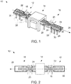
- a waterwall panel welding apparatus 10 includes an inlet assembly 12, a welding assembly 14, an outlet assembly 16, and a heating system 18, 20 that may include a preheating stage 18 and a PWHT stage 20.
- the inlet assembly 12 is configured to receive a plurality of tubes 22.
- the welding assembly 14 is configured to receive the tubes 22 from the inlet assembly 12, and is further configured to allow the tubes 22 to be welded together to form a waterwall panel 24.
- the waterwall panel 24 may be a high alloy panel, a low alloy panel, and/or other suitable panel/structure made from welded components.
- the outlet assembly 16 is configured to receive the waterwall panel 24 from the welding assembly 14.
- the heating system 18, 20 operates/heats via magnetic induction.
- the waterwall panel welding apparatus 10 may implement a conveyor / assembly line system, formed by the inlet assembly 12, the welding assembly 14, and the outlet assembly 16, that has a flow path (generally represented by arrow 26) in the direction from the inlet assembly 12 to the outlet assembly 16.
- the inlet assembly 12 is upstream of the welding assembly 14, while the outlet assembly 16 is downstream of the welding assembly 14.
- the waterwall welding apparatus 10 may be of a twelve torch, four torch, or gantry design.
- the term "twelve torch design” refers to a waterwall panel welding apparatus design wherein the welding assembly 14 provides for the ability to simultaneously weld multiple sites to combine independent tubes 22, i.e., tubes 22 not already forming part of an existing panel 24 or subpanel, into a single panel 24 fabrication, e.g., a welding apparatus capable of welding thirteen (13) tubes together via twelve (12) welding sites to form a single panel 24 and/or subpanel;
- the term “four torch design” refers to a waterwall panel welding apparatus design that provides for the ability to weld multiple subpanels into a larger panel 24;
- the term “gantry design” refers to a waterwall panel welding apparatus design wherein the tubes 22 remain stationary during welding, as opposed to moving along a conveyor / assembly line 26, while a gantry moves over the tubes 22.
- the heating system 18, 20 may be disposed an the gantry such that it moves with the gantry in relation to stationary tubes 22.
- the welding apparatus 10 may combine various features of the twelve torch, twelve torch, gantry, and/or other commonly used waterwall panel welding apparatus designs.
- the inlet assembly 12 may form the beginning/start of the flow path / assembly line 26.
- the inlet assembly 12 may include one or more rollers 28 supported by one or more supporting structures 30 so as to allow the tubes 22 to be longitudinally aligned into the shape of the panel 24 prior to being welded in the welding assembly 14.
- the components of the heating system 18 may be disposed on/in the inlet assembly 12 so as to preheat the tubes 22 prior to being welded in the welding assembly 14.
- the welding assembly 14 provides the necessary support, environment, and/or other equipment to facilitate welding of the tubes 22 to form the panel 24.
- the welding assembly 14 may also include supports and rollers (not shown) so as to allow the tubes 22 to enter the welding assembly 14 from the inlet assembly 12.
- the outlet assembly 16 may include supports 28 and rollers 30 that allow the freshly welded panel 24 to leave the welding assembly 14.
- the components of the heating system 20 may be disposed on/in the outlet assembly 16 so as to PHWT the tubes.
- inlet assembly 12, welding assembly 14, and outlet assembly 16 are described herein as utilizing supports 28 and rollers 30, it is to be understood that the inlet assembly 12, welding assembly 14, and/or outlet assembly 16 may utilize other structures capable of facilitating movement of the tubes 22 along the flow path / assembly line 26.
- a heating system 32 representative of the preheat stage 18 and/or the PWHT stage 20 of FIGS. 1 and 2 , is shown in relation to a plurality of tubes 22.
- the heating system 32 may include a heating inductor 34, a power supply 36, a controller 38, one or more sensors 39, and may be configured to heat the tubes 22 via magnetic induction.
- the power supply 36 may be in electronic communication with the heating inductor 34 so as to supply an electrical current, which may be an alternating current ("AC"), that passes through the heating inductor 34 to generate a magnetic field.
- AC alternating current
- the controller 38 may include at least one processor 40 and a memory device 42 that may store a welding application.
- the controller 38 may be in electronic communication with the power supply 36, and one or more power regulating devices (not shown), such that the controller 38 can manipulate/control the magnetic field generated by the heating inductor 34 via controlling/manipulating the flow of electricity through the heating inductor 34.
- the controller 38 may adjust the power supplied (electrical current) to the heating inductor 34 in an analog fashion.
- some embodiments of the controller 38 provide just enough power to the heating inductor 34 to maintain a particular temperature profile within the tubes 22.
- the one or more temperature sensors 39 may be in electronic communication with the controller 38 and configured to sense/detect the temperature of the tubes 22 so as to form a real-time and/or near real-time control/feedback loop.
- the temperature sensors 39 may take the form of optical sensors, e.g., infrared ("IR") cameras, LASERS, thermacouples, and/or other types of temperature sensing devices.
- each of the tubes 22 may include a longitudinal center axis 44, an outer diameter 46, and an inner diameter 48.
- One or more fins 50 may be attached to the outer diameter 46 at outer 52 and inner 54 joints.
- the tubes 22 may be welded together via the fins 50 so as to form the panel 24. While the tubes 22 are depicted as circular, it is to be understood that the tubes 22 may take other forms, e.g., squares, triangles, and/or other shapes capable of being welded together to form a larger object, e.g., a panel 24.
- the tubes 22 Prior to being welded together, the tubes 22 are longitudinally aligned, i.e., the longitudinal center axes 44 are aligned, so that the tubes 22 form the shape of the panel 24 prior to actually being welded.
- the fins 50 and the outer diameters 46 define/form peaks 56 and valleys 58, respectively, an both a first side 60 and a second side 62 of the pre-welded panel 24.
- the first 60 and the second 62 sides of the tubes 22/panel 24 are shown in FIG. 3 as being symmetrical, in other embodiments, the first 60 and the second 62 sides may be asymmetrical.
- the heating inductor 34 is configured to apply a magnetic field to the tubes 22 so as to induce an electrical current within the tubes 22.
- the heating inductor 34 may be a straight bar inductor as shown in FIG. 3 , or a coil inductor that wraps around the inlet 12 and/or the outlet 16 assemblies as shown in FIG. 1 .
- the heating inductor 34 is spaced apart from the outer diameters 46/peaks 56 of the tubes 22 and the fins 50/valleys 58 so as to define one or more gaps 64 and 66.
- the gap 64 between the heating inductor 34 and the peaks 56 is referred to herein as the "tube gap,” and the gap 66 between the heating inductor 34 and the valleys 58 is referred to herein as the "air gap”.
- the tube gap 64 and the air gap 66 may be 6.35-38.1 mm (.25-1.5 inches) and 6.35-25.4 mm (.25-1 inches), respectively.
- magnetic induction provides for the non-contact heating of a paramagnetic material via the generation/inducement of an electrical current within the paramagnetic material resulting from an applied magnetic field. Accordingly, the magnetic field generated by the heating inductor 34 induces electrical eddy currents within the tubes 22, which in turn results in subsurface heating of the tubes 22. As will be appreciated, subsurface heating is more efficient than contact surface heating, e.g., gas torches, as less heat escapes the tubes 22.
- the depth and/or intensity of the site of heating within the tubes 22 resulting from the magnetic field applied by the heating inductor 34 can be varied by varying the frequency of the electrical current passing through the heating inductor 34. For example, one can utilize high frequencies, e.g., 50 kHz, to heat regions within the tubes 22 closes to the surface/outer diameter 46, and/or low-frequencies, e.g., 60 kHz to heat regions deep within the tubes 22, e.g., up to 3 mm (1/8") from the surface/outer diameter 46.
- high frequencies e.g., 50 kHz
- low-frequencies e.g. 60 kHz
- the heating inductor 34 may apply a static magnetic field over an extended period of time, e.g., five (5) seconds, and/or apply a series of magnetic pulses to the tubes 22, e.g., applying a series of magnetic pulses over a ten (10) second period, each pulse having a duration of one (1) second, and subsequent pulses spaced apart by a duration less than one (1) second.
- a static magnetic field e.g., five (5) seconds
- a series of magnetic pulses e.g., applying a series of magnetic pulses over a ten (10) second period, each pulse having a duration of one (1) second, and subsequent pulses spaced apart by a duration less than one (1) second.
- the period, duration of each pulse, and the duration between subsequent pulses may be varied in embodiments to achieve a desired temperature profile.
- the heating inductor 34 may heat the tubes 22 up to a temperature between and including 302° F (150° C) to 400° F (200° C) when utilized in the preheating stage 18, and/or between and including 1,292° F (700° C) to 1,445° F (785° C) when utilized in the PWHT stage 20.
- the depth and/or intensity of the site of heating within the tubes 22 resulting from the magnetic field applied by the heating inductor 34 is varied, according to the present invention, by varying the tube gap 64 and/or the air gap 66.
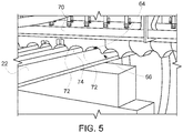
- the heating inductor (34 FIG. 3 ) is, according to the present invention, a shaped inductive heater (70 in FIGS. 4 and 5 ).
- the shaped inductive heater 70 conforms to the shape of the tubes 22 such that tube gap 64 and/or the air gap 66 is reduced when compared to a straight bar inductor.
- the shaped inductive heater 70 may include one or more raised portions 72 and one or more wells 74. As best seen in FIG.
- the wells 74 may have a square, circular, or other shaped profile, and may further have a max chord 76, i.e., the longest cord across the profile of a well 74 from raised portion 72 to raised portion 72, and/or a radius 78.
- the raised portions 72 and/or the wells 74 may be arranged such that they matchingly align with the valleys 58 and/or the peaks 56, respectively.
- the terms “matchingly align”, “matchingly alining”, and “matching alignment” mean that the raised portions 72 and the wells 74 are generally arranged over the valleys 58 and/or the peaks 56, respectively, and as shown by the dashed lines 79 in FIG. 4 , such that the profile formed by the shaped inductive heater 70 fits over/around the tubes 22 as shown in FIG. 5 .
- the raised portions 72 may be configured to penetrate/extend into the valleys 58, e.g., the tips of the raised portions 72 are below the tips of the peaks 56.
- the raised portions may include and/or be formed from an alloyed magnetic ceramic material.
- the raised portions 72 and/or the wells 74 may be mechanically manipulated such that the spacing of the raised portions 72 and/or wells 74 may be adjusted to conform to pipes 22 of various sizes and/or various spacing, i.e., the space between subsequent peaks 56 and valleys 58.
- the raised portions 72 and/or the wells 74 may be mechanically manipulated/adjusted such that the max cord 76 and/or the radius 78 changes.
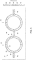
- FIG. 6 depicts the temperature gradient, represented as a temperature percentage, of the tubes 22 and fins 50 resulting from the magnetic flux produced by the shaped inductive heater 70.
- straight bar inductors e.g., non-shaped inductive heaters, typically produce a uniform/flat magnetic field which may result in non-uniform heating of the tubes 22, i.e., the peaks 56 of the tubes 22 are heated at a greater intensity than the valleys 58/fins 50.
- the shaped inductive heater 70 produces a shaped magnetic field ( FIG. 6 ), which in turn results in a more uniform heating of the tubes 22 (shown in FIG. 7 by the dose tracking of the "fin temperature”, e.g., the temperature of the valleys 58, to the "tube temperature”, e.g., the temperature of the tubes 22 in the regions between the internal 48 and the external 46 diameters).
- the shaped inductive heater 70 reduces the difference in heating intensities between the peaks 56 and the valleys 58 compared to a straight bar inductor.
- the shaped inductive heater 70 focuses electromagnetic flux onto an object, e.g., panel 24 having a shape defined by the tubes 22 and fins 50, such that the shape of the induced magnetic flux / magnetic field better conforms to the shape of the object being heated.
- FIG. 8 a method 80 of welding a plurality of tubes 22 together to form a waterwall panel 24 that utilizes the apparatus 10 is shown.
- the welding application stored in the memory device 42 may be loaded into the at least one processor/CPU 40 such that the controller 38 is further adapted/configured by the heating application to perform all, or part, of method 80.
- the method 80 includes longitudinally aligning 82 the tubes 22, welding 84 the tubes 22 to each other to form the waterwall panel 24, and heating 86 and/or 88 the tubes 22 via magnetic induction. Welding 84 the tubes may be synchronized with the speed of the assembly line/conveyor 26.
- heating 86/88 the tubes 22 via magnetic induction may preheat 86 the tubes 22 before the tubes 22 are welded together to form the waterwall panel 24, and/or PWHT 88 the tubes 22.
- Heating 86/88 the tubes includes, according to the present invention, aligning 90 the raised portions 72 and/or the wells 74 with a corresponding valley 58 and/or a peak 56, respectively.
- the method 86 may further include cooling 92 the tubes 22 prior to PWHT 88.
- the welding apparatus 10 may include one or more cooling devices, e.g., fans, blowers, and/or other suitable cooling devices, configured to cool the tubes 22 to a martensitic transformation finish temperature prior to undergoing PWHT 88.
- heating 86/88 the tubes 22 via magnetic induction may include applying 94 a static magnetic field to the tubes 22 for an extended period of time; and/or applying 96 a series of magnetic pulses to the tubes 22.
- the apparatus 10 may include the necessary electronics, software, memory, storage, databases, firmware, logic/state machines, microprocessors, communication links, displays or other visual or audio user interfaces, printing devices, and any other input/output interfaces to perform the functions described herein and/or to achieve the results described herein.
- the apparatus 10 may include at least one processor 40, and system memory 42, which may include random access memory (RAM) and read-only memory (ROM).
- the apparatus 10 may further include an input/output controller, and one or more data storage structures. All of these latter elements may be in communication with the at least one processor 40 to facilitate the Operation of the apparatus 10 as discussed above.
- Suitable computer program code may be provided for executing numerous functions, including those discussed above in connection with the apparatus 10 and method 80 disclosed herein.
- the computer program code may also include program elements such as an operating system, a database management system and "device drivers" that allow the apparatus 10, to interface with computer peripheral devices, e.g., sensors, a video display, a keyboard, a computer mouse, etc.
- the at least one processor 40 of the apparatus 10 may include one or more conventional microprocessors and one or more supplementary co-processors such as math co-processors or the like. Elements in communication with each other need not be continually signaling or transmitting to each other. On the contrary, such elements may transmit to each other as necessary, may refrain from exchanging data at certain times, and may cause several steps to be performed to establish a communication link therebetween.
- the data storage structures such as memory discussed herein may include an appropriate combination of magnetic, optical and/or semiconductor memory, and may include, for example, RAM, ROM, flach drive, an optical disc such as a compact disc and/or a hard disk or drive.
- the data storage structures may store, for example, information required by the apparatus 10 and/or one or more programs, e.g., computer program code such as the welding application stored in memory device 42 and/or other computer program product, adapted to direct the apparatus 10.
- the programs may be stored, for example, in a compressed, an uncompiled and/or an encrypted format, and may include computer program code.
- the instructions of the computer program code may be read into a main memory of a processor from a computer-readable medium.
- the program may also be implemented in programmable hardware devices such as field programmable gate arrays, programmable array logic, programmable logic devices or the like. Programs may also be implemented in software for execution by various types of computer processors.
- a program of executable code may, for instance, include one or more physical or logical blocks of computer instructions, which may, for instance, be organized as an object, procedure, process or function. Nevertheless, the executables of an identified program need not be physically located together, but may include separate instructions stored in different locations which, when joined logically together, form the program and achieve the stated purpose for the programs such as preserving privacy by executing the plurality of random operations.
- an application of executable code may be a compilation of mang instructions, and may even be distributed over several different code partitions or segments, among different programs, and across several devices.
- Non-volatile media include, for example, optical, magnetic, or opto-magnetic disks, such as memory.
- Volatile media include dynamic random access memory (DRAM), which typically constitutes the main memory.
- Computer-readable media include, for example, a floppy disk, a flexible disk, hard disk, magnetic tape, any other magnetic medium, a CD-ROM, DVD, any other optical medium, a RAM, a PROM, an EPROM or EEPROM (electronically erasable programmable read-only memory), a FLASH-EEPROM, any other memory chip or cartridge, or any other medium from which a computer can read.
- Various forms of computer readable media may be involved in carrying one or more sequences of one or more instructions to at least one processor for execution.
- the instructions may initially be borne on a magnetic disk of a remote computer (not shown).
- the remote computer can load the instructions into its dynamic memory and send the instructions over an Ethernet connection, cable line, or telephone line using a modem.
- a communications device local to a computing device e.g., a server, can receive the data on the respective communications line and place the data on a system bus for at least one processor.
- the system bus carries the data to main memory, from which the at least one processor retrieves and executes the instructions.
- the instructions received by main memory may optionally be stored in memory either before or after execution by the at least one processor.
- instructions may be received via a communication port as electrical, electromagnetic or optical signals, which are exemplary forms of wireless communications or data streams that carry various types of information.
- the power supply may be 92% efficient and the heating inductor may be 80% or more efficient. Thus, some embodiments may only require a 40-amp line to produce 25 kW of power.
- some embodiments provide that the heating inductor does not itself become excessively hot.
- such embodiments may provide for increased operational safety over conventional contact heaters, avoid contamination of the welded components resulting from atoms of the such contact heaters adhering to the welded material, and/or reduce the amount of dust generated due to vaporization of insulation blankets and/or other materials.
- the inductive heaters of some embodiments may heat the tubes up to four times faster than traditional contact heaters, thus providing for further reductions in the cycle production time of individual panels.
Landscapes
- Engineering & Computer Science (AREA)
- Physics & Mathematics (AREA)
- Mechanical Engineering (AREA)
- Chemical & Material Sciences (AREA)
- Thermal Sciences (AREA)
- General Engineering & Computer Science (AREA)
- Metallurgy (AREA)
- Electromagnetism (AREA)
- Crystallography & Structural Chemistry (AREA)
- Materials Engineering (AREA)
- Organic Chemistry (AREA)
- Optics & Photonics (AREA)
- Plasma & Fusion (AREA)
- General Induction Heating (AREA)
- Heat Treatment Of Articles (AREA)
- Lining Or Joining Of Plastics Or The Like (AREA)
Claims (7)
- Procédé de soudage d'une pluralité de tubes (22) ensemble pour former un panneau écran d'eau (24), le procédé comprenant :l'alignement longitudinal des tubes (22) ;le soudage des tubes (22) les uns aux autres pour former le panneau écran d'eau (24) ;le chauffage du ou des tubes (22) par induction magnétique ;et étant caractérisé par les étapes suivantes :l'alignement d'une ou plusieurs parties surélevées (72) d'un chauffage par induction profilé (32) de telle sorte que chaque partie surélevée (72) concorde avec une vallée correspondante (58) définie par une ou plusieurs ailettes (50) des tubes (22), la variation de la profondeur et/ou de l'intensité du site de chauffage au sein des tubes (22) résultant du champ magnétique appliqué par l'inducteur de chauffage (34) espacés de diamètres externes (46), étant également définis ou formés en tant que pics (56), des tubes (22) et des ailettes (50), étant définis ou formés en tant que vallées (58), en faisant varier un espace de tube (64) entre l'inducteur de chauffage (34) et les pics (56) et/ou un espace d'air (66) défini entre l'inducteur de chauffage (34) et les vallées (58).
- Procédé selon la revendication 1, dans lequel le chauffage du ou des tubes par induction magnétique préchauffe les tubes (22) avant que les tubes soient soudés ensemble pour former le panneau écran d'eau (24).
- Procédé selon la revendication 1 ou 2, dans lequel le chauffage du ou des tubes (22) par induction magnétique traite thermiquement après soudage les tubes (22) et dans lequel le chauffage du ou des tubes (22) par induction magnétique pour traiter thermiquement après soudage les tubes (22) est mis en œuvre sur un appareil de soudage (14).
- Procédé selon l'une quelconque des revendications 1 à 3, dans lequel le procédé comprend en outre : le refroidissement des tubes (22).
- Procédé selon l'une quelconque des revendications 1 à 4, dans lequel le chauffage du ou des tubes (22) par induction magnétique comprend :
l'application d'un champ magnétique statique aux tubes (22) pendant une période de temps prolongée. - Procédé selon l'une quelconque des revendications 1 à 5, dans lequel le chauffage du ou des tubes (22) par induction magnétique comprend :
l'application d'une série d'impulsions magnétiques aux tubes (22). - Procédé selon l'une quelconque des revendications 1 à 6, dans lequel le chauffage du ou des tubes (22) par induction magnétique comprend l'utilisation d'un courant alternatif qui a au moins l'une parmi une haute fréquence qui chauffe une ou plusieurs régions pratiquement en surface des tubes (22), et une basse fréquence qui chauffe une ou plusieurs régions profondes des tubes (22).
Priority Applications (1)
| Application Number | Priority Date | Filing Date | Title |
|---|---|---|---|
| PL17726881T PL3463814T3 (pl) | 2016-06-03 | 2017-05-19 | Sposób indukcyjnego spawania panelu ekranowego |
Applications Claiming Priority (2)
| Application Number | Priority Date | Filing Date | Title |
|---|---|---|---|
| US15/172,430 US10731849B2 (en) | 2016-06-03 | 2016-06-03 | Apparatus and method for welding a waterwall panel |
| PCT/EP2017/062127 WO2017207302A1 (fr) | 2016-06-03 | 2017-05-19 | Appareil et procédé de soudage d'un panneau d'écran d'eau |
Publications (2)
| Publication Number | Publication Date |
|---|---|
| EP3463814A1 EP3463814A1 (fr) | 2019-04-10 |
| EP3463814B1 true EP3463814B1 (fr) | 2021-09-15 |
Family
ID=58873788
Family Applications (1)
| Application Number | Title | Priority Date | Filing Date |
|---|---|---|---|
| EP17726881.0A Not-in-force EP3463814B1 (fr) | 2016-06-03 | 2017-05-19 | Procédé de soudage par induction magnétique d'une paroi d'eau |
Country Status (8)
| Country | Link |
|---|---|
| US (1) | US10731849B2 (fr) |
| EP (1) | EP3463814B1 (fr) |
| JP (1) | JP6997723B2 (fr) |
| CN (1) | CN109475970B (fr) |
| MX (1) | MX2018014855A (fr) |
| PL (1) | PL3463814T3 (fr) |
| TW (1) | TWI729137B (fr) |
| WO (1) | WO2017207302A1 (fr) |
Families Citing this family (9)
| Publication number | Priority date | Publication date | Assignee | Title |
|---|---|---|---|---|
| US11286536B2 (en) * | 2019-08-06 | 2022-03-29 | General Electric Company | System and method for manufacturing a part |
| CN110640315A (zh) * | 2019-08-26 | 2020-01-03 | 江苏大学 | 一种外加变频磁场的激光焊接方法和装置 |
| CN110814485B (zh) * | 2019-11-26 | 2021-10-15 | 江苏鑫上电子科技有限公司 | 一种双轴光伏支架的光伏安装板焊接设备 |
| CN111633367B (zh) * | 2020-04-13 | 2024-01-19 | 武汉船用机械有限责任公司 | 用于燃气轮机引气支柱的焊接装置及焊接方法 |
| CN111571051B (zh) * | 2020-05-06 | 2022-04-01 | 徐州徐工基础工程机械有限公司 | 一种旋挖钻钻杆外键焊前预热和焊后热处理系统及方法 |
| CN112361444A (zh) * | 2020-10-27 | 2021-02-12 | 安徽佳暖节能科技有限公司 | 一种用于取暖设备的加热管装置的加工工艺 |
| CN112792534B (zh) * | 2021-01-26 | 2025-08-15 | 上海豪德热能科技有限公司 | 蛇形管屏组装系统及应用该组装系统的蛇形管屏组装方法 |
| CN115106705B (zh) * | 2022-08-30 | 2022-11-04 | 中国能源建设集团山西电力建设有限公司 | 两水冷壁鳍片式管排组件的成组对接焊接定位方法 |
| CN117102649B (zh) * | 2023-09-28 | 2025-01-28 | 四川旷世达金属制品有限公司 | 用于金属复合管的感应焊接装置及其方法 |
Family Cites Families (21)
| Publication number | Priority date | Publication date | Assignee | Title |
|---|---|---|---|---|
| US3467809A (en) | 1966-11-18 | 1969-09-16 | Combustion Eng | Welding apparatus for forming panels of tubes |
| JPS589786A (ja) | 1981-07-08 | 1983-01-20 | Hitachi Ltd | 配管系の溶接部の熱処理方法 |
| JP2819778B2 (ja) * | 1989-08-07 | 1998-11-05 | 株式会社明電舎 | 高周波電縫管溶接装置 |
| AU738294B2 (en) * | 1997-07-30 | 2001-09-13 | Fosbel International Limited | High frequency induction fusing |
| US6091063A (en) | 1998-11-06 | 2000-07-18 | The Boeing Company | Method for improving thermal uniformity in induction heating processes |
| JP2000329304A (ja) * | 1999-05-21 | 2000-11-30 | Dai Ichi High Frequency Co Ltd | 水冷パネルセグメントの加熱方法 |
| US6852945B2 (en) * | 2002-06-19 | 2005-02-08 | The Babcock & Wilcox Company | Laser welding boiler tube wall panels |
| US7028882B2 (en) | 2004-02-02 | 2006-04-18 | General Electric Company | Process and apparatus for boiler tube panel welding and straightening |
| JP4411114B2 (ja) * | 2004-03-24 | 2010-02-10 | 第一高周波工業株式会社 | 合金被覆ボイラ部品、及び自溶合金被覆ボイラ部品の溶接施工方法 |
| JP4297354B2 (ja) | 2004-05-28 | 2009-07-15 | 第一高周波工業株式会社 | ボイラパネル加熱装置および方法 |
| CN100464924C (zh) * | 2004-06-30 | 2009-03-04 | 上海锅炉厂有限公司 | 锅炉膜式管屏管排脉冲埋弧焊工艺 |
| US20060132045A1 (en) * | 2004-12-17 | 2006-06-22 | Baarman David W | Heating system and heater |
| JP2008116150A (ja) | 2006-11-06 | 2008-05-22 | Dai Ichi High Frequency Co Ltd | ボイラ水壁用パネル |
| DE102008037085B3 (de) * | 2008-08-08 | 2009-08-06 | Alstom Technology Ltd. | Verfahren zur Herstellung von Dampferzeuger-Rohrwänden bestehend aus überwiegend 9-12% chromhaltigen, martensitischen Stählen |
| TWI346195B (en) * | 2009-03-06 | 2011-08-01 | Wen Chih Liao | Device and method for brazing a heat pipe |
| DE102011013094A1 (de) | 2011-03-04 | 2012-09-06 | Rwe Technology Gmbh | Verfahren zur Wärmebehandlung von Schweißnähten an Kraftwerks- und Anlagenbauteilen |
| US9451658B2 (en) * | 2011-05-10 | 2016-09-20 | Nordon Corporation | Induction oven for curing coatings on containers |
| JP5868619B2 (ja) * | 2011-06-21 | 2016-02-24 | ニチアス株式会社 | 熱処理炉及び熱処理装置 |
| CN104227255B (zh) * | 2014-07-23 | 2017-09-15 | 江苏海森电气科技有限公司 | 冷凝器排焊生产线 |
| CN104801834B (zh) * | 2014-08-14 | 2017-03-08 | 江苏绿叶锅炉有限公司 | T91水冷壁管排焊接工艺 |
| CN205147615U (zh) * | 2015-10-29 | 2016-04-13 | 吉林大学 | 螺旋板换热器自动焊接机 |
-
2016
- 2016-06-03 US US15/172,430 patent/US10731849B2/en active Active
-
2017
- 2017-05-19 JP JP2018562594A patent/JP6997723B2/ja active Active
- 2017-05-19 PL PL17726881T patent/PL3463814T3/pl unknown
- 2017-05-19 EP EP17726881.0A patent/EP3463814B1/fr not_active Not-in-force
- 2017-05-19 MX MX2018014855A patent/MX2018014855A/es unknown
- 2017-05-19 CN CN201780033676.2A patent/CN109475970B/zh not_active Expired - Fee Related
- 2017-05-19 WO PCT/EP2017/062127 patent/WO2017207302A1/fr not_active Ceased
- 2017-05-22 TW TW106116904A patent/TWI729137B/zh active
Also Published As
| Publication number | Publication date |
|---|---|
| TWI729137B (zh) | 2021-06-01 |
| JP6997723B2 (ja) | 2022-01-18 |
| WO2017207302A1 (fr) | 2017-12-07 |
| EP3463814A1 (fr) | 2019-04-10 |
| PL3463814T3 (pl) | 2022-01-10 |
| US20170350588A1 (en) | 2017-12-07 |
| CN109475970B (zh) | 2021-03-23 |
| JP2019534161A (ja) | 2019-11-28 |
| MX2018014855A (es) | 2019-05-22 |
| TW201808501A (zh) | 2018-03-16 |
| CN109475970A (zh) | 2019-03-15 |
| US10731849B2 (en) | 2020-08-04 |
Similar Documents
| Publication | Publication Date | Title |
|---|---|---|
| US10731849B2 (en) | Apparatus and method for welding a waterwall panel | |
| US20110248023A1 (en) | Induction heat treatment of an annular workpiece | |
| CN102482725A (zh) | 用于进行能量高效的热成型处理的方法和装置 | |
| CN105264097A (zh) | 热的、薄壁钢件的输送设备 | |
| JP7739259B2 (ja) | 部品を製造するためのシステムおよび方法 | |
| US10273551B2 (en) | Method for generating a stress reduction in erected tube walls of a steam generator | |
| US4500366A (en) | Process for producing a grain-oriented electromagnetic steel strip or sheet | |
| CN101636511A (zh) | 用于对延展钢制品进行热处理的方法 | |
| US2428303A (en) | Induction heating means for gear teeth | |
| JP5843456B2 (ja) | 熱処理装置及び熱処理方法 | |
| JP5272706B2 (ja) | 鉄粉の熱処理方法および装置 | |
| US20180258506A1 (en) | Heat treatment system | |
| JP7266426B2 (ja) | ワークの焼き戻し方法、及びこの方法で得られた機械部品 | |
| CN101578379B (zh) | 用于热处理焊缝的方法和装置 | |
| US20170041988A1 (en) | Apparatus and method for heating annular workpiece, and heating coil | |
| JP4353339B2 (ja) | 歯車の高周波輪郭焼入方法 | |
| Dietrich et al. | Investigation of geometrical discontinuities in blanks for hot sheet metal forming process under the influence of induction heating | |
| KR20150039652A (ko) | 불연속 히터를 사용한 열처리로 | |
| Rudnev | Reader asks,‘How do I select inductors for billet heating?’ | |
| JPH033728B2 (fr) | ||
| DE502005008414D1 (de) | Verfahren und vorrichtung zur wärmebehandlung eines brennelementkastens aus einer zirkoniumlegierung | |
| KR20080057509A (ko) | 연속 어닐링 장치의 복사 가열 장치 | |
| EP3177746A1 (fr) | Four de rechauffage pour barres metalliques | |
| JP2014020762A (ja) | 熱処理装置 | |
| JP2008070030A (ja) | 加熱炉 |
Legal Events
| Date | Code | Title | Description |
|---|---|---|---|
| STAA | Information on the status of an ep patent application or granted ep patent |
Free format text: STATUS: UNKNOWN |
|
| STAA | Information on the status of an ep patent application or granted ep patent |
Free format text: STATUS: THE INTERNATIONAL PUBLICATION HAS BEEN MADE |
|
| PUAI | Public reference made under article 153(3) epc to a published international application that has entered the european phase |
Free format text: ORIGINAL CODE: 0009012 |
|
| STAA | Information on the status of an ep patent application or granted ep patent |
Free format text: STATUS: REQUEST FOR EXAMINATION WAS MADE |
|
| 17P | Request for examination filed |
Effective date: 20190103 |
|
| AK | Designated contracting states |
Kind code of ref document: A1 Designated state(s): AL AT BE BG CH CY CZ DE DK EE ES FI FR GB GR HR HU IE IS IT LI LT LU LV MC MK MT NL NO PL PT RO RS SE SI SK SM TR |
|
| AX | Request for extension of the european patent |
Extension state: BA ME |
|
| DAV | Request for validation of the european patent (deleted) | ||
| DAX | Request for extension of the european patent (deleted) | ||
| STAA | Information on the status of an ep patent application or granted ep patent |
Free format text: STATUS: EXAMINATION IS IN PROGRESS |
|
| 17Q | First examination report despatched |
Effective date: 20200123 |
|
| GRAP | Despatch of communication of intention to grant a patent |
Free format text: ORIGINAL CODE: EPIDOSNIGR1 |
|
| STAA | Information on the status of an ep patent application or granted ep patent |
Free format text: STATUS: GRANT OF PATENT IS INTENDED |
|
| INTG | Intention to grant announced |
Effective date: 20210413 |
|
| RAP3 | Party data changed (applicant data changed or rights of an application transferred) |
Owner name: GENERAL ELECTRIC TECHNOLOGY GMBH |
|
| GRAS | Grant fee paid |
Free format text: ORIGINAL CODE: EPIDOSNIGR3 |
|
| GRAA | (expected) grant |
Free format text: ORIGINAL CODE: 0009210 |
|
| STAA | Information on the status of an ep patent application or granted ep patent |
Free format text: STATUS: THE PATENT HAS BEEN GRANTED |
|
| AK | Designated contracting states |
Kind code of ref document: B1 Designated state(s): AL AT BE BG CH CY CZ DE DK EE ES FI FR GB GR HR HU IE IS IT LI LT LU LV MC MK MT NL NO PL PT RO RS SE SI SK SM TR |
|
| REG | Reference to a national code |
Ref country code: CH Ref legal event code: EP |
|
| REG | Reference to a national code |
Ref country code: DE Ref legal event code: R096 Ref document number: 602017046031 Country of ref document: DE |
|
| REG | Reference to a national code |
Ref country code: IE Ref legal event code: FG4D |
|
| REG | Reference to a national code |
Ref country code: AT Ref legal event code: REF Ref document number: 1430197 Country of ref document: AT Kind code of ref document: T Effective date: 20211015 |
|
| REG | Reference to a national code |
Ref country code: LT Ref legal event code: MG9D |
|
| REG | Reference to a national code |
Ref country code: NL Ref legal event code: MP Effective date: 20210915 |
|
| PG25 | Lapsed in a contracting state [announced via postgrant information from national office to epo] |
Ref country code: SE Free format text: LAPSE BECAUSE OF FAILURE TO SUBMIT A TRANSLATION OF THE DESCRIPTION OR TO PAY THE FEE WITHIN THE PRESCRIBED TIME-LIMIT Effective date: 20210915 Ref country code: RS Free format text: LAPSE BECAUSE OF FAILURE TO SUBMIT A TRANSLATION OF THE DESCRIPTION OR TO PAY THE FEE WITHIN THE PRESCRIBED TIME-LIMIT Effective date: 20210915 Ref country code: HR Free format text: LAPSE BECAUSE OF FAILURE TO SUBMIT A TRANSLATION OF THE DESCRIPTION OR TO PAY THE FEE WITHIN THE PRESCRIBED TIME-LIMIT Effective date: 20210915 Ref country code: NO Free format text: LAPSE BECAUSE OF FAILURE TO SUBMIT A TRANSLATION OF THE DESCRIPTION OR TO PAY THE FEE WITHIN THE PRESCRIBED TIME-LIMIT Effective date: 20211215 Ref country code: FI Free format text: LAPSE BECAUSE OF FAILURE TO SUBMIT A TRANSLATION OF THE DESCRIPTION OR TO PAY THE FEE WITHIN THE PRESCRIBED TIME-LIMIT Effective date: 20210915 Ref country code: LT Free format text: LAPSE BECAUSE OF FAILURE TO SUBMIT A TRANSLATION OF THE DESCRIPTION OR TO PAY THE FEE WITHIN THE PRESCRIBED TIME-LIMIT Effective date: 20210915 Ref country code: BG Free format text: LAPSE BECAUSE OF FAILURE TO SUBMIT A TRANSLATION OF THE DESCRIPTION OR TO PAY THE FEE WITHIN THE PRESCRIBED TIME-LIMIT Effective date: 20211215 |
|
| REG | Reference to a national code |
Ref country code: AT Ref legal event code: MK05 Ref document number: 1430197 Country of ref document: AT Kind code of ref document: T Effective date: 20210915 |
|
| PG25 | Lapsed in a contracting state [announced via postgrant information from national office to epo] |
Ref country code: LV Free format text: LAPSE BECAUSE OF FAILURE TO SUBMIT A TRANSLATION OF THE DESCRIPTION OR TO PAY THE FEE WITHIN THE PRESCRIBED TIME-LIMIT Effective date: 20210915 Ref country code: GR Free format text: LAPSE BECAUSE OF FAILURE TO SUBMIT A TRANSLATION OF THE DESCRIPTION OR TO PAY THE FEE WITHIN THE PRESCRIBED TIME-LIMIT Effective date: 20211216 |
|
| PG25 | Lapsed in a contracting state [announced via postgrant information from national office to epo] |
Ref country code: AT Free format text: LAPSE BECAUSE OF FAILURE TO SUBMIT A TRANSLATION OF THE DESCRIPTION OR TO PAY THE FEE WITHIN THE PRESCRIBED TIME-LIMIT Effective date: 20210915 |
|
| PG25 | Lapsed in a contracting state [announced via postgrant information from national office to epo] |
Ref country code: IS Free format text: LAPSE BECAUSE OF FAILURE TO SUBMIT A TRANSLATION OF THE DESCRIPTION OR TO PAY THE FEE WITHIN THE PRESCRIBED TIME-LIMIT Effective date: 20220115 Ref country code: SM Free format text: LAPSE BECAUSE OF FAILURE TO SUBMIT A TRANSLATION OF THE DESCRIPTION OR TO PAY THE FEE WITHIN THE PRESCRIBED TIME-LIMIT Effective date: 20210915 Ref country code: SK Free format text: LAPSE BECAUSE OF FAILURE TO SUBMIT A TRANSLATION OF THE DESCRIPTION OR TO PAY THE FEE WITHIN THE PRESCRIBED TIME-LIMIT Effective date: 20210915 Ref country code: RO Free format text: LAPSE BECAUSE OF FAILURE TO SUBMIT A TRANSLATION OF THE DESCRIPTION OR TO PAY THE FEE WITHIN THE PRESCRIBED TIME-LIMIT Effective date: 20210915 Ref country code: PT Free format text: LAPSE BECAUSE OF FAILURE TO SUBMIT A TRANSLATION OF THE DESCRIPTION OR TO PAY THE FEE WITHIN THE PRESCRIBED TIME-LIMIT Effective date: 20220117 Ref country code: NL Free format text: LAPSE BECAUSE OF FAILURE TO SUBMIT A TRANSLATION OF THE DESCRIPTION OR TO PAY THE FEE WITHIN THE PRESCRIBED TIME-LIMIT Effective date: 20210915 Ref country code: ES Free format text: LAPSE BECAUSE OF FAILURE TO SUBMIT A TRANSLATION OF THE DESCRIPTION OR TO PAY THE FEE WITHIN THE PRESCRIBED TIME-LIMIT Effective date: 20210915 Ref country code: EE Free format text: LAPSE BECAUSE OF FAILURE TO SUBMIT A TRANSLATION OF THE DESCRIPTION OR TO PAY THE FEE WITHIN THE PRESCRIBED TIME-LIMIT Effective date: 20210915 Ref country code: AL Free format text: LAPSE BECAUSE OF FAILURE TO SUBMIT A TRANSLATION OF THE DESCRIPTION OR TO PAY THE FEE WITHIN THE PRESCRIBED TIME-LIMIT Effective date: 20210915 |
|
| REG | Reference to a national code |
Ref country code: DE Ref legal event code: R097 Ref document number: 602017046031 Country of ref document: DE |
|
| PLBE | No opposition filed within time limit |
Free format text: ORIGINAL CODE: 0009261 |
|
| STAA | Information on the status of an ep patent application or granted ep patent |
Free format text: STATUS: NO OPPOSITION FILED WITHIN TIME LIMIT |
|
| PG25 | Lapsed in a contracting state [announced via postgrant information from national office to epo] |
Ref country code: DK Free format text: LAPSE BECAUSE OF FAILURE TO SUBMIT A TRANSLATION OF THE DESCRIPTION OR TO PAY THE FEE WITHIN THE PRESCRIBED TIME-LIMIT Effective date: 20210915 |
|
| 26N | No opposition filed |
Effective date: 20220616 |
|
| PG25 | Lapsed in a contracting state [announced via postgrant information from national office to epo] |
Ref country code: SI Free format text: LAPSE BECAUSE OF FAILURE TO SUBMIT A TRANSLATION OF THE DESCRIPTION OR TO PAY THE FEE WITHIN THE PRESCRIBED TIME-LIMIT Effective date: 20210915 |
|
| REG | Reference to a national code |
Ref country code: DE Ref legal event code: R119 Ref document number: 602017046031 Country of ref document: DE |
|
| REG | Reference to a national code |
Ref country code: CH Ref legal event code: PL |
|
| REG | Reference to a national code |
Ref country code: BE Ref legal event code: MM Effective date: 20220531 |
|
| GBPC | Gb: european patent ceased through non-payment of renewal fee |
Effective date: 20220519 |
|
| PG25 | Lapsed in a contracting state [announced via postgrant information from national office to epo] |
Ref country code: MC Free format text: LAPSE BECAUSE OF FAILURE TO SUBMIT A TRANSLATION OF THE DESCRIPTION OR TO PAY THE FEE WITHIN THE PRESCRIBED TIME-LIMIT Effective date: 20210915 Ref country code: LU Free format text: LAPSE BECAUSE OF NON-PAYMENT OF DUE FEES Effective date: 20220519 Ref country code: LI Free format text: LAPSE BECAUSE OF NON-PAYMENT OF DUE FEES Effective date: 20220531 Ref country code: IT Free format text: LAPSE BECAUSE OF FAILURE TO SUBMIT A TRANSLATION OF THE DESCRIPTION OR TO PAY THE FEE WITHIN THE PRESCRIBED TIME-LIMIT Effective date: 20210915 Ref country code: CH Free format text: LAPSE BECAUSE OF NON-PAYMENT OF DUE FEES Effective date: 20220531 |
|
| PG25 | Lapsed in a contracting state [announced via postgrant information from national office to epo] |
Ref country code: IE Free format text: LAPSE BECAUSE OF NON-PAYMENT OF DUE FEES Effective date: 20220519 Ref country code: FR Free format text: LAPSE BECAUSE OF NON-PAYMENT OF DUE FEES Effective date: 20220531 |
|
| PG25 | Lapsed in a contracting state [announced via postgrant information from national office to epo] |
Ref country code: GB Free format text: LAPSE BECAUSE OF NON-PAYMENT OF DUE FEES Effective date: 20220519 Ref country code: DE Free format text: LAPSE BECAUSE OF NON-PAYMENT OF DUE FEES Effective date: 20221201 Ref country code: BE Free format text: LAPSE BECAUSE OF NON-PAYMENT OF DUE FEES Effective date: 20220531 |
|
| P01 | Opt-out of the competence of the unified patent court (upc) registered |
Effective date: 20230523 |
|
| PGFP | Annual fee paid to national office [announced via postgrant information from national office to epo] |
Ref country code: CZ Payment date: 20230421 Year of fee payment: 7 |
|
| PGFP | Annual fee paid to national office [announced via postgrant information from national office to epo] |
Ref country code: PL Payment date: 20230420 Year of fee payment: 7 |
|
| PG25 | Lapsed in a contracting state [announced via postgrant information from national office to epo] |
Ref country code: HU Free format text: LAPSE BECAUSE OF FAILURE TO SUBMIT A TRANSLATION OF THE DESCRIPTION OR TO PAY THE FEE WITHIN THE PRESCRIBED TIME-LIMIT; INVALID AB INITIO Effective date: 20170519 |
|
| PG25 | Lapsed in a contracting state [announced via postgrant information from national office to epo] |
Ref country code: MK Free format text: LAPSE BECAUSE OF FAILURE TO SUBMIT A TRANSLATION OF THE DESCRIPTION OR TO PAY THE FEE WITHIN THE PRESCRIBED TIME-LIMIT Effective date: 20210915 Ref country code: CY Free format text: LAPSE BECAUSE OF FAILURE TO SUBMIT A TRANSLATION OF THE DESCRIPTION OR TO PAY THE FEE WITHIN THE PRESCRIBED TIME-LIMIT Effective date: 20210915 |
|
| PG25 | Lapsed in a contracting state [announced via postgrant information from national office to epo] |
Ref country code: TR Free format text: LAPSE BECAUSE OF FAILURE TO SUBMIT A TRANSLATION OF THE DESCRIPTION OR TO PAY THE FEE WITHIN THE PRESCRIBED TIME-LIMIT Effective date: 20210915 |
|
| PG25 | Lapsed in a contracting state [announced via postgrant information from national office to epo] |
Ref country code: MT Free format text: LAPSE BECAUSE OF FAILURE TO SUBMIT A TRANSLATION OF THE DESCRIPTION OR TO PAY THE FEE WITHIN THE PRESCRIBED TIME-LIMIT Effective date: 20210915 |
|
| PG25 | Lapsed in a contracting state [announced via postgrant information from national office to epo] |
Ref country code: CZ Free format text: LAPSE BECAUSE OF NON-PAYMENT OF DUE FEES Effective date: 20240519 |
|
| PG25 | Lapsed in a contracting state [announced via postgrant information from national office to epo] |
Ref country code: CZ Free format text: LAPSE BECAUSE OF NON-PAYMENT OF DUE FEES Effective date: 20240519 |
|
| PG25 | Lapsed in a contracting state [announced via postgrant information from national office to epo] |
Ref country code: PL Free format text: LAPSE BECAUSE OF FAILURE TO SUBMIT A TRANSLATION OF THE DESCRIPTION OR TO PAY THE FEE WITHIN THE PRESCRIBED TIME-LIMIT Effective date: 20240519 |
|
| PG25 | Lapsed in a contracting state [announced via postgrant information from national office to epo] |
Ref country code: PL Free format text: LAPSE BECAUSE OF NON-PAYMENT OF DUE FEES Effective date: 20240519 |