EP3464896B1 - Windenergieanlage - Google Patents
Windenergieanlage Download PDFInfo
- Publication number
- EP3464896B1 EP3464896B1 EP17715919.1A EP17715919A EP3464896B1 EP 3464896 B1 EP3464896 B1 EP 3464896B1 EP 17715919 A EP17715919 A EP 17715919A EP 3464896 B1 EP3464896 B1 EP 3464896B1
- Authority
- EP
- European Patent Office
- Prior art keywords
- bearing
- plain bearing
- wind power
- power installation
- installation according
- Prior art date
- Legal status (The legal status is an assumption and is not a legal conclusion. Google has not performed a legal analysis and makes no representation as to the accuracy of the status listed.)
- Active
Links
Images
Classifications
-
- F—MECHANICAL ENGINEERING; LIGHTING; HEATING; WEAPONS; BLASTING
- F03—MACHINES OR ENGINES FOR LIQUIDS; WIND, SPRING, OR WEIGHT MOTORS; PRODUCING MECHANICAL POWER OR A REACTIVE PROPULSIVE THRUST, NOT OTHERWISE PROVIDED FOR
- F03D—WIND MOTORS
- F03D80/00—Details, components or accessories not provided for in groups F03D1/00 - F03D17/00
- F03D80/70—Bearing or lubricating arrangements
-
- F—MECHANICAL ENGINEERING; LIGHTING; HEATING; WEAPONS; BLASTING
- F03—MACHINES OR ENGINES FOR LIQUIDS; WIND, SPRING, OR WEIGHT MOTORS; PRODUCING MECHANICAL POWER OR A REACTIVE PROPULSIVE THRUST, NOT OTHERWISE PROVIDED FOR
- F03D—WIND MOTORS
- F03D15/00—Transmission of mechanical power
- F03D15/20—Gearless transmission, i.e. direct-drive
-
- F—MECHANICAL ENGINEERING; LIGHTING; HEATING; WEAPONS; BLASTING
- F03—MACHINES OR ENGINES FOR LIQUIDS; WIND, SPRING, OR WEIGHT MOTORS; PRODUCING MECHANICAL POWER OR A REACTIVE PROPULSIVE THRUST, NOT OTHERWISE PROVIDED FOR
- F03D—WIND MOTORS
- F03D9/00—Adaptations of wind motors for special use; Combinations of wind motors with apparatus driven thereby; Wind motors specially adapted for installation in particular locations
- F03D9/20—Wind motors characterised by the driven apparatus
- F03D9/25—Wind motors characterised by the driven apparatus the apparatus being an electrical generator
-
- F—MECHANICAL ENGINEERING; LIGHTING; HEATING; WEAPONS; BLASTING
- F16—ENGINEERING ELEMENTS AND UNITS; GENERAL MEASURES FOR PRODUCING AND MAINTAINING EFFECTIVE FUNCTIONING OF MACHINES OR INSTALLATIONS; THERMAL INSULATION IN GENERAL
- F16C—SHAFTS; FLEXIBLE SHAFTS; ELEMENTS OR CRANKSHAFT MECHANISMS; ROTARY BODIES OTHER THAN GEARING ELEMENTS; BEARINGS
- F16C17/00—Sliding-contact bearings for exclusively rotary movement
- F16C17/02—Sliding-contact bearings for exclusively rotary movement for radial load only
-
- F—MECHANICAL ENGINEERING; LIGHTING; HEATING; WEAPONS; BLASTING
- F16—ENGINEERING ELEMENTS AND UNITS; GENERAL MEASURES FOR PRODUCING AND MAINTAINING EFFECTIVE FUNCTIONING OF MACHINES OR INSTALLATIONS; THERMAL INSULATION IN GENERAL
- F16C—SHAFTS; FLEXIBLE SHAFTS; ELEMENTS OR CRANKSHAFT MECHANISMS; ROTARY BODIES OTHER THAN GEARING ELEMENTS; BEARINGS
- F16C17/00—Sliding-contact bearings for exclusively rotary movement
- F16C17/26—Systems consisting of a plurality of sliding-contact bearings
-
- F—MECHANICAL ENGINEERING; LIGHTING; HEATING; WEAPONS; BLASTING
- F16—ENGINEERING ELEMENTS AND UNITS; GENERAL MEASURES FOR PRODUCING AND MAINTAINING EFFECTIVE FUNCTIONING OF MACHINES OR INSTALLATIONS; THERMAL INSULATION IN GENERAL
- F16C—SHAFTS; FLEXIBLE SHAFTS; ELEMENTS OR CRANKSHAFT MECHANISMS; ROTARY BODIES OTHER THAN GEARING ELEMENTS; BEARINGS
- F16C25/00—Bearings for exclusively rotary movement adjustable for wear or play
- F16C25/02—Sliding-contact bearings
-
- F—MECHANICAL ENGINEERING; LIGHTING; HEATING; WEAPONS; BLASTING
- F16—ENGINEERING ELEMENTS AND UNITS; GENERAL MEASURES FOR PRODUCING AND MAINTAINING EFFECTIVE FUNCTIONING OF MACHINES OR INSTALLATIONS; THERMAL INSULATION IN GENERAL
- F16C—SHAFTS; FLEXIBLE SHAFTS; ELEMENTS OR CRANKSHAFT MECHANISMS; ROTARY BODIES OTHER THAN GEARING ELEMENTS; BEARINGS
- F16C33/00—Parts of bearings; Special methods for making bearings or parts thereof
- F16C33/02—Parts of sliding-contact bearings
- F16C33/04—Brasses; Bushes; Linings
- F16C33/16—Sliding surface consisting mainly of graphite
-
- F—MECHANICAL ENGINEERING; LIGHTING; HEATING; WEAPONS; BLASTING
- F16—ENGINEERING ELEMENTS AND UNITS; GENERAL MEASURES FOR PRODUCING AND MAINTAINING EFFECTIVE FUNCTIONING OF MACHINES OR INSTALLATIONS; THERMAL INSULATION IN GENERAL
- F16C—SHAFTS; FLEXIBLE SHAFTS; ELEMENTS OR CRANKSHAFT MECHANISMS; ROTARY BODIES OTHER THAN GEARING ELEMENTS; BEARINGS
- F16C33/00—Parts of bearings; Special methods for making bearings or parts thereof
- F16C33/02—Parts of sliding-contact bearings
- F16C33/04—Brasses; Bushes; Linings
- F16C33/18—Sliding surface consisting mainly of wood or fibrous material
-
- H—ELECTRICITY
- H02—GENERATION; CONVERSION OR DISTRIBUTION OF ELECTRIC POWER
- H02K—DYNAMO-ELECTRIC MACHINES
- H02K7/00—Arrangements for handling mechanical energy structurally associated with dynamo-electric machines, e.g. structural association with mechanical driving motors or auxiliary dynamo-electric machines
- H02K7/08—Structural association with bearings
- H02K7/086—Structural association with bearings radially supporting the rotor around a fixed spindle; radially supporting the rotor directly
- H02K7/088—Structural association with bearings radially supporting the rotor around a fixed spindle; radially supporting the rotor directly radially supporting the rotor directly
-
- H—ELECTRICITY
- H02—GENERATION; CONVERSION OR DISTRIBUTION OF ELECTRIC POWER
- H02K—DYNAMO-ELECTRIC MACHINES
- H02K7/00—Arrangements for handling mechanical energy structurally associated with dynamo-electric machines, e.g. structural association with mechanical driving motors or auxiliary dynamo-electric machines
- H02K7/18—Structural association of electric generators with mechanical driving motors, e.g. with turbines
- H02K7/1807—Rotary generators
- H02K7/1823—Rotary generators structurally associated with turbines or similar engines
- H02K7/183—Rotary generators structurally associated with turbines or similar engines wherein the turbine is a wind turbine
- H02K7/1838—Generators mounted in a nacelle or similar structure of a horizontal axis wind turbine
-
- F—MECHANICAL ENGINEERING; LIGHTING; HEATING; WEAPONS; BLASTING
- F05—INDEXING SCHEMES RELATING TO ENGINES OR PUMPS IN VARIOUS SUBCLASSES OF CLASSES F01-F04
- F05B—INDEXING SCHEME RELATING TO WIND, SPRING, WEIGHT, INERTIA OR LIKE MOTORS, TO MACHINES OR ENGINES FOR LIQUIDS COVERED BY SUBCLASSES F03B, F03D AND F03G
- F05B2240/00—Components
- F05B2240/20—Rotors
- F05B2240/21—Rotors for wind turbines
- F05B2240/221—Rotors for wind turbines with horizontal axis
-
- F—MECHANICAL ENGINEERING; LIGHTING; HEATING; WEAPONS; BLASTING
- F05—INDEXING SCHEMES RELATING TO ENGINES OR PUMPS IN VARIOUS SUBCLASSES OF CLASSES F01-F04
- F05B—INDEXING SCHEME RELATING TO WIND, SPRING, WEIGHT, INERTIA OR LIKE MOTORS, TO MACHINES OR ENGINES FOR LIQUIDS COVERED BY SUBCLASSES F03B, F03D AND F03G
- F05B2240/00—Components
- F05B2240/50—Bearings
- F05B2240/52—Axial thrust bearings
-
- F—MECHANICAL ENGINEERING; LIGHTING; HEATING; WEAPONS; BLASTING
- F05—INDEXING SCHEMES RELATING TO ENGINES OR PUMPS IN VARIOUS SUBCLASSES OF CLASSES F01-F04
- F05B—INDEXING SCHEME RELATING TO WIND, SPRING, WEIGHT, INERTIA OR LIKE MOTORS, TO MACHINES OR ENGINES FOR LIQUIDS COVERED BY SUBCLASSES F03B, F03D AND F03G
- F05B2240/00—Components
- F05B2240/50—Bearings
- F05B2240/53—Hydrodynamic or hydrostatic bearings
-
- F—MECHANICAL ENGINEERING; LIGHTING; HEATING; WEAPONS; BLASTING
- F05—INDEXING SCHEMES RELATING TO ENGINES OR PUMPS IN VARIOUS SUBCLASSES OF CLASSES F01-F04
- F05B—INDEXING SCHEME RELATING TO WIND, SPRING, WEIGHT, INERTIA OR LIKE MOTORS, TO MACHINES OR ENGINES FOR LIQUIDS COVERED BY SUBCLASSES F03B, F03D AND F03G
- F05B2240/00—Components
- F05B2240/50—Bearings
- F05B2240/54—Radial bearings
-
- F—MECHANICAL ENGINEERING; LIGHTING; HEATING; WEAPONS; BLASTING
- F05—INDEXING SCHEMES RELATING TO ENGINES OR PUMPS IN VARIOUS SUBCLASSES OF CLASSES F01-F04
- F05B—INDEXING SCHEME RELATING TO WIND, SPRING, WEIGHT, INERTIA OR LIKE MOTORS, TO MACHINES OR ENGINES FOR LIQUIDS COVERED BY SUBCLASSES F03B, F03D AND F03G
- F05B2280/00—Materials; Properties thereof
- F05B2280/10—Inorganic materials, e.g. metals
- F05B2280/107—Alloys
- F05B2280/1071—Steel alloys
-
- F—MECHANICAL ENGINEERING; LIGHTING; HEATING; WEAPONS; BLASTING
- F05—INDEXING SCHEMES RELATING TO ENGINES OR PUMPS IN VARIOUS SUBCLASSES OF CLASSES F01-F04
- F05B—INDEXING SCHEME RELATING TO WIND, SPRING, WEIGHT, INERTIA OR LIKE MOTORS, TO MACHINES OR ENGINES FOR LIQUIDS COVERED BY SUBCLASSES F03B, F03D AND F03G
- F05B2280/00—Materials; Properties thereof
- F05B2280/20—Inorganic materials, e.g. non-metallic materials
- F05B2280/2001—Glass
-
- F—MECHANICAL ENGINEERING; LIGHTING; HEATING; WEAPONS; BLASTING
- F05—INDEXING SCHEMES RELATING TO ENGINES OR PUMPS IN VARIOUS SUBCLASSES OF CLASSES F01-F04
- F05B—INDEXING SCHEME RELATING TO WIND, SPRING, WEIGHT, INERTIA OR LIKE MOTORS, TO MACHINES OR ENGINES FOR LIQUIDS COVERED BY SUBCLASSES F03B, F03D AND F03G
- F05B2280/00—Materials; Properties thereof
- F05B2280/20—Inorganic materials, e.g. non-metallic materials
- F05B2280/2006—Carbon, e.g. graphite
-
- F—MECHANICAL ENGINEERING; LIGHTING; HEATING; WEAPONS; BLASTING
- F05—INDEXING SCHEMES RELATING TO ENGINES OR PUMPS IN VARIOUS SUBCLASSES OF CLASSES F01-F04
- F05B—INDEXING SCHEME RELATING TO WIND, SPRING, WEIGHT, INERTIA OR LIKE MOTORS, TO MACHINES OR ENGINES FOR LIQUIDS COVERED BY SUBCLASSES F03B, F03D AND F03G
- F05B2280/00—Materials; Properties thereof
- F05B2280/40—Organic materials
- F05B2280/4002—Cellulosic materials, e.g. wood
-
- F—MECHANICAL ENGINEERING; LIGHTING; HEATING; WEAPONS; BLASTING
- F16—ENGINEERING ELEMENTS AND UNITS; GENERAL MEASURES FOR PRODUCING AND MAINTAINING EFFECTIVE FUNCTIONING OF MACHINES OR INSTALLATIONS; THERMAL INSULATION IN GENERAL
- F16C—SHAFTS; FLEXIBLE SHAFTS; ELEMENTS OR CRANKSHAFT MECHANISMS; ROTARY BODIES OTHER THAN GEARING ELEMENTS; BEARINGS
- F16C2360/00—Engines or pumps
- F16C2360/31—Wind motors
-
- Y—GENERAL TAGGING OF NEW TECHNOLOGICAL DEVELOPMENTS; GENERAL TAGGING OF CROSS-SECTIONAL TECHNOLOGIES SPANNING OVER SEVERAL SECTIONS OF THE IPC; TECHNICAL SUBJECTS COVERED BY FORMER USPC CROSS-REFERENCE ART COLLECTIONS [XRACs] AND DIGESTS
- Y02—TECHNOLOGIES OR APPLICATIONS FOR MITIGATION OR ADAPTATION AGAINST CLIMATE CHANGE
- Y02E—REDUCTION OF GREENHOUSE GAS [GHG] EMISSIONS, RELATED TO ENERGY GENERATION, TRANSMISSION OR DISTRIBUTION
- Y02E10/00—Energy generation through renewable energy sources
- Y02E10/70—Wind energy
- Y02E10/72—Wind turbines with rotation axis in wind direction
Definitions
- the present invention relates to a wind turbine, with one or more rotor blades, a rotor hub on which the rotor blade or blades are mounted, and a generator for generating electrical energy, the generator having a generator stator and one rotatably connected to the rotor hub and rotatable about an axis Having generator rotor, wherein the rotor hub and the generator rotor are rotatably connected.
- Wind power plants of the above type are generally known. They are used to convert the rotational movement of the rotor hub, which occurs as a result of the wind sweeping the rotor blades, into electrical energy.
- the main bearings of the rotor hub and the generator are of great importance here.
- the main bearing is subjected to both axial and radial loads as a result of the rotational movement and the wind load.
- Prior art examples are given in US2013/071246 , EP 2 568 167 and US2014/169952 disclosed.
- the use of a main bearing with only one bearing section, with one or more moment bearings employed in the bearing section, has become increasingly popular.
- the invention was based on the object of improving a wind energy plant such that the advantages mentioned above are achieved to the greatest possible extent.
- the invention was based on the object of specifying a wind energy plant in which the main bearing concept is improved with regard to the properties mentioned above.
- the invention solves the problem on which it is based with a wind power plant of the type described at the outset, in that the wind power plant is designed according to claim 1 .
- the first bearing section has a first radial plain bearing and a first axial plain bearing
- the second bearing section has a second radial plain bearing and a second axial plain bearing.
- the tilting moments especially in the form of pitching and yaw moments that act on the rotor, are better isolated in axial and radial force components from the two bearings can be supported.
- the two-bearing solution is less sensitive to rotor yaw moments compared to the moment bearing.
- first and second radial bearing each have a sliding lining, the sliding linings of the first and second radial plain bearing being arranged on a common first bearing ring, which is preferably an inner ring.
- the radial bearings are preferably arranged on separate shoulders with the same or different diameters on the inner ring.
- the wind power plant has a nacelle with a permanently installed machine carrier, and the first bearing ring is firmly connected to the machine carrier.
- this embodiment represents a significant structural simplification, in that the first bearing ring has the sliding linings for both the first bearing section and the second bearing section carries directly.
- the first and second axial bearing each have a plain bearing, the sliding linings preferably facing each other, and the sliding lining of the first axial plain bearing being arranged on a flange of the first bearing ring.
- the sliding lining of the second axial plain bearing is arranged on the machine carrier.
- the flange is preferably a first flange
- the first bearing ring has a second flange arranged opposite in the direction of the axis, the sliding lining of the second axial plain bearing being arranged on the second flange.
- the wind power installation according to the invention preferably has a second bearing ring, which is preferably an outer ring and which is connected to the generator rotor in a torque-proof manner.
- the second bearing ring has a first collar that extends radially inward in the first bearing section, and a second collar that extends radially inward in the second bearing section, the first collar interacting with the first axial bearing and the first radial bearing. and wherein the second collar cooperates with the second thrust bearing and the second radial bearing.
- the collar is preferably designed at least in sections as a circumferential ring-shaped disc which protrudes inwards from the second bearing ring.
- the first collar has a radially oriented first surface portion that slides on the sliding lining of the first radial bearing and an axially oriented second surface portion that slides on the sliding lining of the first thrust bearing.
- the second collar has a radially oriented first surface portion that slides on the sliding lining of the second radial bearing, and an axially oriented second surface portion that slides on the sliding lining of the second thrust bearing.
- the first and/or second collar in particular the surface sections of the first and/or second collar, exist partially or completely from a metallic material.
- the roughness of the surface sections on the first and/or second collar is preferably formed with a surface roughness R a of 1.0 ⁇ m or less, preferably 0.8 ⁇ m or less.
- the surface roughness can be determined in a generally known manner, for example according to DIN EN ISO 4287:2010.
- the metallic material used is preferably brass, a brass alloy, white metal, such as lead, tin, antimony, bismuth, copper, a copper alloy, in particular a copper-lead cast alloy, a bronze cast alloy, in particular lead bronze, a lead bronze cast alloy, a lead - Tin cast alloy, aluminum, an aluminum alloy, in particular an aluminum-tin cast alloy, an aluminum-zinc cast alloy, steel, a steel alloy, a sintered metal, or a combination of several metallic materials mentioned before is used.
- white metal such as lead, tin, antimony, bismuth, copper, a copper alloy, in particular a copper-lead cast alloy, a bronze cast alloy, in particular lead bronze, a lead bronze cast alloy, a lead - Tin cast alloy, aluminum, an aluminum alloy, in particular an aluminum-tin cast alloy, an aluminum-zinc cast alloy, steel, a steel alloy, a sintered metal, or a combination of several metallic materials mentioned before is used.
- a metal composite material is preferably used, for example a ceramic-metal composite material (cermet), or a metal-plastic composite material.
- a particularly non-metallic material such as sintered ceramic (which can have metal oxides as a component, for example), a high-performance plastic such as a thermoplastic high-performance polymer, in particular an amorphous thermoplastic high-performance polymer, for example polyamideimide (PAI), optionally with graphite, is preferably used for the sliding surfaces - and/or PTFE additive used.
- a high-performance plastic such as a thermoplastic high-performance polymer, in particular an amorphous thermoplastic high-performance polymer, for example polyamideimide (PAI), optionally with graphite
- the radial plain bearings and/or the axial plain bearings of the main bearing according to the invention are preferably designed as hydrodynamic plain bearings.
- a number of the sliding layers are preferably made of a vapor-deposited metallic material.
- the fiber composite material has fiber material selected from the list consisting of: carbon fibers, glass fibers, steel fibers, bamboo fibers, or a combination of several of these materials.
- the matrix material of the fiber-reinforced fiber composite material is preferably a polymer material, for example a thermoplastic or thermoset polymer, in particular thermoset epoxy resin.
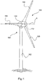
- FIG 1 shows a schematic representation of a wind turbine 100 according to the invention.
- the wind turbine 100 has a tower 102 and a nacelle 104 on the tower 102 .
- An aerodynamic rotor 106 with three rotor blades 108 and a spinner 110 is provided on the nacelle 104 .
- the rotor 106 is set in rotary motion by means of the wind and as a result turns a generator rotor or rotor of a generator (see FIG figure 2 ), which is directly or indirectly coupled to the rotor 106.
- the generator which is preferably a slowly rotating synchronous generator, is arranged in the nacelle 104 and generates electrical energy.
- the pitch angles of the rotor blades 108 are preferably changeable by means of pitch motors on the rotor blade roots in the rotor blades 108.
- the rotor 106 and the rotor blades 108 are rotatably mounted about an axis of rotation A by means of a main bearing 1, which is figure 2 is shown in more detail.
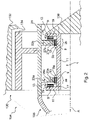
- the main bearing 1 shown has a first bearing section 3a and a second bearing section 3b which is spaced apart therefrom in the direction of the axis A.
- the main bearing 1 has a first radial bearing 5a and a first axial bearing 7a, which are each designed as plain bearings, preferably as hydrodynamic plain bearings.
- the main bearing has a second radial bearing 5b and a second axial bearing 7b, which are preferably also each designed as plain bearings, preferably as hydrodynamic plain bearings.
- the first and second radial bearing 5a, 5b each have sliding linings 9 which are fastened or formed on a first bearing ring 11.
- the sliding linings 9 are preferably partially or completely made of a fiber-reinforced composite material, for example glass fiber-reinforced plastic (GRP), and preferably have a number of friction-reducing surface layers 13 .
- the axial bearings 7a, 7b preferably also have sliding linings 9, which are partially or completely made of a fiber-reinforced composite material and have a number of surface layers 13 to reduce friction.
- the first axial bearing 7a is preferably arranged or formed on a first flange 15, which is reversibly detachably connected to the first bearing ring.
- a spacer 17 is particularly preferably arranged between the first flange 15 and the first bearing ring 11 in order to adjust the axial bearing clearance of the main bearing 1 .
- the second axial bearing is preferably arranged or formed on a second flange 19 .
- the second flange 19 is optionally formed on the first bearing ring 11 or the machine carrier 136 or attached thereto.
- the main bearing 1 has a second bearing ring 21, preferably designed as an outer ring.
- the second bearing ring 21 is non-rotatably connected to the rotor 106 on the one hand and non-rotatably to the rotor 134 of the generator 130 on the other.
- the second bearing ring 21 has in the first bearing section 3a a first radially inwardly extending collar 23a which interacts with the first radial bearing 5a and the first axial bearing 7a of the main bearing 1 .
- a radially aligned first surface section 25a is formed on the first collar 23a, which cooperates with the sliding lining 9 of the first radial bearing 5a to form a sliding bearing.
- a second surface section 25b is aligned on the first collar 23a, which is aligned axially and forms a sliding bearing with the sliding lining 9 of the first axial bearing 7a.
- the second bearing ring 21 has a second radially inwardly extending collar 23b, which is located in the second bearing section 3b.
- the second collar 23b has a first surface section 27a, which is aligned radially and forms a sliding bearing with the sliding lining 9 of the second radial bearing 5b.
- the second collar 23b has a second, axially aligned surface section 27b, which forms a sliding bearing with the sliding lining 9 of the second axial bearing 7b.
- the surface sections 25a,b and 27a,b are preferably formed from a metallic material and have a surface roughness R a of 1.0 ⁇ m or less, preferably 0.8 ⁇ m or less.
- metal inserts can be embedded in the collars 23a, b on the surface sections 25a, b, 27a, b, which inserts can be replaced after a predetermined wear limit has been reached.
- the slide linings 9 of the slide bearings 5a, b, 7a, b are preferably designed in the form of segmented slide bearing linings and are each reversibly detachably connected to the bodies 11, 15, 19 receiving them so that they can be changed when a predetermined wear limit is reached.
Landscapes
- Engineering & Computer Science (AREA)
- General Engineering & Computer Science (AREA)
- Mechanical Engineering (AREA)
- Life Sciences & Earth Sciences (AREA)
- Sustainable Energy (AREA)
- Sustainable Development (AREA)
- Chemical & Material Sciences (AREA)
- Combustion & Propulsion (AREA)
- Power Engineering (AREA)
- Wood Science & Technology (AREA)
- Sliding-Contact Bearings (AREA)
- Wind Motors (AREA)
Description
- Die vorliegende Erfindung betrifft eine Windenergieanlage, mit einem oder mehreren Rotorblättern, einer Rotornabe, an welcher das oder die Rotorblätter montiert sind, und einem Generator zur Erzeugung elektrischer Energie, wobei der Generator einen Generatorstator und einen mit der Rotornabe drehfest verbundenen, um eine Achse rotierbaren Generatorläufer aufweist, wobei die Rotornabe und der Generatorläufer drehfest verbunden sind.
- Windenergieanlagen der vorstehenden Art sind allgemein bekannt. Sie werden benutzt, um die Rotationsbewegung der Rotornabe, die infolge des Umstreichens der Rotorblätter mit Wind entsteht, in elektrische Energie zu wandeln.
- Hierbei kommt der Hauptlagerung der Rotornabe und des Generators eine wichtige Bedeutung zu. Die Hauptlagerung ist infolge der Rotationsbewegung und der Windlast axialen und auch radialen Belastungen ausgesetzt. Es haben sich im Laufe der Jahre vielfältige Lagerkonzepte in der Praxis etabliert oder auch nicht etabliert. Beispiele aus dem Stand der Technik werden in
US 2013/071246 ,EP 2 568 167 undUS 2014/169952 offenbart. In jüngerer Vergangenheit ist beispielsweise die Verwendung einer Hauptlagerung mit nur einem Lagerabschnitt zunehmend populär geworden, wobei in dem Lagerabschnitt ein oder mehrere Momentenlagerungen eingesetzt werden. Wenngleich der Vorteil einer Momentenlagerung als sehr tragfähige Lösung mit hoher Fähigkeit zur Aufnahme axialer Kräfte, radialer Kräfte und zur Aufnahme von Kippmomenten unbestritten ist, besteht dennoch ein Bedarf, alternative Lagerkonzepte zu ermitteln, die insbesondere einen guten Kompromiss aus Langlebigkeit, Wartungsaufwand, akustischem Dämpfungsverhalten und Kosteneffizienz erfordern. - Vor diesem Hintergrund lag der Erfindung die Aufgabe zugrunde, eine Windenergieanlage dahingehend zu verbessern, dass die vorstehend gennannten Vorteile in möglichst weitem Umfang erreicht werden. Insbesondere lag der Erfindung die Aufgabe zugrunde, eine Windenergieanlage anzugeben, bei der das Hauptlagerkonzept hinsichtlich der vorstehend genannten Eigenschaften verbessert wird.
- Die Erfindung löst die ihr zugrunde liegende Aufgabe bei einer Windenergieanlage der eingangs bezeichneten Art, indem die Windenergieanlage nach Anspruch 1 ausgebildet ist. Insbesondere weist bei der erfindungsgemäßen Windenergieanlage der erste Lagerabschnitt ein erstes Radialgleitlager und ein erstes Axialgleitlager auf, und der zweite Lagerabschnitt weist ein zweites Radialgleitlager und ein zweites Axialgleitlager auf. Die Erfindung macht sich die Erkenntnis zunutze, dass gegenüber Lagerungen mit nur einem Lagerabschnitt eine bessere Aufteilung der Kräfte erreicht wird. Insbesondere hat sich als Vorteil herausgestellt, dass die Aufteilung der axialen Kräfte auf die beiden Lagerabschnitte mit ihren jeweils dedizierten Axiallagern geringeren Lagerverschleiß mit sich bringt. Im Vergleich zu konventionellen Lagerungen wie beispielsweise Momentenlagern oder Fest-Los-Lagerungen besteht ein weiterer Vorteil darin, dass die Kippmomente, insbesondere in Form von Nick- und Giermomenten, die auf den Rotor wirken, besser isoliert in axiale und radiale Kraftanteile von den beiden Lagern abgestützt werden können. In der Regel ist die Zweilagerlösung weniger empfindlich gegenüber Giermomenten des Rotors im Vergleich zu dem Momentenlager.
- Die Erfindung wird vorteilhaft weitergebildet, indem das erste und zweite Radiallager jeweils einen Gleitbelag aufweisen, wobei die Gleitbeläge des ersten und zweiten Radialgleitlagers auf einem gemeinsamen ersten Lagerring angeordnet sind, welcher vorzugsweise ein Innenring ist. Die Radiallager sind vorzugsweise auf separaten Absätzen mit gleichen oder unterschiedlichen Durchmessern auf dem Innenring angeordnet.
- In einer weiteren bevorzugten Ausführungsform weist die Windenergieanlage eine Gondel mit einem fest installierten Maschinenträger auf, und der erste Lagerring ist fest mit dem Maschinenträger verbunden. Gegenüber einer konventionellen Ausgestaltung mit einem Achszapfen, auf dem jeweils in zwei Lagerabschnitten dezidierte Wälzlager oder Gleitlager mit eigenen Lagerringen montiert werden müssen, stellt diese Ausführungsform eine signifikante konstruktive Vereinfachung dar, indem der erste Lagerring die Gleitbeläge sowohl für den ersten Lagerabschnitt als auch für den zweiten Lagerabschnitt direkt trägt.
- Weiter vorzugsweise weisen das erste und zweite Axiallager jeweils ein Gleitlager auf, wobei vorzugsweise die Gleitbeläge einander zugewandt sind, und wobei der Gleitbelag des ersten Axialgleitlagers an einem Flansch des ersten Lagerrings angeordnet ist. Durch die Anordnung des Gleitbelags des ersten Axiallagers an einem Flansch wird mittels der Befestigung des Flansches am ersten Lagerring eine recht einfache Justierung des axialen Lagerspiels ermöglicht, indem beispielsweise zwischen dem Flansch und dem Ring Distanzscheiben verwendet werden.
- In einer ersten bevorzugten Alternative ist der Gleitbelag des zweiten Axialgleitlagers an dem Maschinenträger angeordnet. Alternativ dazu ist vorzugsweise der Flansch ein erster Flansch, und der erste Lagerring weist einen in Richtung der Achse gegenüberliegend angeordneten zweiten Flansch auf, wobei der Gleitbelag des zweiten Axialgleitlagers an dem zweiten Flansch angeordnet ist.
- Die Windenergieanlage gemäß der Erfindung weist vorzugsweise einen zweiten Lagerring auf, welcher vorzugsweise ein Außenring ist, und welcher drehfest mit dem Generatorläufer verbunden ist. In einer bevorzugten Ausgestaltung weist der zweite Lagerring in dem ersten Lagerabschnitt einen sich radial nach innen erstreckenden ersten Kragen auf, und in dem zweiten Lagerabschnitt einen sich radial nach innen erstreckenden zweiten Kragen, wobei der erste Kragen mit dem ersten Axiallager und dem ersten Radiallager zusammenwirkt, und wobei der zweite Kragen mit dem zweiten Axiallager und dem zweiten Radiallager zusammenwirkt. Der Kragen ist vorzugsweise zumindest abschnittsweise als umlaufende ringförmige Scheibe ausgebildet, die nach innen vom zweiten Lagerring vorsteht.
- In einer bevorzugten Ausgestaltung weist der erste Kragen einen radial ausgerichteten ersten Oberflächenabschnitt auf, der gleitend auf dem Gleitbelag des ersten Radiallagers läuft, und einen axial ausgerichteten zweiten Oberflächenabschnitt, der gleitend auf dem Gleitbelag des ersten Axiallagers läuft.
- Weiter vorzugsweise weist der zweite Kragen einen radial ausgerichteten ersten Oberflächenabschnitt auf, der gleitend auf dem Gleitbelag des zweiten Radiallagers läuft, und einen axial ausgerichteten zweiten Oberflächenabschnitt, der gleitend auf dem Gleitbelag des zweiten Axiallagers läuft.
- Weiter vorzugsweise bestehen der erste und/oder zweite Kragen, insbesondere die Oberflächenabschnitte des ersten und/oder zweiten Kragens, teilweise oder vollständig aus einem metallischen Werkstoff. Vorzugsweise ist die Rauheit der Oberflächenabschnitte an dem ersten und/oder zweiten Kragen mit einer Oberflächenrauheit Ra von 1,0 µm oder weniger, vorzugsweise 0,8 µm oder weniger ausgebildet. Die Oberflächenrauheit kann in allgemein bekannter Weise festgestellt werden, beispielsweise nach DIN EN ISO 4287:2010.
- Als metallischer Werkstoff wird vorzugsweise jeweils Messing, eine Messinglegierung, Weißmetall, etwa Blei, Zinn, Antimon, Wismut, Kupfer, eine Kupferlegierung, insbesondere eine Kupfer-Blei-Gusslegierung, eine Bronze-Gusslegierung, insbesondere Bleibronze, eine Bleibronze-Gusslegierung, eine Blei-Zinn-Gusslegierung, Aluminium, eine Aluminiumlegierung, insbesondere eine Aluminium-Zinn-Gusslegierung, eine Aluminium-Zink-Gusslegierung, Stahl, eine Stahllegierung, ein Sintermetall, oder eine Kombination aus mehreren davor genannten metallischen Werkstoffen verwendet.
- Alternativ zu einem rein metallischen Werkstoff wird vorzugsweise ein Metall-Verbundwerkstoff verwendet, etwa ein keramisch-metallischer Verbundwerkstoff (Cermet), oder ein Metall-Kunststoffverbundmaterial.
- Alternativ wird vorzugsweise für die Gleitflächen ein, insbesondere nichtmetallischer, Werkstoff wie beispielsweise Sinterkeramik (die als Bestandteil bspw. Metalloxide aufweisen können), ein Hochleistungskunststoff wie etwa ein thermoplastisches Hochleistungspolymer, insbesondere ein amorphes thermoplastisches Hochleistungspolymer, zum Beispiel Polyamidimid (PAI), gegebenenfalls mit Graphit- und/oder PTFE-Zusatz, verwendet.
- Die Radialgleitlager und/oder die axialen Gleitlager der erfindungsgemäßen Hauptlagerung sind vorzugsweise als hydrodynamische Gleitlager ausgebildet.
- Die Gleitbeläge sind vorzugsweise jeweils teilweise oder vollständig aus einem Faserverbundwerkstoff ausgebildet. Weiter vorzugsweise sind auf einer, mehreren oder sämtlichen Gleitflächen eine Anzahl von Gleitschichten aus jeweils einem der folgenden Materialien aufgetragen:
- Polytetrafluorethylen,
- expandiertes Polytetrafluorethylen,
- Molybdaendisulfid,
- Graphit,
- Graphen, oder einer Kombination aus mehreren dieser Materialien.
- Werden nichtmetallische Werkstoffe für die Gleitflächen verwendet, ist vorzugsweise eine Anzahl der gleitschichten aus einem aufgedampften metallischen Werkstoff ausgebildet.
- Weiter vorzugsweise weist der Faserverbundwerkstoff Fasermaterial auf, ausgewählt aus der Liste bestehend aus: Kohlenstofffasern, Glasfasern, Stahlfasern, Bambusfasern, oder einer Kombination aus mehreren dieser Materialien.
- Das Matrixmaterial des faserverstärkten Faserverbundwerkstoffs ist vorzugsweise ein Polymerwerkstoff, beispielsweise ein thermoplastisches oder duroplastisches Polymer, insbesondere duroplastisches Epoxidharz.
- Die Erfindung wird nachfolgend unter Bezugnahme auf die beigefügten Figuren anhand eines bevorzugten Ausführungsbeispiels näher erläutert. Hierbei zeigen:
- Figur 1
- eine schematische räumliche Ansicht einer Windenergieanlage gemäß der vorliegenden Erfindung, und
- Figur 2
- eine schematische Querschnittansicht zu der Gondel der Windenergieanlage gemäß
Figur 1 . -
Figur 1 zeigt eine schematische Darstellung einer Windenergieanlage 100 gemäß der Erfindung. Die Windenergieanlage 100 weist einen Turm 102 und eine Gondel 104 auf dem Turm 102 auf. An der Gondel 104 ist ein aerodynamischer Rotor 106 mit drei Rotorblättern 108 und einem Spinner 110 vorgesehen. Der Rotor 106 wird im Betrieb der Windenergieanlage 100 mittels des Windes in eine Drehbewegung versetzt und dreht hierdurch einen Generator-Rotor oder -Läufer eines Generators (sieheFigur 2 ), welcher direkt oder indirekt mit dem Rotor 106 gekoppelt ist. Der Generator, welcher vorzugsweise ein langsam drehender Synchrongenerator ist, ist in der Gondel 104 angeordnet und erzeugt elektrische Energie. Die Pitchwinkel der Rotorblätter 108 sind vorzugsweise mittels Pitchmotoren an den Rotorblattwurzeln bei den Rotorblättern 108 veränderbar. Der Rotor 106 und die Rotorblätter 108 sind um eine Rotationsachse A drehbar mittels einer Hauptlagerung 1 gelagert, die inFigur 2 näher dargestellt ist. - Die in
Fig. 2 gezeigte Hauptlagerung 1 weist einen ersten Lagerabschnitt 3a und einen dazu in Richtung der Achse A beabstandet angeordneten zweiten Lagerabschnitt 3b auf. Die Hauptlagerung 1 weist in dem ersten Lagerabschnitt 3a ein erstes Radiallager 5a und ein erstes Axiallager 7a auf, die jeweils als Gleitlager ausgebildet sind, vorzugsweise als hydrodynamische Gleitlager. In dem zweiten Lagerabschnitt 3b weist die Hauptlagerung ein zweites Radiallager 5b und ein zweites Axiallager 7b auf, die vorzugsweise ebenfalls jeweils als Gleitlager ausgebildet sind, vorzugsweise als hydrodynamische Gleitlager. - Das erste und zweite Radiallager 5a, 5b weisen jeweils Gleitbeläge 9 auf, die an einem ersten Lagerring 11 befestigt oder ausgebildet sind. Die Gleitbeläge 9 sind vorzugsweise teilweise der vollständig aus einem faserverstärkten Verbundwerkstoff, beispielsweise glasfaserverstärktem Kunststoff (GFK) ausgebildet und weisen vorzugsweise eine Anzahl von reibungsmindernden Oberflächenschichten 13 auf. Die Axiallager 7a, 7b weisen vorzugsweise ebenfalls Gleitbeläge 9 auf, die teilweise oder vollständig aus einem faserverstärkten Verbundwerkstoff ausgebildet sind und eine Anzahl von Oberflächenschichten 13 zur Reibminderung aufweisen.
- Das erste Axiallager 7a ist vorzugsweise an einem ersten Flansch 15 angeordnet bzw. ausgebildet, der reversibel lösbar mit dem ersten Lagerring verbunden ist. Besonders bevorzugt ist zur Einstellung des axialen Lagerspiels der Hauptlagerung 1 ein Distanzstück 17 zwischen dem ersten Flansch 15 und dem ersten Lagerring 11 angeordnet.
- Das zweite Axiallager ist vorzugsweise an einem zweiten Flansch 19 angeordnet bzw. ausgebildet. Der zweite Flansch 19 ist optional an dem ersten Lagerring 11 oder dem Maschinenträger 136 ausgebildet oder daran befestigt.
- Die Hauptlagerung 1 weist zusätzlich zu dem ersten Lagerring 11 einen zweiten Lagerring 21 auf, vorzugsweise ausgebildet als Außenring. Der zweite Lagerring 21 ist zum einen drehfest mit dem Rotor 106 verbunden, und zum anderen drehfest mit dem Läufer 134 des Generators 130.
- Der zweite Lagerring 21 weist in dem ersten Lagerabschnitt 3a einen ersten sich radial nach innen erstreckenden Kragen 23a auf, der mit dem ersten Radiallager 5a und dem ersten Axiallager 7a der Hauptlagerung 1 zusammenwirkt. An dem ersten Kragen 23a ist ein radial ausgerichteter erster Oberflächenabschnitt 25a ausgebildet, der mit dem Gleitbelag 9 des ersten Radiallagers 5a zum Ausbilden einer Gleitlagerung kooperiert. Ferner ist an dem ersten Kragen 23a ein zweiter Oberflächenabschnitt 25b ausgerichtet, der axial ausgerichtet ist und mit dem Gleitbelag 9 des ersten Axiallagers 7a eine Gleitlagerung ausbildet.
- Analog weist der zweite Lagerring 21 einen zweiten radial nach innen erstreckten Kragen 23b auf, der sich in zweiten Lagerabschnitt 3b befindet. Der zweite Kragen 23b weist einen ersten Oberflächenabschnitt 27a auf, der radial ausgerichtet ist und mit dem Gleitbelag 9 des zweiten Radiallagers 5b ein Gleitlager ausbildet. Ferner weist der zweite Kragen 23b einen zweiten, axial ausgerichteten Oberflächenabschnitt 27b auf, der mit dem Gleitbelag 9 des zweiten Axiallagers 7b ein Gleitlager ausbildet.
- Die Oberflächenabschnitte 25a,b und 27a,b sind vorzugsweise aus einem metallischen Werkstoff ausgebildet und weisen Oberflächenrauigkeit Ra von 1.0 µm oder weniger, vorzugsweise 0,8 µm oder weniger auf.
- In vorzugsweisen Ausgestaltungen können an den Oberflächenabschnitten 25a,b, 27a,b metallische Einsätze in die Kragen 23a,b eingelassen sein, die nach Erreichen eines vorbestimmten Grenzverschleißes gewechselt werden können.
- Die Gleitbeläge 9 der Gleitlager 5a,b, 7a,b sind vorzugsweise in Form von segmentierten Gleitlagerbelägen ausgebildet und jeweils reversibel lösbar mit den sie aufnehmenden Körpern 11, 15, 19 verbunden, um bei Erreichen eines vorbestimmten Grenzverschleißes gewechselt werden so können.
Claims (14)
- Windenergieanlage (100), miteinem oder mehreren Rotorblättern (108), einer Rotornabe (106), an welcher das oder die Rotorblätter montiert sind, undeinem Generator (130) zur Erzeugung elektrischer Energie, wobei der Generator einen Generatorstator (132) und einen mit der Rotornabe drehfest verbundenen, um eine Achse rotierbaren Generatorläufer (134) aufweist,wobei die Rotornabe und der Generatorläufer eine gemeinsame Hauptlagerung (1) aufweisen, welche in zwei voneinander in Richtung der Achse beabstandete Lagerabschnitte (3a, 3b) unterteilt ist,dadurch gekennzeichnet, dass der erste Lagerabschnitt (3a) ein erstes Radialgleitlager (5a) und ein erstes Axialgleitlager (7a) aufweist, und der zweite Lagerabschnitt (3b) ein zweites Radialgleitlager (5b) und ein zweites Axialgleitlager (7b) aufweist.
- Windenergieanlage nach Anspruch 1,
wobei das erste und zweite Radialgleitlager (5a, b) jeweils einen Gleitbelag (9) aufweisen, und wobei die Gleitbeläge des ersten und zweiten Radialgleitlagers auf einem gemeinsamen ersten Lagerring (11) angeordnet sind, welcher vorzugsweise ein Innenring ist. - Windenergieanlage nach Anspruch 2,
wobei wie Windenergieanlage eine Gondel (104) mit einem fest installierten Maschinenträger (136) aufweist, und der erste Lagerring (11) fest mit dem Maschinenträger verbunden ist. - Windenergieanlage nach einem der vorstehenden Ansprüche,wobei das erste und zweite Axialgleitlager (7a, b) jeweils einen Gleitbelag (9) aufweisen, wobei vorzugsweise die Gleitbeläge einander zugewandt sind, undwobei der Gleitbelag (9) des ersten Axialgleitlagers (7a) an einem Flansch (15) des ersten Lagerrings (11) angeordnet ist.
- Windenergieanlage nach Anspruch 4,
wobei der Gleitbelag (9) des zweiten Axialgleitlagers (7b) an dem Maschinenträger (136) angeordnet ist. - Windenergieanlage nach Anspruch 4,
wobei der Flansch (15) ein erster Flansch ist, und der erste Lagerring (11) einen in Richtung der Achse A gegenüberliegend angeordneten zweiten Flansch (19) aufweist, und wobei der Gleitbelag (9) des zweiten Axialgleitlagers (7) an dem zweiten Flansch (19) angeordnet ist. - Windenergieanlage nach einem der vorstehenden Ansprüche,
wobei die Hauptlagerung (1) einen zweiten Lagerring (21) aufweist, welcher vorzugsweise ein Außenring ist, und welcher drehfest mit dem Generatorläufer (132) verbunden ist. - Windenergieanlage nach Anspruch 7,wobei der zweite Lagerring (21) in dem ersten Lagerabschnitt (3a) einen sich radial nach innen erstreckenden ersten Kragen (23a) und in dem zweiten Lagerabschnitt (3b) einen sich radial nach innen erstreckenden zweiten Kragen (23b) aufweist,wobei der erste Kragen (23a) mit dem ersten Axialgleitlager (7a) und dem ersten Radialgleitlager (5a) zusammenwirkt, und der zweite Kragen (23b) mit dem zweiten Axialgleitlager (7b) und dem zweiten Radialgleitlager (5b) zusammenwirkt.
- Windenergieanlage nach Anspruch 8,
wobei der erste Kragen (23a) einen radial ausgerichteten ersten Oberflächenabschnitt (25a) aufweist, der gleitend auf dem Gleitbelag des ersten Radialgleitlagers (5b) läuft, und einen axial ausgerichteten zweiten Oberflächenabschnitt (27b) aufweist, der gleitend auf dem Gleitbelag des ersten Axialgleitlagers (7b) läuft. - Windenergieanlage nach Anspruch 8 oder 9,
wobei der zweite Kragen einen radial ausgerichteten ersten Oberflächenabschnitt (27a) aufweist, der gleitend auf dem Gleitbelag des zweiten Radialgleitlagers (5b) läuft, und einen axial ausgerichteten zweiten Oberflächenabschnitt (27b) aufweist, der gleitend auf dem Gleitbelag des zweiten Axialgleitlagers (7b) läuft. - Windenergieanlage nach einem der vorstehenden Ansprüche,
wobei die Radialgleitlager und/oder die Axialgleitlager als hydrodynamische Gleitlager ausgebildet sind. - Windenergieanlage nach einem der Ansprüche 2 bis 11,
wobei die Gleitbeläge (9) jeweils teilweise oder vollständig aus einem Faserverbundwerkstoff ausgebildet sind. - Windenergieanlage nach Anspruch 12,wobei auf einem, mehreren oder sämtlichen Gleitbelägen eine Anzahl von Gleitschichten aus jeweils einem der folgenden Materialien aufgetragen ist:- Polytetrafluorethylen,- expandiertes Polytetrafluorethylen,- Molybdaendisulfid,- Graphit,- Graphen,- aufgedampfter metallischer Werkstoff,oder einer Kombination aus mehreren dieser Materialien.
- Windenergieanlage nach einem der Ansprüche 12 oder 13, wobei der Faserverbundwerkstoff Fasermaterial aufweist, ausgewählt ist aus der Liste bestehend aus:- Kohlenstofffasern,- Glasfasern,- Stahlfasern,- Bambusfasern, odereiner Kombination aus mehreren dieser Materialien.
Applications Claiming Priority (2)
| Application Number | Priority Date | Filing Date | Title |
|---|---|---|---|
| DE102016209206.5A DE102016209206A1 (de) | 2016-05-27 | 2016-05-27 | Windenergieanlage |
| PCT/EP2017/058226 WO2017202533A1 (de) | 2016-05-27 | 2017-04-06 | Windenergieanlage |
Publications (2)
| Publication Number | Publication Date |
|---|---|
| EP3464896A1 EP3464896A1 (de) | 2019-04-10 |
| EP3464896B1 true EP3464896B1 (de) | 2022-09-21 |
Family
ID=58489673
Family Applications (1)
| Application Number | Title | Priority Date | Filing Date |
|---|---|---|---|
| EP17715919.1A Active EP3464896B1 (de) | 2016-05-27 | 2017-04-06 | Windenergieanlage |
Country Status (11)
| Country | Link |
|---|---|
| US (1) | US10669997B2 (de) |
| EP (1) | EP3464896B1 (de) |
| JP (1) | JP2019516908A (de) |
| KR (1) | KR20190014540A (de) |
| CN (1) | CN109312721B (de) |
| BR (1) | BR112018074290A2 (de) |
| CA (1) | CA3024888A1 (de) |
| DE (1) | DE102016209206A1 (de) |
| DK (1) | DK3464896T3 (de) |
| RU (1) | RU2710456C1 (de) |
| WO (1) | WO2017202533A1 (de) |
Cited By (1)
| Publication number | Priority date | Publication date | Assignee | Title |
|---|---|---|---|---|
| EP4495444A1 (de) | 2023-07-18 | 2025-01-22 | COB Bearings GmbH | Profiliertes gleitsegment |
Families Citing this family (12)
| Publication number | Priority date | Publication date | Assignee | Title |
|---|---|---|---|---|
| DE102018120808A1 (de) * | 2018-08-27 | 2020-02-27 | Renk Aktiengesellschaft | Lageranordnung und Einstellschraube zur Einstellung des Lagerspiels |
| DE102018120810A1 (de) * | 2018-08-27 | 2020-02-27 | Renk Aktiengesellschaft | Lageranordnung eines Rotors einer Windkraftanlage und Windkraftanlage |
| DE102018120806A1 (de) * | 2018-08-27 | 2020-02-27 | Renk Aktiengesellschaft | Lageranordnung eines Rotors einer Windkraftanlage |
| CN109929196A (zh) * | 2019-03-21 | 2019-06-25 | 江苏科麦特科技发展有限公司 | 一种航空航天电线电缆用耐磨损复合材料及制备方法 |
| AT522476B1 (de) * | 2019-05-21 | 2020-11-15 | Miba Gleitlager Austria Gmbh | Gondel für eine Windkraftanlage |
| EP3904710B1 (de) | 2020-04-28 | 2023-11-08 | Siemens Gamesa Renewable Energy A/S | Fluidfilmlager und windturbine |
| CN111692053A (zh) * | 2020-07-08 | 2020-09-22 | 湘电风能有限公司 | 一种风力发电机组主轴系传动系统 |
| EP4016809B1 (de) * | 2020-12-18 | 2023-01-04 | Wobben Properties GmbH | Segmentierter generator, generatorsegment und windenergieanlage sowie verfahren zur transportvorbereitung, zum transport und zur montage eines segmentierten generators sowie verfahren zur montage einer windenergieanlage |
| DE102024108257B4 (de) * | 2024-03-22 | 2025-12-04 | Schaeffler Technologies AG & Co. KG | Hauptlagerung einer Windkraftanlage |
| DE102024110596A1 (de) | 2024-04-16 | 2025-10-16 | Schaeffler Technologies AG & Co. KG | Segmentierte Gleitlagerung |
| DE102024113255A1 (de) * | 2024-05-13 | 2025-11-13 | Schaeffler Technologies AG & Co. KG | Lager- und Getriebeanordnung sowie Windkraftanlage |
| DE102024114054A1 (de) * | 2024-05-21 | 2025-11-27 | Schaeffler Technologies AG & Co. KG | Gleitlageranordnung zum Gleitlagern einer Rotorwelle einer Windenergieanlage |
Family Cites Families (42)
| Publication number | Priority date | Publication date | Assignee | Title |
|---|---|---|---|---|
| US4474529A (en) * | 1983-03-21 | 1984-10-02 | Kinsey Lewis R | Windmill |
| JPH0819284B2 (ja) | 1987-12-17 | 1996-02-28 | 三井石油化学工業株式会社 | ポリオレフィン製軸受 |
| NO320790B1 (no) | 2000-10-19 | 2006-01-30 | Scan Wind Group As | Vindkraftverk |
| DK174085B1 (da) * | 2001-04-02 | 2002-06-03 | Vestas Wind Sys As | Vindmølle med planetgear |
| RU19886U1 (ru) | 2001-05-24 | 2001-10-10 | Кулдышев Александр Константинович | Упорный подшипниковый узел скольжения |
| DE10255745A1 (de) | 2002-11-28 | 2004-06-17 | Jörck, Hartmut | Direkt angetriebene Windenergieanlage mit im Generator integriertem Lager |
| JP2006118552A (ja) | 2004-10-20 | 2006-05-11 | Mitsubishi Heavy Ind Ltd | 軸受装置 |
| JP2006312688A (ja) | 2005-05-09 | 2006-11-16 | Toyota Industries Corp | 摺動部材 |
| DE202007002609U1 (de) | 2007-02-19 | 2008-04-03 | Landwehr, Markus | Drehverbindung |
| DE102007041508A1 (de) * | 2007-08-31 | 2009-03-05 | Schaeffler Kg | Rotorlagerung für eine Windenergieanlage |
| DE102008023075B3 (de) * | 2008-05-09 | 2009-09-03 | Voith Patent Gmbh | Verfahren und Vorrichtung zum Bremsen einer Strömungsmaschine |
| CN102292562A (zh) | 2008-12-04 | 2011-12-21 | 约亨·科茨 | 复合钢轴承及制造方法 |
| DE102009053879A1 (de) * | 2009-11-20 | 2011-05-26 | Voith Patent Gmbh | Gezeitenkraftwerk und Verfahren für dessen Erstellung |
| IT1399201B1 (it) * | 2010-03-30 | 2013-04-11 | Wilic Sarl | Aerogeneratore e metodo di rimozione di un cuscinetto da un aerogeneratore |
| AT509625B1 (de) | 2010-04-14 | 2012-02-15 | Miba Gleitlager Gmbh | Lagerelement |
| AT509624B1 (de) | 2010-04-14 | 2012-04-15 | Miba Gleitlager Gmbh | Windkraftanlage |
| IT1399511B1 (it) * | 2010-04-22 | 2013-04-19 | Wilic Sarl | Generatore elettrico per un aerogeneratore e aerogeneratore equipaggiato con tale generatore elettrico |
| ITMI20110375A1 (it) * | 2011-03-10 | 2012-09-11 | Wilic Sarl | Turbina eolica |
| ITMI20110378A1 (it) * | 2011-03-10 | 2012-09-11 | Wilic Sarl | Macchina elettrica rotante per aerogeneratore |
| ITMI20110377A1 (it) * | 2011-03-10 | 2012-09-11 | Wilic Sarl | Macchina elettrica rotante per aerogeneratore |
| EP2511521B2 (de) | 2011-04-14 | 2021-06-16 | Siemens Gamesa Renewable Energy A/S | Blattlager |
| EP2568168A1 (de) | 2011-09-08 | 2013-03-13 | Siemens Aktiengesellschaft | Windturbine mit Driektantrieb |
| EP2568167A1 (de) * | 2011-09-08 | 2013-03-13 | Siemens Aktiengesellschaft | Windturbine mit Driektantrieb |
| MX345502B (es) * | 2011-12-21 | 2017-02-02 | Wobben Properties Gmbh | Góndola de instalación de energía eólica. |
| RU118701U1 (ru) | 2012-02-08 | 2012-07-27 | Открытое Акционерное Общество "Государственный Ракетный Центр Имени Академика В.П. Макеева" | Подшипниковая опора ротора ветроэнергетической установки |
| ITMI20120257A1 (it) * | 2012-02-21 | 2013-08-22 | Wilic Sarl | Macchina elettrica rotante per aerogeneratore |
| EP2657519B1 (de) * | 2012-04-26 | 2015-06-17 | Siemens Aktiengesellschaft | Windturbine |
| DE102012209592A1 (de) | 2012-06-06 | 2013-12-12 | Federal-Mogul Deva Gmbh | Gleitschicht und Gleitelement mit einer solchen Gleitschicht |
| JP5880707B2 (ja) * | 2012-06-19 | 2016-03-09 | 富士電機株式会社 | 複合すべり軸受およびこの軸受けを用いた風力発電装置 |
| WO2014012947A1 (en) * | 2012-07-16 | 2014-01-23 | Colipu A/S | A wind turbine gearbox |
| FR2996379B1 (fr) * | 2012-10-01 | 2014-10-17 | Ddis | Generateur electrique a multiples machines electriques |
| AT513507B1 (de) * | 2013-01-30 | 2014-05-15 | Miba Gleitlager Gmbh | Gleitlagerpaket |
| DE102013004339A1 (de) | 2013-03-14 | 2014-09-18 | Wilo Se | Pumpenaggregat mit einer einstückigen Lagereinheit |
| DK2796740T3 (en) * | 2013-04-26 | 2017-05-22 | Siemens Ag | Directly operated wind turbine with a slide bearing device |
| DK2837818T3 (en) * | 2013-08-13 | 2019-03-11 | Siemens Ag | Wind turbine with bend bearing lift device |
| US20150330367A1 (en) * | 2013-12-24 | 2015-11-19 | Google Inc. | Drive Mechanism Utilizing a Tubular Shaft and Fixed Central Shaft |
| EP2921728A1 (de) * | 2014-03-20 | 2015-09-23 | Areva Wind GmbH | Hybridwellenlager mit einem hydrodynamischen Lager und einem Wälzlager, Windgenerator mit einem Hybridwellenlager, Verwendung des Hybridwellenlagers und Verfahren zum Betrieb des Hybridwellenlagers |
| DE102014205637A1 (de) | 2014-03-26 | 2015-10-01 | Aktiebolaget Skf | Gleitlagersystem |
| DE102014220375A1 (de) | 2014-10-08 | 2016-04-28 | Aktiebolaget Skf | Lagerträger |
| DK3141747T3 (da) * | 2015-09-08 | 2020-11-09 | Siemens Gamesa Renewable Energy As | Forstærket leje af en vindmølle |
| DE102016208051A1 (de) * | 2016-05-10 | 2017-11-16 | Wobben Properties Gmbh | Windenergieanlagen-Rotorblatt, und Windenergieanlage mit selbigem |
| DE102016210039A1 (de) * | 2016-06-07 | 2017-12-07 | Wobben Properties Gmbh | Windenergieanlagen-Drehverbindung, Rotorblatt und Windenergieanlage mit selbiger |
-
2016
- 2016-05-27 DE DE102016209206.5A patent/DE102016209206A1/de not_active Withdrawn
-
2017
- 2017-04-06 JP JP2018562015A patent/JP2019516908A/ja active Pending
- 2017-04-06 BR BR112018074290-2A patent/BR112018074290A2/pt not_active Application Discontinuation
- 2017-04-06 CN CN201780032544.8A patent/CN109312721B/zh active Active
- 2017-04-06 US US16/304,581 patent/US10669997B2/en active Active
- 2017-04-06 DK DK17715919.1T patent/DK3464896T3/da active
- 2017-04-06 RU RU2018146493A patent/RU2710456C1/ru active
- 2017-04-06 CA CA3024888A patent/CA3024888A1/en not_active Abandoned
- 2017-04-06 EP EP17715919.1A patent/EP3464896B1/de active Active
- 2017-04-06 WO PCT/EP2017/058226 patent/WO2017202533A1/de not_active Ceased
- 2017-04-06 KR KR1020187037828A patent/KR20190014540A/ko not_active Ceased
Cited By (2)
| Publication number | Priority date | Publication date | Assignee | Title |
|---|---|---|---|---|
| EP4495444A1 (de) | 2023-07-18 | 2025-01-22 | COB Bearings GmbH | Profiliertes gleitsegment |
| DE102023118943A1 (de) | 2023-07-18 | 2025-01-23 | COB Bearings GmbH | Profiliertes Gleitsegment und dessen Anwendung |
Also Published As
| Publication number | Publication date |
|---|---|
| WO2017202533A1 (de) | 2017-11-30 |
| EP3464896A1 (de) | 2019-04-10 |
| CN109312721A (zh) | 2019-02-05 |
| DK3464896T3 (da) | 2022-10-10 |
| CA3024888A1 (en) | 2017-11-30 |
| DE102016209206A1 (de) | 2017-12-14 |
| KR20190014540A (ko) | 2019-02-12 |
| US20190195204A1 (en) | 2019-06-27 |
| CN109312721B (zh) | 2022-03-15 |
| RU2710456C1 (ru) | 2019-12-26 |
| US10669997B2 (en) | 2020-06-02 |
| BR112018074290A2 (pt) | 2019-03-12 |
| JP2019516908A (ja) | 2019-06-20 |
Similar Documents
| Publication | Publication Date | Title |
|---|---|---|
| WO2017202533A1 (de) | Windenergieanlage | |
| EP3464888B1 (de) | Windenergieanlagen-rotorblatt und windenergieanlage mit selbigem | |
| EP2816226B1 (de) | Windkraftanlage mit einem Gleitlager | |
| EP3455493B1 (de) | Windenergieanlagen-rotorblatt, und windenergieanlage mit selbigem | |
| EP3550140B1 (de) | Maschinenträger für eine windenergieanlage | |
| DE102014104863B4 (de) | Wälzlageranordnung und Windkraftanlage | |
| DE102012212792A1 (de) | Lageranordnung für eine Windkraftanlage | |
| DE102012012900A1 (de) | Planetengetriebe | |
| EP2419630A2 (de) | Windenergieanlage und antriebseinrichtung zur verstellung eines rotorblatts | |
| WO2015150159A1 (de) | Wälzlageranordnung und windkraftanlage | |
| WO2009094998A2 (de) | Wassergeschmierte lageranordnung | |
| DE102009017824A1 (de) | Übertragungsvorrichtung für eine Windturbine | |
| DE102010039778B4 (de) | Rotorblatt für Windenergieanlagen | |
| EP1354144B1 (de) | Hydrodynamisches axialgleitlager für einen generator | |
| WO2017178291A1 (de) | Generatorrotor für einen generator einer windenergieanlage oder eines wasserkraftwerks, sowie generator, windenergieanlage und wasserkraftwerk mit selbigem | |
| EP3645901B1 (de) | Windenergieanlagen-drehverbindung, und windenergieanlage mit selbiger | |
| DE102016118052B4 (de) | Wälzlager, Dichtelement und Windkraftanlage | |
| EP4012212B1 (de) | Lagergehäuse | |
| EP3301315A1 (de) | Gleitlager, drehmomentwandler und windkraftanlage | |
| EP2836707B1 (de) | Windenergieanlage mit aussenläufergenerator | |
| DE102019220197A1 (de) | Maschinenstrang für Windkraftanlagen, Windkraftanlage | |
| EP3441610B1 (de) | Vorrichtung für eine verbindung zwischen einem maschinenhaus und einer rotornabe einer windenergieanlage und windenergieanlage | |
| DE102024104797A1 (de) | Hydrodynamische Rotorwellengleitlagerung für eine Rotorwelle insbesondere einer Windkraftanlage | |
| WO2019201989A1 (de) | Generator einer windenergieanlage und windenergieanlage mit selbigem |
Legal Events
| Date | Code | Title | Description |
|---|---|---|---|
| STAA | Information on the status of an ep patent application or granted ep patent |
Free format text: STATUS: UNKNOWN |
|
| STAA | Information on the status of an ep patent application or granted ep patent |
Free format text: STATUS: THE INTERNATIONAL PUBLICATION HAS BEEN MADE |
|
| PUAI | Public reference made under article 153(3) epc to a published international application that has entered the european phase |
Free format text: ORIGINAL CODE: 0009012 |
|
| STAA | Information on the status of an ep patent application or granted ep patent |
Free format text: STATUS: REQUEST FOR EXAMINATION WAS MADE |
|
| 17P | Request for examination filed |
Effective date: 20190102 |
|
| AK | Designated contracting states |
Kind code of ref document: A1 Designated state(s): AL AT BE BG CH CY CZ DE DK EE ES FI FR GB GR HR HU IE IS IT LI LT LU LV MC MK MT NL NO PL PT RO RS SE SI SK SM TR |
|
| AX | Request for extension of the european patent |
Extension state: BA ME |
|
| DAV | Request for validation of the european patent (deleted) | ||
| DAX | Request for extension of the european patent (deleted) | ||
| REG | Reference to a national code |
Ref country code: DE Ref legal event code: R079 Ref document number: 502017013836 Country of ref document: DE Free format text: PREVIOUS MAIN CLASS: F03D0080700000 Ipc: F16C0033160000 |
|
| GRAP | Despatch of communication of intention to grant a patent |
Free format text: ORIGINAL CODE: EPIDOSNIGR1 |
|
| STAA | Information on the status of an ep patent application or granted ep patent |
Free format text: STATUS: GRANT OF PATENT IS INTENDED |
|
| RIC1 | Information provided on ipc code assigned before grant |
Ipc: F16C 33/18 20060101ALI20220307BHEP Ipc: F16C 17/26 20060101ALI20220307BHEP Ipc: F16C 25/02 20060101ALI20220307BHEP Ipc: F03D 9/25 20160101ALI20220307BHEP Ipc: F03D 15/20 20160101ALI20220307BHEP Ipc: F03D 80/70 20160101ALI20220307BHEP Ipc: F16C 33/16 20060101AFI20220307BHEP |
|
| INTG | Intention to grant announced |
Effective date: 20220405 |
|
| GRAS | Grant fee paid |
Free format text: ORIGINAL CODE: EPIDOSNIGR3 |
|
| GRAA | (expected) grant |
Free format text: ORIGINAL CODE: 0009210 |
|
| STAA | Information on the status of an ep patent application or granted ep patent |
Free format text: STATUS: THE PATENT HAS BEEN GRANTED |
|
| AK | Designated contracting states |
Kind code of ref document: B1 Designated state(s): AL AT BE BG CH CY CZ DE DK EE ES FI FR GB GR HR HU IE IS IT LI LT LU LV MC MK MT NL NO PL PT RO RS SE SI SK SM TR |
|
| REG | Reference to a national code |
Ref country code: GB Ref legal event code: FG4D Free format text: NOT ENGLISH |
|
| REG | Reference to a national code |
Ref country code: CH Ref legal event code: EP |
|
| REG | Reference to a national code |
Ref country code: DE Ref legal event code: R096 Ref document number: 502017013836 Country of ref document: DE |
|
| REG | Reference to a national code |
Ref country code: DK Ref legal event code: T3 Effective date: 20221006 |
|
| REG | Reference to a national code |
Ref country code: IE Ref legal event code: FG4D Free format text: LANGUAGE OF EP DOCUMENT: GERMAN |
|
| REG | Reference to a national code |
Ref country code: AT Ref legal event code: REF Ref document number: 1520083 Country of ref document: AT Kind code of ref document: T Effective date: 20221015 |
|
| REG | Reference to a national code |
Ref country code: NL Ref legal event code: FP |
|
| REG | Reference to a national code |
Ref country code: LT Ref legal event code: MG9D |
|
| PG25 | Lapsed in a contracting state [announced via postgrant information from national office to epo] |
Ref country code: SE Free format text: LAPSE BECAUSE OF FAILURE TO SUBMIT A TRANSLATION OF THE DESCRIPTION OR TO PAY THE FEE WITHIN THE PRESCRIBED TIME-LIMIT Effective date: 20220921 Ref country code: RS Free format text: LAPSE BECAUSE OF FAILURE TO SUBMIT A TRANSLATION OF THE DESCRIPTION OR TO PAY THE FEE WITHIN THE PRESCRIBED TIME-LIMIT Effective date: 20220921 Ref country code: NO Free format text: LAPSE BECAUSE OF FAILURE TO SUBMIT A TRANSLATION OF THE DESCRIPTION OR TO PAY THE FEE WITHIN THE PRESCRIBED TIME-LIMIT Effective date: 20221221 Ref country code: LV Free format text: LAPSE BECAUSE OF FAILURE TO SUBMIT A TRANSLATION OF THE DESCRIPTION OR TO PAY THE FEE WITHIN THE PRESCRIBED TIME-LIMIT Effective date: 20220921 Ref country code: LT Free format text: LAPSE BECAUSE OF FAILURE TO SUBMIT A TRANSLATION OF THE DESCRIPTION OR TO PAY THE FEE WITHIN THE PRESCRIBED TIME-LIMIT Effective date: 20220921 Ref country code: FI Free format text: LAPSE BECAUSE OF FAILURE TO SUBMIT A TRANSLATION OF THE DESCRIPTION OR TO PAY THE FEE WITHIN THE PRESCRIBED TIME-LIMIT Effective date: 20220921 |
|
| PG25 | Lapsed in a contracting state [announced via postgrant information from national office to epo] |
Ref country code: HR Free format text: LAPSE BECAUSE OF FAILURE TO SUBMIT A TRANSLATION OF THE DESCRIPTION OR TO PAY THE FEE WITHIN THE PRESCRIBED TIME-LIMIT Effective date: 20220921 Ref country code: GR Free format text: LAPSE BECAUSE OF FAILURE TO SUBMIT A TRANSLATION OF THE DESCRIPTION OR TO PAY THE FEE WITHIN THE PRESCRIBED TIME-LIMIT Effective date: 20221222 |
|
| PG25 | Lapsed in a contracting state [announced via postgrant information from national office to epo] |
Ref country code: SM Free format text: LAPSE BECAUSE OF FAILURE TO SUBMIT A TRANSLATION OF THE DESCRIPTION OR TO PAY THE FEE WITHIN THE PRESCRIBED TIME-LIMIT Effective date: 20220921 Ref country code: RO Free format text: LAPSE BECAUSE OF FAILURE TO SUBMIT A TRANSLATION OF THE DESCRIPTION OR TO PAY THE FEE WITHIN THE PRESCRIBED TIME-LIMIT Effective date: 20220921 Ref country code: PT Free format text: LAPSE BECAUSE OF FAILURE TO SUBMIT A TRANSLATION OF THE DESCRIPTION OR TO PAY THE FEE WITHIN THE PRESCRIBED TIME-LIMIT Effective date: 20230123 Ref country code: ES Free format text: LAPSE BECAUSE OF FAILURE TO SUBMIT A TRANSLATION OF THE DESCRIPTION OR TO PAY THE FEE WITHIN THE PRESCRIBED TIME-LIMIT Effective date: 20220921 Ref country code: CZ Free format text: LAPSE BECAUSE OF FAILURE TO SUBMIT A TRANSLATION OF THE DESCRIPTION OR TO PAY THE FEE WITHIN THE PRESCRIBED TIME-LIMIT Effective date: 20220921 |
|
| PG25 | Lapsed in a contracting state [announced via postgrant information from national office to epo] |
Ref country code: SK Free format text: LAPSE BECAUSE OF FAILURE TO SUBMIT A TRANSLATION OF THE DESCRIPTION OR TO PAY THE FEE WITHIN THE PRESCRIBED TIME-LIMIT Effective date: 20220921 Ref country code: PL Free format text: LAPSE BECAUSE OF FAILURE TO SUBMIT A TRANSLATION OF THE DESCRIPTION OR TO PAY THE FEE WITHIN THE PRESCRIBED TIME-LIMIT Effective date: 20220921 Ref country code: IS Free format text: LAPSE BECAUSE OF FAILURE TO SUBMIT A TRANSLATION OF THE DESCRIPTION OR TO PAY THE FEE WITHIN THE PRESCRIBED TIME-LIMIT Effective date: 20230121 Ref country code: EE Free format text: LAPSE BECAUSE OF FAILURE TO SUBMIT A TRANSLATION OF THE DESCRIPTION OR TO PAY THE FEE WITHIN THE PRESCRIBED TIME-LIMIT Effective date: 20220921 |
|
| REG | Reference to a national code |
Ref country code: DE Ref legal event code: R097 Ref document number: 502017013836 Country of ref document: DE |
|
| PG25 | Lapsed in a contracting state [announced via postgrant information from national office to epo] |
Ref country code: AL Free format text: LAPSE BECAUSE OF FAILURE TO SUBMIT A TRANSLATION OF THE DESCRIPTION OR TO PAY THE FEE WITHIN THE PRESCRIBED TIME-LIMIT Effective date: 20220921 |
|
| PLBE | No opposition filed within time limit |
Free format text: ORIGINAL CODE: 0009261 |
|
| STAA | Information on the status of an ep patent application or granted ep patent |
Free format text: STATUS: NO OPPOSITION FILED WITHIN TIME LIMIT |
|
| 26N | No opposition filed |
Effective date: 20230622 |
|
| PG25 | Lapsed in a contracting state [announced via postgrant information from national office to epo] |
Ref country code: SI Free format text: LAPSE BECAUSE OF FAILURE TO SUBMIT A TRANSLATION OF THE DESCRIPTION OR TO PAY THE FEE WITHIN THE PRESCRIBED TIME-LIMIT Effective date: 20220921 |
|
| REG | Reference to a national code |
Ref country code: CH Ref legal event code: PL |
|
| PG25 | Lapsed in a contracting state [announced via postgrant information from national office to epo] |
Ref country code: LU Free format text: LAPSE BECAUSE OF NON-PAYMENT OF DUE FEES Effective date: 20230406 |
|
| REG | Reference to a national code |
Ref country code: BE Ref legal event code: MM Effective date: 20230430 |
|
| PG25 | Lapsed in a contracting state [announced via postgrant information from national office to epo] |
Ref country code: MC Free format text: LAPSE BECAUSE OF FAILURE TO SUBMIT A TRANSLATION OF THE DESCRIPTION OR TO PAY THE FEE WITHIN THE PRESCRIBED TIME-LIMIT Effective date: 20220921 |
|
| PG25 | Lapsed in a contracting state [announced via postgrant information from national office to epo] |
Ref country code: MC Free format text: LAPSE BECAUSE OF FAILURE TO SUBMIT A TRANSLATION OF THE DESCRIPTION OR TO PAY THE FEE WITHIN THE PRESCRIBED TIME-LIMIT Effective date: 20220921 Ref country code: LI Free format text: LAPSE BECAUSE OF NON-PAYMENT OF DUE FEES Effective date: 20230430 Ref country code: CH Free format text: LAPSE BECAUSE OF NON-PAYMENT OF DUE FEES Effective date: 20230430 |
|
| REG | Reference to a national code |
Ref country code: IE Ref legal event code: MM4A |
|
| PG25 | Lapsed in a contracting state [announced via postgrant information from national office to epo] |
Ref country code: BE Free format text: LAPSE BECAUSE OF NON-PAYMENT OF DUE FEES Effective date: 20230430 |
|
| PG25 | Lapsed in a contracting state [announced via postgrant information from national office to epo] |
Ref country code: IE Free format text: LAPSE BECAUSE OF NON-PAYMENT OF DUE FEES Effective date: 20230406 |
|
| PG25 | Lapsed in a contracting state [announced via postgrant information from national office to epo] |
Ref country code: IE Free format text: LAPSE BECAUSE OF NON-PAYMENT OF DUE FEES Effective date: 20230406 |
|
| PG25 | Lapsed in a contracting state [announced via postgrant information from national office to epo] |
Ref country code: IT Free format text: LAPSE BECAUSE OF FAILURE TO SUBMIT A TRANSLATION OF THE DESCRIPTION OR TO PAY THE FEE WITHIN THE PRESCRIBED TIME-LIMIT Effective date: 20220921 |
|
| REG | Reference to a national code |
Ref country code: AT Ref legal event code: MM01 Ref document number: 1520083 Country of ref document: AT Kind code of ref document: T Effective date: 20230406 |
|
| PG25 | Lapsed in a contracting state [announced via postgrant information from national office to epo] |
Ref country code: AT Free format text: LAPSE BECAUSE OF NON-PAYMENT OF DUE FEES Effective date: 20230406 |
|
| PG25 | Lapsed in a contracting state [announced via postgrant information from national office to epo] |
Ref country code: AT Free format text: LAPSE BECAUSE OF NON-PAYMENT OF DUE FEES Effective date: 20230406 |
|
| PG25 | Lapsed in a contracting state [announced via postgrant information from national office to epo] |
Ref country code: BG Free format text: LAPSE BECAUSE OF FAILURE TO SUBMIT A TRANSLATION OF THE DESCRIPTION OR TO PAY THE FEE WITHIN THE PRESCRIBED TIME-LIMIT Effective date: 20220921 |
|
| PG25 | Lapsed in a contracting state [announced via postgrant information from national office to epo] |
Ref country code: BG Free format text: LAPSE BECAUSE OF FAILURE TO SUBMIT A TRANSLATION OF THE DESCRIPTION OR TO PAY THE FEE WITHIN THE PRESCRIBED TIME-LIMIT Effective date: 20220921 |
|
| PG25 | Lapsed in a contracting state [announced via postgrant information from national office to epo] |
Ref country code: CY Free format text: LAPSE BECAUSE OF FAILURE TO SUBMIT A TRANSLATION OF THE DESCRIPTION OR TO PAY THE FEE WITHIN THE PRESCRIBED TIME-LIMIT; INVALID AB INITIO Effective date: 20170406 |
|
| PG25 | Lapsed in a contracting state [announced via postgrant information from national office to epo] |
Ref country code: HU Free format text: LAPSE BECAUSE OF FAILURE TO SUBMIT A TRANSLATION OF THE DESCRIPTION OR TO PAY THE FEE WITHIN THE PRESCRIBED TIME-LIMIT; INVALID AB INITIO Effective date: 20170406 |
|
| PGFP | Annual fee paid to national office [announced via postgrant information from national office to epo] |
Ref country code: GB Payment date: 20260324 Year of fee payment: 10 |
|
| PGFP | Annual fee paid to national office [announced via postgrant information from national office to epo] |
Ref country code: NL Payment date: 20260422 Year of fee payment: 10 |
|
| PGFP | Annual fee paid to national office [announced via postgrant information from national office to epo] |
Ref country code: DK Payment date: 20260422 Year of fee payment: 10 |
|
| PGFP | Annual fee paid to national office [announced via postgrant information from national office to epo] |
Ref country code: DE Payment date: 20260504 Year of fee payment: 10 |
|
| PGFP | Annual fee paid to national office [announced via postgrant information from national office to epo] |
Ref country code: TR Payment date: 20260402 Year of fee payment: 10 |
|
| PGFP | Annual fee paid to national office [announced via postgrant information from national office to epo] |
Ref country code: FR Payment date: 20260423 Year of fee payment: 10 |