EP3465301B1 - Dispositif à fibre optique - Google Patents
Dispositif à fibre optique Download PDFInfo
- Publication number
- EP3465301B1 EP3465301B1 EP17727664.9A EP17727664A EP3465301B1 EP 3465301 B1 EP3465301 B1 EP 3465301B1 EP 17727664 A EP17727664 A EP 17727664A EP 3465301 B1 EP3465301 B1 EP 3465301B1
- Authority
- EP
- European Patent Office
- Prior art keywords
- optical fibre
- dopant
- refractive index
- core
- optical
- Prior art date
- Legal status (The legal status is an assumption and is not a legal conclusion. Google has not performed a legal analysis and makes no representation as to the accuracy of the status listed.)
- Active
Links
Images











Classifications
-
- G—PHYSICS
- G02—OPTICS
- G02B—OPTICAL ELEMENTS, SYSTEMS OR APPARATUS
- G02B6/00—Light guides; Structural details of arrangements comprising light guides and other optical elements, e.g. couplings
- G02B6/24—Coupling light guides
- G02B6/255—Splicing of light guides, e.g. by fusion or bonding
- G02B6/2551—Splicing of light guides, e.g. by fusion or bonding using thermal methods, e.g. fusion welding by arc discharge, laser beam, plasma torch
-
- G—PHYSICS
- G02—OPTICS
- G02B—OPTICAL ELEMENTS, SYSTEMS OR APPARATUS
- G02B6/00—Light guides; Structural details of arrangements comprising light guides and other optical elements, e.g. couplings
- G02B6/02—Optical fibres with cladding with or without a coating
- G02B6/02057—Optical fibres with cladding with or without a coating comprising gratings
- G02B6/02076—Refractive index modulation gratings, e.g. Bragg gratings
- G02B6/0208—Refractive index modulation gratings, e.g. Bragg gratings characterised by their structure, wavelength response
- G02B6/021—Refractive index modulation gratings, e.g. Bragg gratings characterised by their structure, wavelength response characterised by the core or cladding or coating, e.g. materials, radial refractive index profiles, cladding shape
-
- G—PHYSICS
- G02—OPTICS
- G02B—OPTICAL ELEMENTS, SYSTEMS OR APPARATUS
- G02B6/00—Light guides; Structural details of arrangements comprising light guides and other optical elements, e.g. couplings
- G02B6/02—Optical fibres with cladding with or without a coating
- G02B6/036—Optical fibres with cladding with or without a coating core or cladding comprising multiple layers
- G02B6/03605—Highest refractive index not on central axis
- G02B6/03611—Highest index adjacent to central axis region, e.g. annular core, coaxial ring, centreline depression affecting waveguiding
-
- G—PHYSICS
- G02—OPTICS
- G02B—OPTICAL ELEMENTS, SYSTEMS OR APPARATUS
- G02B6/00—Light guides; Structural details of arrangements comprising light guides and other optical elements, e.g. couplings
- G02B6/02—Optical fibres with cladding with or without a coating
- G02B6/036—Optical fibres with cladding with or without a coating core or cladding comprising multiple layers
- G02B6/03616—Optical fibres characterised both by the number of different refractive index layers around the central core segment, i.e. around the innermost high index core layer, and their relative refractive index difference
- G02B6/03622—Optical fibres characterised both by the number of different refractive index layers around the central core segment, i.e. around the innermost high index core layer, and their relative refractive index difference having 2 layers only
-
- G—PHYSICS
- G02—OPTICS
- G02B—OPTICAL ELEMENTS, SYSTEMS OR APPARATUS
- G02B6/00—Light guides; Structural details of arrangements comprising light guides and other optical elements, e.g. couplings
- G02B6/02—Optical fibres with cladding with or without a coating
- G02B6/036—Optical fibres with cladding with or without a coating core or cladding comprising multiple layers
- G02B6/03694—Multiple layers differing in properties other than the refractive index, e.g. attenuation, diffusion, stress properties
-
- G—PHYSICS
- G02—OPTICS
- G02B—OPTICAL ELEMENTS, SYSTEMS OR APPARATUS
- G02B6/00—Light guides; Structural details of arrangements comprising light guides and other optical elements, e.g. couplings
- G02B6/24—Coupling light guides
- G02B6/255—Splicing of light guides, e.g. by fusion or bonding
- G02B6/2552—Splicing of light guides, e.g. by fusion or bonding reshaping or reforming of light guides for coupling using thermal heating, e.g. tapering, forming of a lens on light guide ends
Definitions
- This invention relates to an optical fibre device comprising an optical fibre.
- the optical fibre has a first refractive index profile that can be changed by heating to a second refractive index profile, and so change an optical guidance property of the optical fibre such that the optical fibre can be used in different optical devices having different requirements.
- the invention may be used to simplify splicing between dissimilar optical fibres that are used in high power laser applications. More specifically, the invention enables splicing of the optical fibre to a second optical fibre having a different mode field diameter or a different optical power distribution without tapering the outside cladding.
- the second optical fibre may be, for example, part of an optical amplifier, a laser, or a master oscillator power amplifier.
- High power lasers have important applications in the laser processing of industrial materials. Pulsed lasers, with peak powers exceeding 10kW, are used in marking, engraving, cutting, welding, and drilling applications. Continuous wave lasers with powers exceeding 500W are used in cutting and welding applications. These high power lasers typically comprise more than one specialist optical fibre that have dissimilar optical properties. It is often difficult to make low optical loss splices between such fibres reliably.
- High power industrial fibre lasers use amplifying optical fibres as the gain medium. For many applications, good beam quality is desired, and thus the amplifying optical fibres need to output single-mode or low-moded laser radiation.
- the amplifying fibre In order to achieve high power (>1kW) and high peak powers (>10kW), the amplifying fibre needs to be a large mode area fibre to reduce non-linear effects. This is especially the case in picosecond (ps) lasers which can have peak powers exceeding 100kW.
- Such large mode area fibres are multimoded and are configured in the laser to output single mode radiation.
- Such fibres can have larger mode field diameters than fibres that connect with them, and thus tapering between the different fibre types is often required in order to achieve low loss splices.
- certain amplifying fibres can experience photodarkening whereby the attenuation of the amplifying fibre increases over time. Elimination of photodarkening places constraints on dopant selection and dopant concentration within the amplifying fibre.
- High power industrial lasers advantageously have optical fibre beam delivery systems for delivering the laser radiation from the laser to a work piece.
- non-linear effects such as Raman scattering and stimulating Raman scattering can limit the maximum output power and the length of the optical fibre beam delivery system, as well as impacting the ability of the laser to withstand back reflection from the work piece.
- the maximum length for some systems can be as small as 1m to 2m. This places serious limitations on the design of laser processing machines such as flat bed cutters, or the design of manufacturing shop floors, as well as on the architecture of the laser source itself.
- Non-linear effects are reduced with increasing core diameter, and thus optical fibres used in optical fibre beam delivery systems typically have larger core diameters than other signal fibres within the laser.
- Prior art splices between dissimilar fibres either use dopant diffusion within the splice, by inserting an intermediate fibre between the two fibres being spliced, or by inserting or creating a physical taper of the outside of the fibre.
- the dopant diffusion is generally preferred as it can be carried out in the fusion splicer used for splicing the two fibres together. Tapering the outside of the fibre is used if the mode mismatch between the fibres is too great, or if the dopants do not diffuse reliably enough.
- the degree of freedom of the dopant diffusion process is limited by the diffusion properties of the dopants.
- additional tapering of the outside of at least one of the fibres is required to obtain a low loss splice.
- additional tapering cannot reduce losses to acceptable amounts if there is a large mismatch in numerical apertures between the fibres.
- Prior art dopant diffusion processes are often referred to as thermally expanded cores because diffusion is caused by heating, and the core dopants diffuse into the cladding, thus expanding the size of the core, and thus increasing the mode field area of the guided modes. Thermally expanded cores are used in splices between two optical fibres both having Gaussian shaped modes.
- United States Patent Application No. US 2003/012526 describes techniques and systems for reducing splice loss in an optical fiber transmission line.
- One described technique includes splicing together at a splice point a first fiber having a first modefield diameter to a second fiber having a second modefield diameter larger than the first modefield diameter.
- the splice point is heated to a core expansion temperature to cause a controlled thermal diffusion of core dopant in the first fiber in order to reduce modefield mismatch between the first and second fibers.
- Splice loss is then reduced by heating the splice point to a differential diffusion temperature to cause a controlled diffusion of a cladding dopant in the first fiber, while maintaining the expanded core.
- European Patent No. 1202090 describes an optical splice between a dispersion compensating fibre and a transmission fibre.
- the dispersion compensating fibre is a so-called "W-fibre" having a narrow fluorine doped ring around the core.
- the transmission fibre is a low-loss depressed cladding telecommunications fibre having multiple fluorophosphorus doped layers around the core. Splicing of the two fibres causes problems owing to the different diffusion rates of germania in the core and fluorine in the claddings between the two fibres.
- the solution is to use a bridge or intermediate fibre between the two fibres in order to form a low loss splice.
- European Patent No. 1343032 describes a dispersion compensating optical fibre designed to reduce splice losses when splicing the dispersion compensating fiber either to itself or to other kinds of fibres, such as a single-mode standard fibre using a bridge or intermediate fibre.
- the dispersion compensating fibre has a core and a cladding.
- the cladding has a first cladding region surrounding the core, a second cladding region surrounding the first cladding layer, and a third cladding region surrounding the second cladding layer.
- the core, and the first, second, and third cladding regions are doped to create a refraction index profile characteristic of a dispersion compensating fibre.
- a portion of the cladding is doped with phosphorus, thereby resulting in splice loss reduction.
- United States Patent No. 6,336,749 describes a splice between a first fibre and a second fibre in which diffusion of the dopants in the second fibre causes its refractive index profile to converge optically to that of the first fibre.
- the optical losses associated with the splice are relatively low, i.e. less than 0.2 dB at the operating wavelength, even when there is relatively high mismatch between the mode field diameters and mode field shapes (at a signal wavelength) in the respective fibres.
- United States Patent No. 5,381,503 discloses an optical waveguide comprising a core portion made of a light propagating material and a cladding portion, a first dopant and a second dopant being induced into said core portion, the first dopant having a function of increasing a refractive index of the light propagating material and having a first thermal diffusion coefficient to said light propagating material, the second dopant having a function of decreasing the refractive index of said light propagating material and having a second thermal diffusion coefficient to the light propagating material larger than the first thermal diffusion coefficient under a predetermined temperature.
- the patent teaches how to splice two single mode fibres together that have different mode field diameters.
- the patent does not teach how to design a mode field adaptor that can change the shape of the mode.
- United States Patent No. 6,742,939 discloses a fusion splice including a first optical fibre having a first mode field diameter and a first mode field diameter expansion rate.
- the splice further includes a second fibre having a second mode field diameter and a second mode field diameter expansion rate, wherein the second mode field diameter is lower than the first mode field diameter.
- the second fibre comprises a core, a cladding radially surrounding the core, and a zone of high concentration of fluorine between the core and the cladding.
- the rate of mode field diameter expansion of the first fibre is less than the rate of mode field expansion of the second fibre during the fusion splicing operation.
- a further limitation of dopant diffusion and tapering processes is that fibres with dissimilar mode shapes are difficult to splice together.
- the prior art solutions enable single mode fibres to be spliced to single mode fibres that have different mode field diameters with low loss. However, they are not suited for splicing fibres that have substantially different mode field diameters, or fibres whose refractive index profiles have substantially different shapes. For example, splicing from a Gaussian mode from a step index fibre to a doughnut mode from a ring core fibre would be difficult if not impossible with prior art techniques.
- an optical fibre device in accordance with claim 1.
- the concealed dopant is incorporated into the optical fibre at concentrations much higher than required to provide the desired first refractive index profile.
- the concealed dopant may be disposed in a different region of the optical fibre than the first dopant.
- a mobile dopant for example fluorine
- the mobile dopant is added to mask the presence of the concealed dopant. It is the combination of the effects of the concealed dopant and the diffusion of the mobile dopant that enables far greater control of changes in refractive index and hence mode transformation compared to the prior art.
- the mode transformation can be changes in either or both mode shape and mode field diameter. This can be beneficial for the manufacturing of various optical devices as will be described below.
- An optical fibre having the first refractive index profile will guide a mode with a first optical power distribution. After the first refractive index profile has been changed to the second refractive index profile by heating, the mode will have a second optical power distribution that is different from the first optical power distribution.
- the ability to control the optical power distribution along the optical fibre by controlled heating enables the fabrication of optical devices such as optical mode transformers, optical mode converters, optical mode scramblers, optical wavelength filters, long period gratings, optical signal combiners and couplers, multi-core optical fibre couplers, and output beam delivery cables.
- the first optical power distribution may be the optical power distribution of the fundamental mode of the optical fibre.
- the first optical power distribution may be characterized by a mode field diameter and a mode shape.
- changes in the mode field diameter greater than 100% are obtainable without requiring tapering of the outside diameter of the optical fibre.
- Changes to the mode shape are also readily obtainable, including from a Gaussian to a top hat mode or doughnut mode.
- such changes can be tailored by suitable design of the heat profile along the heat affected region, allowing a single fibre to be used for a number of different modal transformations. This delivers substantial cost reduction and flexibility in components and laser design.
- the first and second optical power distributions can be calculated from the first and the second refractive index profiles using Maxwell's equations, or in the limit of small refractive index variations, the Helmholtz equation.
- the first and the second refractive index profiles can therefore be obtained from an inverse transform of the first and second optical power distributions.
- controlled heating of the optical fibre enables the first optical power distribution to be changed adiabatically along the optical fibre to a second optical power distribution that is more suited for splicing to a second optical fibre.
- the optical fibre can be spliced to the second optical fibre using a splicing process that is much quicker than obtained using prior art techniques, requiring less heat energy, and consequently less sagging. For example, in splicing from a 10 ⁇ m core diameter fibre to a 25 ⁇ m core diameter active fibre, splicing times may be able to be reduced from approximately 60 seconds using prior art thermally expanded core techniques to approximately 11 to 14 seconds using an optical fibre according to the present invention.
- the mobile dopant has a diffusion constant that is greater than the diffusion constant of the concealed dopant. Therefore, when the optical fibre is heated, the mobile dopant diffuses faster than the concealed dopant resulting in the change from the first refractive index profile to the second refractive index profile. Incorporation of the mobile and concealed dopants enables large changes to the first refractive index profile of the optical fibre to be obtained by heating. Heating thus reveals the presence of the mobile and concealed dopants in the optical fibre.
- the concealed dopant may be in a different region of the optical fibre than the first dopant.
- the cross-sectional area of the region comprising the concealed dopant may be at least two times the cross sectional area of the region comprising the first dopant.
- the cross-sectional area of the region comprising the concealed dopant may be at least five times the cross sectional area of the region comprising the first dopant.
- the cross-sectional area of the region comprising the concealed dopant may be at least ten times the cross sectional area of the region comprising the first dopant.
- Incorporating the concealed dopant at such high concentrations and over such large areas enables much greater design flexibility in obtaining the desired change in the optical guidance property of the optical fibre.
- This efficiency can be quantified by a figure of merit defined as the root mean square of the change in the first refractive index profile caused by heating, divided by the maximum concentration of the mobile dopant, multiplied by the ratio of the maximum to the minimum of the mode field diameter before heating and the mode field diameter after heating, averaged over a cross-sectional area having a diameter that is twice the maximum of the mode field diameter before heating and the mode field diameter after heating.
- the figure of merit may be at least 50.
- the figure of merit may be at least 100.
- the figure of merit may be at least 200.
- the optical fibre may have a fundamental mode defined by an M 2 value prior to heating that is less than 1.15, and has a fundamental mode defined by an M 2 value after heating that is at least 1.2.
- the M 2 value after heating may be at least 1.3.
- the M 2 value after heating may be at least 1.5.
- the M 2 value is a measure of the beam quality, an M 2 value of 1.0 corresponding to a Guassian beam.
- the M 2 value is a measure of the shape of the fundamental mode, the higher the M 2 value, the less Gaussian the mode. In order to achieve low splice losses of the fundamental modes guided by two optical fibres, it is necessary to match the size and shape of the fundamental modes. The ability to provide such large changes in the M 2 value by heating is an advantage of the present invention.
- the optical fibre may be a single mode optical fibre prior to heating, and a multi mode optical fibre after heating.
- the optical fibre may be a multimode optical fibre prior to heating, and more multimoded after heating.
- the disposition and concentration of the concealed and mobile dopants may be such that heating of the optical fibre results in the fundamental mode having a top hat optical power distribution.
- the disposition and concentration of the concealed and mobile dopants may be such that heating of the optical fibre results in the fundamental mode having a doughnut optical power distribution.
- the doped region may surround the core, and the magnitude of a product of the concentration of the concealed dopant and the molar refractivity of the concealed dopant may be greater than the difference between the refractive index of the core and a refractive index of doped region surrounding the core prior to heating.
- the doped region may surround the core, and the magnitude of a refractive index change induced by incorporating the mobile dopant into the optical fibre may be greater than the difference between the refractive index of the core and a refractive index of the doped region prior to heating.
- the refractive index of the core can be made to change more quickly if the concentration of the first dopant is less than the concentration of the concealed dopant than if the concentration of the first dopant is more than the concentration of the concealed dopant.
- This enables splices to be made more quickly than if the concentration of the first dopant were equal to or greater than the concentration of the concealed dopant, leading to more reliable splices.
- it also allows much larger and more flexible modal transformations, including changes in the shape of the fundamental and other guided modes, than obtainable by prior art methods.
- the core may support a fundamental mode having a mode field diameter prior to heating.
- the mode field diameter after heating may be greater than the mode field diameter prior to heating.
- the mode field diameter after heating may be at least 1.5 times greater than the mode field diameter prior to heating.
- the mode field diameter after heating may be at least 2.0 times greater than the mode field diameter prior to heating.
- the concealed and mobile dopants may have a disposition and a concentration such that the diffusion of the mobile dopant increases an effective mode area of a fundamental mode guided by the optical fibre.
- Designing the optical fibre such that heating causes at least one of the mode field diameter and the effective mode area to increase enables the optical fibre to be spliced to a fibre that is more multimoded than the optical fibre.
- the doped region may surround the core.
- the concentration and position of the concealed dopant and the mobile dopant may be such that heating of the optical fibre causes a reduction in the refractive index of the core. Further heating of the optical fibre may cause the refractive index of the core to become equal to a refractive index of the doped region. Designing the optical fibre such that if heated the refractive index of the core becomes equal to the refractive index of the doped region, enables splices to be made to fibres having a core diameter that is larger than the core diameter of the optical fibre prior to heating. If the optical fibre has a substantially step index core, then the optical fibre after reheating will also have a substantially step index core, but one with a smaller refractive index, and larger core diameter. This enables fibres with different core sizes to be spliced together without necessitating tapering the outside of one or both of the fibres, or using tapers that are spliced between the two fibres.
- the concealed dopant and the mobile dopant may have a concentration and position such that the diffusion of the mobile dopant causes an increase in the refractive index of the core.
- the concealed dopant and the mobile dopant may have a position and a concentration such that the diffusion of the mobile dopant decreases a mode field diameter of a fundamental mode guided by the optical fibre.
- the modal behaviour of an optical fibre is defined at its operating wavelength.
- the operating wavelength may be in a visible or near infrared wavelength range.
- the wavelength range may be 1000nm to 1100nm, 1300nm to 1350nm, 1500nm to 1600nm, or 1900nm to 2500nm.
- Ytterbium doped fibre lasers operate in the wavelength range 1000nm to 1100nm.
- a step index optical fibre that has a normalized frequency less than 2.405 is a single mode fibre.
- a step index fibre with a normalized frequency of at least 2.405, and preferably greater than 4 is a multimode fibre.
- Coupling from a singlemode fibre laser into a multimode fibre with low loss and high modal purity allows single mode propagation through the multimode fibre, thereby avoiding the effects of stimulated Raman scattering and other non-linear optical effects. This is especially important for power levels greater than 1kW, 2kW, or 10kW, and more important for pulsed lasers having peak powers greater than 10kW.
- the advantages increase as the length of the multimode fibre increase because the onset of non-linear optical behaviour is power and length dependent.
- the optical fibre may include a pedestal surrounding the core.
- a pedestal is a cladding that has a refractive index larger than the refractive index of an outer cladding, but less than the refractive index of the core.
- the core can waveguide against the pedestal.
- Pedestals have the advantage of reducing failures in pulsed lasers arising from power leaking from the core of active fibres because power that leaks from the core into the pedestal can be guided by the pedestal and routed away from pump diodes. Pedestals are also used in the design of certain non-photodarkening fibres.
- the first dopant may be different from the mobile dopant and the concealed dopant.
- the first dopant may be the same as one of the mobile dopant and the concealed dopant.
- the optical fibre may have at least six of the doped regions, and wherein the doped regions are longitudinally extending regions having a diameter less than 5 ⁇ m.
- a fibre is known as a microstructured fibre, and the longitudinally extending regions are known as microstructures.
- the microstructures may comprise longitudinally extended structures comprising the concealed dopant, and longitudinally extended structures comprising the mobile dopant.
- the refractive index is the average refractive index of these longitudinally extended structures over the cross sectional area of the region in which they are contained.
- the first dopant may comprise at least one of germanium, phosphorus, and aluminium.
- the first dopant may comprise at least one lanthanide.
- the first dopant may comprise phosphorus and aluminium.
- the first dopant may comprise phosphorus and aluminium in approximately equal concentrations to each other in the core.
- the concentration of the phosphorus may be at least approximately equal to the concentration of the aluminium.
- the concentration of the phosphorus may be at least twice the concentration of the aluminium.
- dopant concentrations are known to reduce photodarkening.
- the concentration of the mobile dopant may be at least 0.3 mol%.
- the concentration of the mobile dopant may be at least 0.5 mol%.
- the concentration of the mobile dopant may be at least 0.8 mol%.
- the mobile dopant may comprise fluorine.
- the concealed dopant may comprise at least one of germanium, phosphorus, and aluminium.
- the core may have a core diameter of at least 10 ⁇ m.
- the core diameter may be at least 20 ⁇ m.
- the optical fibre may be made from an oxide glass system.
- the oxide glass system may be selected from the group silica, doped silica, silicate and phosphate.
- dopants that raise the refractive index of silica include oxides of germanium, phosphorus, aluminium, chlorine, tantalum, titanium, tin, cerium, praseodymium, neodymium, promethium, samarium, europium, gadolinium, terbium, dysprosium, holmium, erbium, thulium, and ytterbium.
- dopants that depress the refractive index of silica include fluorine, and oxides of boron.
- the optical fibre may comprise a plurality of the cores.
- the second optical fibre may be an optical fibre of the invention.
- the second optical fibre may be a microstructured optical fibre.
- the second optical fibre may be a photonic bandgap fibre, a Kagome fibre, or a hollow core anti-resonant optical fibre.
- Such optical fibres have very low optical non-linearities compared with solid core optical fibres and are important for laser beam delivery.
- Such optical fibres also have important applications in telecommunications, and the invention enables splicing of microstructured optical fibres to devices such as optical filters and optical amplifiers.
- optical fibre and the second optical fibre have a mismatch in core diameters of at least 10 ⁇ m
- the optical fibre may support a fundamental mode having a first mode field diameter before heating, and a second mode field diameter after being heated.
- the second mode field diameter is the same as the mode field diameter of the second optical fibre, thus enabling a low loss fusion splice to be made between the optical fibre and the second optical fibre.
- Arranging for the core diameters and refractive indices to be equal at the splice enables low loss, high mode purity splices to be made.
- the optical fibre and the second optical fibre may have different refractive index profiles. However if the mode field diameters are equal, then the splice losses should be minimized.
- the fundamental mode of the single mode fibre may be coupled to the fundamental mode of the multimode optical fibre with low loss (for example less than 0.1dB), and low conversion to higher order modes.
- the second refractive index profile may be azimuthally asymmetric. This is advantageous for coupling from a single mode or multimode optical fibre that is configured to propagate a fundamental mode to a second optical fibre that is multimode. Arranging for the second refractive index profile to be asymmetric allows reliable coupling to low order modes of the multimode second optical fibre.
- the optical fibre device may be one in which the optical fibre is tapered.
- the optical fibre device may comprise a plurality of the first optical fibres of the optical fibre device, wherein the optical fibres are arranged side by side and are fused together, the optical fibre device being in the form of a signal combiner.
- the optical fibre device may comprise at least one of the optical fibres of the optical fibre device and at least one second fibre, wherein the optical fibre and the second fibre are arranged side by side and are fused together, the optical fibre device being in the form of a signal feed-through combiner.
- the optical fibre device may comprise at least one of the optical fibres of the the optical fibre device, wherein the optical fibre comprises a plurality of regions having the second refractive index profile, the regions have a length in the range 100 ⁇ m to 1mm, the regions having a separation in the range 100 ⁇ m to 5mm, the optical fibre device being in the form of an optical filter.
- the regions may be azimuthally asymmetric.
- the optical fibre device may comprise at least one of the optical fibres of the optical fibre device, wherein the optical fibre has an angled facet, and the core diameter increases towards the angled facet.
- the optical fibre device may comprise at least one second fibre comprising a core, and wherein the core comprises at least one lanthanide.
- the lanthanide may be ytterbium. Alternatively or additionally, the lanthanide may be cerium. Lanthanides, which are typically introduced into fibres as rare earths, form the basis of optical amplifiers, lasers, and other active optical devices.
- the core of the second optical fibre may comprise aluminium and phosphorus, and the concentration of the phosphorus may be at least equal to the concentration of the aluminium.
- the concentration of the phosphorus may be at least twice the concentration of the aluminium.
- Such fibres are known to be low photodarkening.
- the concentration of the aluminium may be at least ten times the concentration of the lanthanide.
- the optical device may include at least one reflector, the optical fibre device being in the form of a laser.
- the optical device may include a seed laser, the optical fibre device being in the form of a master oscillator power amplifier.
- the optical fibre device may include a pump, wherein the pump is configured to pump the lanthanide.
- the optical fibre device may be defined by an output power greater than 1kW.
- the output power may be greater than 2kW.
- the optical fibre device may be defined by a peak power greater than 10kW.
- the optical fibre device may be defined by a peak power greater than 100kW.
- Such optical fibre devices have important applications in picosecond (ps) lasers.
- the optical fibre device may include a beam delivery cable wherein the beam delivery cable has a length greater than 5m.
- the beam delivery cable may have a length greater than 10m.
- the beam delivery cable may include the optical fibre of the the optical fibre device.
- the optical fibre may be defined by an output end from which laser radiation can be emitted, and wherein the optical fibre has been thermally treated at the output end in order to change at least one optical guidance property of the optical fibre.
- the optical guidance property may be an increase in the mode field diameter of the fundamental mode.
- the optical guidance property may be shape of the fundamental mode. Thus for example, an increase in effective core diameter reduces the power density at the end of the fibre, and thus increases the power handling of the fibre.
- the optical fibre may be thermally treated at the output end in order to decrease an effective core diameter.
- Decreasing the effective core diameter can increase the divergence of the optical radiation that is emitted from the optical fibre, and reduce the power density on focussing optics.
- the fibre can be joined to an end cap made of silica in order to increase the power handling further.
- the output end may be angle cleaved in order to reduce reflections back into the optical fibre device.
- the optical fibre can be thermally treated at the output end in order to change the optical power distribution. This allows optimisation of the properties of the beam at the output of the fibre in accordance with specific process requirements, for example spot size and/or doughnut beam shape for improved cutting / welding.
- the fibre inside the beam delivery cable can be optimised independently from the output beam requirements, improving flexibility and functionality of the laser.
- the fibre can have a large core diameter to reduce nonlinearities in the delivery cable, but the core can be made smaller at the output end via thermal treatment to increase the divergence of the emitted light and reduce the power spectral density at the processing optics, with reduced risk of thermal lensing and optical aberrations.
- the invention also provides a method for changing a first refractive index profile in accordance with claim 22.
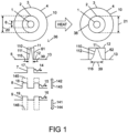
- Figure 1 shows an optical fibre 10 which has a first refractive index profile 61 that can be changed by heating to a second refractive index profile 62, the optical fibre 10 comprising at least one core 1, a cladding 3, at least one first dopant 7 for providing the first refractive index profile 61, at least one concealed dopant 8, and at least one mobile dopant 9, the core 1 having a refractive index 11 that is greater than a refractive index 13 of the cladding 3, and the core 1 having a first core diameter 6, the optical fibre 10 being characterized in that:
- the optical guidance property 39 of the optical fibre 10 is dependent on the optical wavelength 36, and is shown as the mode field diameter 115 of the optical mode 110, which increases after heating to the mode field diameter 116.
- the optical guidance property 39 may be the optical power distribution 111 of the optical mode 110 which has changed to the optical power distribution 112.
- the optical mode 110 may be the fundamental mode that is guided by the optical fibre 10.
- the mobile dopant 9 and the concealed dopant 8 are shown disposed in a doped region 2 surrounding the core 1. If the concealed dopant 8 were not present, the mobile dopant 9 would induce a refractive index change 146 to the first refractive index profile 61. Theoretically, the refractive index change 146 is equal to the product of the mobile dopant concentration 19 and the molar refractivity 144. The refractive index change 146 is balanced by the concealed dopant 8, which induces an equal and opposite refractive index change 145. Theoretically, the refractive index change 145 is equal to the product of the concealed dopant concentration 18 and the balancing molar refractivity 143.
- the net effect is to leave the first refractive index profile 61 induced by the first dopant 7 that is present in a first concentration 17 substantially unchanged.
- the refractive index 12 of the doped region 2 is equal to the refractive index 13 of the cladding 3.
- the refractive index change 145 is shown equal to the difference between the refractive index 11 of the core 1 and the refractive index 13 of the cladding 3. If the diffusion coefficient 16 of the mobile dopant 9 is much greater than the diffusion coefficient 15 of the concealed dopant 8 and the diffusion coefficient 14 of the first dopant 7, then if the fibre 10 is heated to a high enough temperature, the mobile dopant 9 will diffuse completely through the fibre 10 revealing the presence of the refractive index change 145 induced by the concealed dopant 8. The result is the creation of a core 38 comprising the core 1 and the doped region 2. The core 38 has a diameter 21 that is substantially equal to the diameter 20 of the doped region 2 prior to heating.
- the core diameter 21 can be 10% to at least 1000% times larger than the first core diameter 6.
- the optical fibre 10 enables fibres with substantially different core sizes to be spliced together without necessitating tapering the outside of one or both of the fibres, or using tapers that are spliced between the two fibres.
- the refractive index 12 of the doped region 2 will be higher than the refractive index 11 of the core 1, resulting in the second refractive index profile 62 shown in Figure 2 .
- second refractive index profiles 62 are therefore achievable corresponding to how much diffusion has been allowed to occur.
- a particular second refractive index profile 62 can be selected by determining the temperature and time that heat energy is applied to the fibre 10, or more typically, to different parts of the fibre 10.
- optical fibre fusion splicers can generally be programmed to deliver different temperatures over different times and in different regions along the core 1 and across the core 1 and the cladding 3.
- Optical fibre fusion splicers use flames, electric arcs, or lasers such as carbon dioxide lasers to apply heat to the fibre.
- the presence and the design of the disposition and concentration of the concealed dopant 8 make the present invention different and more flexible than prior art solutions.
- refractive index changes are achieved by diffusing the fluorine, a mobile dopant, into regions where much lower concentration of the fluorine is present. Large refractive index changes are only achievable by using very large concentrations of fluorine, such as 4 mol%.
- similar or larger changes in the refractive index and in the optical power distribution can be obtained using significantly lower concentrations of the mobile dopant 9 and by designing the disposition and concentration of the concealed dopant 8 in order to increase the refractive index as the mobile dopant diffuses upon heating.
- the present invention combines the effects of the refractive index changes 145 and 146 of the concealed and mobile dopants 8, 9, respectively. This simplifies the fabrication of the optical fibre preform due to the lower concentrations of mobile dopant required. It also allows better control of the disposition of the mobile dopant during the fabrication of the optical fibre and prior to the fibre being heated. Improved control of the rate of change of the refractive index profile is also achieved, improving the process reliability and reproducibility of components manufactured according to the present invention.
- the FoM is the root mean square of the change in the first refractive index profile 61 caused by heating, divided by the maximum concentration of the mobile dopant 9, and multiplied by the ratio of the maximum to the minimum of the mode field diameter 115 before heating and the mode field diameter after heating 116.
- the averaging for the root mean square is performed over a cross-sectional area (not shown) having a diameter that is twice the maximum of the mode field diameters 115 and 116.
- n1 and n2 are the first and second refractive indices 61 and 62 of the optical fibre 10 before and after heating
- MFD max and MFD min are the largest and smallest of the mode field diameter 115 prior to heating and the mode field diameter 116 after heating
- C SiO 1.5 F is the maximum of the concentration 19 of the mobile dopant 9 (in mol%) in the optical fibre 10 prior to heating.
- the FoM will be calculated and discussed in the Examples.
- Table 1 shows the molar refractivities for dopants commonly used in optical fibre manufacturing using silica glass.
- the molar refractivities are shown as the change in refractive index per mole percent of dopant ( ⁇ n/mol%).
- ⁇ n/mol% of germania raises the refractive index of silica by 0.0015.
- Oxides of germanium, phosphorus, aluminium, and lanthanides such as cerium and ytterbium raise the refractive index of silica.
- the molar refractivities shown assume the dopant is incorporated into pure silica.
- the molar refractivity can alter.
- aluminium phosphate depresses the refractive index of silica when the ratio of the concentrations of the aluminium ion to the phosphorus ion is one to one.
- concentration 18 of the concealed dopant 8 that is required to balance the refractive index change 146 induced by the mobile dopant 9.
- Optical fibres can be manufactured by depositing layers of glass and dopants along the inside of a glass capillary, and then collapsing the glass capillary to form a solid optical fibre preform. The optical fibre is then drawn from the optical fibre preform and a plastic coating added during the fibre drawing process. Dopant diffusion and evaporation can occur during deposition and collapse of the capillary resulting in ripples and other variations in refractive indices across the fibre cross section.
- the refractive indices referred to herein are meant to mean the average refractive index over certain named cross-sections.
- the refractive index 11 in Figure 1 is meant to mean the average refractive index over the cross sectional area of the core 1.
- the refractive index 12 is meant to mean the average refractive index over the cross sectional area of the doped region 2.
- the cladding 3 is made from a glass 4 having a refractive index 5. At least the outside region of the cladding 3 is usually made from silica glass or synthetic silica glass. Synthetic silica capillaries typically comprise chlorine and thus have a higher refractive index 5 than pure silica capillaries. Dopants are often added to the deposited glass layers within synthetic silica capillaries to compensate for this higher refractive index. As will be shown in the Examples, the first dopant 7 that provides the first refractive index profile 61 in Figure 1 would therefore include the chlorine dopant and any dopants added to compensate for the chlorine if a synthetic silica capillary is used in the manufacture of the optical fibre 10.
- Figure 3 shows the diffusion coefficients of chlorine 171, fluorine 172, and oxides of aluminium, 173, ytterbium 174, cerium 175, boron 176, germanium 177, and phosphorus 178 in silica.
- the diffusion coefficients of oxides of aluminium, ytterbium, and cerium are believed to be the same.
- the diffusion coefficients have been plotted assuming a 1 mol% dopant concentration for each of the dopants in pure silica.
- the diffusion coefficients for aluminium, 173, ytterbium 174, cerium 175, boron 176, germanium 177, and phosphorus 178 increase with increasing dopant concentration.
- the diffusion coefficients above relate to diffusion of ions through binary silica glass systems, that is systems comprising silica and the dopant. Diffusion through softer glasses, such as silica doped with phosphorus pentoxide, is faster than diffusion through silica, as shown by the diffusion coefficient 179 of fluorine in silica glass doped with phosphorus pentoxide. It can therefore be advantageous to add phosphorus pentoxide to the core 1 and the doped region 2 of the optical fibre 10 in order to reduce the time needed for the diffusion to take place.
- the optical fibre 10 enables a splice 29 to be made to a second optical fibre 22 having a core 27 with a core diameter 28 that is larger than the first core diameter 6.
- Figure 4 shows the optical fibre 10 spliced to a second optical fibre 22 and to a third optical fibre 23.
- the third optical fibre 23 has a core 24 with a core diameter 25 that is equal to the first core diameter 6 of the optical fibre 10.
- the optical fibre 10 and the third optical fibre 23 can be fusion spliced together to form the splice 26 using an optical fibre fusion splicer. Low loss (less than 0.15dB) splices are readily achievable.
- the second optical fibre 22 has a cladding 35 surrounding the core 27.
- the core 27 has a core diameter 28 that is larger than the first core diameter 6 of the optical fibre 10. It is therefore necessary to allow the mobile dopant 9 to diffuse into the core 1 of the optical fibre 10 and reveal the presence of the concealed dopant 8 in order to expand the core 1 of the optical fibre 10 such that its effective core diameter 32 matches the core diameter 28 at the fusion splice 29.
- a fusion splicer can be positioned such that it provides an arc, a flame, or a laser beam over a splicing region 30, with the highest temperature within the arc, flame or laser beam at the fusion splice 29.
- the temperature falls either side of the fusion splice 29.
- the diffusion rate of the mobile dopant 9 decreases with falling temperature, thus decreasing the amount of diffusion of the mobile dopant 9 that occurs either side of the fusion splice 29. This variation in diffusion results in a taper 31 of the effective core diameter 32 of the optical fibre 10.
- the variation in diffusion can also be achieved by moving the fibre 10 and the second optical fibre 22 with respect to the position of the arc, flame or laser beam and changing either the temperature or the time the arc flame or laser beam remains at each position within the taper region 31.
- the length 33 of the taper 31 is determined by the design of the fusion splicer and in particular in how much relative movement can be achieved with the fibre 10, but is typically in the range 1mm to 5mm. The length 33 can be longer than 5mm or shorter than 1mm.
- the effective core diameter 32 is preferably equal to the core diameter 28 of the second optical fibre 22 at the splice 29. Properties of the taper 31 at distances 34 from the splice 29 will be discussed with reference to the Examples.
- the first dopant 7 may be the same as the concealed dopant 8.
- both the first dopant 7 and the concealed dopant 8 may comprise germania.
- the concentration 17 of the first dopant 7 in the core 1 may be less than the concentration 18 of the concealed dopant 8.
- the first and the concealed dopants 7, 8 are germania, and the mobile dopant 9 is fluorine, then the refractive index 11 of the core 1 will reduce more quickly than if the concentration 17 were less than the concentration 18. This enables splices to be made more quickly than if the concentration 17 of the first dopant 7 in the core 1 were equal to or greater than the concentration 18 of the concealed dopant 8. It has been found that splices that can be made more quickly are more reliable.
- Figure 5 shows dopant concentration 40 in mole percent versus radius 45 in microns for an optical fibre 50.
- the optical fibre 50 is an example of the optical fibre 10 of Figure 1 .
- the first dopant 7 and the concealed dopant 8 both comprise germania.
- the first dopant 7 also includes phosphorus and chlorine.
- the germania concentration 41 had the first dopant concentration 17 in the core 1, and the concealed dopant concentration 18 in the doped area 2, which concealed dopant concentration 18 was larger than the first dopant concentration 17.
- the cross-sectional area containing the concealed dopant 8 is more than five times the cross sectional area of the core 1.
- the mobile dopant 9 was fluorine.
- the fluorine concentration 42 had a mobile dopant concentration 19 in the doped area 2.
- the cladding 3 is made from a synthetic silica glass substrate tube into which the glass layers of the core 1 and doped region 2 were deposited during fibre manufacture.
- the glass 4 was silica glass having a chlorine concentration 44 in the cladding 3.
- the optical fibre 50 was also doped with phosphorus pentoxide which had a phosphorus pentoxide concentration 43 in the core 1 and the doped area 2. The phosphorus pentoxide was added in order to increase the diffusion rates of the mobile dopant 9, and to raise the refractive index of the glass layers that were deposited during manufacture in order to compensate for the chlorine dopant.
- the germania concentration 41 and the phosphorus pentoxide concentration 43 showed a dip at a radius 45 equal to zero, corresponding to the centre of the optical fibre 50.
- This dip is characteristic of optical fibres made from modified chemical vapour deposition (MCVD), and is caused by germania and phosphorus pentoxide evaporating during the high temperature (2000C) collapse of the capillary from which the optical fibre preform is made.
- MCVD modified chemical vapour deposition
- Other optical fibre manufacturing processes, such as outside vapour deposition (OVD) and vapour-phase axial deposition (VAD) do not typically result in such dips in the dopant concentrations.
- the concentrations of the dopants are shown in Table 2, together with the chemical formula of the functional unit.
- concentration of fluorine is measured as the mole percentage of SiO 1.5 F.
- the calculated first refractive index profile 61 shown by the dashed line in Figure 9 , was obtained from the molar refractivities in Table 1 and the concentrations in Table 2.
- the concentrations are compared in the table with an equivalent fibre 60, shown with reference to Figure 6 , that has the same first refractive index profile 61, but without the additional mobile dopant 9 and concealed dopant 8.
- the germania concentration 41, the phosphorus pentoxide concentration 43 and the chlorine concentration 44 are the same in the core 1 and the cladding 3 as for the optical fibre 50 described with reference to Figure 5 .
- the germania concentration 41 in the doped region 2 has been reduced to 0 mol%.
- the fluorine concentration 42 is 0.057 mol %, representing a reduction by a factor of 10.5 from the 0.6 mol% fluorine of the optical fibre 50.
- the core delta ⁇ 147 is an important guidance parameter in optical fibres, and is the difference in the refractive index 11 of the core 1 and the refractive index 13 of the cladding 3.
- the core delta ⁇ 147 is approximately 0.002.
- the germania concentration 41 is 1.9 mol% in the doped region 2, which is higher than the 1.4 mol% germania concentration 41 in the core 1.
- the fluorine concentration 42 of 0.6 mol% is substantially higher than the 0.057 mol% of the optical fibre 60 that has the same first refractive index profile 61 as the optical fibre 50.
- the mobile dopant 9 in the optical fibre 50 is fluorine.
- the fluorine concentration 42 of 0.6 mol% represents an additional 0.543 mol% compared to the fluorine concentration 42 in the equivalent optical fibre 60 that has the same first refractive index profile 61.
- the mobile dopant concentration 19 is therefore 0.543 mol%.
- Such a fluorine concentration would depress the refractive index 5 of the glass 4 in the doped region 2 by a refractive index change 146, shown with reference to Figure 1 , of 0.00315.
- the refractive index change 146 is over 50% larger than the core delta ⁇ 147 of 0.002 shown with reference to Figure 10 .
- Such a refractive index change 146 would more than double the refractive index difference between the core 1 and the doped region 2 which would dramatically modify the guidance properties 39 of the optical fibre 10 were it not for the presence of the concealed dopant 8. It was therefore necessary to use a germania concentration 41 of 1.9% to compensate or balance the refractive index change 146 induced by the fluorine.
- the diffusion coefficient 172 of fluorine is higher than the diffusion coefficient 177 of germania.
- the diffusion coefficient 179 of fluorine in silica doped with phosphorus pentoxide, as used in the optical fibre 50, is even higher.
- Each of the balancing and the mobile dopants 8, 9 are present at significantly higher concentrations than required to obtain the first refractive index profile 61.
- FIG. 7 shows the results of a computer simulation of the dopant concentrations.
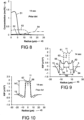
- the germania concentration 51, fluorine concentration 52, phosphorus pentoxide concentration 53, and chlorine concentration 54 after diffusing at a temperature of 2050C for 14 seconds are shown by the solid lines. Fluorine has diffused from the doped region 2 into the core 1. The initial fluorine concentration 41 was zero in the core 1.
- Chlorine also diffused in the results shown in Figures 7 and 8 .
- the chlorine concentration 54 is substantially the same in each case.
- Figure 9 shows the calculated first refractive index profile 61 of the optical fibre 50 before heating (dashed line), and the calculated first refractive index profile 62 at 25C after heating to 2050C for 14 seconds (solid line).
- the refractive index profile 61 has been level shifted such that zero represents the third refractive index 13 of the cladding 3.
- the same approach was taken with other refractive index profiles described herein.
- the first refractive index profile 61 has a refractive index dip 63 caused by evaporation of the germania and phosphorus pentoxide during the preform collapse.
- the core 1, the doped region 2, and the cladding 3 are clearly visible.
- the doped region 2 is a depressed cladding 65 which is slightly depressed in refractive index with respect to the refractive index 13 of the cladding 3.
- the refractive index profile 62 has a depressed cladding region 64 owing to diffusion of fluorine from the doped area 2 into the cladding 3.
- Heating at 2050C for 14 seconds has reduced the refractive index 11 of the core 1 and increased the refractive index 12 of the doped region 2 resulting in a core 66 having a core diameter 69 that is greater than the first core diameter 6 prior to heating.
- Figure 10 shows the calculated refractive index profile 67 of the optical fibre 60 before heating (dashed line) and the calculated refractive index profile 68 after heating (solid line) to 2050C for 14 seconds.
- the core 1 has diffused slightly, but substantially less than for the optical fibre 50.
- Figure 11 shows the calculated optical power distributions 111, 112, 113, 114, normalized to unity, for the fundamental modes 110 supported by the refractive index profiles 61, 62, 67 and 68 respectively.
- the optical power distributions 111 and 113 overlay each other confirming that the refractive indices 61 and 67 provide the same optical power distributions.
- the optical power distribution 112 of the optical fibre 50 after heating is much wider than the optical power distribution 111 before heating.
- the optical power distribution 114 of the optical fibre 60 after heating is nearly the same as the optical power distribution 113 before heating.
- the increase in the size of the optical power distribution induced by heating for 14 seconds is evidently very much greater for the optical fibre 50 of Figure 5 than for the optical fibre 60 of Figure 6 .
- Table 3 shows calculated values of effective mode area, the mode field diameter, and beam quality of the pristine fibres (before heating) and the diffused fibres (after heating) for the fundamental modes 110 supported by the optical fibres 50 and 60.
- the mode field diameters 115, 116 before and after heating are shown in Figure 1 .
- the effective mode area has increased by a factor of 4.8, the mode field diameter by 2.1, and there has been a negligible degradation in beam quality M 2 value.
- Incorporating the balancing and mobile dopants 8, 9 into the optical fibre 50 has resulted in a significant increase in mode field diameter compared to the optical fibre 60.
- the optical fibre 60 would need to be heated for much longer than 14 seconds, and tapers or intermediate fibres used in a low loss splice to another fibre having a mode field diameter of approximately 22.5 ⁇ m.
- Table 3 also includes the values of the figure-of-merit FoM calculated in accordance with Equation 1 for the optical fibres 50 and 60.
- the FoM value of 225.2 for optical fibre 50 is significantly higher than has been obtainable with the prior art. This demonstrates that inclusion of the concealed dopant 8 enables much larger changes in mode field diameter 115 for similar concentrations of fluorine, or alternatively, much smaller concentrations of fluorine are required to achieve the same changes in mode field diameter 115.
- the optical fibre 50 was manufactured according to the design described with reference to Figures 5 and 9 .
- Figure 12 shows the measured refractive index profile 71 before heating (dashed line), and the measured refractive index profile 72 at 25C after heating in a fusion splicer to 2050C for 14 seconds (solid line) of the optical fibre 50.
- a refractive index dip 73 is present, as expected from Figure 7 .
- Heating at 2050C for 14 seconds has caused fluorine to diffuse from the doped region 2 into the core 1, thus reducing the refractive index 11 of the core 1, and increasing the refractive index 12 of the doped region 2.
- Fluorine has also diffused into the cladding 3, leading to a depressed refractive index region 74.
- the calculated refractive index profiles 61, 62 are very similar to the measured refractive index profiles 71, 72 thus validating the theoretical analysis method.
- the optical fibre 50 was used in place of the optical fibre 10.
- the optical fibre 50 was designed to provide a low loss fusion splice 29 with the optical fibre 22.
- the optical fibre 22 had the core diameter 28 equal to approximately 25 ⁇ m.
- the core diameter 6 of the optical fibre 50 was approximately 10 ⁇ m, which is smaller than the core diameter 28 of the second optical fibre 22.
- the optical fibre 22 was an active fibre, with the core 27 being doped with oxides of cerium, ytterbium, and aluminium.
- FIG 13 shows the measured refractive index profile (RIP) 84 before heating (dashed line), and the measured refractive index profile 85 at 25C after heating (solid line) to 2050C for 11 seconds for the second optical fibre 22.
- the second optical fibre 22 had a core 81 that is doped with oxides of aluminium, cerium and ytterbium, a pedestal 82 that is doped with germania, and a silica cladding 83.
- the pedestal 82 is a raised refractive index cladding.
- the core 81 can support a fundamental mode that is guided against the pedestal 82.
- the second optical fibre 22 was not made using modified chemical vapour deposition (MCVD) and thus there is no refractive index dip 73 at the centre, where the radius 45 equals zero.
- MCVD modified chemical vapour deposition
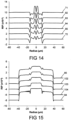
- FIG 14 shows refractive index profiles 71, 92, 93, 94, 95 and 72 of the optical fibre 50 measured at distances 34 from the splice 29 defined in Figure 4 .
- the refractive index profiles are shown offset from each other for clarity.
- the distances 34 corresponding to Figures 71, 92, 93, 94, 95 and 72 were 800 ⁇ m, 450 ⁇ m, 350 ⁇ m, 200 ⁇ m, 100 ⁇ m and 20 ⁇ m respectively.
- the refractive index profiles 71 and 72 were previously discussed with reference to Figure 12 .
- Figure 15 shows refractive index profiles 85, 102, 103, 104 and 84 measured at distances 20 ⁇ m, 200 ⁇ m, 300 ⁇ m, 400 ⁇ m and 800 ⁇ m from the splice 29 in the second optical fibre 22.
- the refractive index profiles are shown offset from each other for clarity.
- the core diameter 32 of the optical fibre 50 expands along the taper 31.
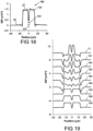
- Figure 16 shows the refractive index 72 superimposed on the refractive index 85 after adjusting for differences in absolute refractive index.
- the core diameter 69 of the optical fibre 50 after heating is substantially equal to the core diameter 28 of the second optical fibre 22.
- the mode field diameter 115 and the effective mode area 121 (shown with reference to Figure 17 ) which can be measured using industry standard instrumentation, or calculated from the refractive index profiles shown in Figures 14 and 15 .
- the mode field diameter 115 has been taken as the beam diameter as defined in the international standard BS EN ISO 11146-1:2005 (formula 23) by computing the second order moment of the mode distribution.
- the mode field diameter 115 gives a meaningful measure of the size of the mode, and is particularly useful for estimating splice losses when joining two fibres together.
- the effective mode area 121 is a measure of the area over which the power of the mode is distributed. It is particularly useful to determine how much power the core can carry without causing non-linear type signal losses.
- the effective mode area is further described in Agraval "Nonlinear fiber optics", Academic Press, page 44 , formula 2.3.29.
- the concepts of mode field diameter 115 and effective mode area 121 can be adapted to fibres regardless of their refractive index profiles, and are thus widely used in the industry.
- Figure 17 shows the effective mode area 121 as a function of the distance 34 from the splice 29 shown in Figure 4 . Negative values of the distance 34 correspond to the optical fibre 50, and positive values of the distance 34 correspond to the second optical fibre 22.
- Figure 17 shows that the effective mode area 121 increased from approximately 90 ⁇ m 2 to approximately 300 ⁇ m 2 at the splice 29. This increase was induced by heating the optical fibre 50 for 11 seconds at 2050C, at which time the fusion splicer was switched off. As shown in Table 3, if the heating had been continued, the effective mode area 121 would have increased further to approximately 400 ⁇ m 2 .
- the increase in the effective mode area 121 is gradual, which is advantageous in that a gradual increase results in an adiabatic taper.
- Adiabatic tapers have lower losses and lower conversion to higher order modes than non-adiabatic tapers.
- the fusion splice 29 between the optical fibre 50 and the second optical fibre 22 is such that the effective mode areas 121 of the optical fibre 50 and the second optical fibre 22 are equal at the splice 29.
- the design of the optical fibre 50 is shown to allow low loss splicing between fibres with significantly different core diameters and different effective areas without the need for tapering the diameter of the fibre cladding 3. This may simplify the manufacturing process of a laser based on the optical fibre 50 because no tapering equipment is required to launch into the large core laser delivery fibres that are typically required to reduce optical non-linearities.
- the design of the optical fibre 50 does not require extremely large concentrations of the mobile dopant 9 (fluorine) to be incorporated in the fibre, such as the 4 mol% fluorine concentration described in United States Patent No. 6,690,868 .
- the lower fluorine concentration of this Example thus simplifies the fibre manufacturing process and makes the diffusion process more reliable. It also reduces the duration of the heat treatment to achieve the required diffusion for a given concentration of the mobile dopant 9, which is especially beneficial for changes in core diameter 6 of at least 2 times is desired.
- the second optical fibre 22 used in this example was a passive optical fibre 180 shown in Figure 18 .
- the optical fibre 10 was the optical fibre 50 of Figures 5 and 12 and Example 1.
- the optical fibre 180 had the core diameter 28 equal to approximately 25 ⁇ m.
- the optical fibre 180 was a passive fibre comprising no rare-earth dopant.
- the core 27 was doped with germania, resulting in a core comprising germanium doped silica.
- Figure 18 shows the measured refractive index profiles (RIP) 134 before heating (dashed line) of the optical fibre 180.
- the core 27 includes a refractive index dip 137 at the centre, which dip is typical of optical fibres made from modified chemical vapour deposition (MCVD).
- MCVD modified chemical vapour deposition
- the measured refractive index profile 135 was measured at 25C after heating (solid line) to 2050C for 14 seconds.
- the refractive index profiles 134 and 135 are very similar indicating that there is significantly less diffusion occurring in the optical fibre 180 than occurred with the optical fibre 50 of Figure 12 .
- Figure 19 shows the measured refractive index profiles 71, 191, 192, 193, 194, 195 measured in the optical fibre 50 of Figure 12 at distances 34 of -800 ⁇ m, -420 ⁇ m, -320 ⁇ m, -220 ⁇ m, -120 ⁇ m, and -20 ⁇ m from the splice 29, and the measured refractive index profiles 135, 196, 134 measured in the optical fibre 180 of Figure 18 at distances 34 of 20 ⁇ m, 200 ⁇ m, and 500 ⁇ m from the splice 29.
- the refractive index profiles have been level shifted for clarity.
- Figure 20 shows an overlay of the refractive index profiles 135 (dashed line) and the refractive index profile 195.
- the refractive index profiles 135, 195 substantially overlay each other in the region of the core 27 of the fibre 180.
- Figure 21 shows the effective mode area 161 versus the distance 34 from the splice 29 that was calculated from the measured refractive index profiles such as those shown in Figure 19 .
- the effective mode areas 161 of the fundamental modes of the optical fibre 50 and the second optical fibre 180 are substantially equal at the distance 34 equal to zero, corresponding to the splice 29 shown in Figure 4 .
- the effective mode area 161 of the fundamental mode of the second optical fibre 180 changes very little within the splice region 30.
- the effective mode area 161 at the splice 29 was approximately 390 ⁇ m 2 , which is slightly more than in Figure 17 .
- the larger effective mode area was achieved by heating the optical fibres for slightly longer while splicing.
- a fibre designed according to this example may be used to launch into a passive fibre with much larger core diameter 28 in order to reduce the effect of optical non-linearities in high power lasers.
- the taper 31 can be made adiabatic in order to achieve low losses, which are important in high power lasers for power budget and laser reliability.
- An adiabatic taper is also useful to ensure low loss coupling from the fundamental modes without resulting in coupling to higher order modes.
- a splice loss less than 0.5dB is readily achievable while preserving a beam quality M 2 ⁇ 1.2. This is particularly important in case the second optical fibre 22 is a multi-mode fibre.
- Figure 22 shows a design of an optical fibre 220 that is similar to the optical fibre 50 of Figure 5 , but where the fluorine concentration 42 has been increased from 0.6 mol% to 1 mol%.
- the germania concentration 41 in the doped region 2 was increased to offset the depression in the refractive index 5 induced by the fluorine.
- the germania concentration 41 was 3.55 mol% in the doped region 2, and 1.75 mol% in the core 1, which corresponds to a concentration ratio of the concealed dopant (germania) concentration 18 in the doped area 2 to the first dopant concentration 17 of the first dopant 7 (germania) in the core 1 of approximately two.
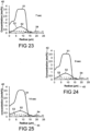
- Figures 23 to 25 show the calculated germania concentration 51, fluorine concentration 52, phosphorus pentoxide concentration 53, and chlorine concentration 54 after diffusing at a temperature of 2050 C for 7, 9, 14 seconds respectively.
- the initial fluorine concentration 41 was zero in the core 1.
- the amount of fluorine diffusing out of the doped area 2 and into the core 1 increases with time.
- Figures 26 to 28 show the first refractive index profile 61 (dashed line) and the second refractive index profiles 62 (solid line) corresponding to the diffused dopant profiles shown in Figures 23 to 25 .
- the refractive index 11 of the core 1 reduces with time that heat is applied, and the refractive index 12 of the doped region 2 increases with time.
- the corresponding optical power distributions 111, 112 are shown in Figures 29 to 31 , and the calculated mode field parameters are shown in Table 4.
- a fundamental doughnut mode can be coupled into either a ring core fibre, or a multimode optical fibre. If the multimode optical fibre is such that its optical modes are not coupled together, the multimode optical fibre can deliver a ring-shaped power distribution to a work piece via a focussing system.
- Table 4 Calculated mode field parameters and figure of merit (FoM) for the results shown in Figures 26 to 31.
- the changes in beam quality M 2 reported in Table 4 are much greater than obtained by prior art fibre designs, and are achieved by simple heat treatment of the optical fibre 220 in order to obtain the taper 33 of Figure 4 .
- the heat treatment enabled the optical power distribution 111 of the fundamental mode having a Gaussian distribution to be converted to an optical power distribution 112 of the fundamental mode that had a triangular, flat top, and then doughnut power distributions. These were all achieved with an adiabatic transition and therefore low loss and low conversion to higher order modes.
- the ability to provide such large changes in the M 2 value by heating is an advantage of the present invention.
- the optical fibre 10 may have a fundamental mode defined by an M 2 value prior to heating less than 1.15, and a fundamental mode defined by an M 2 value after heating that is at least 1.2.
- the M 2 value after heating may be at least 1.3.
- the M 2 value after heating may be at least 1.5.
- the M 2 value is a measure of the beam quality, an M 2 value of 1.0 corresponding to a Guassian beam.
- the M 2 value is a measure of the shape of the fundamental mode, the higher the M 2 value, the less Gaussian the mode.
- Figure 32 shows an optical fibre 320 that is designed to reduce the effective first diameter 6 of the core 1 upon heating.
- the optical fibre 320 comprises the core 1, a pedestal 181, and the cladding 3.
- the pedestal 181 comprises an optional inner pedestal 182, the doped region 2, and outer pedestal 183.
- Figure 34 shows the first refractive index profile 61 before heating. The concentrations of the dopants are shown in Table 5, together with the chemical formula of each functional unit.
- Figure 33 shows the dopant concentration 40 in mole percent versus radius 45 in microns.
- the glass 4 was silica.
- the first dopant 7, required to obtain the first refractive index profile 61 of Figure 34 comprised germania, alumina, chlorine, and oxides of ytterbium, and cerium.
- the ytterbium concentration 185 was the same as the cerium concentration 186.
- the alumina concentration 184 was higher than the ytterbium concentration 184 and the cerium concentration 185.
- the glass 4 was silica glass having a chlorine concentration 44 in the cladding 3.
- the germania concentration 41 comprised a concentration 187 of 2 mol% throughout the pedestal 181 representing the first dopant concentration 17 in the pedestal 181.
- the mobile dopant 9 was fluorine.
- the fluorine concentration 42 had the mobile dopant concentration 19 in the doped region 2.
- the concealed dopant 8 was germania.
- the germania concentration 41 of 5 mol% in the doped region 2 comprised the concentration 187 of 2 mol% plus the concealed dopant concentration 18 of 3 mol% that was required to balance the refractive index change 146 induced by the mobile dopant 9.
- Table 5 Dopant Concentrations Location Dopant Chemical Formula Concentration Core Alumina GeO 2 1.2 mol% Core Ytterbium Yb 2 O 3 0.15 mol% Core Cerium CeO 2 0.1 mol% Inner pedestal Germania GeO 2 2.0 mol% Doped region Germania GeO 2 5.0 mol% Doped region Fluorine SiO 1.5 F 0.86 mol% Outer Pedestal Germania GeO 2 2.0 mol% Cladding Chlorine SiO 1.5 Cl 0.2 mol%
- Figure 34 shows the calculated first refractive index profile 61 before heating.
- the first refractive index profile 61 is offset by the refractive index 13 of the cladding 3, which was synthetic silica comprising chlorine doped glass.
- the first refractive index profile 61 was calculated by multiplying the dopant concentrations shown in Figure 33 with the respective molar refractivities shown in Table 1.
- the core 1 has a refractive index 11 which is higher than the refractive index 201 of the pedestal 181.
- the refractive index 201 of the pedestal 181 is higher than the third refractive index 13 of the cladding 3.
- the balancing and mobile dopant concentrations 18, 19 in the doped region 2 are selected such the refractive index 12 of the doped region 2 is substantially the same as the refractive index 201 of the pedestal 181 outside the doped region 2.
- the refractive index 201 of the pedestal 181 is substantially uniform.
- the core 1 guides against the pedestal 181, and thus the effective core delta ⁇ 147 is the difference between the core refractive index 11 and the pedestal refractive index 201.
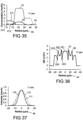
- Figure 37 shows the optical power distribution 111 of the fundamental mode 110 guided by the core 1 before heating.
- Figure 35 shows the calculated germania concentration 51, fluorine concentration 52, chlorine concentration 54, alumina concentration 211, ytterbium concentration 212 and cerium concentration 213 after heating at 2050C for 11 seconds.
- the fluorine has diffused more than the germanium, alumina, ytterbium and cerium.
- Figure 36 shows the calculated first refractive index profiles 61 before heating (dashed line), and the calculated second refractive index profile 62 at 25C after heating at 2050C for 11 seconds.
- Diffusion of the fluorine from the doped region 2 into the core 1 has caused the refractive index 11 of the core 1 of the optical fibre 320 prior to heating to reduce in at least a portion of the core 1.
- the resulting profile 62 of the heated fibre has a smaller core 221 than the core 1 of the fibre 320 prior to heating.
- the diffusion of the fluorine from the doped region 2 has also caused refractive index peaks 222 and refractive index depressions 223 in the pedestal 181.
- Figure 37 shows the optical power distribution 111 of the fundamental mode 110 supported by the optical fibre 320 prior to heating, and the optical power distribution 112 after heating.
- the optical power distribution 111 has a mode field area of 390 ⁇ m 2 before heating, and the optical power distribution 112 has a mode field area of 233 ⁇ m 2 after heating.
- the fundamental mode 110 has a beam quality defined by an M 2 value equal to 1.02 prior to heating, and a beam quality defined by an M 2 value equal to 1.09 after heating.
- the optical fibre 320 can be used to splice to a second optical fibre that has a mode field diameter that is less than the mode field diameter 115 of the optical fibre 320.
- the refractive index peaks 222 and the refractive index depressions 223 will only occur where the optical fibre 320 has been heat treated and will have little detrimental effect provided that the transition from the first refractive index profile 61 to the second refractive index profile 62 is adiabatic.
- the figure-of-merit FoM for the optical fibre 320 is equal to 30.9.
- the optical fibre 320 can be spliced to an optical fibre like the optical fibre 50 described in Figure 5 . It is possible to achieve an increase the effective area of the fundamental mode from 87um 2 (as from Table 3) to 925um 2 by properly scaling the core diameter of optical fibre 320 up to 42.5um in a single splice and without any tapering of the fibre cladding diameter. This is an increase in mode field diameter from 10.6um to 36.1um.
- Figure 38 shows the dopant concentration 40 for an optical fibre 380 designed to reduce the mode field diameter 115 of the fundamental mode 110 upon heating.
- the core 1 is a step index core comprising an outer core 381 and the doped region 2 which have substantially the same refractive index 11.
- the first and concealed dopants 7, 8 were germania, and the mobile dopant 9 was fluorine.
- the design was based on a fibre made with a synthetic silica capillary, and thus the cladding 3 at radii greater than 15 ⁇ m is made primarily from silica doped with chlorine. Phosphorus pentoxide has been added at radii less than 15 ⁇ m in order to compensate for the chlorine.
- the phosphorus pentoxide doping may also increase the diffusion rate of the fluorine dopant upon heating.
- the germania concentration 41 is raised for radii less than 5 ⁇ m compared to radii between 5 ⁇ m and 10 ⁇ m in order to compensate for the refractive index change 146 induced by the fluorine concentration 42 at radii less than 5 ⁇ m.
- the germania, fluorine, phosphorus, and chlorine concentrations 41, 42, 43, 44 are shown in Table 6, save that the central refractive index dip and concentration gradients have been ignored for clarity. Also shown are the dopant concentrations for a fibre with the same first refractive index profile 61, shown with reference to Figure 40 , but without the mobile dopant 9, fluorine.
- the 3.9 mol% concentration of the germania concentration 41 in the doped region 2 thus represents the first dopant concentration 17 of 1 mol% required to achieve the first refractive index profile 61, plus an additional concealed dopant concentration 18 of 2.9mol% required to balance the refractive index change 146 induced by the mobile dopant 9.
- Figure 39 shows the germania, fluorine, phosphorus pentoxide, and chlorine concentrations 51, 52, 53, 54 after heating the fibre for 19 seconds at 2050C.
- Figure 40 shows the first refractive index profile before heating 61 and the second refractive index profile 62 after heating. Fluorine has diffused out of the doped region 2 into the outer core 381. The refractive index 12 of the doped region 2 has risen, and the refractive index 11 of the outer core 381 has fallen.
- Figure 41 shows the optical power distribution 111 of the fundamental mode 110 before heating and the optical power distribution 112 of the fundamental mode 110 after heating.
- the parameters of the fundamental mode 110 before and after heating are given in Table 7, together with the figure-of-merit FoM for this design.
- the effective mode area of the fundamental mode 110 has reduced from 267 ⁇ m 2 to 84 ⁇ m 2 .
- the optical fibre 380 can be used to splice to a second optical fibre that has a mode field diameter that is less than the mode field diameter 115 of the optical fibre 380.
- the figure-of-merit FoM is in excess of 150 for the fibre of Figure 38 , which is greater than can be obtained from prior art approaches.
- the optical fibre 380 is an example of a beam delivery fibre for high power lasers which has a large core diameter in order to reduce optical non-linearities such as Raman scattering and four wave mixing.
- the optical fibre 380 can be spliced with low loss to a smaller core optical fibre such as the optical fibre 23 in Figure 4 without requiring tapering of the cladding diameter.
- a further benefit of the optical fibre 380 as a delivery fibre is that a smaller core diameter may be required at the output of a laser to increase the divergence of the output beam and reduce the power density in the processing optics. Heating of the optical fibre 380 at its output can reduce its core diameter.
- optical fibre 380 can be spliced to the optical fibre 50 described with reference to Figure 5 .
- the core diameter of optical fibre 50 increases when heated.
- the core diameter of optical fibre 380 becomes smaller when heated.
- splicing the enlarged core of optical 50 to the reduced core of optical fibre 380 allows an even larger transformation of the mode field diameter within a single splice. Additionally or alternatively, a shorter splice can be made that is more reliable as the transition is shared between the two optical fibres.
- Figure 42 shows an optical fibre 420 which is similar to the optical fibre 380 of Figure 38 .
- the optical fibre 420 includes a second doped region 421 between radii of 10 ⁇ m and 15 ⁇ m.
- the fluorine concentration 42 has a dopant concentration 423 of 0.55 mol% and the germanium concentration 41 has a concentration 422 of 1.9 mol% in the second doped region 421.
- the concealed dopant concentration 18 in the second doped region 421 is the germanium concentration 422, which was selected to balance the refractive index change 146 induced by the mobile dopant 9, fluorine, in the second doped region 421.
- the concealed dopant concentration 18 in the doped region 2 is the same as for the optical fibre 380 of Figure 38 .
- Figure 43 shows germania, fluorine, phosphorus pentoxide, and chlorine concentrations 51, 52, 53, 54 after heating the fibre 420 for 14 seconds at 2050C.
- Figure 44 shows the first refractive index profile 61 before heating and the second refractive index profile 62 after heating. Fluorine has diffused out of the doped regions 2, 421 into the outer core 381.
- the refractive indices 12, 444 of the doped regions 2, 421 have risen to the refractive indices 443 and 441 respectively.
- the refractive index 11 of the outer core 381 has fallen to the refractive index 442.
- the difference between the refractive index 443 and the refractive index 13 of the cladding 3 after heating is approximately twice that of the difference between the refractive index 11 of the core 1 and the refractive index 13 of the cladding 3 before heating.
- Figure 45 shows the optical power distribution 111 of the fundamental mode 110 before heating and the optical power distribution 112 of the fundamental mode 110 after heating.
- the parameters of the fundamental mode 110 before and after heating are given in Table 7, together with the figure of merit (FoM).
- the effective mode area of the fundamental mode 110 has reduced from 265 ⁇ m 2 to 84 ⁇ m 2 .
- the optical fibre 420 of Figure 42 provides substantially the same reduction in the fundamental mode area after heating in 14 seconds compared to 19 seconds for the optical fibre 380 of Figure 38 . Reducing the time required to transform the optical mode parameters improves the reliability of optical fibre splices and other optical devices. The advantages discussed with reference to Example 6 apply to this Example.
- Figure 46 shows the dopant concentration 40 for an optical fibre 460 which is similar in design to the optical fibre 380 of Figure 38 , save that the core 1 and the doped region 2 of the fibre 460 overlap with each other.
- the optical fibre 460 is designed to increase the difference between the refractive index 11 of the core 1 and the refractive index 13 of the cladding 3 from 0.0024 to 0.0042 upon heating.
- the germania concentration 41 and the fluorine concentration 42 in the core 1 are 5.25 mol% and 1 mol% respectively.
- the cladding 3 comprises an inner cladding 461 doped with phosphorus pentoxide, and an outer cladding 3 that is synthetic silica comprising silica doped with chlorine.
- the phosphorus pentoxide concentration 43 is selected such that the refractive index 13 of the cladding 3 is approximately uniform.
- Phosphorus pentoxide is also selected as a dopant as it is believed to increase the diffusion coefficient 16 of fluorine, thereby reducing the time required to make a splice.
- Table 8 Dopant Concentrations Location Dopant Chemical Formula Concentration Concentration without use of Fluorine Difference in Concentration 0 to 5 ⁇ m Germania GeO 2 5.25 mol% 1.75 mol% 3.5 mol% 0 to 5 ⁇ m Fluorine SiO 1.5 F 1.00 mol% 0 mol% 1.00 mol% 0 to 5 ⁇ m Phosphorus Pentoxide P 2 O 5 0.25 mol% 0.25 mol% 0 mol% 5 to 15 ⁇ m Phosphorus Pentoxide P 2 O 5 0.25 mol% 0.25 mol% 0 mol% >15 ⁇ m Chlorine SiO 1.5 Cl 0.2 mol% 0.2 mol% 0 mol%
- Figure 47 shows germania, fluorine, phosphorus pentoxide, and chlorine concentrations 51, 52, 53, 54 after heating the fibre for 9 seconds at 2050C.
- Figure 48 shows the refractive index 61 before heating and the second refractive index 62 after heating 62.
- the refractive index 11 of the core 1 is the same as the refractive index 12 of the doped region 2 as the doped region 2 overlaps with the core 1. Fluorine has diffused out of the doped region 2 into the cladding 3.
- the refractive index 12 of the doped region 2 has risen.
- the refractive index 11 of the core 1 has also risen as the core 1 overlaps the doped region 2.
- the difference between the refractive index 11 of the core 1 and the refractive index 13 of the cladding 3 is higher after heating than before heating.
- Figure 49 shows the optical power distribution 111 of the fundamental mode 110 before heating and the optical power distribution 112 of the fundamental mode 110 after heating.
- the parameters of the fundamental mode 110 before and after heating are given in Table 9, together with the FoM for this design.
- the reduction in the effective mode area is caused by the increase in the difference between the refractive index 11 of the core 1 and the refractive index 13 of the cladding 3 induced by heating of the optical fibre 460.
- the increase in the refractive index 11 improves the guidance properties 39 of the optical fibre 460. This can be demonstrated by calculating the pure bend loss in a 40mm diameter bend.
- the bend loss calculated for one loop decreases by eight orders of magnitude, from 0.1 dB/loop to 9 ⁇ 10 -10 dB per loop.
- the fluorine concentration 42 of 1 mol% is substantially higher than would be required to produce the first refractive index profile 61 in Figure 48 .
- Table 8 shows the concentrations for an equivalent fibre having the same first refractive index profile 61 as the optical fibre 460, but without the fluorine dopant.
- the germania concentration 41 reduces to 1.75 mol%, which is a reduction in concentration by a factor of 1/3 over the concentration of 5.25 mol% used in the optical fibre 460.
- the concentration 17 of the first dopant 7 in the core 1 is 1.75 mol%.
- the balancing concentration 18 of the concealed dopant 8 is 3.5 mol%, which is a factor of two higher than the concentration 17.
- the concentration 19 of the mobile dopant 9 is 1 mol%.
- the figure-of-merit FoM of the optical fibre 460 is smaller than in previous examples, and is similar to the best values that we believe are achievable with prior art techniques. Nevertheless, standard fibre designs typically show an increase in bending sensitivity when heated, as thermally expanded cores have lower numerical aperture due to diffusion of the first dopant. The reduced bend sensitivity of fibre 460 upon heating makes this fibre advantageous for the manufacturing of optical components where heat treatment and low microbending losses are required. Feed-through taper-fibre-bundles used for pumping of end-pumped lasers may benefit from the use of optical fibre 460.
- the optical fibres in the above examples have substantially uniform doping in the core 1, doped region 2 and the cladding 3.
- the doped region 2 comprises longitudinally extending structures 503, 504 that comprise the concealed dopant 8 and the mobile dopant 9 respectively.
- the longitudinally extending structures 503, 504 can have a diameter 505 in the range 1 ⁇ m to 25 ⁇ m.
- the longitudinally extending structures 503, 504 can have separations in the range 1 ⁇ m to 50 ⁇ m.
- the refractive index 12 of the doped region 2 is the average refractive index over the cross sectional area of the doped region 2.
- Microstructure fibres can be advantageous for incorporating dopants at concentrations that are difficult to achieve using chemical vapour deposition.
- the core 1 can also be microstructured.
- the optical fibre 10 shown in Figure 1 can be the optical fibre 50 of Figure 5 , the optical fibre 180 of Figure 18 , the optical fibre 220 of Figure 22 , the optical fibre 320 of Figure 32 , the optical fibre 380 of Figure 38 , the optical fibre 420 of Figure 42 , the optical fibre 460 of Figure 46 , or the optical fibre 500 of Figure 50 .
- the dopant concentrations and dimensions of the fibres of the Examples can be changed.
- Alternative and additional dopants, such as alumina and rare earth dopants, can also be added.
- the modal behaviour of the optical fibre 10 is defined at the operating wavelength 36.
- the optical fibre 10 may be a singlemode optical fibre prior to heating, and a multimode optical fibre after heating.
- the operating wavelength 36 may be in the visible or near infrared spectrum.
- the wavelength 36 may be in the range 1000nm to 1100nm, 1300nm to 1350nm, 1500nm to 1600nm, or 1900nm to 2500nm.
- Ytterbium doped fibre lasers operate in the wavelength range 1000nm to 1100nm.
- the optical fibre 10 may be such that heating increases the mode field diameter 115.
- the optical fibre 10 may be a single mode optical fibre prior to heating, and a multimode optical fibre after heating.
- the optical fibre 10 may be a multimode optical fibre prior to heating, and a multimode optical fibre that supports more guided modes after heating. Such a fibre would be described as more multimoded.
- High power fibre lasers often use multimode active fibres as the gain medium, which fibre lasers are configured to provide a substantially fundamental mode output. Controlled coupling with low loss and high modal purity from the optical fibre 10 at the output of a fibre laser into a multimode delivery fibre can allow single mode propagation through the multimode delivery fibre.
- the multimode delivery fibre generally has a larger core diameter than the output fibre from the fibre laser.
- Use of the multimode delivery fibre for delivering the single mode output from the fibre laser can reduce or avoid the effects of stimulated Raman scattering and other non-linear optical effects. This is especially important for power levels greater than 1kW, 2kW, or 10kW, and more important for pulsed lasers having peak powers greater than 10kW.
- the advantages increase as the length of the multimode delivery fibre increases as the onset of non-linear optical behaviour is power and length dependent.
- the mode field diameter 116 after heating may be at least 1.5 times greater than the mode field diameter 115 before heating.
- the optical fibre 10 may be such that prior to heating, the refractive index 12 of the doped region 2 is equal to the refractive index 13 of the cladding 3. This enables splicing of the optical fibre 10 to a conventional step index type fibre.
- the optical fibre 10 may be such that prior to heating, the refractive index 12 of the doped region 2 is greater than the refractive index 13 of the cladding 3.
- the optical fibre 22 described in Example 1 had a pedestal 82.
- the pedestal 82 is a cladding that has a refractive index 86 larger than the refractive index 13 of the outer cladding 3, but less than the refractive index 11 of the core 1.
- the core 1 can waveguide against the pedestal 82.
- Pedestals have the advantage of reducing failures in pulsed lasers arising from power leaking from the core of active fibres because power that leaks from the core into the pedestal can be guided by the pedestal and routed away from pump diodes. Pedestals are also used in the design of certain non-photodarkening fibres.
- the optical fibre 10 may be such that prior to heating, the refractive index 12 of the doped region 2 is less than the refractive index 13 of the cladding 3. This is advantageous when splicing to fibres with depressed inner claddings, such as so-called "W-fibres". Depressed cladding fibres allow larger mode field diameters in the optical fibre while retaining single mode operation.
- the dopant 7 in the core 1 may be germania.
- the core 1 may also comprise phosphorus pentoxide.
- the dopant 7 may be phosphorus pentoxide.
- the concealed dopant 8 in the doped region 2 may be germania.
- the doped region 2 may also comprise phosphorus pentoxide.
- the concealed dopant 8 may be phosphorus pentoxide.
- the mobile dopant 9 having the concentration 18 may be fluorine.
- the concentration 18 of fluorine in the doped region 2 may be greater than 0.1 mol%, preferably greater than 0.25 mol%, and more preferably greater than 0.5 mol%.
- the concentration 18 may be at least 1 mol%. Such levels of fluorine concentration are not commonly used in optical fibres.
- the dopant 7 may comprise a rare earth dopant.
- the first core diameter 6 may be in the range 5 ⁇ m to 50 ⁇ m, preferably in the range 10 ⁇ m to 30 ⁇ m, and more preferably in the range 10 ⁇ m to 25 ⁇ m.
- the optical fibre 10 may have more than one doped region 2 comprising the concealed dopant 8 and the mobile dopant 9. At least one of the doped regions 2 may be in the core 1. At least one of the doped regions 2 may be outside of the core 1.
- the optical fibre 10 may comprise a pedestal 181, such as shown with reference to Figure 18 .
- the optical fibre 10 can comprise a plurality of cores 1 such as the optical fibre 510 shown with reference to Figure 51 .
- the doped region 2 is shown overlapping the core 1 in the centre of the fibre 510 and extending to regions between the cores 1. Heating of the optical fibre 510 can result in controlled optical coupling between different ones of the cores 1.
- Figure 52 shows the splice 29 of Figure 4 being made with a fusion splicer 520.
- the fusion splicer 520 has two electrodes 521 which provide a plasma 523 for splicing the fibres.
- the relative speed 524 that the plasma 523 is moved with respect to the optical fibre 10 can be varied in order to vary the heat energy input into the splice 29.
- the temperature of the plasma 523 can be varied while making the splice 29.
- tapers 31 and other optical devices that comprise the optical fibre 10 can be fabricated.
- Fusion splicers based on CO 2 lasers, flames, or other heat sources can also be used.
- An example of a fusion splicer that can be used to make the splice 29 is model number S184 supplied by Fitel of Norcross, Georgia, United States of America .
- the optical fibre 10 may be such that the core diameter 6 increases during the splicing process. This enables the optical fibre 10 to be spliced to the second optical fibre 22 having a larger core diameter 28 as shown.
- the optical fibre 10 can be the optical fibre 380 of Figure 38 or the optical fibre 420 of Figure 42 .
- the optical fibre 10 may be such that the diameter 6 decreases during the splicing process. This enables the optical fibre 10 to be spliced to optical fibres in which the diameter 28 is smaller than the diameter 6.
- the optical fibre 10 can be the optical fibre 380 of Figure 38 or the optical fibre 420 of Figure 42 .
- the splice 29 of Figure 4 can be made between a first optical fibre 10 which core diameter 6 increases during the splicing process, and a second optical fibre 22 which core diameter 28 decreases during the splicing process.
- the optical fibre 10 can be the optical fibre 380 of Figure 38 or the optical fibre 420 of Figure 42 .
- the optical fibre 22 can be the optical fibre 380 of Figure 38 or the optical fibre 420 of Figure 42 . This enables the optical fibre 10 to be spliced to optical fibres in which the diameter 28 is larger than the diameter 6. Additionally or alternatively, a shorter splice can be made that is more reliable as the transition is shared between the two optical fibres. Additionally or alternatively, a lower concentration 146 of the mobile dopant 9 can be used for the optical fibre 10 and the optical fibre 22. This makes the fabrication of the optical fibre 10 and the optical fibre 22 easier and more reliable.
- the splice 29 of Figure 4 can be made between a first optical fibre 10 which core diameter 6 increases during the splicing process, and a second optical fibre 22.
- the second optical fibre 22 can be a microstructured optical fibre such as a photonic bandgap fibre, a Kagome fibre, or a hollow core anti-resonant optical fibre. An example of the latter is shown in Figure 67 .
- the hollow core anti-resonant optical fibre 670 comprises a cladding 674 and a plurality of capillaries 671 that are attached to the cladding 674.
- the cladding 674 and the capillaries 671 can be made of fused silica or synthetic silica.
- the capillaries 671 have a wall thickness 672 less than 100 nanometers, and preferably less than 50 nanometers.
- the fundamental mode 675 of the optical fibre 670 is mostly guided in the air region between the capillaries 671.
- the capillaries 671 can be touching each other, or can be separated from each other as shown in Figure 67 .
- the hollow core anti-resonant optical fibre 670 can present further features such as nested capillaries 673 to further improve the guidance properties.
- Such optical fibres are beneficial as they have low optical non-linearities and are thus suited for optical beam delivery systems for transmitting high power laser radiation.
- a first optical fibre 10 can be beneficial in reducing the splice losses and decreasing the reflection at the splice by ensuring the fundamental mode 110 of the optical fibre 10 after heating is spatially matched to the fundamental mode 675 of the optical fibre 670.
- Figure 53 shows a splice 530 in which the optical fibre 10 is such that the difference 531 between the refractive index 11 of the core 1 and the refractive index 13 of the cladding 3 increases along the length 532 of the splice 530 during the splicing process.
- the core diameter 6 remains substantially uniform along the splice 530.
- the optical fibre 10 can be the optical fibre 460 of Figure 46 .
- Figure 54 shows an optical device 540 in which the outside diameter 543 of the optical fibre 10 is tapered along its length 542 in order to form a taper 541.
- a taper can be formed in a fusion splicer such as described with reference to Figure 52 .
- the optical fibre 10 can be such that the difference 531 between the refractive index 11 of the core 1 and the refractive index 13 of the cladding 3 increases along the length 542 of the taper 541 in order to improve the optical guidance properties 39 of the optical fibre 10.
- the optical fibre 10 can be the optical fibre 460 of Figure 46 .
- Figure 55 shows a signal combiner 550 comprising a plurality of the optical fibres 10 which are arranged side by side, fused, tapered together, and spliced to an optical fibre 551.
- Signal combiners are used to combine laser radiation together from multiple lasers and to output the laser radiation in an optical fibre or a free-space laser signal.
- the optical fibre 551 is preferably a multimode optical fibre.
- the optical fibre 10 can have a core 1 with a core diameter 6 which increases with heating to provide a larger core diameter 6 at the splice 29. Examples of such fibres are the optical fibre 50 of Figure 5 , and the optical fibre 220 of Figure 22 .
- the optical fibre 10 can have a core 1 with a difference 531 between the refractive index 11 of the core 1 and the refractive index 13 of the cladding 3 that increases with heating as described with reference to Figures 53 and 54 .
- Examples of such fibres are the optical fibre 380 of Figure 38 , the optical fibre 420 of Figure 42 , and the optical fibre 460 of Figure 46 .
- Figure 56 shows a signal feed-through combiner 560 comprising an optical fibre 10 and a plurality of optical fibres 562 spliced to an optical fibre 561.
- the optical fibre 561 can be a rare-earth doped amplifying fibre.
- the optical fibres 562 can be pure silica or large core optical fibres.
- the pure silica or large core optical fibres can be used for guiding optical pump radiation for pumping a laser such as a fibre laser.
- the fibre 10 is a signal fibre for guiding laser radiation such as emitted by a fibre laser.
- the optical fibre 10 can have a core 1 with a core diameter 6 which increases with heating to provide a larger core diameter 6 at the splice 29.
- Examples of such fibres are the optical fibre 50 of Figure 5 , and the optical fibre 220 of Figure 22 . Increasing the size of the core diameter 6 while tapering the fibre 10 can reduce coupling losses when splicing to a larger diameter fibre.
- the optical fibre 10 can have a core 1 with a numerical aperture 531 that increases with heating.
- Examples of such fibres are the optical fibre 380 of Figure 38 , the optical fibre 420 of Figure 42 , and the optical fibre 460 of Figure 46 .
- Signal feedthrough combiners often experience losses due to the signal fibre being tapered or bent. This is particularly the case for signal fibres having numerical apertures of 0.08 or less. The problem becomes more severe for numerical apertures of 0.07 or less.
- Figure 57 shows an optical filter 570 for filtering optical radiation.
- the optical filter 570 comprises regions 571 in which the first refractive index profile 6 of the optical fibre 10 has been modified by heating. The modification can be performed in a fusion splicer such as described with reference to Figure 52 . At least one of the core diameter 6 or the numerical aperture 531 can be modified by controlled heating.
- the length 573 of the regions 571 can be in the range 100 ⁇ m to 2mm.
- the separation 572 of the regions 571 can be in the range 100 ⁇ m to 5mm.
- the optical fibre 10 can be one of those described in the Examples.
- the optical filter 570 can have regions 571 which are azimuthally symmetric, as shown in Figure 57 .
- the regions 571 may be azimuthally asymmetric as shown in the optical device 580 shown with reference to Figure 58 .
- Asymmetry can be designed into the optical device 580 by varying the relative position of the plasma 523 and the optical fibre 10 while applying heat in a fusion splicer such as described with reference to Figure 52 .
- Figure 59 shows an optical filter 590 comprising an optical fibre 10 having two cores 1 and a doped region 2 at least partly between the two cores 1. Controlled heating in a fusion splicer enables the regions 571 to be created in the doped region 2. The regions 571 are configured such that optical radiation at specific wavelengths can be coupled between the cores 1. Such an optical filter 590 can be used for the controlled removal of wavelength shifted light caused by stimulated Raman or Brillouin scattering in laser systems.
- Figure 60 shows a splice 600 in which the taper 31 is formed by asymmetric heating of the optical fibre 10 in the fusion splicer.
- the taper 31 has a first region 601 in which the mobile dopant 9 has diffused differently than in a second region 602.
- Such a splice 600 can be used to couple a fundamental mode to one or more odd-numbered optical modes in the optical fibre 22.
- the splice 600 can be used to convert the laser radiation from a substantially single mode laser having a beam quality M 2 factor between 1 and 1.6 to the low-order modes of a multimode optical fibre.
- the optical fibre 22 can be a multimode optical fibre, and the modes launched in the splice 600 can result in laser radiation having a beam quality M 2 factor in the range 2 to 10, preferably in the range 2 to 7, and more preferably in the range 2 to 4. Such coupling is difficult to achieve reliably and quickly with prior art methods.
- Figure 61 shows an optical device 610 comprising a fibre 10 in which the taper 31 made in a fusion splicer has increased the core diameter 6 at an output end 615 of the fibre 10 from which laser radiation can be emitted.
- the optical device 610 has an angled facet 611 to reduce back reflections. Angled facets can be made with optical fibre cleavers. Expanding the core diameter 6 generally increases the mode diameter of laser radiation propagating along the fibre 10, and thus reduces the risk of facet damage.
- the design avoids the use of end caps that are fusion spliced to optical fibres in high power laser beam delivery cables.
- the fibre 10 can be the fibre 50 described with reference to Figures 5 to 9 .
- Figure 62 shows an optical device 612 comprising a fibre 10 in which the taper 31 made in a fusion splicer has decreased the core diameter 6.
- Decreasing the core diameter 6 generally decreases the mode field diameter of laser radiation propagating along the fibre 10, and thus increases the divergence of the light propagating from the facet.
- a laser radiation being emitted with very low divergence results in a small spot size onto the focussing optics, with increased intensity and increase risk of thermal lensing, aberrations, and optical damage in the processing optics used at the output of a high power laser.
- the design reduces these risks in high power laser beam delivery cables, while a large core diameter 6 can reduce or avoid the effects of stimulated Raman scattering and other non-linear optical effects.
- the fibre 10 can be the fibre 380 or 420 described with reference to Figures 38 to 45 .
- Figure 63 shows an optical device 613 comprising a fibre 10 in which the taper 31 causes the optical power distribution 111 of the mode 110 to change to the optical power distribution 112 as the mode 110 propagates along the optical fibre.
- the optical fibre 10 can be the optical fibre 220, whose refractive index profile 62 can be varied by as described with reference to Figures 26 to 31 .
- the optical power distribution 110 can be Gaussian.
- the optical power distribution 112 can be triangular, top hat (that is flat topped) or doughnut as shown in Figures 29, 30 and 31 respectively. Being able to optimise the optical power distribution 112 for a particular application such as cutting or welding by heating the optical fibre 10 inside a high power laser beam delivery cable is a particularly advantageous aspect of the present invention.
- the angled cleaves 611 shown in Figures 61 to 63 can be replaced by end caps.
- the ability to modify the optical power distribution 110 is advantageous for optimising the optical power distribution of laser radiation that is focussed on or near a work piece.
- cutting processes can be optimized by having a top hat, doughnut optical power distributions on or near the work piece.
- Piercing of metals is generally optimized by having a Gaussian or triangular optical power distribution.
- the optical fibre 10 of Figures 57, 58 , 60 and 61 can be the optical fibre 50 of Figure 5 , the optical fibre 220 of Figure 22 , the optical fibre 380 of Figure 38 , the optical fibre 420 of Figure 42 , and the optical fibre 460 of Figure 46 .
- Other designs of the optical fibre 10 are also possible.
- Figure 64 shows an end-pumped fibre laser 620 comprising an amplifying fibre 621, optical fibres 622 and 623 spliced at either end of the amplifying fibre 621, an input fibre 624, an output fibre 625, and a beam delivery fibre 626.
- Optical fibre Bragg gratings 627, 628 are located at either end of the amplifying fibre 621 to form a laser cavity 629.
- the optical fibre Bragg gratings 627 and 628 are shown in the optical fibres 622 and 623.
- the optical fibre Bragg grating 627 may be in the amplifying fibre 621 or the input fibre 624.
- the optical fibre Bragg grating 627 may be in the amplifying fibre 621 or the fibre 625.
- Pump sources 630 are coupled into the amplifying fibre 621 via optical fibres 631 and signal feedthrough combiners 632, 633.
- the signal feedthrough combiners 632, 633 can be the signal feedthrough combiner 560 shown with reference to Figure 56 .
- the pump sources 630 can comprise laser diodes, laser diode modules comprising a plurality of laser diodes, or laser diode bars.
- the pump sources 630 can comprise one or more fibre lasers.
- the pump sources 630 can comprise a plurality of pump sources 634 whose outputs are combined together with a pump combiner 635.
- the pump sources 634 can be individual laser diodes, laser diode modules each comprising a plurality of laser diodes, laser diode bars, or fibre lasers.
- the pump combiner 635 can be the pump combiner 550 shown with respect to Figure 55 .
- the amplifying fibre 621 is preferably a double clad fibre comprising a core 636, an inner cladding 637, and an outer cladding 638.
- the core 636 can be doped with rare earth dopant 639.
- the inner cladding 637 can be circular or non-circular as shown. Non-circular inner claddings assist with coupling of pump radiation from the inner cladding 637 into the core 636 and can therefore assist with pump absorption.
- the outer cladding 638 has a refractive index less than a refractive index of the inner cladding 637 in order to guide the pump radiation 640 from the pump sources 630.
- the core 636 has a core diameter 641.
- the amplifying fibre 621 may have a pedestal 645 having a refractive index that is larger than the refractive index of the inner cladding 637 and smaller than the refractive index of the core 1.
- the amplifying fibre 621 may have a doped region 2 and be an example of the optical fibre 10 of Figure 1 .
- the fibres 622, 621, 623, and 626 are spliced with splices 642, 643 and 644.
- Figure 65 shows an equivalent side-pumped laser 650 to the end pumped laser 620 of Figure 64 .
- a composite amplifying optical fibre 651 comprises the amplifying fibre 621 and a pump fibre 652 in a common coating 653.
- the pump radiation 640 from at least one pump source 630 is coupled into the pump fibre 652 via the optical fibre 631.
- the amplifying fibre 621 and the pump fibre 652 are in optical contact along at least a portion of their lengths.
- the pump optical fibre 652 can be drawn from silica rod during the manufacture of the composite amplifying optical fibre 651.
- the pump optical fibre 652 can be circular as shown, or can be non-circular.
- Non circular pump optical fibres are advantageous for increasing the coupling between the pump radiation 640 guided along the pump fibre 652 and the amplifying fibre 621.
- the common coating 653 has a refractive index that is less than both the refractive index of the amplifying fibre 621 and the refractive index of the pump optical fibre 652.
- Figure 66 shows a laser 660 in the form of a master oscillator power amplifier.
- Laser radiation 662 emitted by a seed laser 661 is amplified by the side-pumped composite amplifying fibre 651, and output via the beam delivery fibre 626.
- the composite amplifying fibre 651 comprises the amplifying optical fibre 621. End pumped master oscillator power amplifier configurations similar to Figure 64 are also possible.
- At least one of the optical fibres 621, 622, 623, 624, 625 and 626 may be examples of the optical fibre 10.
- the optical fibre 622 may be an example of the optical fibre 10 that has a first core diameter 6 that increases when heated. Examples of such a fibre were optical fibre 50 of Figure 5 , and optical fibre 220 of Figure 22 .
- the first core diameter 6 prior to heating may be in the range 10 ⁇ m to 50 ⁇ m.
- the amplifying fibre 621 may be a rare earth doped fibre that does not have a doped region 2 and is therefore not an example of the optical fibre 10.
- the amplifying fibre 621 can have a core diameter 28 that is at least 5 ⁇ m greater than the first core diameter 6 of the optical fibre 622.
- the splice 642 can be made with the fusion splicer 520 at a temperature and a time that achieves the desired spice loss and output power distribution 112 from the optical fibre 622.
- an optical power distribution similar to the optical power distribution 112 of Figure 29 may be desirable.
- the optical power distribution similar to the optical power distribution 112 of Figure 30 may be desirable.
- the amplifying fibre 621 may be an example of the optical fibre 10 that has a first core diameter 6 that decreases when heated.
- the amplifying fibre 621 may have a first core diameter 6 that is at least 5 ⁇ m greater than the first core diameter 6 of the optical fibre 622.
- the amplifying fibre 621 may be such that its first core diameter 6 decreases when heated, and the optical fibre 622 may be such that its first core diameter 6 increases when heated.
- the difference in their first core diameters 6 prior to heating may be greater than 10 ⁇ m.
- the difference may be greater than 40 ⁇ m.
- the fibre 623 may be an example of the optical fibre 10 that has a first core diameter 6 that increases when heated.
- the fibres 622 and 623 may be single mode fibres prior to heating, and multimode fibres after heating.
- the fibre 625 in Figure 64 and the fibre 623 in Figures 65 and 66 may be an example of the optical fibre 10 that has a first core diameter 6 that increases when heated. Examples of such a fibre were optical fibre 50 of Figure 5 , and optical fibre 220 of Figure 22 .
- the first core diameter 6 prior to heating may be in the range 10 ⁇ m to 50 ⁇ m.
- Heat may be applied during the splicing process such that the optical power distribution 112 at the splice 644 is substantially Gaussian, as shown in Figure 29 .
- the optical power distribution 112 may be substantially top hat, as shown in Figure 30 .
- the optical power distribution 112 may be substantially doughnut mode, as shown in Figure 31 .
- At least one of the splices 642, 643 and 644 may be an asymmetric splice.
- An asymmetric splice was described with reference to Figure 60 .
- An asymmetric splice can be advantageously used for mode conversion.
- at least one of the splices 642 and 644 in the laser 660 of Figure 66 can be used to convert a single mode input having a beam quality M 2 ⁇ 1.6 to a low-ordered mode output having a beam quality M 2 between 2 and 6.
- the optical fibre 626 may terminate with an angled cleave such as described with reference to Figures 61 to 63 .
- Angled cleaves with a first core diameter 6 that increases with heat can obviate the need for an end cap.
- At least one of the optical fibres 621, 623, 625 and 626 may comprise at least one filter 570, 580 or 590 as described with reference to Figures 57 to 59 .
- the splices 642, 643 and 644 are adiabatic in order to reduce splice losses and coupling to higher order modes.
- optical fibres described with reference to the Figures and the Examples can be used in a variety of ways, including optical mode transformers, optical mode converters, optical mode scramblers, optical wavelength filters, long period gratings, optical signal combiners and couplers, multi-core optical fibre couplers, and output beam delivery cables, all of which can be made by a method which includes the step of controlled heating of the optical fibre.
Landscapes
- Physics & Mathematics (AREA)
- General Physics & Mathematics (AREA)
- Optics & Photonics (AREA)
- Engineering & Computer Science (AREA)
- Plasma & Fusion (AREA)
- Lasers (AREA)
Claims (22)
- Dispositif à fibres optiques comprenant un raccord (29) entre une première fibre optique (10) et une deuxième fibre optique (22), le raccord (29) présentant une perte inférieure à 0,5 dB, et la première fibre optique (10) et la deuxième fibre optique (22) présentant un écart des diamètres de coeur (25), (28) d'au moins 10 µm,la première fibre optique (10) présentant un premier profil d'indice de réfraction (61) pouvant être varié, par chauffage, en un deuxième profil d'indice de réfraction (62), la première fibre optique (10) comprenant au moins un coeur (1), une gaine (3), au moins un premier dopant (7), au moins un dopant caché (8), et au moins un dopant mobile (9), dans lequel, préalablement au chauffage :• le premier dopant (7) est disposé dans le coeur (1), et assure la production du premier profil d'indice de réfraction (61) ;• le dopant caché (8) et le dopant mobile (9) sont disposés dans une zone dopée (2) de la première fibre optique (10) ;• le coeur (1) présente un indice de réfraction (11) supérieur à un indice de réfraction (13) de la gaine (3) ;• un du dopant caché (8) et du dopant mobile (9) présente une réfractivité molaire négative (141), et l'autre présente une réfractivité molaire positive (142), la réfractivité molaire étant définie comme la variation d'indice de réfraction par pourcentage molaire de dopant ; et• le dopant mobile (9) étant présent avec une concentration (19) qui induirait une variation de l'indice de réfraction (146) au premier profil d'indice de réfraction (61) si le dopant caché (8) n'était pas présent ;la première fibre optique (10) étant telle que, préalablement au chauffage :• le dopant caché (8) est présent avec une concentration (18) produisant une variation de l'indice de réfraction égale et opposée (145) à la variation de l'indice de réfraction (146) induite par le dopant mobile (9), en laissant ainsi inchangé le premier profil d'indice de réfraction (61) induit par le premier dopant (7) ;• la concentration (17) du premier dopant (7) dans le coeur (1) présente une valeur maximale ;• la concentration (18) du dopant caché (8) dans la zone dopée (2) est supérieure à la valeur maximale ; et• la constante de diffusion (16) du dopant mobile (9) est supérieure à une constante de diffusion (15) du dopant caché (8) de sorte que le chauffage de la première fibre optique (10) engendre la diffusion du dopant mobile (9) depuis la zone dopée (2) plus rapidement que le dopant caché (8), en permettant ainsi au dopant caché (8) et au dopant mobile (9) de varier le premier profil d'indice de réfraction (61) de la première fibre optique (10) au deuxième profil d'indice de réfraction (62), en variant ainsi une propriété de guidage optique (39) de la première fibre optique (10).
- Dispositif à fibres optiques selon la revendication 1, le dopant caché (8) se trouvant dans une zone de la première fibre optique (10) différente de celle du premier dopant (7).
- Dispositif à fibres optiques selon la revendication 1 ou la revendication 2, la première fibre optique (10) possédant un mode fondamental défini par une valeur M2 préalablement au chauffage, qui est inférieure à 1,15, et un mode fondamental défini par une valeur M2 postérieurement au chauffage, qui est au moins 1,2.
- Dispositif à fibres optiques selon une quelconque des revendications précédentes, la première fibre optique (10) étant une fibre optique multi-mode préalablement au chauffage, qui est plus multimodale postérieurement au chauffage.
- Dispositif à fibres optiques selon une quelconque des revendications précédentes, la zone dopée (2) entourant le coeur (1), et la magnitude d'une variation de l'indice de réfraction (145) induite en incorporant le dopant mobile (9) dans la première fibre optique (10) étant supérieure à la différence entre l'indice de réfraction (11) du coeur (1) et un indice de réfraction (12) de la zone dopée (2) préalablement au chauffage.
- Dispositif à fibres optiques selon une quelconque des revendications précédentes, le coeur (1) supportant un mode fondamental possédant un diamètre de champ modal (115) préalablement au chauffage, et un diamètre de champ modal (116) postérieurement au chauffage étant supérieur au diamètre de champ modal (115) préalablement au chauffage.
- Dispositif à fibres optiques selon une quelconque des revendications précédentes, la zone dopée (2) entourant le coeur (1), et la concentration et la position du dopant caché (8) et du dopant mobile (9) étant telles que le chauffage de la première fibre optique (10) donne lieu à une réduction de l'indice de réfraction (11) du coeur (1).
- Dispositif à fibres optiques selon la revendication 7, dans lequel, lorsque l'on chauffe davantage la première fibre optique (10), l'indice de réfraction (11) du coeur (1) devient égal à un indice de réfraction (12) de la zone dopée (2).
- Dispositif à fibres optiques selon la revendication 8, dans lequel lorsque l'on chauffe davantage la première fibre optique (10), l'indice de réfraction (11) du coeur (1) devient inférieur à l'indice de réfraction (12) de la zone dopée (2).
- Dispositif à fibres optiques selon une quelconque des revendications 1 à 6, la concentration et la position du dopant caché (8) et du dopant mobile (9) étant telles que la diffusion du dopant mobile (9) engendre une augmentation de l'indice de réfraction (11) du coeur (1).
- Dispositif à fibres optiques selon une quelconque des revendications précédentes, une position et une concentration du dopant caché (8) et du dopant mobile (9) étant telles que la diffusion du dopant mobile (9) réduit un diamètre de champ modal d'un mode fondamental guidé par la première fibre optique (10).
- Dispositif à fibres optiques selon une quelconque des revendications précédentes, dans laquelle se trouvent au moins six des zones dopées (2), et les zones dopées (2) étant des zones s'étendant longitudinalement (503) dont le diamètre est inférieur à 5 µm.
- Dispositif à fibres optiques selon une quelconque des revendications précédentes, le premier dopant (7) comprenant au moins un lanthanide.
- Dispositif à fibres optiques selon une quelconque des revendications précédentes, la concentration du dopant mobile (9) étant au moins 0,3 mol%.
- Dispositif à fibres optiques selon une quelconque des revendications précédentes, la première fibre optique (10) comprenant une pluralité des coeurs (1).
- Dispositif à fibres optiques selon une quelconque des revendications précédentes, la deuxième fibre optique (22) étant une fibre optique micro-structurée.
- Dispositif à fibres optiques selon une quelconque des revendications précédentes, le deuxième profil d'indice de réfraction (62) étant asymétrique en azimut.
- Dispositif à fibres optiques selon une quelconque des revendications précédentes, et comprenant au moins un réflecteur (628), et le dispositif à fibres optiques se présentant sous forme d'un laser (620).
- Dispositif à fibres optiques selon une quelconque des revendications précédentes, la deuxième fibre optique (22) présentant un premier profil d'indice de réfraction (61) pouvant être varié, par chauffage, en un deuxième profil d'indice de réfraction (62), la deuxième fibre optique (22) comprenant au moins un coeur (1), une gaine (3), au moins un premier dopant (7), au moins un dopant caché (8), et au moins un dopant mobile (9), dans lequel, préalablement au chauffage :• le premier dopant (7) est disposé dans le coeur (1), et assure la production d'un premier profil d'indice de réfraction (61) ;• le dopant caché (8) et le dopant mobile (9) sont disposés dans une zone dopée (2) de la deuxième fibre optique (22) ;• le coeur (1) possède un indice de réfraction (11) supérieur à un indice de réfraction (13) de la gaine (3) ;• un du dopant caché (8) et du dopant mobile (9) présente une réfractivité molaire négative (141), et l'autre une réfractivité molaire positive (142), la réfractivité molaire étant définie comme la variation d'indice de réfraction par pourcentage molaire de dopant ; et• le dopant mobile (9) est présent avec une concentration (19) qui induirait une variation de l'indice de réfraction (146) au premier profil d'indice de réfraction (61) si le dopant caché (8) n'était pas présent ;la deuxième fibre optique (22) étant telle que, préalablement au chauffage :• le dopant caché (8) est présent avec une concentration (18) produisant une variation de l'indice de réfraction égale et opposée (145) à la variation de l'indice de réfraction (146) induite par le dopant mobile (9), en laissant ainsi inchangé le premier profil d'indice de réfraction (61) induit par le premier dopant (7) ;• la concentration (17) du premier dopant (7) dans le coeur (1) présente une valeur maximale ;• la concentration (18) du dopant caché (8) dans la zone dopée (2) est supérieure à la valeur maximale ; et• la constante de diffusion (16) du dopant mobile (9) est supérieure à une constante de diffusion (15) du dopant caché (8) de sorte que le chauffage de la deuxième fibre optique (22) engendre la diffusion du dopant mobile (9) depuis la zone dopée (2) plus rapidement que le dopant caché (8), en permettant ainsi au dopant caché (8) et au dopant mobile (9) de varier le premier profil d'indice de réfraction (61) de la fibre optique (22) au deuxième profil d'indice de réfraction (62) en variant ainsi une propriété de guidage optique (39) de la deuxième fibre optique (22).
- Dispositif à fibres optiques selon une quelconque des revendications précédentes, dans lequel, dans la première fibre optique (10) et/ou la deuxième fibre optique (22), le premier dopant (7) est disposé dans le coeur et la gaine de la fibre correspondante.
- Dispositif à fibres optiques selon la revendication 19 ou 20,• le coeur (1) de la première fibre optique (10) supportant un mode fondamental possédant un diamètre de champ modal (115) préalablement au chauffage, et un diamètre de champ modal (116) postérieurement au chauffage étant supérieur au diamètre de champ modal (115) préalablement au chauffage ; et• la position et la concentration du dopant caché (8) et du dopant mobile (9) de la deuxième fibre optique (22) étant telles que la diffusion du dopant mobile (9) réduit un diamètre de champ modal (28) d'un mode fondamental guidé par la deuxième fibre optique (22).
- Procédé de variation d'un premier profil d'indice de réfraction (61) dans un dispositif à fibres optiques selon une quelconque des revendications précédentes en un deuxième profil d'indice de réfraction (62) par chauffage, le procédé comprenant ce qui suit :• agencer la fibre optique (10) ;• faire en sorte que la fibre optique (10) comprenne au moins un coeur (1), une gaine (3), au moins un premier dopant (7), au moins un dopant caché (8), et au moins un dopant mobile (9), de sorte que préalablement au chauffage :i. le premier dopant (7) est disposé dans le coeur (1), et sert à produire le premier profil d'indice de réfraction (61) ;ii. le dopant caché (8) et le dopant mobile (9) sont disposés dans une zone dopée (2) de la fibre optique (10) ;iii. le coeur (1) présente un indice de réfraction (11) supérieur à l'indice de réfraction (13) de la gaine (3) ;iv. un du dopant caché (8) et du dopant mobile (9) présente une réfractivité molaire négative (141), et l'autre présente une réfractivité molaire positive (142), la réfractivité molaire étant définie comme étant la variation de l'indice de réfraction par pourcentage molaire de dopant ; etv. le dopant mobile (9) est présent avec une concentration (19) qui induirait une variation de l'indice de réfraction (146) du premier profil d'indice de réfraction (61) si le dopant caché (8) n'était pas présent ;le procédé étant caractérisé en ce que, préalablement au chauffage :vi. le dopant caché (8) est présent avec une concentration (18) qui fournit une variation de l'indice de réfraction (145) égale et opposée à la variation de l'indice de réfraction (146), en laissant ainsi inchangé le premier profil d'indice de réfraction (61) induit par le premier dopant (7) ;vii. la concentration (17) du premier dopant (7) dans le coeur (1) présente une valeur maximale ;viii. la concentration (18) du dopant caché (8) dans la zone dopée (2) est supérieure à la valeur maximale ; etix. la constante de diffusion du dopant mobile (9) est supérieure à une constante de diffusion du dopant caché (8) ; et• chauffer la première fibre optique (10) afin d'engendrer une diffusion du dopant mobile (9) plus rapide que celle du dopant caché (8), en permettant ainsi au dopant caché (8) et au dopant mobile (9) de varier le premier profil d'indice de réfraction (61) de la première fibre optique (10) au deuxième profil d'indice de réfraction (62), en variant ainsi la propriété de guidage optique (39) de la fibre optique (10) afin que la fibre optique (10) puisse être utilisée dans différents dispositifs optiques présentant différentes exigences.
Applications Claiming Priority (2)
| Application Number | Priority Date | Filing Date | Title |
|---|---|---|---|
| GBGB1609278.5A GB201609278D0 (en) | 2016-05-25 | 2016-05-25 | Optical fibre and optical fibre device |
| PCT/GB2017/000082 WO2017203193A1 (fr) | 2016-05-25 | 2017-05-24 | Fibre optique et dispositif à fibre optique |
Publications (3)
| Publication Number | Publication Date |
|---|---|
| EP3465301A1 EP3465301A1 (fr) | 2019-04-10 |
| EP3465301B1 true EP3465301B1 (fr) | 2024-12-04 |
| EP3465301C0 EP3465301C0 (fr) | 2024-12-04 |
Family
ID=56410575
Family Applications (1)
| Application Number | Title | Priority Date | Filing Date |
|---|---|---|---|
| EP17727664.9A Active EP3465301B1 (fr) | 2016-05-25 | 2017-05-24 | Dispositif à fibre optique |
Country Status (5)
| Country | Link |
|---|---|
| US (1) | US10641961B2 (fr) |
| EP (1) | EP3465301B1 (fr) |
| CN (1) | CN109154699B (fr) |
| GB (1) | GB201609278D0 (fr) |
| WO (1) | WO2017203193A1 (fr) |
Families Citing this family (18)
| Publication number | Priority date | Publication date | Assignee | Title |
|---|---|---|---|---|
| US11275213B2 (en) * | 2018-10-31 | 2022-03-15 | Corning Research & Development Corporation | Methods of forming optical fibers having an expanded core for evanescent optical coupling |
| JP6853291B2 (ja) * | 2019-03-14 | 2021-03-31 | 株式会社フジクラ | レーザ装置の製造方法 |
| JP6902568B2 (ja) * | 2019-03-14 | 2021-07-14 | 株式会社フジクラ | レーザ装置およびレーザ装置の製造方法 |
| CN110768089B (zh) | 2019-10-24 | 2021-02-26 | 武汉锐科光纤激光技术股份有限公司 | 防止激光器反馈光的方法 |
| US20230014659A1 (en) * | 2019-12-16 | 2023-01-19 | Ofs Fitel, Llc | Optical connector assemblies for low latency patchcords |
| WO2021215232A1 (fr) * | 2020-04-20 | 2021-10-28 | 住友電気工業株式会社 | Filtre d'aplatissement de gain et procédé de fabrication de filtre d'aplatissement de gain |
| CN111562648B (zh) * | 2020-04-30 | 2022-12-16 | 江苏永鼎光纤科技有限公司 | 一种包层组分优化的大有效模面积低损耗光纤 |
| CN111624700A (zh) * | 2020-05-10 | 2020-09-04 | 桂林电子科技大学 | 一种纤维集成的光纤凹透镜及其制备方法 |
| CN111650688B (zh) * | 2020-05-10 | 2022-03-22 | 桂林电子科技大学 | 一种光纤微组合透镜 |
| CN113140951B (zh) * | 2021-04-06 | 2022-09-06 | 华中科技大学 | 一种环形激光输出器件 |
| US12372730B2 (en) * | 2021-07-26 | 2025-07-29 | Cyclone Biosciences, Llc | Cooperation between laser and optical fiber |
| CN113698090B (zh) * | 2021-09-01 | 2022-11-04 | 北京热刺激光技术有限责任公司 | 一种光纤预制棒、匀化光纤及其制备方法、应用 |
| WO2023114109A1 (fr) * | 2021-12-14 | 2023-06-22 | Ofs Fitel, Llc | Gaine de fibre optique spécialisée pour supprimer un couplage de mode pendant un effilement |
| CN114280721B (zh) * | 2021-12-31 | 2023-04-07 | 长飞光纤光缆股份有限公司 | 一种反高斯型传能光纤及其应用 |
| JPWO2023210404A1 (fr) * | 2022-04-26 | 2023-11-02 | ||
| CN114859459A (zh) * | 2022-04-27 | 2022-08-05 | 长飞光坊(武汉)科技有限公司 | 一种实现平顶能量分布同时控制光束质量的特种光纤 |
| AU2023203765A1 (en) * | 2023-02-20 | 2024-09-05 | Sterlite Technologies Limited | Optical fiber with a large effective area |
| CN119674678B (zh) * | 2024-12-03 | 2026-04-24 | 武汉理工大学 | 一种抑制单频光纤激光器增益光纤受激布里渊散射的方法 |
Citations (1)
| Publication number | Priority date | Publication date | Assignee | Title |
|---|---|---|---|---|
| US6512873B1 (en) * | 1998-04-01 | 2003-01-28 | Acreo Ab | Optical body having modifiable light guiding properties |
Family Cites Families (11)
| Publication number | Priority date | Publication date | Assignee | Title |
|---|---|---|---|---|
| EP0585533B1 (fr) * | 1992-08-19 | 1998-08-05 | Sumitomo Electric Industries, Limited | Fibre avec diamètre du champ modul variable |
| JP3773575B2 (ja) * | 1996-01-12 | 2006-05-10 | 富士通株式会社 | ドープファイバ、そのスプライシング方法及び光増幅器 |
| US5841933A (en) * | 1996-07-09 | 1998-11-24 | Hoaglin; Christine L. | Optical waveguide fiber containing titania and germania |
| ID28248A (id) * | 1998-09-15 | 2001-05-10 | Corning Inc | Pemandu-gelombang yang memiliki struktur yang bervariasi dalam arah aksial |
| IES990889A2 (en) * | 1999-10-22 | 2001-05-02 | Viveen Ltd | Jointed optical fibers |
| US6840687B2 (en) * | 2001-02-07 | 2005-01-11 | Fitel Usa Corp. | Systems and methods for low-loss splicing of optical fibers |
| CN1526080A (zh) * | 2001-05-29 | 2004-09-01 | 3M | 具有受控模场直径扩大匹配的光纤熔接 |
| US20030024276A1 (en) * | 2001-05-30 | 2003-02-06 | 3M Innovative Properties Company | Method of manufacture of an optical waveguide article including a fluorine-containing zone |
| EP1343032A1 (fr) * | 2002-03-06 | 2003-09-10 | FITEL USA CORPORATION (a Delaware Corporation) | Fibre optique à compensation de dispersion ayant une perte d'épissage réduite, et son procédé de fabrication |
| US7346258B2 (en) * | 2002-07-09 | 2008-03-18 | Fujikura Ltd. | Optical fiber and optical fiber coupler, erbium-doped optical fiber amplifier, and optical waveguide using the same |
| FI117243B (fi) * | 2004-06-24 | 2006-08-15 | Beneq Oy | Menetelmä materiaalin seostamiseksi ja seostettu materiaali |
-
2016
- 2016-05-25 GB GBGB1609278.5A patent/GB201609278D0/en not_active Ceased
-
2017
- 2017-05-24 CN CN201780032448.3A patent/CN109154699B/zh active Active
- 2017-05-24 US US16/301,342 patent/US10641961B2/en active Active
- 2017-05-24 EP EP17727664.9A patent/EP3465301B1/fr active Active
- 2017-05-24 WO PCT/GB2017/000082 patent/WO2017203193A1/fr not_active Ceased
Patent Citations (1)
| Publication number | Priority date | Publication date | Assignee | Title |
|---|---|---|---|---|
| US6512873B1 (en) * | 1998-04-01 | 2003-01-28 | Acreo Ab | Optical body having modifiable light guiding properties |
Also Published As
| Publication number | Publication date |
|---|---|
| CN109154699B (zh) | 2021-03-09 |
| WO2017203193A1 (fr) | 2017-11-30 |
| EP3465301C0 (fr) | 2024-12-04 |
| CN109154699A (zh) | 2019-01-04 |
| US10641961B2 (en) | 2020-05-05 |
| GB201609278D0 (en) | 2016-07-13 |
| EP3465301A1 (fr) | 2019-04-10 |
| US20190196104A1 (en) | 2019-06-27 |
Similar Documents
| Publication | Publication Date | Title |
|---|---|---|
| US10641961B2 (en) | Optical fibre and optical fibre device | |
| EP1933183B1 (fr) | Fibres optiques hybrides multimodales à grande surface et dispositifs les utilisant | |
| US10916908B2 (en) | High-power, single-mode fiber sources | |
| US7835608B2 (en) | Method and apparatus for optical delivery fiber having cladding with absorbing regions | |
| EP3397999B1 (fr) | Systèmes utilisant fibres optiques à mélange de modes | |
| US10353144B2 (en) | Glass large-core optical fibers | |
| US8970947B2 (en) | Auto-cladded multi-core optical fibers | |
| EP2292566B1 (fr) | Fibres optiques dopées par des terres rares et fibres optiques à grande surface efficace pour lasers à fibre et amplificateurs | |
| EP2388871B1 (fr) | Fibre optique à gainages multiples, module de fibre optique, laser à fibre optique et amplificateur à fibre optique | |
| EP1988412A2 (fr) | Redimensionnement du champ modal des fibres optiques | |
| US7570856B1 (en) | Apparatus and method for an erbium-doped fiber for high peak-power applications | |
| EP0469792B1 (fr) | Système de communication optique avec amplificateur à fibre | |
| US6950586B2 (en) | Fiber for enhanced energy absorption | |
| US7283714B1 (en) | Large mode area fiber for low-loss transmission and amplification of single mode lasers | |
| Wang et al. | Review of fabrication techniques for fused fiber components for fiber lasers | |
| US9146345B1 (en) | High power optical fibers | |
| EP3583666B1 (fr) | Systèmes et procédés d'amplification optique | |
| KR20150142920A (ko) | 펌프 광 제거기 및 그 제조 방법 | |
| US12519279B2 (en) | Active lma optical fiber with enhanced transverse mode stability | |
| US6742939B2 (en) | Optical fiber fusion splice having a controlled mode field diameter expansion match | |
| EP1543593B1 (fr) | Amplificateur a fibre optique dependant de la polarisation | |
| CN114072712A (zh) | 光合并器、激光装置、以及光合并器的制造方法 | |
| Kumar et al. | Design and analysis of a multilayer cladding large-mode-area optical fibre | |
| Walton et al. | Kilowatt-level, narrow-linewidth capable fibers and lasers | |
| EP1811616B1 (fr) | Fibres optiques du type multi-mode dopées aux terres rares et dispositifs |
Legal Events
| Date | Code | Title | Description |
|---|---|---|---|
| STAA | Information on the status of an ep patent application or granted ep patent |
Free format text: STATUS: UNKNOWN |
|
| STAA | Information on the status of an ep patent application or granted ep patent |
Free format text: STATUS: THE INTERNATIONAL PUBLICATION HAS BEEN MADE |
|
| PUAI | Public reference made under article 153(3) epc to a published international application that has entered the european phase |
Free format text: ORIGINAL CODE: 0009012 |
|
| STAA | Information on the status of an ep patent application or granted ep patent |
Free format text: STATUS: REQUEST FOR EXAMINATION WAS MADE |
|
| 17P | Request for examination filed |
Effective date: 20181107 |
|
| AK | Designated contracting states |
Kind code of ref document: A1 Designated state(s): AL AT BE BG CH CY CZ DE DK EE ES FI FR GB GR HR HU IE IS IT LI LT LU LV MC MK MT NL NO PL PT RO RS SE SI SK SM TR |
|
| AX | Request for extension of the european patent |
Extension state: BA ME |
|
| DAV | Request for validation of the european patent (deleted) | ||
| DAX | Request for extension of the european patent (deleted) | ||
| STAA | Information on the status of an ep patent application or granted ep patent |
Free format text: STATUS: EXAMINATION IS IN PROGRESS |
|
| 17Q | First examination report despatched |
Effective date: 20210531 |
|
| RAP3 | Party data changed (applicant data changed or rights of an application transferred) |
Owner name: TRUMPF LASER UK LIMITED |
|
| GRAP | Despatch of communication of intention to grant a patent |
Free format text: ORIGINAL CODE: EPIDOSNIGR1 |
|
| STAA | Information on the status of an ep patent application or granted ep patent |
Free format text: STATUS: GRANT OF PATENT IS INTENDED |
|
| RIC1 | Information provided on ipc code assigned before grant |
Ipc: G02B 6/036 20060101ALI20240902BHEP Ipc: G02B 6/255 20060101AFI20240902BHEP |
|
| GRAS | Grant fee paid |
Free format text: ORIGINAL CODE: EPIDOSNIGR3 |
|
| GRAA | (expected) grant |
Free format text: ORIGINAL CODE: 0009210 |
|
| STAA | Information on the status of an ep patent application or granted ep patent |
Free format text: STATUS: THE PATENT HAS BEEN GRANTED |
|
| INTG | Intention to grant announced |
Effective date: 20241004 |
|
| RIN1 | Information on inventor provided before grant (corrected) |
Inventor name: MARSHALL, ANDREW Inventor name: SHAW, JULIA, HELEN Inventor name: ZERVAS, MIKHAIL, NICKOLAOS Inventor name: GHIRINGHELLI, FABIO |
|
| AK | Designated contracting states |
Kind code of ref document: B1 Designated state(s): AL AT BE BG CH CY CZ DE DK EE ES FI FR GB GR HR HU IE IS IT LI LT LU LV MC MK MT NL NO PL PT RO RS SE SI SK SM TR |
|
| REG | Reference to a national code |
Ref country code: GB Ref legal event code: FG4D |
|
| REG | Reference to a national code |
Ref country code: CH Ref legal event code: EP |
|
| REG | Reference to a national code |
Ref country code: DE Ref legal event code: R096 Ref document number: 602017086528 Country of ref document: DE |
|
| REG | Reference to a national code |
Ref country code: IE Ref legal event code: FG4D |
|
| U01 | Request for unitary effect filed |
Effective date: 20241224 |
|
| U07 | Unitary effect registered |
Designated state(s): AT BE BG DE DK EE FI FR IT LT LU LV MT NL PT RO SE SI Effective date: 20250114 |
|
| PG25 | Lapsed in a contracting state [announced via postgrant information from national office to epo] |
Ref country code: HR Free format text: LAPSE BECAUSE OF FAILURE TO SUBMIT A TRANSLATION OF THE DESCRIPTION OR TO PAY THE FEE WITHIN THE PRESCRIBED TIME-LIMIT Effective date: 20241204 |
|
| PG25 | Lapsed in a contracting state [announced via postgrant information from national office to epo] |
Ref country code: ES Free format text: LAPSE BECAUSE OF FAILURE TO SUBMIT A TRANSLATION OF THE DESCRIPTION OR TO PAY THE FEE WITHIN THE PRESCRIBED TIME-LIMIT Effective date: 20241204 |
|
| PG25 | Lapsed in a contracting state [announced via postgrant information from national office to epo] |
Ref country code: NO Free format text: LAPSE BECAUSE OF FAILURE TO SUBMIT A TRANSLATION OF THE DESCRIPTION OR TO PAY THE FEE WITHIN THE PRESCRIBED TIME-LIMIT Effective date: 20250304 |
|
| PG25 | Lapsed in a contracting state [announced via postgrant information from national office to epo] |
Ref country code: GR Free format text: LAPSE BECAUSE OF FAILURE TO SUBMIT A TRANSLATION OF THE DESCRIPTION OR TO PAY THE FEE WITHIN THE PRESCRIBED TIME-LIMIT Effective date: 20250305 |
|
| PG25 | Lapsed in a contracting state [announced via postgrant information from national office to epo] |
Ref country code: RS Free format text: LAPSE BECAUSE OF FAILURE TO SUBMIT A TRANSLATION OF THE DESCRIPTION OR TO PAY THE FEE WITHIN THE PRESCRIBED TIME-LIMIT Effective date: 20250304 |
|
| U20 | Renewal fee for the european patent with unitary effect paid |
Year of fee payment: 9 Effective date: 20250528 |
|
| PG25 | Lapsed in a contracting state [announced via postgrant information from national office to epo] |
Ref country code: SM Free format text: LAPSE BECAUSE OF FAILURE TO SUBMIT A TRANSLATION OF THE DESCRIPTION OR TO PAY THE FEE WITHIN THE PRESCRIBED TIME-LIMIT Effective date: 20241204 |
|
| PG25 | Lapsed in a contracting state [announced via postgrant information from national office to epo] |
Ref country code: PL Free format text: LAPSE BECAUSE OF FAILURE TO SUBMIT A TRANSLATION OF THE DESCRIPTION OR TO PAY THE FEE WITHIN THE PRESCRIBED TIME-LIMIT Effective date: 20241204 |
|
| PGFP | Annual fee paid to national office [announced via postgrant information from national office to epo] |
Ref country code: GB Payment date: 20250527 Year of fee payment: 9 |
|
| PG25 | Lapsed in a contracting state [announced via postgrant information from national office to epo] |
Ref country code: IS Free format text: LAPSE BECAUSE OF FAILURE TO SUBMIT A TRANSLATION OF THE DESCRIPTION OR TO PAY THE FEE WITHIN THE PRESCRIBED TIME-LIMIT Effective date: 20250404 |
|
| PGFP | Annual fee paid to national office [announced via postgrant information from national office to epo] |
Ref country code: CH Payment date: 20250601 Year of fee payment: 9 |
|
| PG25 | Lapsed in a contracting state [announced via postgrant information from national office to epo] |
Ref country code: SK Free format text: LAPSE BECAUSE OF FAILURE TO SUBMIT A TRANSLATION OF THE DESCRIPTION OR TO PAY THE FEE WITHIN THE PRESCRIBED TIME-LIMIT Effective date: 20241204 |
|
| PG25 | Lapsed in a contracting state [announced via postgrant information from national office to epo] |
Ref country code: CZ Free format text: LAPSE BECAUSE OF FAILURE TO SUBMIT A TRANSLATION OF THE DESCRIPTION OR TO PAY THE FEE WITHIN THE PRESCRIBED TIME-LIMIT Effective date: 20241204 |
|
| PLBE | No opposition filed within time limit |
Free format text: ORIGINAL CODE: 0009261 |
|
| STAA | Information on the status of an ep patent application or granted ep patent |
Free format text: STATUS: NO OPPOSITION FILED WITHIN TIME LIMIT |
|
| 26N | No opposition filed |
Effective date: 20250905 |
|
| PG25 | Lapsed in a contracting state [announced via postgrant information from national office to epo] |
Ref country code: MC Free format text: LAPSE BECAUSE OF FAILURE TO SUBMIT A TRANSLATION OF THE DESCRIPTION OR TO PAY THE FEE WITHIN THE PRESCRIBED TIME-LIMIT Effective date: 20241204 |
|
| PG25 | Lapsed in a contracting state [announced via postgrant information from national office to epo] |
Ref country code: IE Free format text: LAPSE BECAUSE OF NON-PAYMENT OF DUE FEES Effective date: 20250524 |