EP3465674B1 - Adapter für eine stützvorrichtung für ein streichinstrument - Google Patents
Adapter für eine stützvorrichtung für ein streichinstrument Download PDFInfo
- Publication number
- EP3465674B1 EP3465674B1 EP16738364.5A EP16738364A EP3465674B1 EP 3465674 B1 EP3465674 B1 EP 3465674B1 EP 16738364 A EP16738364 A EP 16738364A EP 3465674 B1 EP3465674 B1 EP 3465674B1
- Authority
- EP
- European Patent Office
- Prior art keywords
- adapter
- component
- instrument
- tailpiece
- connection
- Prior art date
- Legal status (The legal status is an assumption and is not a legal conclusion. Google has not performed a legal analysis and makes no representation as to the accuracy of the status listed.)
- Active
Links
Images








Classifications
-
- G—PHYSICS
- G10—MUSICAL INSTRUMENTS; ACOUSTICS
- G10D—STRINGED MUSICAL INSTRUMENTS; WIND MUSICAL INSTRUMENTS; ACCORDIONS OR CONCERTINAS; PERCUSSION MUSICAL INSTRUMENTS; AEOLIAN HARPS; SINGING-FLAME MUSICAL INSTRUMENTS; MUSICAL INSTRUMENTS NOT OTHERWISE PROVIDED FOR
- G10D1/00—General design of stringed musical instruments
- G10D1/02—Bowed or rubbed string instruments, e.g. violins or hurdy-gurdies
-
- G—PHYSICS
- G10—MUSICAL INSTRUMENTS; ACOUSTICS
- G10D—STRINGED MUSICAL INSTRUMENTS; WIND MUSICAL INSTRUMENTS; ACCORDIONS OR CONCERTINAS; PERCUSSION MUSICAL INSTRUMENTS; AEOLIAN HARPS; SINGING-FLAME MUSICAL INSTRUMENTS; MUSICAL INSTRUMENTS NOT OTHERWISE PROVIDED FOR
- G10D3/00—Details of, or accessories for, stringed musical instruments, e.g. slide-bars
- G10D3/01—Endpins or accessories therefor
-
- G—PHYSICS
- G10—MUSICAL INSTRUMENTS; ACOUSTICS
- G10D—STRINGED MUSICAL INSTRUMENTS; WIND MUSICAL INSTRUMENTS; ACCORDIONS OR CONCERTINAS; PERCUSSION MUSICAL INSTRUMENTS; AEOLIAN HARPS; SINGING-FLAME MUSICAL INSTRUMENTS; MUSICAL INSTRUMENTS NOT OTHERWISE PROVIDED FOR
- G10D3/00—Details of, or accessories for, stringed musical instruments, e.g. slide-bars
- G10D3/18—Chin-rests, hand-rests, shoulder rests or guards being removable from, or integral with the instrument
-
- G—PHYSICS
- G10—MUSICAL INSTRUMENTS; ACOUSTICS
- G10G—REPRESENTATION OF MUSIC; RECORDING MUSIC IN NOTATION FORM; ACCESSORIES FOR MUSIC OR MUSICAL INSTRUMENTS NOT OTHERWISE PROVIDED FOR, e.g. SUPPORTS
- G10G5/00—Supports for musical instruments
- G10G5/005—Supports for musical instruments while playing, e.g. cord, strap or harness
Definitions
- the present invention relates to an adapter for attaching a support device for a string instrument, in particular for a violin or a viola, comprising: a first component, a second component and a connecting device.
- the invention comprises a carrier module which is connected to an adapter and a support device for a string instrument, comprising at least one support element for application to the neck/chin/shoulder area of a user, and an adapter connected to the support element.
- Adapters for support devices for string instruments are known and serve to provide a mechanical connection between the support and the instrument.
- the element of the support device as a whole serves to support the instrument hands-free on the user's body while playing, so that the musician has both hands available to play the instrument.
- the support device usually has supports for support in the chin, shoulder and chest area.
- the chin area is usually located on the top of the instrument, while the shoulder/chest area is usually located on the bottom of the instrument.
- the instrument is clamped between the user's chin and shoulder or chest by an arrangement.
- the DE 197 17 338 A1 describes a support device for violin-like musical instruments in which a chin rest, a collarbone support, a shoulder rest and a chest support are arranged on a carrier and the carrier is attached to the instrument.
- DE 10 2008 016 521 A1 discloses a chin rest for string instruments with two bars that can be attached to the chin rest plate, which are angled from the base of the chin rest plate facing the top of the string instrument and can be connected to one another by a connecting block.
- a U-shaped bracket is arranged in such a way that it grips around or behind the end button for fastening the hanging strings of the tailpiece on the side facing the chin rest plate.
- the object of the invention is to provide an adapter for a support device on a string instrument, which creates a stable and flexible connection between the support device and the instrument with regard to static, musical, physiological and medical requirements.
- an adapter according to the invention for attaching a support device for a string instrument according to claim 1.
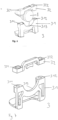
- Figure 1 shows an adapter 1 consisting of two components 11, 12.
- the first component 11 is a bottom bracket and is essentially U-shaped and has an area 113 which serves to support and grip a section of the end button 5.
- the first component has an area which serves to support the bottom of the instrument.
- the first component 11 has on its outside receptacles 111, 112 in the form of external threads for fastening means.
- the second component 12 is designed in the form of a saddle bracket 123 and serves to support the top or the ceiling of the instrument.
- the second component 12 has a rounded E-shape 123, which simplifies assembly on the tailpiece. On the one hand, this serves to support the instrument, and on the other hand, the legs of the E-shape grip the tailpiece.
- the rounded E-shape 123 grips the tailpiece at its lower area at three points (bottom and on both sides).
- the second component 12 can also be designed as a bow.
- the rounded outer legs of the E-shape or bow are bent and rounded towards the axis of symmetry.
- the middle leg of the "E" is shortened.
- the free end sections of at least the outer legs are bent out of one plane so that they overlap an edge bar that protrudes over the top of the string instrument and the adapter 1 can be securely fixed in place.
- the shape is adapted to enable the second component 12 to be "threaded" around the tailpiece as easily as possible.
- the second component 12 also has receptacles 121, 122 on its outer sides for fastening means in the form of external threads. Both components 11, 12 are arranged relative to one another by suitable connecting means 13, in this case two opposing twist lock sleeves with internal threads, and are connected to one another as a result of the threaded connection.
- suitable connecting means 13 in this case two opposing twist lock sleeves with internal threads, and are connected to one another as a result of the threaded connection.
- the tailpiece button 8 rests on the U-shaped area 113 and is engaged with the second component 12 as a result of the connection.
- the second component 12 rests on the top or the ceiling of the instrument and creates a stable connection between the components and the instrument.
- the first component 11 rests on the bottom of the instrument.
- the support is preferably on the lower saddle and in the region of the lower saddle/the upper edge of the instrument in the ceiling area above the end block.
- Figure 2 shows the adapter 1 described above from the opposite side, ie with a view of the instrument, of which only the tailpiece button 8 is shown.
- the adapter 2 has an upper section 3 in the form of a saddle bracket, a middle section 22 and a lower section 21 in the form of a base bracket, the middle section 22 having a recess 223 for the tailpiece button 8 of the string instrument.
- the recess in the middle section 22 is essentially U-shaped to accommodate the tailpiece button 8. This allows the adapter 2 to be attached flush to the frame of the instrument and the end button 8 is received in the area 223 without contact.
- the upper section 23 is attached to the middle section 22 and has the rounded E-shape already described above, which simplifies installation on the tailpiece.
- the lower section 21, or the base bracket is essentially L-shaped and has a tab 211 for attaching a support element to the user's chest/collarbone.
- the horizontal leg of the "L" is suitable for resting on the base of the instrument.
- the adapter 2 also has an element 24 for adjusting and locking the angular position of the middle part 22 to the tab 211.
- the middle section 22 has receiving elements in the form of sleeves 224, 225 for receiving a chin rest.
- the adapter 2 has receptacles 221, 222 for connecting means, e.g. screws, on its outer sides.
- the mutual alignment and locking of the sections of the adapter 2 can be carried out, for example, by means of a screw connection on the upper section 23, whereby the lower 21, middle 22 and upper section 23 are correctly positioned relative to one another and with regard to the arrangement on the instrument.
- Figure 4 shows the previously described adapter 2 of the Figure 3 from the view towards the instrument, of which only its end button 8 is shown.
- Figure 5 shows the adapter 2 attached to a violin, in which the tailpiece button 8 is received in the recess 223 of the middle section 22 without contact.
- the lower section 21 is placed on the bottom or lower frame of the violin and the tailpiece button 8 is arranged in the recess 223 without contact.
- the sections of the adapter 2 are arranged relative to one another, with the lower section 21 being fastened to the bottom or lower frame and the upper section in the form of the fastening element 23 being fastened to the upper frame of the violin. This is preferably done in the region of the lower saddle. This creates a stable connection between the adapter 2 and the instrument.
- the rounded E-shape of the fastening element 23 encloses the tailpiece ropes.
- the fastening is therefore carried out on the top and bottom of the instrument, whereby the tailpiece button 8 is not touched. Due to the tension, or the distance between the fastening element 23 and the lower section 21 of the adapter 2, or due to the positive By attaching the adapter 2 to the violin body, the adapter 2 is securely attached to the sound body of the string instrument.
- the adapter 3 consists of a first lower component 31 in the form of a bottom bracket and a second upper component 31.
- the first component 31 is essentially in the form of a bracket and has a U-shaped receiving area 313 which serves to receive a first section of the tailpiece button 8.
- the bracket shape of the first component 31 serves to rest on the bottom of the instrument.
- the first component 31 has on its outer sides receptacles 311, 312 for connecting means (not shown).
- the second component 32 has an area 323 for receiving a further second section of the end button 8 (opposite the first section).
- the second component 32 also has on its outer sides receptacles 321, 322 for fastening means.
- the two components are arranged relative to one another and the end button 8 is positively engaged between the two support areas 313, 323 of the two components. This creates a stable connection between the adapter 3 and the instrument. It is attached to the tailpiece button 8 and the bottom of the instrument
- Figure 7 shows the adapter 3 according to Figure 6 without showing the end button.
- the receiving area 323 of the end button of the upper second component 32 is clearly visible.
- Figure 8 represents an adapter.
- the adapter 4 consists of two components 41 and 42.
- the first component 41 is essentially U-shaped and has an area 413 which serves to support and grip a section of the end button 8 (not shown).
- the first component 41 has on its outer sides receptacles 411, 412 in the form of external threads for fastening means.
- the second component 42 is designed in the form of a saddle bracket 423 with rim feet and serves to support the top or the top of the instrument.
- the second component 42 also has on its outer sides receptacles 421, 422 for fastening means in the form of external threads.
- Both components 41, 42 are arranged relative to one another by suitable connecting means 43, in this case two opposing twist lock sleeves with internal threads, and are connected to one another as a result of the threaded connection.
- the tailpiece button 8 rests on the U-shaped area 413 and is engaged as a result of the connection with the second component 42.
- the second component 42 rests on the top or the top of the instrument and creates a stable connection between the components and the instrument.
- the support is preferably on the lower saddle and in the region of the lower saddle/the upper edge of the instrument in the top area above the end block.
- Figures 9A and 9B show a variant of the adapter 4 from the perspective of the instrument ( Figure 9A ) and with a view of the instrument ( Figure 9B ).
- the first component 51 of the adapter has receptacles 511, 512 for fastening means on its outer sides.
- the second component 52 is designed in the form of a closed undersaddle bracket 523 and is used to rest on the upper side or on the undersaddle of the instrument.
- the second component 52 also has receptacles 521, 522 for connecting means (not shown) on its outer sides. Both components 51, 52 are connected to one another by suitable connecting means (not shown).
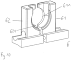
- Figure 10 shows a further adapter 6 with two components 61, 62 in the form of two uniform clamping parts, each of which has an area for supporting the tailpiece button 8 (not shown). The areas are adapted to the shape of the tailpiece button 8.
- Both components 61, 62 are pulled together from two sides around the tailpiece button 8 of the string instrument and then locked. The pulling together and locking can be done, for example, by means of a screw connection or a wedge connection (neither shown). In the latter case, the two components 61, 62 can be correctly positioned relative to one another by tightening the wedge. In this embodiment, the fastening is also only done on the tailpiece button 8 without touching the rest of the instrument body.
- FIG 11 shows a further variant of the adapter.
- the first component 71 is essentially U-shaped and an area 713 serves to accommodate a first section of the tailpiece button 8.
- the first component 71 has receptacles 711, 712 for connecting means (not shown) on its outer sides.
- the second component 72 has an area 723 for receiving a further second section of the end button 8 (opposite the first section) and has two recesses 724 for tailpiece cables.
- the second component 72 also has receptacles 721, 722 for fastening means on its outer sides.
- the two components are arranged relative to one another and the end button 8 is positively engaged between the two support areas 713, 723 of the two components.
- the attachment takes place solely on the tailpiece button 8 without touching the rest of the violin body. This has the advantage that the connection has no negative effect on the sound body of the instrument and the sound and volume of the instrument are not affected.
- Figure 12 shows the previously described adapter 7 from the opposite view, ie looking towards the instrument (represented by end button 8).
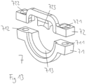
- Figure 13 shows a variant of the adapter 7 in a slimmer version without showing the end button
- the fastening element 23; 523 can be designed as a bow overall.
- the rounded outer legs of the E-shape or the bow are bent and rounded towards the axis of symmetry.
- the middle leg of the "E" is shortened.
- the free end sections of at least the outer legs are bent out of one plane so that they overlap an edge bar that protrudes over the top of the string instrument and the adapter 2 or 5 can be securely fixed in place.
- the shape is adapted to enable the fastening element 23; 523 to be "threaded" around the tailpiece as easily as possible. In the case of the closed bow shape 523, the tailpiece ropes are passed under the bow shape.
- Figure 15 shows a schematic representation of the basic structure, or the connection of a string instrument with an adapter 1 to 7 according to the invention (in this case adapter 2) such as in the Figures 1 to 14 which is connected to a support device 10 via a carrier module 9.
- the multi-part carrier module 9 is height-adjustable and can thus be adjusted to the length of the neck of the respective user of the instrument.
- the support device 10 has a collarbone support 102 and a chest support 103 in its lower area and a chin support 101 in its upper area.
- the above-mentioned supports have padding to protect the skin and muscles of the user.
Landscapes
- Physics & Mathematics (AREA)
- Engineering & Computer Science (AREA)
- Acoustics & Sound (AREA)
- Multimedia (AREA)
- Stringed Musical Instruments (AREA)
- Auxiliary Devices For Music (AREA)
Description
- Die vorliegende Erfindung betrifft einen Adapter zum Anbringen einer Stützvorrichtung für ein Streichinstrument, insbesondere für eine Geige oder eine Bratsche, umfassend: eine erste Komponente, eine zweite Komponente und eine Verbindungsvorrichtung.
- Weiterhin umfasst die Erfindung ein Trägermodul, das mit einem Adapter verbunden ist sowie eine Stützvorrichtung für ein Streichinstrument, umfassend mindestens ein Abstützelement zum Anlegen an den Hals-/Kinn-/Schulterbereich eines Benutzers, und einen mit dem Abstützelement verbundenen Adapter.
- Adapter für Stützvorrichtungen für Streichinstrumente, insbesondere für Geigen, Violinen und ähnliche Instrumente sind bekannt und dienen der mechanischen Verbindung zwischen Stütze und Instrument. Das Element der Stützvorrichtung als Ganzes dient der freihändigen Lagerung des Instruments am Körper des Benutzers während des Spielens, zu dem Zweck, dass die musizierende Person beide Hände zum Spielen des Instruments zur Verfügung hat. Die Stützvorrichtung weist dabei in der Regel Auflagen zum Abstützen im Bereich des Kinns, der Schulter und der Brust auf. Der Kinnbereich ist in der Regel auf der Oberseite des Instruments angeordnet, der Schulter- / Brustbereich ist zumeist an der Unterseite des Instruments angeordnet. Das Instrument wird durch eine Anordnung zwischen Kinn und Schulter, bzw. Brust des Benutzers eingeklemmt.
- Die
DE 197 17 338 A1 beschreibt ein Stützgerät für geigenähnliche Musikinstrumente, bei dem ein Kinnhalter, eine Schlüsselbeinstütze, eine Schulterstütze und eine Bruststütze an einem Träger angeordnet sind und der Träger am Instrument befestigt ist. - Problematisch hat sich hierbei erwiesen, dass die vorgenannte Anordnung des Instruments an den entsprechenden Berührungspunkten des menschlichen Körper körperliche Beeinträchtigungen in den genannten Bereichen nach sich ziehen kann. Ursache hierfür ist, dass die herkömmlichen Stützvorrichtungen nicht optimal an die individuellen ergonomisch-anatomischen Bedürfnisse angepasst werden können, obwohl dies erforderlich ist, da die körperlichen Gegebenheiten in den genannten Bereichen je nach Benutzer unterschiedlich sind. Ebenfalls wurde hierbei bislang auch nicht auf geschlechtsspezifische Unterschiede beim Körperbau Rücksicht genommen. Dies lag vor allem daran, dass bisher primär die bestmögliche Anpassung des jeweiligen Instruments an den Benutzer im Vordergrund stand und dessen körperliche Begebenheiten hierbei nur sekundär Berücksichtigung fanden. Infolge einer unzureichenden Anpassung des Instruments an den Benutzer ist auch eine Benutzung des Instruments erschwert und die erwünschte Musikqualität wird gemindert. Die vorliegende Erfindung stellt aus diesem Grund die Anpassung der individuellen körperlichen Begebenheiten an das jeweilige Instrument in den Vordergrund
-
DE 10 2008 016 521 A1 offenbart einen Kinnhalter für Streichinstrumente mit mit zwei am Kinnhalterteller befestigbaren Stegen, die von der der Decke des Streichinstruments zugewandten Grundfläche des Kinnhaltertellers abgewinkelt sind und durch einen Verbindungsblock miteinander verbindbar sind. Ein U-förmiger Bügel ist so angeordnet, dass dieser den Endknopf zur Befestigung der Einhängesaiten des Saitenhalters an der dem Kinnhalterteller zugewandten Seite umgreift bzw. hintergreift. - Von daher liegt der Erfindung die Aufgabe zugrunde, einen Adapter für eine Stützvorrichtung an einem Streichinstrument bereitzustellen, der eine stabile und flexible Verbindung zwischen Stützvorrichtung und Instrument im Hinblick auf statische, musikalische, physiologische und medizinische Anforderungen herstellt.
- Die Aufgabe wird durch einen erfindungsgemäßen Adapter zum Anbringen einer Stützvorrichtung für ein Streichinstrument gemäß Anspruch 1 gelöst.
-
- Figur 1
- Adapter mit einer ersten unteren Komponente in Form eines Bodenbügels und einer zweiten oberen Komponente in Form eines Untersattelbügels. Der Untersattelbügel hat eine gerundete E-Form, wodurch der untere und die seitlichen unteren Bereiche des Saitenhalters des Instruments beim Anbringen des Befestigungselements am Streichinstrument in Umgriff genommen werden. Der Untersattelbügel und der Bodenbügel weist Schraubzonen auf, die mit zwei Drehverschlusshülsen verbunden werden. Ansicht vom Instrument her;
- Figur 2
- Adapter entsprechend
Figur 1 ; Ansicht zum Instrument hin; - Figur 3
- Ausführung eines erfindungsgemäßen Adapters mit einem oberen (Untersattelbügel), mittleren (Mittelteil) und unteren Abschnitt (Bodenbügel). Das Mittelteil weist eine Aussparung zur Aufnahme des Saitenknopfes auf. Der Bodenbügel ist zur Auflage am Boden des Streichinstruments ausgebildet und hat eine Lasche zum Brustteil;
- Figur 4
- Erfindungsgemäßer Adapter entsprechend
Figur 3 ; Ansicht zum Instrument hin (angedeutet durch Saitenhalter); - Figur 5
- Darstellung eines montierten Adapters gemäß
Figuren 3 und 4 . Draufsicht auf die Oberseite der Geige. Der Saitenhalter liegt dabei berührungsfrei in der Aussparung des mittleren Abschnitts. Die Saitenhalterseile werden von der oberen Komponente in Umgriff genommen; - Figur 6
- Erfindungsgemäßer Adapter, wobei eine Komponente einen Bügel und ein U-Profil zur Auflage auf dem Saitenhalterknopf von unten aufweist und der Bügel zur Auflage am Boden des Instruments geeignet ist und die andere Komponente in Form eines Bügels zur Auflage an der Oberseite des Instruments ist. Beide Komponenten weisen Aufnahmen und Durchgänge für entsprechende Verbindungselemente auf. Die Zargen der Geige werden durch die beiden Komponenten von oben und unten in Eingriff genommen;
- Figur 7
- Adapter entsprechend
Figur 6 ; Darstellung ohne Endknopf; - Figur 8
- Adapter, wobei eine Komponente im Wesentlichen in U-Form ist und ein U-Profil zur Auflage des Saitenhalterknopfs von unten aufweist und die andere Komponente in Form eines Bügels mit Zargenfüßchen zur Auflage an der Oberseite des Instruments ist. Beide Komponenten weisen Aufnahmen und Durchgänge für entsprechende Verbindungselemente auf;
- Figuren 9A, 9B
- Variante des Adapters gemäß
Figur 8 in zwei Ansichten; - Figur 10
- Adapter, wobei der Saitenhalterknopf von beiden Komponenten umfasst wird;
- Figur 11
- Adapter, wobei der Saitenhalterknopf auf einem Bereich einer Komponente in U- Form und durch Auflage auf einem Bereich der anderen Komponente aufliegt. Beide Komponenten weisen Aufnahmen und Durchgänge für entsprechende Verbindungselemente auf; Ansicht vom Instrument her;
- Figur 12
- Adapter entsprechend
Figur 11 ; Ansicht zum Instrument hin; - Figur 13
- Variante des Adapters gemäß
Figuren 11 und12 in schlankerer Form; - Figur 14
- Oberer Abschnitt des Adapters in Form eines Befestigungselements zur Befestigung am Untersattel, das eine gerundete E-Form aufweist, wodurch der untere und die seitlichen unteren Bereiche des Saitenhalters des Instruments beim Anbringen des Befestigungselements am Streichinstrument in Umgriff genommen werden (obere Zeichnung). Oberer Abschnitt des Adapters in Form eines Befestigungselements in geschlossener Form, welche unter den Saitenhalterseilen durchgeführt wird (untere Zeichnung);
- Figur 15
- Gesamtdarstellung eines erfindungsgemäßen Adapters mit einem höhenverstellbaren Trägermodul zur Verbindung mit einer Stützvorrichtung, welche mit Auflagen für Kinn, Brust und Schlüsselbein versehen ist.
-
Figur 1 zeigt einen Adapter 1, der aus zwei Komponenten 11, 12 besteht. Die erste Komponente 11 ist ein Bodenbügel und ist im Wesentlichen U-förmig ausgeprägt und hat einen Bereich 113, der der Auflage und dem Umgreifen eines Abschnitts des Endknopfes 5 dient. Daneben hat die erste Komponente einen Bereich, der der Auflage am Boden des Instruments dient. Die erste Komponente 11 weist an ihren Außenseiten Aufnahmen 111, 112 in Form von Außengewinden für Befestigungsmittel auf. Die zweite Komponente 12 ist in Form eines Untersattelbügels 123 ausgebildet und dient der Auflage an der Oberseite, bzw. der Decke des Instruments. Die zweite Komponente 12 weist dabei eine gerundete E-Form 123 auf, wodurch eine vereinfachte Montage am Saitenhalter bezweckt wird. Diese dient zum einen der Auflage auf dem Instrument, zum anderen umgreifen die Schenkel der E-Form den Saitenhalter. - Durch die gerundete E-Form 123 wird der Saitenhalter an seinem unteren Bereich an drei Punkten (unten und an beiden Seiten) in Umgriff genommen. Die zweite Komponente 12 kann auch insgesamt bügelartig ausgebildet sein. Die abgerundeten äußeren Schenkel der E-Form bzw. des Bügels sind zur Symmetrieachse hin gebogen und abgerundet. Der mittlere Schenkel des "E" ist verkürzt. Außerdem sind die freien Endabschnitte zumindest der äußeren Schenkel aus einer Ebene herausgebogen, sodass sie einen über die Oberseite des Streichinstruments hinausragenden Randsteg übergreifen und so der Adapter 1 sicher fixiert werden kann. Die Form ist dazu angepasst, ein möglichst leichtes "Einfädeln" der zweiten Komponente 12 um den Saitenhalter herum zu ermöglichen.
- Auch die zweite Komponente 12 weist an ihren Außenseiten Aufnahmen 121, 122 für Befestigungsmittel in Form von Außengewinden auf. Beide Komponenten 11, 12 werden durch geeignete Verbindungsmittel 13 , vorliegend zwei gegenläufige Drehverschlusshülsen mit Innengewinden zueinander angeordnet und infolge der Gewindeverbindung miteinander verbunden. Dabei liegt der Saitenhalterknopf 8 auf dem U-förmigen Bereich 113 auf und wird infolge der Verbindung mit der zweiten Komponente 12 in Eingriff genommen. Die zweite Komponente 12 liegt auf der Oberseite bzw. der Decke des Instruments auf und schafft eine stabile Verbindung der Komponenten mit dem Instrument. Die erste Komponente 11 liegt am Boden des Instruments an. Durch die Lagerung auf der Oberseite erfolgt die Auflage vorzugsweise auf dem unteren Sattel und in der Region des unteren Sattels/ des oberen Rands des Instruments im Deckenbereich über dem Endblock. Durch die Lagerung an der Ober-, bzw. Unterseite des Instruments wird eine Verdrehung, bzw. Drehbewegung des Adapters 1 um den Endknopf 8 unterbunden.
-
Figur 2 zeigt den oben beschriebenen Adapter 1 von der entgegengesetzten Seite, d.h. mit Sicht auf das Instrument, von dem lediglich der Saitenhalterknopf 8 dargestellt ist. - Aus
Figur 3 wird eine weitere erfindungsgemäße Ausführung des Adapters ersichtlich. Der Adapter 2 weist einen oberen Abschnitt 3 in Form eines Untersattelbügels, einen mittleren 22 und einen unteren Abschnitt 21 in Form eines Bodenbügels auf, wobei der mittlere Abschnitt 22 eine Aussparung 223 für den Saitenhalterknopf 8 des Streichinstruments aufweist. Die Aussparung des mittleren Abschnitts 22 ist im Wesentlichen in U-Form zur Aufnahme des Saitenhalterknopfs 8 ausgebildet. Dadurch kann der Adapter 2 bündig an der Zarge des Instruments angebracht werden und der Endknopf 8 wird berührungsfrei in dem Bereich 223 aufgenommen. Der obere Abschnitt 23 ist am mittleren Abschnitt 22 befestigt und weist dabei die bereits oben beschriebene gerundete E-Form auf, wodurch eine vereinfachte Montage am Saitenhalter bezweckt wird. Der untere Abschnitt 21, bzw. der Bodenbügel ist im Wesentlichen L-förmig ausgebildet und hat eine Lasche 211 zur Befestigung eines Stützenelements zum Brust/Schlüsselbein des Benutzers hin. Der horizontale Schenkel des "L" ist zur Auflage an dem Boden des Instruments geeignet. Der Adapter 2 hat außerdem ein Element 24 zur Einstellung und Arretierung der Winkelstellung des Mittelteils 22 zur Lasche 211. Der mittlere Abschnitt 22 weist Aufnahmeelemente in Form von Hülsen 224, 225 zur Aufnahme eines Kinnhalters auf. - Der Adapter 2 weist an seinen Außenseiten Aufnahmen 221, 222 für Verbindungsmittel, z.B. Schrauben, auf. Die gegenseitige Ausrichtung und die Arretierung der Abschnitte des Adapters 2 können beispielsweise mittels einer Schraubverbindung am oberen Abschnitt 23 erfolgen, wodurch der untere 21, mittlere 22 und obere Abschnitt 23 korrekt zueinander und im Hinblick auf die Anordnung am Instrument positioniert werden.
-
Figur 4 zeigt den vorher beschriebenen Adapter 2 derFigur 3 aus der Sicht zum Instrument hin, von dem lediglich dessen Endknopf 8 dargestellt ist. -
Figur 5 zeigt den an einer Geige angebrachten Adapter 2, bei dem der Saitenhalterknopf 8 in der Aussparung 223 des mittleren Abschnitts 22 berührungsfrei aufgenommen wird. Für die Montage des Adapters 2 wird der untere Abschnitt 21 an den Boden, bzw. an der unteren Zarge der Geige angelegt und der Saitenhalteknopf 8 in der Aussparung 223 berührungsfrei angeordnet. Unter Verwendung der Verbindungsmittel werden die Abschnitte des Adapters 2 zueinander angeordnet, wobei der untere Abschnitt 21 am Boden, bzw. der unteren Zarge und der obere Abschnitt in Form des Befestigungselements 23 an der oberen Zarge der Geige befestigt wird. Dies erfolgt vorzugsweise in der Region des Untersattels. Dadurch wird eine stabile Verbindung des Adapters 2 mit dem Instrument erzielt. Durch die gerundete E-Form des Befestigungselements 23 werden die Saitenhalterseile umschlossen. - Die Befestigung erfolgt von daher an der Ober- und Unterseite des Instruments, wobei der Saitenhalterknopf 8 nicht berührt wird. Durch die Verspannung, bzw. dem Abstand zwischen dem Befestigungselement 23 und dem unteren Abschnitt 21 des Adapters 2, bzw. durch das formschlüssige Anbringen des Adapters 2 am Geigenkörper ist der Adapter 2 sicher am Resonanzkörper des Streichinstruments befestigt.
- Aus
Figur 6 wird eine zweite Ausführung des erfindungsgemäßen Adapters erkennbar. Der Adapter 3 besteht aus einer ersten unteren Komponente 31 in Form eines Bodenbügels und einer zweiten oberen Komponente 31. Die erste Komponente 31 ist hierbei im Wesentlichen in Form eines Bügels ausgeprägt und hat einen U-förmigen Aufnahmebereich 313, der der Aufnahme eines ersten Abschnitts des Saitenhalterknopfs 8 dient. Die Bügelform der ersten Komponente 31 dient der Auflage am Boden des Instruments. Die erste Komponente 31 weist an ihren Außenseiten Aufnahmen 311, 312 für Verbindungsmittel (nicht dargestellt) auf. Die zweite Komponente 32 weist einen Bereich 323 zur Aufnahme eines weiteren (dem ersten Abschnitt gegenüber liegenden) zweiten Abschnitts des Endknopfes 8 auf. Auch die zweite Komponente 32 weist an ihren Außenseiten Aufnahmen 321, 322 für Befestigungsmittel auf. Unter Verwendung der Verbindungsmittel werden die beiden Komponenten zueinander angeordnet und der Endknopf 8 zwischen den beiden Auflagebereichen 313, 323 der beiden Komponenten formschlüssig in Eingriff genommen. Dadurch wird eine stabile Verbindung des Adapters 3 und dem Instrument erzielt. Die Befestigung erfolgt am Saitenhalterknopf 8 und dem Boden des Instruments -
Figur 7 zeigt den Adapter 3 gemäßFigur 6 ohne Darstellung des Endknopfes. Der Aufnahmebereich 323 des Endknopfes der oberen zweiten Komponente 32 ist deutlich erkennbar. -
Figur 8 stellt einen Adapter dar. Der Adapter 4 besteht aus zwei Komponenten 41 und 42. Die erste Komponente 41 ist im Wesentlichen U-förmig ausgeprägt und hat einen Bereich 413, der der Auflage und dem Umgreifen eines Abschnitts des Endknopfes 8 (nicht dargestellt) dient. Die erste Komponente 41 weist an ihren Außenseiten Aufnahmen 411, 412 in Form von Außengewinden für Befestigungsmittel auf. Die zweite Komponente 42 ist in Form eines Untersattelbügels 423 mit Zargenfüßchen ausgebildet und dient der Auflage an der Oberseite, bzw. der Decke des Instruments. Auch die zweite Komponente 42 weist an ihren Außenseiten Aufnahmen 421, 422 für Befestigungsmittel in Form von Außengewinden auf. Beide Komponenten 41, 42 werden durch geeignete Verbindungsmittel 43, vorliegend zwei gegenläufige Drehverschlusshülsen mit Innengewinden, zueinander angeordnet und infolge der Gewindeverbindung miteinander verbunden. Dabei liegt der Saitenhalterknopf 8 auf dem U-förmigen Bereich 413 auf und wird infolge der Verbindung mit der zweiten Komponente 42 in Eingriff genommen. Die zweite Komponente 42 liegt auf der Oberseite bzw. der Decke des Instruments auf und schafft eine stabile Verbindung der Komponenten mit dem Instrument. Durch die Lagerung auf der Oberseite erfolgt die Auflage vorzugsweise auf dem unteren Sattel und in der Region des unteren Sattels/ des oberen Rands des Instruments im Deckenbereich über dem Endblock. Durch die Lagerung an der Ober-, bzw. Unterseite des Instruments wird eine Verdrehung, bzw. Drehbewegung des Adapters 4 um den Endknopf 8 unterbunden. -
Figuren 9A und 9B zeigen eine Variante des Adapters 4 aus Sicht des Instruments (Figur 9A ) und mit Sicht auf das Instrument (Figur 9B ). Die erste Komponente 51 des Adapters weist hierbei an ihren Außenseiten Aufnahmen 511, 512 für Befestigungsmittel auf. Die zweite Komponente 52 ist in Form eines Untersattelbügels 523 in geschlossener Form ausgebildet und dient der Auflage an der Oberseite, bzw. am Untersattel des Instruments. Auch die zweite Komponente 52 weist an ihren Außenseiten Aufnahmen 521, 522 für Verbindungsmittel (nicht dargestellt) auf. Beide Komponenten 51, 52 werden durch geeignete Verbindungsmittel (nicht dargestellt) miteinander verbunden. -
Figur 10 zeigt einen weiteren Adapter 6 mit zwei Komponenten 61, 62 in Form von zwei gleichförmigen Klemmteilen, die jeweils einen Bereich zur Auflage 611, 621 des Saitenhalterknopfes 8 (nicht dargestellt) aufweisen. Die Bereiche sind an die Form des Saitenhalterknopfes 8 angepasst. Beide Komponenten 61, 62 werden um den Saitenhalterknopf 8 des Streichinstruments von zwei Seiten zusammengezogen und im Anschluss arretiert. Das Zusammenziehen und die Arretierung kann beispielsweise mittels einer Schraubverbindung oder einer Keilverbindung (beides nicht dargestellt) erfolgen. Im letztgenannten Fall können durch ein Anziehen im Keil die beiden Komponenten 61, 62 korrekt zueinander positioniert werden. Die Befestigung erfolgt auch in diesem Ausführungsbeispiel nur am Saitenhalterknopf 8 ohne den restlichen Instrumentenkorpus zu berühren. - Dies hat den Vorteil, dass die Verbindung keinerlei negative Auswirkung auf den Klangkörper des Instruments hat und der Klang und die Lautstärke nicht beeinträchtigt werden.
Figur 11 zeigt eine weitere Variante des Adapters. Die erste Komponente 71 ist hierbei im Wesentlichen in U-Form ausgeprägt und ein Bereich 713 dient der Aufnahme eines ersten Abschnitts des Saitenhalterknopfs 8. Die erste Komponente 71 weist an ihren Außenseiten Aufnahmen 711, 712 für Verbindungsmittel (nicht dargestellt) auf. Die zweite Komponente 72 weist einen Bereich 723 zur Aufnahme eines weiteren (dem ersten Abschnitt gegenüber liegenden) zweiten Abschnitts des Endknopfes 8 auf und hat zwei Aussparungen 724 für Saitenhalterseile. Auch die zweite Komponente 72 weist an ihren Außenseiten Aufnahmen 721, 722 für Befestigungsmittel auf. Unter Verwendung der Verbindungsmittel werden die beiden Komponenten zueinander angeordnet und der Endknopf 8 zwischen den beiden Auflagebereichen 713, 723 der beiden Komponenten formschlüssig in Eingriff genommen. Dadurch wird eine stabile Verbindung des Adapters 7 und dem Instrument erzielt. Die Befestigung erfolgt allein am Saitenhalterknopf 8 ohne den restlichen Geigenkorpus zu berühren. Dies hat den Vorteil, dass die Verbindung keinerlei negative Auswirkung auf den Klangkörper des Instruments hat und der Klang und die Lautstärke des Instruments nicht beeinträchtigt werden. -
Figur 12 zeigt den vorher beschriebenen Adapter 7 aus der entgegengesetzten Ansicht, d.h. mit Blick zum Instrument hin (dargestellt durch Endknopf 8). -
Figur 13 zeigt eine Variante des Adapters 7 in einer schlankeren Version ohne Darstellung des Endknopfes, -
Figur 14 zeigt den oberen Abschnitt in Form eines Befestigungselements in zwei Ausführungsformen Als anschauliches, aber nicht abschließendes Beispiel hierfür, werden die Komponenten 23 des Adapters 2 und 523 des Adapters 5 verwendet. Durch die Aufnahmen 231 und 232; 521 und 522 können Verbindungsmittel aufgenommen werden. Das Befestigungselement 23 weist beispielsweise eine gerundete E-Form (oben) oder eine Bügelform 523 (unten) auf, wodurch eine vereinfachte Montage am Saitenhalter bezweckt wird. Zum einen dient das Befestigungselement 23 der Auflage auf dem Instrument, zum anderen umgreifen die Schenkel der E-Form den Saitenhalter. Durch die gerundete E-Form wird der Saitenhalter an seinem untern Bereich an drei Punkten (unten und an beiden Seiten) in Umgriff genommen. Das Befestigungselement 23; 523 kann insgesamt bügelartig ausgebildet sein. Die abgerundeten äußeren Schenkel der E-Form bzw. des Bügels sind zur Symmetrieachse hin gebogen und abgerundet. Der mittlere Schenkel des "E" ist verkürzt. Außerdem sind die freien Endabschnitte zumindest der äußeren Schenkel aus einer Ebene herausgebogen, sodass sie einen über die Oberseite des Streichinstruments hinausragenden Randsteg übergreifen und so der Adapter 2, bzw. 5 sicher fixiert werden kann. Die Form ist dazu angepasst, ein möglichst leichtes "Einfädeln" des Befestigungselements 23; 523 um den Saitenhalter herum zu ermöglichen. Im Falle der geschlossenen Bügelform 523 werden die Saitenhalterseile unter der Bügelform durchgeführt. -
Figur 15 zeigt eine schematische Darstellung des prinzipiellen Aufbaus, bzw. der Verbindung von einem Streichinstrument mit einem erfindungsgemäßen Adapter 1 bis 7 (vorliegend Adapter 2) wie beispielweise wie in denFiguren 1 bis 14 beschrieben, der über ein Trägermodul 9 mit einer Stützvorrichtung 10 verbunden wird. Das mehrteilige Trägermodul 9 ist höhenverstellbar und ist auf diese Weise auf die Länge des Halses des jeweiligen Benutzers des Instruments einstellbar. Die Stützvorrichtung 10 weist in ihrem unteren Bereich eine Schlüsselbeinauflage 102 und eine Brustauflage 103 sowie in ihrem oberen Bereich eine Stütze für das Kinn 101 auf. Die genannten Auflagen, bzw. Stützen weisen Polsterungen auf, um die Haut und Muskulatur des Benutzers zu schützen.
Claims (8)
- Adapter (1; 2; 3; 4; 5; 6; 7;) zum Anbringen einer Stützvorrichtung (10) für ein Streichinstrument, insbesondere für eine Geige oder eine Bratsche, umfassend:eine erste Komponente (11; 21; 31; 41; 51; 61; 71),eine zweite Komponente (12; 23; 32; 42; 52; 62; 72),eine Anschlussvorrichtung für die Stützvorrichtung (10); undeine Verbindungsvorrichtung, wobeidie erste Komponente (11; 21; 31; 41; 51; 61; 71) und/oder die zweite Komponente (12; 23; 32; 42; 52; 62; 72) einen mittleren Abschnitt mit einer Aussparung (223) für den Saitenhalterknopf (8) des Streichinstruments aufweist, dadurch gekennzeichnet, dassdie erste Komponente (11; 21; 31; 41; 51; 61: 71) und die zweite Komponente (12; 23; 32; 42; 52; 62; 72) derart angeordnet und durch die Verbindungsvorrichtung verbunden sind, dass der Saitenhalterknopf infolge der Verbindung der ersten Komponente (11; 21; 31; 41; 51; 61: 71) mit der zweiten Komponente (12; 23; 32; 42; 52; 62; 72) berührungsfrei in der Aussparung (223) aufgenommen wird, und dass die erste Komponente (11; 21; 31; 41; 51; 61; 71) und die zweite Komponente (12; 23; 32; 42; 52; 62; 72) zur Anlage am Boden und an der Decke des Streichinstruments ausgebildet ist.
- Adapter (1; 2; 3; 4; 5; 6; 7) nach Anspruch 1,
dadurch gekennzeichnet, dass
die Verbindungsvorrichtung eine im Wesentlichen starre Verbindung zwischen der ersten Komponente (11; 21; 31; 41; 51; 61: 71) und der zweiten Komponente (12; 23; 32; 42; 52; 62; 72) herstellt. - Adapter (1; 2; 3; 4; 5; 6; 7) nach einem der vorhergehenden Ansprüche, dadurch gekennzeichnet, dass die erste Komponente (11; 21; 31; 41; 51; 61; 71) wenigstens einen ersten Befestigungsabschnitt (111; 211; 311; 411; 511; 711) zur Verbindung mit der Verbindungsvorrichtung und/oder einen zweiten Befestigungsabschnitt (112; 212; 312; 412; 512; 712) zur Verbindung mit der Verbindungsvorrichtung aufweist.
- Adapter (2; 3; 5; 6; 7) nach Anspruch 3, dadurch gekennzeichnet, dass der erste Befestigungsabschnitt (311; 511; 711) und/oder der zweite Befestigungsabschnitt (312; 512; 712) jeweils wenigstens einen Durchgang mit einem Innengewinde zur Aufnahme der Verbindungsvorrichtung aufweisen.
- Adapter (1; 2; 4; 5) nach einem der vorhergehenden Ansprüche, dadurch gekennzeichnet, dass die zweite Komponente (12; 23; 32; 52) bügelartig zur Auflage auf der Decke oder dem Boden des Streichinstruments ausgebildet ist.
- Adapter (1; 2; 3; 4; 5; 6; 7) nach einem der vorhergehenden Ansprüche, dadurch gekennzeichnet, dass die zweite Komponente (12; 23; 32; 42; 52; 72) einen dritten Befestigungsabschnitt (121; 231; 321; 421; 521; 721) zur Verbindung mit der Verbindungsvorrichtung und/oder einen vierten Befestigungsabschnitt (122; 232; 322; 422; 522; 722) zur Verbindung mit der Verbindungsvorrichtung aufweist.
- Adapter (2; 3; 5; 6; 7) nach Anspruch 6, dadurch gekennzeichnet, dass der dritte Befestigungsabschnitt (121; 231; 321; 521; 721) und der vierte Befestigungsabschnitt (122; 232; 322; 522; 722) jeweils wenigstens einen Durchgang mit einem Innengewinde zur Aufnahme der Verbindungsvorrichtung aufweisen.
- Stützvorrichtung (10) für ein Streichinstrument, umfassend mindestens ein Abstützelement zum Anlegen an den Hals-, Kinn-, und/oder Schulterbereich eines Benutzers, und einen mit dem Abstützelement verbundenen Adapter (1; 2; 3; 4; 5; 6; 7) nach einem der vorhergehenden Ansprüche.
Applications Claiming Priority (1)
| Application Number | Priority Date | Filing Date | Title |
|---|---|---|---|
| PCT/EP2016/062388 WO2017207047A1 (de) | 2016-06-01 | 2016-06-01 | Adapter für eine stützvorrichtung für ein streichinstrument |
Publications (3)
| Publication Number | Publication Date |
|---|---|
| EP3465674A1 EP3465674A1 (de) | 2019-04-10 |
| EP3465674B1 true EP3465674B1 (de) | 2024-10-09 |
| EP3465674C0 EP3465674C0 (de) | 2024-10-09 |
Family
ID=56409588
Family Applications (1)
| Application Number | Title | Priority Date | Filing Date |
|---|---|---|---|
| EP16738364.5A Active EP3465674B1 (de) | 2016-06-01 | 2016-06-01 | Adapter für eine stützvorrichtung für ein streichinstrument |
Country Status (7)
| Country | Link |
|---|---|
| US (1) | US10943569B2 (de) |
| EP (1) | EP3465674B1 (de) |
| JP (1) | JP6893977B2 (de) |
| KR (1) | KR102312492B1 (de) |
| CN (1) | CN109564752A (de) |
| CA (1) | CA3026137C (de) |
| WO (1) | WO2017207047A1 (de) |
Families Citing this family (1)
| Publication number | Priority date | Publication date | Assignee | Title |
|---|---|---|---|---|
| CN109564752A (zh) * | 2016-06-01 | 2019-04-02 | 伊莎贝尔·莫莉娜 | 用于弦乐器的支承装置的适配器 |
Citations (1)
| Publication number | Priority date | Publication date | Assignee | Title |
|---|---|---|---|---|
| DE102008016521A1 (de) * | 2008-03-31 | 2009-10-08 | Christian-Godehard Kirscht | Kinnhalter für Streichinstrumente |
Family Cites Families (32)
| Publication number | Priority date | Publication date | Assignee | Title |
|---|---|---|---|---|
| US217330A (en) * | 1879-07-08 | Improvement in insulating attachments for violins | ||
| US627692A (en) | 1898-08-06 | 1899-06-27 | George E Hoffmann | Violin-rest. |
| US664718A (en) | 1900-03-24 | 1900-12-25 | Charles W Brewster | Violin-support. |
| US1958451A (en) | 1933-01-20 | 1934-05-15 | Lester Lamkin W | Violin positioning attachment |
| US2061464A (en) * | 1933-02-11 | 1936-11-17 | Heimers Rudolf | Violin holder |
| DE604834C (de) | 1933-02-12 | 1934-10-29 | Rudolf Heimers | Geigenhalter |
| US2486646A (en) * | 1947-12-08 | 1949-11-01 | Halko William | Chin rest for violins |
| DE836591C (de) * | 1949-06-03 | 1952-04-15 | Franz Josef Rothaug | Geigenhaltestuetze |
| GB954359A (en) | 1959-06-04 | 1964-04-02 | Yehudi Menuhin | Improvements in or relating to violins |
| CH399885A (de) * | 1963-01-07 | 1965-09-30 | Meir Goldberger Erno | Vorrichtung zum Befestigen des Kinnhalters und des Saitenhalters an einer Violine |
| FR1571407A (de) | 1968-04-10 | 1969-06-20 | ||
| JPS5545432Y2 (de) * | 1976-12-18 | 1980-10-24 | ||
| DE3210739A1 (de) | 1981-04-25 | 1982-12-23 | Christian von Dipl.-Ing. 2000 Schenefeld Piechowski | Vorrichtung zur abstuetzung und halterung der geige oder bratsche am koerper waehrend des spielens |
| DE3216759C1 (de) * | 1982-05-05 | 1983-12-22 | Jaroslav 6000 Frankfurt Machala | Kinnstütze für ein Streichmusikinstrument |
| DE3920865A1 (de) | 1989-06-01 | 1991-02-21 | Klaus Winkler | Hohler saitenhalterknopf fuer die aufnahme eines mikrofons zur elektroakustischen verstaerkung von streichinstrumenten |
| FR2690268B1 (fr) | 1992-04-21 | 1997-07-04 | Roulet Paul Antoine | Support a l'epaule pour violon |
| DE4328066A1 (de) | 1993-08-20 | 1994-03-31 | Aleksej Slobodyrev | Einrichtung zur Befestigung des Kinnhalters einer Geige oder Bratsche |
| DE19645519A1 (de) | 1996-11-05 | 1997-07-03 | Aleksej Slobodyrev | Einrichtung zur Befestigung des Kinnhalters eines Streichinstruments |
| DE19717338A1 (de) * | 1997-04-24 | 1997-09-11 | Christian Gruen | Stützgerät für geigenähnliche Musikinstrumente |
| US6143964A (en) | 1999-09-09 | 2000-11-07 | Chien-Tai Chen | Universal body pad for string musical instrument |
| DE19956211B4 (de) | 1999-11-23 | 2005-06-02 | Henry Tunger | Streichinstrument mit einem mittels eines Fußpedals geregelten und motorgesteuerten Bogens |
| KR20060029220A (ko) | 2002-07-02 | 2006-04-05 | 마를레네 뫼르스 | 악기용 액세서리, 구성요소, 및 작동부품 |
| US6667430B1 (en) * | 2003-04-14 | 2003-12-23 | Ping Sen Liao | Chin rest for a violin |
| US7304225B2 (en) | 2004-04-05 | 2007-12-04 | Ruggiero Ricci | Devices for altering an acoustic property of stringed instruments, stringed instruments comprising same, and methods for altering an acoustic property of stringed instruments |
| DE102005037838B3 (de) | 2005-08-08 | 2006-08-24 | Christian-Godehard Kirscht | Kinnhalter für Streichinstrumente |
| DE202006005293U1 (de) | 2006-04-01 | 2006-07-20 | Seidl, Ekkard | Hängesaite für Streichinstrument |
| JP4795901B2 (ja) | 2006-09-04 | 2011-10-19 | 敦博 大城 | バイオリン類の肩当て |
| DE102007054312B4 (de) | 2007-11-05 | 2019-08-29 | Wittner Gmbh & Co.Kg | Feinstimmwirbel |
| CN101952881A (zh) * | 2008-02-29 | 2011-01-19 | 雅迪企业有限公司 | 用于弦乐器的肩托 |
| DE102012001521B4 (de) | 2012-01-27 | 2013-12-24 | Wolfgang Frankenreiter | Stütze für ein Streichinstrument |
| US9305528B1 (en) * | 2014-10-20 | 2016-04-05 | Kuan-Hung Chen | Clamping device for holding shoulder rest to violin and viola |
| CN109564752A (zh) * | 2016-06-01 | 2019-04-02 | 伊莎贝尔·莫莉娜 | 用于弦乐器的支承装置的适配器 |
-
2016
- 2016-06-01 CN CN201680087876.1A patent/CN109564752A/zh active Pending
- 2016-06-01 EP EP16738364.5A patent/EP3465674B1/de active Active
- 2016-06-01 KR KR1020187037256A patent/KR102312492B1/ko active Active
- 2016-06-01 CA CA3026137A patent/CA3026137C/en active Active
- 2016-06-01 US US16/306,876 patent/US10943569B2/en active Active
- 2016-06-01 JP JP2019516053A patent/JP6893977B2/ja active Active
- 2016-06-01 WO PCT/EP2016/062388 patent/WO2017207047A1/de not_active Ceased
Patent Citations (1)
| Publication number | Priority date | Publication date | Assignee | Title |
|---|---|---|---|---|
| DE102008016521A1 (de) * | 2008-03-31 | 2009-10-08 | Christian-Godehard Kirscht | Kinnhalter für Streichinstrumente |
Also Published As
| Publication number | Publication date |
|---|---|
| KR102312492B1 (ko) | 2021-10-14 |
| EP3465674A1 (de) | 2019-04-10 |
| CA3026137A1 (en) | 2017-12-07 |
| US20200243052A1 (en) | 2020-07-30 |
| JP6893977B2 (ja) | 2021-06-23 |
| CA3026137C (en) | 2023-08-01 |
| JP2019517686A (ja) | 2019-06-24 |
| CN109564752A (zh) | 2019-04-02 |
| KR20190045094A (ko) | 2019-05-02 |
| EP3465674C0 (de) | 2024-10-09 |
| WO2017207047A1 (de) | 2017-12-07 |
| US10943569B2 (en) | 2021-03-09 |
Similar Documents
| Publication | Publication Date | Title |
|---|---|---|
| DE10000728C2 (de) | Klammervorrichtung für Stangen | |
| DE112011105293B4 (de) | Tremolovorrichtung für ein Saiteninstrument und Saiteninstrument | |
| DE102007038004A1 (de) | Adapterstück | |
| EP2255356B1 (de) | Kapodaster | |
| DE60314296T2 (de) | Klemmglied für violinenschulterstütze | |
| EP1745460A1 (de) | Verfahren zum verbessern der klangeigenschaften, insbesondere des nachhalls (sustain) eines saiteninstrumentes sowie befestigungsplatte zum befestigen je eines endes der saiten einer gitarre. | |
| EP3465674B1 (de) | Adapter für eine stützvorrichtung für ein streichinstrument | |
| DE112010002941T5 (de) | Vorrichtung und Verfahren zum Stimmen eines Saiten- instruments wie einer Gitarre oder dergleichen | |
| DE19629025B4 (de) | Vorrichtung zum Anklemmen eines Musikinstrumentes | |
| DE3216759C1 (de) | Kinnstütze für ein Streichmusikinstrument | |
| EP1447789A1 (de) | Dämpfungselement für Trommel mit Mikrophonhalterung | |
| DE3510305A1 (de) | Vorrichtung zur externen fixation von knochensegmenten | |
| DE4328066A1 (de) | Einrichtung zur Befestigung des Kinnhalters einer Geige oder Bratsche | |
| DE19645519A1 (de) | Einrichtung zur Befestigung des Kinnhalters eines Streichinstruments | |
| DE102006059821B3 (de) | Kapodaster | |
| DE102005037838B3 (de) | Kinnhalter für Streichinstrumente | |
| DE4405818C2 (de) | Bodenstütze für ein Streichinstrument | |
| DE102012000281B3 (de) | Saiteninstrument | |
| WO1995020212A1 (de) | Trag- und/oder haltevorrichtung für percussions-musikinstrumente | |
| DE2944281A1 (de) | Violine | |
| DE3028604C2 (de) | Tonverbesserungsvorrichtung für ein Saiteninstrument | |
| DE2718112C3 (de) | ||
| DE29904075U1 (de) | Saiteninstrument | |
| DE9422455U1 (de) | Saiteninstrument zur therapeutischen Behandlung | |
| DE8503024U1 (de) | Vorrichtung zur halterung eines mikrofons oberhalb des trommelfells einer trommel o. dgl. |
Legal Events
| Date | Code | Title | Description |
|---|---|---|---|
| STAA | Information on the status of an ep patent application or granted ep patent |
Free format text: STATUS: THE INTERNATIONAL PUBLICATION HAS BEEN MADE |
|
| PUAI | Public reference made under article 153(3) epc to a published international application that has entered the european phase |
Free format text: ORIGINAL CODE: 0009012 |
|
| STAA | Information on the status of an ep patent application or granted ep patent |
Free format text: STATUS: REQUEST FOR EXAMINATION WAS MADE |
|
| 17P | Request for examination filed |
Effective date: 20181227 |
|
| AK | Designated contracting states |
Kind code of ref document: A1 Designated state(s): AL AT BE BG CH CY CZ DE DK EE ES FI FR GB GR HR HU IE IS IT LI LT LU LV MC MK MT NL NO PL PT RO RS SE SI SK SM TR |
|
| AX | Request for extension of the european patent |
Extension state: BA ME |
|
| DAV | Request for validation of the european patent (deleted) | ||
| DAX | Request for extension of the european patent (deleted) | ||
| STAA | Information on the status of an ep patent application or granted ep patent |
Free format text: STATUS: EXAMINATION IS IN PROGRESS |
|
| 17Q | First examination report despatched |
Effective date: 20210406 |
|
| GRAP | Despatch of communication of intention to grant a patent |
Free format text: ORIGINAL CODE: EPIDOSNIGR1 |
|
| STAA | Information on the status of an ep patent application or granted ep patent |
Free format text: STATUS: GRANT OF PATENT IS INTENDED |
|
| INTG | Intention to grant announced |
Effective date: 20240429 |
|
| GRAS | Grant fee paid |
Free format text: ORIGINAL CODE: EPIDOSNIGR3 |
|
| GRAA | (expected) grant |
Free format text: ORIGINAL CODE: 0009210 |
|
| STAA | Information on the status of an ep patent application or granted ep patent |
Free format text: STATUS: THE PATENT HAS BEEN GRANTED |
|
| AK | Designated contracting states |
Kind code of ref document: B1 Designated state(s): AL AT BE BG CH CY CZ DE DK EE ES FI FR GB GR HR HU IE IS IT LI LT LU LV MC MK MT NL NO PL PT RO RS SE SI SK SM TR |
|
| REG | Reference to a national code |
Ref country code: CH Ref legal event code: EP |
|
| REG | Reference to a national code |
Ref country code: DE Ref legal event code: R096 Ref document number: 502016016747 Country of ref document: DE |
|
| REG | Reference to a national code |
Ref country code: IE Ref legal event code: FG4D Free format text: LANGUAGE OF EP DOCUMENT: GERMAN |
|
| U01 | Request for unitary effect filed |
Effective date: 20241103 |
|
| U07 | Unitary effect registered |
Designated state(s): AT BE BG DE DK EE FI FR IT LT LU LV MT NL PT RO SE SI Effective date: 20241112 |
|
| PG25 | Lapsed in a contracting state [announced via postgrant information from national office to epo] |
Ref country code: IS Free format text: LAPSE BECAUSE OF FAILURE TO SUBMIT A TRANSLATION OF THE DESCRIPTION OR TO PAY THE FEE WITHIN THE PRESCRIBED TIME-LIMIT Effective date: 20250209 Ref country code: HR Free format text: LAPSE BECAUSE OF FAILURE TO SUBMIT A TRANSLATION OF THE DESCRIPTION OR TO PAY THE FEE WITHIN THE PRESCRIBED TIME-LIMIT Effective date: 20241009 |
|
| PG25 | Lapsed in a contracting state [announced via postgrant information from national office to epo] |
Ref country code: ES Free format text: LAPSE BECAUSE OF FAILURE TO SUBMIT A TRANSLATION OF THE DESCRIPTION OR TO PAY THE FEE WITHIN THE PRESCRIBED TIME-LIMIT Effective date: 20241009 |
|
| PG25 | Lapsed in a contracting state [announced via postgrant information from national office to epo] |
Ref country code: NO Free format text: LAPSE BECAUSE OF FAILURE TO SUBMIT A TRANSLATION OF THE DESCRIPTION OR TO PAY THE FEE WITHIN THE PRESCRIBED TIME-LIMIT Effective date: 20250109 |
|
| PG25 | Lapsed in a contracting state [announced via postgrant information from national office to epo] |
Ref country code: GR Free format text: LAPSE BECAUSE OF FAILURE TO SUBMIT A TRANSLATION OF THE DESCRIPTION OR TO PAY THE FEE WITHIN THE PRESCRIBED TIME-LIMIT Effective date: 20250110 |
|
| PG25 | Lapsed in a contracting state [announced via postgrant information from national office to epo] |
Ref country code: PL Free format text: LAPSE BECAUSE OF FAILURE TO SUBMIT A TRANSLATION OF THE DESCRIPTION OR TO PAY THE FEE WITHIN THE PRESCRIBED TIME-LIMIT Effective date: 20241009 |
|
| PG25 | Lapsed in a contracting state [announced via postgrant information from national office to epo] |
Ref country code: RS Free format text: LAPSE BECAUSE OF FAILURE TO SUBMIT A TRANSLATION OF THE DESCRIPTION OR TO PAY THE FEE WITHIN THE PRESCRIBED TIME-LIMIT Effective date: 20250109 |
|
| PG25 | Lapsed in a contracting state [announced via postgrant information from national office to epo] |
Ref country code: SM Free format text: LAPSE BECAUSE OF FAILURE TO SUBMIT A TRANSLATION OF THE DESCRIPTION OR TO PAY THE FEE WITHIN THE PRESCRIBED TIME-LIMIT Effective date: 20241009 |
|
| PGFP | Annual fee paid to national office [announced via postgrant information from national office to epo] |
Ref country code: GB Payment date: 20250620 Year of fee payment: 10 |
|
| PG25 | Lapsed in a contracting state [announced via postgrant information from national office to epo] |
Ref country code: SK Free format text: LAPSE BECAUSE OF FAILURE TO SUBMIT A TRANSLATION OF THE DESCRIPTION OR TO PAY THE FEE WITHIN THE PRESCRIBED TIME-LIMIT Effective date: 20241009 |
|
| PG25 | Lapsed in a contracting state [announced via postgrant information from national office to epo] |
Ref country code: CZ Free format text: LAPSE BECAUSE OF FAILURE TO SUBMIT A TRANSLATION OF THE DESCRIPTION OR TO PAY THE FEE WITHIN THE PRESCRIBED TIME-LIMIT Effective date: 20241009 |
|
| U20 | Renewal fee for the european patent with unitary effect paid |
Year of fee payment: 10 Effective date: 20250627 |
|
| PLBE | No opposition filed within time limit |
Free format text: ORIGINAL CODE: 0009261 |
|
| STAA | Information on the status of an ep patent application or granted ep patent |
Free format text: STATUS: NO OPPOSITION FILED WITHIN TIME LIMIT |
|
| 26N | No opposition filed |
Effective date: 20250710 |
|
| PGFP | Annual fee paid to national office [announced via postgrant information from national office to epo] |
Ref country code: CH Payment date: 20250701 Year of fee payment: 10 |
|
| PG25 | Lapsed in a contracting state [announced via postgrant information from national office to epo] |
Ref country code: MC Free format text: LAPSE BECAUSE OF FAILURE TO SUBMIT A TRANSLATION OF THE DESCRIPTION OR TO PAY THE FEE WITHIN THE PRESCRIBED TIME-LIMIT Effective date: 20241009 |
|
| PG25 | Lapsed in a contracting state [announced via postgrant information from national office to epo] |
Ref country code: IE Free format text: LAPSE BECAUSE OF NON-PAYMENT OF DUE FEES Effective date: 20250601 |