EP3466112B1 - Asymmetrische passive gruppenverzögerungsstrahlformung - Google Patents
Asymmetrische passive gruppenverzögerungsstrahlformung Download PDFInfo
- Publication number
- EP3466112B1 EP3466112B1 EP17803586.1A EP17803586A EP3466112B1 EP 3466112 B1 EP3466112 B1 EP 3466112B1 EP 17803586 A EP17803586 A EP 17803586A EP 3466112 B1 EP3466112 B1 EP 3466112B1
- Authority
- EP
- European Patent Office
- Prior art keywords
- drivers
- stage
- group
- driver
- delay
- Prior art date
- Legal status (The legal status is an assumption and is not a legal conclusion. Google has not performed a legal analysis and makes no representation as to the accuracy of the status listed.)
- Active
Links
Images


Classifications
-
- H—ELECTRICITY
- H04—ELECTRIC COMMUNICATION TECHNIQUE
- H04R—LOUDSPEAKERS, MICROPHONES, GRAMOPHONE PICK-UPS OR LIKE ACOUSTIC ELECTROMECHANICAL TRANSDUCERS; ELECTRIC HEARING AIDS; PUBLIC ADDRESS SYSTEMS
- H04R3/00—Circuits for transducers
- H04R3/12—Circuits for transducers for distributing signals to two or more loudspeakers
- H04R3/14—Cross-over networks
-
- H—ELECTRICITY
- H04—ELECTRIC COMMUNICATION TECHNIQUE
- H04R—LOUDSPEAKERS, MICROPHONES, GRAMOPHONE PICK-UPS OR LIKE ACOUSTIC ELECTROMECHANICAL TRANSDUCERS; ELECTRIC HEARING AIDS; PUBLIC ADDRESS SYSTEMS
- H04R1/00—Details of transducers, loudspeakers or microphones
- H04R1/20—Arrangements for obtaining desired frequency or directional characteristics
- H04R1/32—Arrangements for obtaining desired frequency or directional characteristics for obtaining desired directional characteristic only
- H04R1/323—Arrangements for obtaining desired frequency or directional characteristics for obtaining desired directional characteristic only for loudspeakers
-
- H—ELECTRICITY
- H04—ELECTRIC COMMUNICATION TECHNIQUE
- H04R—LOUDSPEAKERS, MICROPHONES, GRAMOPHONE PICK-UPS OR LIKE ACOUSTIC ELECTROMECHANICAL TRANSDUCERS; ELECTRIC HEARING AIDS; PUBLIC ADDRESS SYSTEMS
- H04R1/00—Details of transducers, loudspeakers or microphones
- H04R1/20—Arrangements for obtaining desired frequency or directional characteristics
- H04R1/32—Arrangements for obtaining desired frequency or directional characteristics for obtaining desired directional characteristic only
- H04R1/40—Arrangements for obtaining desired frequency or directional characteristics for obtaining desired directional characteristic only by combining a number of identical transducers
- H04R1/403—Arrangements for obtaining desired frequency or directional characteristics for obtaining desired directional characteristic only by combining a number of identical transducers loud-speakers
-
- H—ELECTRICITY
- H04—ELECTRIC COMMUNICATION TECHNIQUE
- H04R—LOUDSPEAKERS, MICROPHONES, GRAMOPHONE PICK-UPS OR LIKE ACOUSTIC ELECTROMECHANICAL TRANSDUCERS; ELECTRIC HEARING AIDS; PUBLIC ADDRESS SYSTEMS
- H04R3/00—Circuits for transducers
- H04R3/04—Circuits for transducers for correcting frequency response
-
- H—ELECTRICITY
- H04—ELECTRIC COMMUNICATION TECHNIQUE
- H04R—LOUDSPEAKERS, MICROPHONES, GRAMOPHONE PICK-UPS OR LIKE ACOUSTIC ELECTROMECHANICAL TRANSDUCERS; ELECTRIC HEARING AIDS; PUBLIC ADDRESS SYSTEMS
- H04R3/00—Circuits for transducers
- H04R3/12—Circuits for transducers for distributing signals to two or more loudspeakers
-
- H—ELECTRICITY
- H04—ELECTRIC COMMUNICATION TECHNIQUE
- H04S—STEREOPHONIC SYSTEMS
- H04S7/00—Indicating arrangements; Control arrangements, e.g. balance control
- H04S7/30—Control circuits for electronic adaptation of the sound field
-
- H—ELECTRICITY
- H04—ELECTRIC COMMUNICATION TECHNIQUE
- H04R—LOUDSPEAKERS, MICROPHONES, GRAMOPHONE PICK-UPS OR LIKE ACOUSTIC ELECTROMECHANICAL TRANSDUCERS; ELECTRIC HEARING AIDS; PUBLIC ADDRESS SYSTEMS
- H04R2201/00—Details of transducers, loudspeakers or microphones covered by H04R1/00 but not provided for in any of its subgroups
- H04R2201/40—Details of arrangements for obtaining desired directional characteristic by combining a number of identical transducers covered by H04R1/40 but not provided for in any of its subgroups
- H04R2201/401—2D or 3D arrays of transducers
-
- H—ELECTRICITY
- H04—ELECTRIC COMMUNICATION TECHNIQUE
- H04R—LOUDSPEAKERS, MICROPHONES, GRAMOPHONE PICK-UPS OR LIKE ACOUSTIC ELECTROMECHANICAL TRANSDUCERS; ELECTRIC HEARING AIDS; PUBLIC ADDRESS SYSTEMS
- H04R2201/00—Details of transducers, loudspeakers or microphones covered by H04R1/00 but not provided for in any of its subgroups
- H04R2201/40—Details of arrangements for obtaining desired directional characteristic by combining a number of identical transducers covered by H04R1/40 but not provided for in any of its subgroups
- H04R2201/403—Linear arrays of transducers
-
- H—ELECTRICITY
- H04—ELECTRIC COMMUNICATION TECHNIQUE
- H04R—LOUDSPEAKERS, MICROPHONES, GRAMOPHONE PICK-UPS OR LIKE ACOUSTIC ELECTROMECHANICAL TRANSDUCERS; ELECTRIC HEARING AIDS; PUBLIC ADDRESS SYSTEMS
- H04R2203/00—Details of circuits for transducers, loudspeakers or microphones covered by H04R3/00 but not provided for in any of its subgroups
- H04R2203/12—Beamforming aspects for stereophonic sound reproduction with loudspeaker arrays
-
- H—ELECTRICITY
- H04—ELECTRIC COMMUNICATION TECHNIQUE
- H04R—LOUDSPEAKERS, MICROPHONES, GRAMOPHONE PICK-UPS OR LIKE ACOUSTIC ELECTROMECHANICAL TRANSDUCERS; ELECTRIC HEARING AIDS; PUBLIC ADDRESS SYSTEMS
- H04R2430/00—Signal processing covered by H04R, not provided for in its groups
- H04R2430/20—Processing of the output signals of the acoustic transducers of an array for obtaining a desired directivity characteristic
Definitions
- aspects of the present disclosure provide for systems and methods for asymmetrical passive group delay beamforming, for example, for a loudspeaker system.
- Loudspeaker systems have been implemented as arrays of loudspeakers, or drivers; stacked and aligned vertically, aligned horizontally, or in two dimensions.
- the drivers in such configurations may be of the same type, such as tweeters, midrange speakers, or wideband speakers.
- the drivers may also be connected to cross-over networks, or filters to generate sound in particular frequency ranges.
- Publication US 2013/0336505 A1 discloses a loudspeaker array including a plurality of loudspeakers, a plurality of drivers configured to generate a sound beam, and a delay network having a plurality of stages to generate a delay for the plurality of drivers.
- Publication US 2005/0207588 A1 discloses a system comprising transducer elements connected to corresponding delay generates receiving signals from a controller. The delay generators delay the received signal by a delay value so that each of the transducer elements many generate a pressure wave in a phase relationship that is controlled by the controller.
- Publication WO 2008/135887 A1 discloses a stereo sound rendering system in which a beam-forming driver causes an array of loud-speakers to produce a pair of sound beams, each of which has a particular width. One sound beam is left-directed, whereas the other sound beam is right-directed. A controller causes the beam-forming driver to adjust the width of at least one of the aforementioned sound beams in response to a stereo width command.
- Publication WO 2009/138936 A1 discloses a surround sound reproduction system comprising a receiver for receiving a surround sound signal comprising at least a centre channel signal and a plurality of spatial channel signals.
- a processor and an audio transducer generate a centre sound signal from the centre channel signal in a centre audio beam and a set of audio transducers generate spatial sound signals from the spatial channel signals.
- the centre audio beam has a beam width of less than 30° in a frequency interval from 2 kHz to 8 kHz for 10 dB attenuation relative to a maximum gain of the audio beam.
- loudspeaker systems arranged in an array One problem with loudspeaker systems arranged in an array is that the sound generated by multiple drivers does not create a consistent sound field or pattern. This inconsistency in the sound field or pattern distorts the sound and impairs the listening experience of the listener.
- a loudspeaker can include structures to produce at least two beam patterns from the loudspeaker.
- the loudspeaker includes a first group of drivers to output a first beam pattern and a second group of drivers that are different from the first group of drivers, wherein the second group of drivers is configured to output a second beam pattern.
- a first transmission line circuit controls input to the first group of drivers.
- a second transmission line circuit controls input to the second group of drivers.
- the second transmission line circuit is different from the first transmission line circuit.
- the transmission line circuits are tapped at various locations to feed a signal to drivers in either the first group or the second group.
- the first tapped transmission line includes a plurality of processing stages corresponding to a number of the first group of drivers.
- the second tapped transmission line includes a plurality of delay stages corresponding to a number of the second group of drivers. Further, the first beam pattern is a narrow beam and the second beam pattern is a wide beam pattern that is wider than the narrow beam of the first beam pattern.
- Each of the driver groups is controlled by a separate transmission line and the beam patterns for each of the groups of drivers are controlled by an individual transmission line.
- the first transmission line circuit includes a plurality of sub-circuit stages corresponding to a number of the first group of drivers.
- the second transmission line circuit includes a plurality of sub-circuit stages corresponding to a number of the second group of drivers.
- the sub-circuit stages are programmable to control a delay or other signal processing.
- At least one of the sub-circuit stages includes a plurality of circuit elements that are selectively conducting to program the sub-circuit stage.
- the at least one of the sub-circuit stages includes a switch that selectively electrically connects at least one of the plurality of circuit elements to provide a select delay or signal processing.
- the plurality of circuit elements includes only passive elements.
- the first transmission line includes a plurality of processing stages corresponding to a number of the first group of drivers.
- the second transmission line includes a plurality of delay stages corresponding to a number of the second group of drivers.
- the processing stages are programmable to control a processing of the audio input signal delay.
- At least one of the processing stages includes a plurality of circuit elements that are selectively conducting to program the processing of the processing stage.
- the at least one of the processing stages includes a switch that selectively electrically connects at least one of the plurality of circuit elements to provide a select signal processing for a respective one of the drivers.
- a loudspeaker array includes a first group of drivers to output a first beam pattern and a second group of drivers that are different from the first group of drivers, wherein the second group of drivers is configured to output a second beam pattern.
- a first transmission line includes a first plurality of stages connected to the first group of drivers. Each stage has an input and an output. The stage output of each stage can be coupled to the stage input of a next stage and to at least one of the plurality of drivers. The stage input of a first stage can be coupled to an audio signal input.
- each stage includes an LC branch where at least one inductor is in series with the stage input and the stage output. The at least one capacitor is connected to the stage output in parallel with the at least one of the plurality of drivers of the first group.
- a second tapped transmission line includes a second plurality of stages connected to the second group of drivers.
- Each stage having a stage input and a stage output.
- the stage output of each stage is coupled to the stage input of a next stage and to at least one of the plurality of drivers.
- the stage input of a first stage being coupled to an audio signal input.
- Each stage includes an LC branch with at least one inductor in series with the stage input and the stage output and at least one capacitor connected to the stage output in parallel with the at least one of the plurality of drivers of the second group.
- each stage of the first plurality of stages and the second plurality of stages is configured to add an electrical delay to each subsequent stage, the electrical delay being adjusted such that the plurality of first and second plurality of drivers generate sound in a desired radiation pattern that is the sum of the first beam pattern and the second beam pattern.
- the first beam pattern is a narrow beam and the second beam pattern is a wide beam pattern that is wider than the narrow beam of the first beam pattern.
- the first group of drivers is arranged in a first linear array includes a first driver positioned at an end of the first linear array that receives an input signal from the first transmission line that is not affected by a stage of the first transmission line.
- the second group of drivers is arranged in a second linear array having a second driver positioned at an end of the second linear array that receives an input signal from the first transmission line that is not affected by a stage of the second transmission line.
- the first driver and the second driver are remote from each other.
- the first driver and the second driver are adjacent at a middle of the loudspeaker array.
- component values for each stage are selected to adjust electrical delay of the input signal to drivers of the first group of drivers and of the second group of drivers.
- the first beam pattern is configured to provide sound to a top of an environment above the loudspeaker array.
- the second beam pattern is configured to provide sound to an environment below the loudspeaker array.
- the first beam pattern is a narrow beam and the second beam pattern is a wide beam pattern, wider than the narrow beam of the first beam pattern.
- the desired radiation pattern is controlled by the first beam pattern in a first volume of a loudspeaker environment, e.g., above the loudspeaker array, and by the second beam pattern in a second volume of the loudspeaker environment, e.g., below the loudspeaker array.
- the present disclosure is provided in the context of the loudspeaker systems, and, more particularly, to controlling the beams to form asymmetrical beams.
- the loudspeaker can provide asymmetrical beam coverage patterns, which can be selected and optionally programmed. The selection of the beam coverage pattern can be different from other beam coverage patterns produced by the loudspeaker.
- the beam coverage patterns can be different for different groups of drivers in the loudspeaker.
- An individual feed circuit e.g., a multiple stage circuit, a delay network, or a transmission line
- the feed circuit may have an individual circuit stage, e.g., a delay stage, for each driver.
- the delay stages may be different from each other and programmable, e.g., by selecting the circuit elements that are active in the individual stages.
- the embodiments of the present disclosure generally provide for a plurality of circuits or other electrical devices. All references to the circuits and other electrical devices and the functionality provided by each, are not intended to be limited to encompassing only what is illustrated and described herein. While particular labels may be assigned to the various circuits or other electrical devices disclosed, such labels are not intended to limit the scope of operation for the circuits and the other electrical devices. Such circuits and other electrical devices may be combined with each other and/or separated in any manner based on the particular type of electrical/operational implementation that is desired.
- any circuit or other electrical device disclosed herein may include any number of microprocessors, integrated circuits, memory devices (e.g., FLASH, random access memory (RAM), read only memory (ROM), electrically programmable read only memory (EPROM), electrically erasable programmable read only memory (EEPROM), or other suitable variants thereof) and instructions (e.g., software) which co-act with one another to perform operation(s) disclosed herein.
- any one or more of the electric devices may be configured to execute a computer-program that is embodied in a computer readable medium that is programmed to perform any number of the functions and features as disclosed.
- the computer readable medium may be non-transitory or in any form readable by a machine or electrical component.
- the various circuit elements may not be described in detail but are part of the structural elements described. Examples of structural elements that include circuitry include the echo canceller, microphones, filters, amplifiers and communication connection devices.
- the loudspeaker system may provide a first beam to cover the environment above the loudspeaker, e.g., at a first level of the environment, and a different, second beam to cover the environment below the loudspeaker, e.g., at a first level of the environment.
- the loudspeaker may provide a plurality of different beams, which beams may be symmetrical to itself but different (e.g., asymmetrical) from an adjacent beam.
- a loudspeaker system or array may tune its audio coverage to the environment. This may result in a more uniform sound pressure level and improved acoustic performance throughout the environment.
- FIG. 1 shows an example audio system 100 having a loudspeaker array 102, which can be a linear array, e.g., a vertical array.
- the loudspeaker array 102 can have its drivers being divided into a top driver group 103, e.g., a top half, and a bottom driver group 104, e.g., a bottom half.
- the top driver group 103 and the bottom driver group 104 may not have an equal number of drivers.
- the loudspeaker array 102 is not limited to two driver groups. It is within the scope of the present invention to have more than two driver groups. In an example, each driver group has more than two drivers. In some example, each driver groups may have more than five drivers.
- loudspeaker arrays 102 to provide acoustic coverage within a given environment e.g., a hall, a church, arena, pavilion, park, concert, public address system, and the like.
- a top feed circuit 105 receives an audio signal from an audio source 106.
- the top feed circuit 105 can be a delay network.
- the top feed circuit 105 can be a transmission line with various sub-circuits, e.g., half-section circuits or series shunt half-section circuits.
- the top feed circuit 105 inputs a driving signal to the drivers in the top driver group 103.
- a bottom feed circuit 107 receives an audio signal from the audio source 106.
- the bottom feed circuit 107 can be a delay network.
- the bottom feed circuit 107 can be a transmission line with various sub-circuits, e.g., half-section circuits or series shunt half-section circuits.
- the bottom feed circuit 107 inputs a driving signal to the drivers in the bottom driver group 104.
- the sub-circuits, e.g., the half section circuits can individually feed input signals to drivers in the bottom driver group 104.
- the sub-circuits can individually feed input signals to drivers in the driver groups 103, 104.
- the sub-circuits may include only passive components, e.g., resistor ("R"), inductor ("L”) or capacitor ("C").
- the sub-circuits include active components, e.g., switches, to select the passive components to condition the audio input signal to a driver signal for the associated driver as part of a driver group.
- the audio sound source 106 can be the audio output of an entertainment system for music and/or multi-media.
- Each of the top driver group 103 and the bottom driver group 104 can have a plurality of drivers aligned linearly, e.g., vertically.
- the loudspeaker array 102 may include any number of speakers or drivers.
- the top feed circuit 105 can operate to beam form the resulting acoustic signal from the top driver group 103.
- the bottom feed circuit 107 can operate to beam form the resulting acoustic signal from the bottom driver group 104.
- the resulting beams from the driver groups 103, 104 can be different to provide different acoustic coverage within the environment, e.g., a hall, a church, arena, pavilion, concert, public address system, and the like.
- FIG. 2 shows another embodiment of the audio system 100 having the loudspeaker array 102, which is illustrated with twenty drivers 102a-102t.
- the drivers 102 a-102 t are aligned linearly and may be mounted in a single housing or be divided into multiple housings, which are linearly aligned.
- the loudspeaker array 102 is not limited to any particular linear orientation.
- the present disclosure may refer to a vertical array or the like, however, a horizontal array is within the scope of the present disclosure.
- the drivers 102a-102t are aligned linearly along at least one direction, such as vertical, horizontal or diagonal, e.g., vertical when viewed from directly in front of the loudspeaker array 102 as shown in FIGS.
- the drivers 102a-102t in the loudspeaker array 102 may be linearly arranged to form a straight line array.
- the drivers 102a-102t may be arranged along a curve to form a curved line array.
- the drivers 102a-102t may be partially linearly arranged and partially arranged along a curve.
- the loudspeaker array 102 may include drivers 102a-102t configured to generate a sound beam 120, 121 ( FIG.
- the loudspeaker array 102 may also be configured to generate a sound beam having a constant beam width along at least one of its linear dimensions by adjusting the delay and attenuation characteristics as described herein.
- the drivers 102a-102t may be drivers of any type.
- the drivers 102a-102t may be tweeters for generating high frequency audio, woofers for generating low frequency audio, or midrange speakers for generating mid-range frequency audio.
- Crossover networks may be connected to the feed circuits 105, 107, which may be configured to distribute the audio signals to the appropriate drivers (for example, low frequency signals to woofers, high frequency signals to tweeters, and midrange signals to midrange drivers).
- the drivers 102a-102t may also be full-range drivers, each able to drive audio through the entire specified range.
- Example loudspeaker arrays and feed circuits are described below in which the loudspeaker arrays include any number of full-range drivers.
- the size of the drivers used may be selected according to the wavelength of the upper limit of the frequencies of the sound being generated.
- the drivers are separated by a distance preferably less than one wavelength of the highest frequency.
- the feed circuit 105 is connected to the loudspeaker array 102 as described in more detail herein.
- the feed circuit 105 includes a plurality of delay units, or stages, 108a-108i, configured to generate delays in the signals being coupled to the drivers 102a-102j in the first (here shown as top) group 103 of the loudspeaker array 102.
- the delay units 108a-108i in FIG. 2 generate delays that increase for the drivers 108a-108i from the center of the loudspeaker array 102 to an end of the first grouping 103. For example, no delay at all is applied to the signal coupled to the center driver 102j.
- a delay of nT is inserted in the signal coupled to each subsequent driver, e.g., 102i, 102h, ... 102a.
- the largest delay is inserted into the signal coupled to the driver 102a on the top end of the driver group 103.
- the components in the delay units 108a-108i that generate the delay for each driver 102a -102i are passive components, which include components that do not require a power source for operation, such as for example, inductors, capacitors, and/or resistors.
- the passive components in the feed circuit 105 may be selected to generate a flat group delay with frequency such that the top driver group 103 of the loudspeaker array 102 generates sound as though the drivers 102a-102j were arranged physically or configured with digital delay to provide coverage of a constant beam transducer ("CBT").
- CBT constant beam transducer
- inductors and capacitors are arranged in a cascade of stages of arbitrary complexity with values selected to provide the desired progressive delay.
- the delay units 108a-108i can be implemented using passive components, but may also be implemented using delay units that include active components, such as transistors, integrated circuits, etc.
- the delay units 108a-108i may include other signal conditioning circuitry in addition to delay circuits.
- the feed circuit 107 is connected to the loudspeaker array 102 as described in more detail herein.
- the feed circuit 107 includes a plurality of delay units, or stages, 108j-108r, configured to generate delays in the signals being coupled to the drivers 102k-102t in the second (here shown as bottom) driver group 104 of the loudspeaker array 102.
- the delay units 108j-108r in FIG. 2 generate delays that increase for the drivers 108k-108t from the center of the loudspeaker array 102 to an end of the second grouping 104. For example, no delay at all is applied to the signal coupled to the center driver 102k.
- a delay of nT is inserted in the signal coupled to each subsequent driver, e.g., 1021, 102m, ... 102t.
- the largest delay is inserted into the signal coupled to the driver 102t on the bottom end of the bottom driver group 104.
- the components in the delay units 108j-108r that generate the delay for each driver 1021 - 102t are passive components, which include components that do not require a power source for operation, such as for example, inductors, capacitors, and/or resistors.
- the passive components in the feed circuit 107 may be selected to generate a flat group delay with frequency such that the second driver group 103 of the loudspeaker array 102 generates sound as though the drivers 102k-102t were arranged physically or configured with digital delay to provide coverage of a constant beam transducer ("CBT").
- CBT constant beam transducer
- inductors and capacitors are arranged in a cascaded ladder circuit with values selected to provide the desired progressive delay.
- the delay units 108j-108r can be implemented using passive components, but may also be implemented using delay units that include active components, such as switches, transistors, integrated circuits, etc.
- each delay unit such as delay units 108a-108r
- the delay units 108a-108r are applied symmetrically about the center drivers in each driver group 103, 104. That is, the delays generated by each delay unit are equal and the feed circuit is configured to increment the sum of delays at each driver positioned away from the center drivers of each driver group 103, 104.
- the feed circuits 105, 107 need not be symmetrical. Each delay unit in the feed circuit 105 or 107 may have a unique delay value and different attenuation characteristics that a designer may configure to generate a desired constant beam width pattern from each of the driver groups 103, 104.
- FIG. 3 is a schematic diagram of an example of the loudspeaker array and feed circuit, e.g., as shown in FIG. 1 or FIG. 2 . Similar elements are designated with the same least significant digits and the hundreds place value being changed from 100 to 300.
- the example array with system 300 in FIG. 3 includes a 20-element loudspeaker array 302 and transmission lines 305, 307, which are examples of the feed circuits 105, 107 shown in FIG. 1 .
- the transmission lines 305, 307 are cascaded LC ladder networks.
- the transmission lines 305, 307 are tapped transmission lines. Taps are provided along the transmission lines 305, 307 to provide feed signals to respective drivers of the loudspeaker array 302.
- the loudspeaker array 302 includes twenty drivers 302a-302t arranged linearly, which are separated into a first driver group 303 (right side as shown in FIG. 3 ) and a second driver group 304 (left side as shown in FIG. 3 ).
- the configuration in FIG. 3 is horizontal, however, a vertical configuration may be used as well.
- the configuration in FIG. 3 is planar, however, an arced configuration may be used as well. An arced configuration may appear linear in a front view and curved when viewed from the side.
- the first driver 302a is located on one end of the array, e.g., at one end of the first driver group 304.
- the remaining drivers 302b-302t are then aligned in order such that the driver 302t is in the other driver group 304 and is on the opposite end of the driver 302a.
- the drivers 302j and 302k are positioned adjacent each other and are in different driver groups 303 and 304, respectively, and in the center of the loudspeaker array 302.
- the driver 302a is positioned at the bottom of the bottom driver group 304 of the loudspeaker array 302.
- the driver 302j is positioned at the top of the bottom driver group 304 of the loudspeaker array 302.
- the driver 302k is positioned at the bottom of the top driver group 305 of the loudspeaker array 302.
- the driver 302t is positioned at the top of the top driver group 305 of the loudspeaker array 302.
- the center drivers 302j, 302k are positioned in the middle of the vertical loudspeaker array 202 at the top of the bottom driver group 304 and the bottom of the top driver group 305.
- a vertical configuration is assumed. However, examples of the described implementations are not limited to vertical configurations.
- a first, tapped transmission line 305 is connected to an input signal Vi.
- the transmission line 305 includes delay units, or stages, formed with inductors L10-L18 and capacitors C10-C18 connected to form a cascaded ladder of LC branches with taps used to connect to the drivers 302k-302t in top driver group 303 of the loudspeaker array 302.
- Each stage includes a stage input and a stage output.
- the stages are configured such that the inductors L10-L18 are connected in series with the input signal Vi and the capacitors C10-C18 are connected in parallel with pairs of drivers between the inductors.
- the stage output for each stage in the transmission line 305 in FIG. 3 is the stage input for the next stage in the transmission line 305.
- the stage output for the first stage is the stage input for the second stage.
- the stage output for the second stage is the stage input for the third stage.
- each capacitor Ci of the LC branches forming the stages connects to the node between each inductor.
- the taps to the transmission line 305 are at each stage output, which is the node connecting the capacitor between the inductors.
- the values of the inductors L10-L19 and capacitors C10-C18 are selected to insert the appropriate delay to the signal being coupled to the corresponding drivers.
- the negative terminals of all of the drivers 302k-302t are connected to a common terminal with one end of a stage.
- a second, tapped transmission line 307 is connected to an input signal Vi.
- the transmission line 307 includes delay units, or stages, formed with inductors L1-L9 and capacitors C1-C9 connected to form cascaded stages of LC branches with taps used to connect to the drivers 302a-302j in the bottom driver group 304 of the loudspeaker array 302.
- Each stage includes a stage input and a stage output.
- the stage input of a successive stage may be the stage output of a preceding stage.
- the stages are configured such that the inductors L1-L9 are connected in series with the input signal Vi and the capacitors C1-C9 are connected in parallel with pairs of drivers between the inductors.
- each capacitor Ci of the LC branches forming the stages connects to the node between each inductor.
- the taps to the transmission line 307 are at each stage output, which is the node connecting the capacitor between the inductors.
- the values of the inductors L1-L9 and capacitors C1-C9 are selected to insert the appropriate delay to the signal being coupled to the corresponding drivers.
- the negative terminal of all of the drivers 302a-302j are connected to a common terminal with one end of a stage.
- the configuration of the stages in FIG. 3 can be a low pass filter. While the topology is the same as a low pass filter, the values of the components are different. The component values are mistuned. That is, the component values are sized to create flat group delay with frequency, which is not done with low pass filters. The component values are also sized to create relatively flat attenuation over a broad frequency range.
- each driver group 303, 304 and transmission lines 305, 307 can have a configuration that is described in U.S. Patent No. 8,971,547 , which is hereby incorporated by reference.
- the drivers in the first driver group 302a-302j can be driven in driver pairs physically positioned symmetrically about the center of the first driver group of the loudspeaker array 302. The subsequent driver pairs are arranged similarly from the center to the top and bottom.
- the driver pairs are connected to the transmission line 305 such that the signal is coupled to one terminal (for example, the '+' terminal) of one driver in the pair.
- the other terminal for example, the '-' terminal
- the opposite terminal for example, the '-' terminal
- the opposite terminal for example, the '-' terminal of the other driver in the driver pair is connected to a common connection that connects one terminal of the first driver group 304 in the array 302. That is, the common connection connects one terminal of the drivers in each group.
- An opposite terminal of the driver pair is connected to the transmission line 305 to receive the delayed signal or other processed signal.
- the center drivers 302j, 302k are connected to the audio signal input Vi such that the audio signal coupled to the center drivers 302j, 302k is not conditioned by a stage, e.g., a delayed signal.
- the LC branch formed with inductor L1 and capacitor C1 provides the first delay, which is inserted to the signal coupled to the driver 202i.
- the LC stage formed with inductor L2 and capacitor C2 provides the second delay, which is added to the first delay and inserted to the signal coupled to the subsequent driver 302h.
- Each succeeding stage formed by inductors L3-L9 and capacitor C3-C9 provides a progressively greater delay to each succeeding driver such that the delay is increasing for the drivers closest to the bottom of each group.
- each driver of transducers is tapped off the ladder at further increments in group delay so the outside transducers receive delay from all sections of the ladder thereby receiving the greatest delay.
- the group delay yields an apparent curving of the array in the vertical dimension for the sound output by the driver group.
- Each of the groups can have different delay and other processing of the input signal. Thus, one group yields a different apparent curving of the acoustic output relative to another group in the loudspeaker.
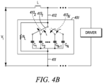
- FIG. 4A is a schematic diagram of an example of the loudspeaker array and transmission lines 400 that is the similar to the structure 300 as shown in FIG. 3 . Similar elements are designated with the same reference numbers.
- the capacitors C1-C18 as shown in FIG. 3 are replaced by sub-circuits 401 1 - 401 18 .
- the sub-circuits 401 1 - 401 18 include various elements that are controllable, e.g., using a controller circuit (not shown), to control each output supplied to each driver of the first driver group 303 and the second driver group 304.
- the sub-circuits 401 1 - 401 18 include at least one capacitor, e.g., C 1 -C N .
- the capacitors may be the same as one of the capacitors C1-C18 in FIG. 3 , but in a single sub-circuit.
- the sub-circuit 401 includes a first terminal 411 that connects to the common terminal of the transmission line 305 or the common terminal of the transmission line 307.
- the circuit includes a second terminal 412 that connects to the input terminal from the transmission line 305 or the common terminal of the transmission line 307 to the associated driver 302.
- a plurality of circuit elements e.g., capacitors C 1 , C 2 , C N-1 and C N , are provided that can control the amount of delay to the drivers in the associated driver group.
- Other circuit elements can be included, e.g., in place of a capacitor or with the capacitor.
- Such other circuit elements can include an active element, e.g., a transistor.
- the circuit elements can be selectively part of the active circuit in the delay circuit (e.g., sub-circuit 401) using switches 413 1 - 413 N .
- the switches 413 1 - 413 N selectively connect the circuit elements between the terminals 411, 412.
- each of the switches 413 1 - 413 N can be individually activated (e.g., switched by a controller), thus there are N 2 combinations of settings for the delay circuit (e.g., sub-circuit 401).
- both switches 413 1 and 413 2 are open, (b) switch 413 1 is closed and switch 413 2 is open, (c) switch 413 1 is open and switch 413 2 is closed, and (d) both switches 413 1 and 413 2 are closed.
- the first combination does not have either of the circuit elements C 1 , C 2 as part of the delay circuit.
- the second combination has the circuit element C 1 in the delay circuit and does not have the circuit element C 2 as part of the delay circuit 401.
- the third combination has the circuit element C 2 in the delay circuit and does not have the circuit element C 1 as part of the delay circuit.
- the fourth combination has both circuit elements C 1 , C 2 as part of the delay circuit.
- the present embodiment allows the delay networks to be programmed to control the delay to any individual driver 302 on an individual basis.
- the top driver group can provide a different beam than the bottom driver group.
- FIG. 4C is a view similar to FIG. 4B but showing circuitry 421 1 - 421 N replaces the capacitors C 1 -C N .
- Circuitry 421 1 - 421 N can include any circuit element that is used in a transmission line to control the electrical signal transmitted thereby.
- the circuitry 421 1 - 421 N includes an inductor.
- the circuitry 421 1 - 421 N includes a resistor, inductor, capacitor (RLC) circuit.
- active circuit elements are part of at least one circuitry 421 1 - 421 N .
- each circuitry 421 1 - 421 N is the same and adding in additional circuity adds to the signal processing.
- At least one of the circuitries 421 1 - 421 N is different than other circuitries.
- Each circuitry 421 1 - 421 N is selectively connected to be electrically conductive within the transmission line, e.g., by the connection of switches 413.
- each stage with one of the circuitry 421 1 - 421 N can have a different electrical effect on the signal, e.g., a delay, sent to its associated driver relative to another of the circuitry 421 1 - 421 N .
- FIG. 4D is a view similar to FIG. 4B but showing a plurality of switchable inductors L 1 , L 2 , ... L N-1 , L N replacing the inductor L of FIG. 4B . While shown as inductors L 1 -L N it is also within the scope of the present disclosure to use circuitry 421 1 - 421 N in place of the inductors L 1 -L N and can include any circuit element that is used in a transmission line to control the electrical signal transmitted thereby. Each inductors L 1 -L N is selectively connected to be electrically conductive within the transmission line, e.g., by the connection of switches 431 1 - 431 N .
- each stage with one of the switchable inductors L 1 -L N can have a different electrical effect on the signal sent to its associated driver relative to another of stages. It will be appreciated that at least one of the inductors L 1 -L N is inline or switched to conducting as this connection feeds the Vi signal to the next stage as well as the associated driver.
- the transmission lines 305, 307 include an audio input signal generator coupled to the input of the transmission line to provide the input signal Vi.
- the signal is progressively or selectively attenuated.
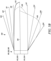
- FIG. 5A is a graph 500 illustrating the exemplary beam patterns that can be generated by a system or loudspeaker 100, 200 or 300.
- a center axis is shown at 501.
- a wide beam pattern 503 is shown within a top wide beam boundary 504 and a bottom wide beam boundary 505.
- a short throw beam pattern 506 is shown within a medium top boundary 507 and a medium bottom boundary 508.
- a long throw beam pattern 510 is shown within a long throw top boundary 511 and a long throw bottom boundary 512.
- a narrow beam pattern 515 is shown within a narrow top boundary 516 and a narrow bottom boundary 517.
- the top driver group 103, 303 may have a delay that is different from the bottom driver group 103, 304.
- the top part, e.g., half, of any beam pattern 503, 506, 510, and 515 is above the center line or plane, which can include the center axis 501.
- the bottom part, e.g., half, of any beam pattern 503, 506, 510, and 515 is below the center line.
- each of the driver groups 103, 303 and 104, 304 are controlled by a separate feed circuit or transmission line, which may be individually programmable.
- FIG. 5B is a graph 500B illustrating a top beam pattern 515 that is different than the bottom beam pattern 503.
- the top beam pattern 515 is produced by the top driver group 103 or 303 and is a narrow beam pattern.
- the bottom beam pattern 503 is produced by the bottom driver group 104 or 304 and is a downfill (wide) beam pattern. These beam patterns are shown in their ideal state about the center axis 501. However, there will be cross over or blending of the beam patterns 515, 503 adj acent the center axis 501.
- the real beam 520 will be a combination of the two beam patterns 515, 503 adjacent the center axis 501.
- FIGS. 5A and 5B show performance of a vertically oriented loudspeaker.
- the loudspeaker arrays may also be oriented horizontally.
- the term 'beamwidth' refers to a width in the direction of the array configuration.
- the loudspeaker array may include a housing that encloses the plurality of driver groups.
- the housing may be a single housing that forms a linear array of drivers (e.g., transducers).
- the loudspeaker may provide a unitary solution to providing improved acoustic coverage by having different beam patterns from different driver groups.
- the different beam patters may be produced by controlling each driver group using the networks and the delay stages or delay elements. In an example, coverage may be providing a uniform sound pressure level in the space that may not be of uniform shape.
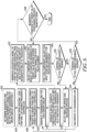
- FIG. 6 is a flowchart depicting operation of an example of a method for providing an asymmetrical coverage pattern using a linear loudspeaker array, e.g., 100, 200 or 300.
- the method illustrated in FIG. 6 may be implemented using a computer program having a user interface that permits user interaction for setting component values (e.g., controlling the switches in the sub-circuit 401), loudspeaker positions, configuring views for data analysis, and setting any other parameter.
- the computer program may be developed as an application using a suitable programming language, or may be implemented as a macro or a sequence of instructions in an application such as a spreadsheet, a database, or suitable alternatives.
- the method allows a user to determine component values for use in a selected network to create the asymmetrical coverage pattern with a linearly arranged loudspeaker array.
- the method also allows the user to optimize performance of the network by ensuring that a constant beam width is achieved at a desired level over the desired frequency range for both the top, first driver group 103, 303 and the bottom, second driver group 104, 304.
- the desired beamwidth and the desired bandwidth are determined for both the first driver group and the second driver group.
- the beamwidth and bandwidth specifications may be entered into memory, or may be requested from the user via a user interface query.
- the user interface query may be a menu-driven interface, an electronic form, or any suitable alternative form of data entry.
- the driver spacing is determined in the driver groups.
- the spacing is the distance between the drivers.
- the driver spacing may be provided in memory or requested from the user via a user interface. In general, the driver spacing should be less than one wavelength ( ⁇ ) of the highest frequency being controlled.
- the number of drivers to be used in the groups in the linear array is determined, driver spacing is determined.
- the number of drivers may be provided in memory or requested from the user via a user interface. In general, the number of drivers in each group should be selected so that the height of the linear array is longer than one wavelength ( ⁇ ) of the lowest frequency being controlled.
- transmission lines are generated for the driver groups, respectively.
- the transmission line may be defined by the topology of the stages, the components and component values.
- the configuration of each stage may be pre-defined in memory and offered to the user as alternatives from which to choose.
- a model transfer function is generated for the group delay or the attenuation at each transducer by a stage of the transmission line.
- the group delay or attenuation is generated as a function of frequency.
- the transfer function may be generated as a graph, but may be any user readable output. This is also done for each group.
- an acoustical model illustrating how the transducers will sum in space is generated.
- the model includes separate drive groups for at least a top part of the space and the bottom part of the space.
- the model includes the group delay or attenuation, and may be displayed as beamwidth vs. the frequency for each driver group.
- the component values of the components in the stages of the transmission line may be adjusted to obtain a constant beamwidth over the desired frequency range.
- the component values may be selected from a broad range of values for each component.
- the values are selected to provide a near constant beamwidth at the desired frequency range.
- An initial set of values are selected for optimization by further fine tuning of the values.
- the adjusting or the optimizing may be done using the switches to control each delay circuit (e.g., 401) for each driver, e.g., transducer.
- Step 616 the component values are fine-tuned for the best beamwidth for the particular part of the space that each driver group is addressing.
- Step 616 can perform a local search.
- a computational optimizer may be used in step 616 to fine tune the values until values are found that result in the most constant beamwidth at the target value over the required range.
- the switches may select the delay for each driver in a driver group to achieve the desired beam pattern, e.g., beamwidth.
- Optimizers have an initial condition (or a seed), and will find the local minima, maxima, or fixed values.
- the computational optimizer may use the component values found in step 614 as a seed.
- the acoustical model is checked to determine if it controls up to the highest frequency. If it does not ("No" branch), a smaller driver and driver spacing are selected at step 620 and the method goes back to step 606. If control up to the highest frequency is attained ("Yes” branch), the acoustical model is checked to determine if it controls down to the lowest frequency at decision block 622. If it is not ("No” branch), additional drivers are added to the transmission line at step 624. The method then continues to step 608 to generate a new transmission line. If control to the lowest frequency is attained at decision block 622 ("Yes" branch), the beamwidth is checked over the entire range at the target value. If the beamwidth is not constant (“No” branch), new seed component values are selected at step 614. If the beamwidth is constant ("Yes” branch), the design is complete.
- the loudspeaker array includes a plurality of loudspeakers, each with a plurality of driver groups.
- a feed circuit e.g., the transmission line, is included for each driver group.
- the transmission line has a plurality of stages. Each stage has a stage input and a stage output. The stage output of each stage is coupled to the stage input of a next stage. Each stage output is also connected to at least one of the plurality of drivers or loudspeakers.
- the stage input of the first stage is coupled to an audio signal input.
- Each stage is configured to add an electrical delay of the audio signal for each subsequent stage or other signal processing at each stage for a group of drivers. The electrical delay is adjusted such that the plurality of loudspeakers generates sound in a desired radiation pattern.
Landscapes
- Physics & Mathematics (AREA)
- Engineering & Computer Science (AREA)
- Acoustics & Sound (AREA)
- Signal Processing (AREA)
- Health & Medical Sciences (AREA)
- Otolaryngology (AREA)
- General Health & Medical Sciences (AREA)
- Circuit For Audible Band Transducer (AREA)
- Obtaining Desirable Characteristics In Audible-Bandwidth Transducers (AREA)
Claims (14)
- Lautsprecher (102; 302), umfassend:eine erste Gruppe (103; 303) von Treibern (102a-102j; 302a-302j) zum Ausgeben eines ersten Strahlmusters (515);eine erste angezapfte Übertragungsleitung (105; 305), die einen Eingang zu der ersten Gruppe (103; 303) von Treibern (102a-102j; 302a-302j) steuert;eine zweite Gruppe (104; 304) von Treibern (102k-102t; 302k-302t), die sich von der ersten Gruppe (103; 303) von Treibern (102a-102j; 302a-302j) unterscheidet, wobei die zweite Gruppe (104; 304) von Treibern (102k-102t; 302k-302t) konfiguriert ist, um ein zweites Strahlmuster (503) auszugeben; undeine zweite angezapfte Übertragungsleitung (107; 307), die einen Eingang zu der zweiten Gruppe (104; 304) von Treibern (102k-102t; 302k-302t) steuert, wobei sich die zweite angezapfte Übertragungsleitung (107; 307) von der ersten angezapften Übertragungsleitung (105; 305) unterscheidet;wobei die erste angezapfte Übertragungsleitung (105; 305) eine Vielzahl von Verarbeitungsstufen beinhaltet, die einer Anzahl der ersten Gruppe (103; 303) von Treibern (102a-102j; 302a-302j) entspricht;wobei die zweite angezapfte Übertragungsleitung (107; 307) eine Vielzahl von Verzögerungsstufen (108j-t) beinhaltet, die einer Anzahl der zweiten Gruppe (104; 304) von Treibern (102k-102t; 302k-302t) entspricht,wobei das erste Strahlmuster (515) ein schmaler Strahl ist und das zweite Strahlmuster (503) ein breites Strahlmuster ist, das breiter ist als der schmale Strahl des ersten Strahlmusters (515), undwobei jede der Treibergruppen (103, 104; 303, 304) durch eine separate Übertragungsleitung gesteuert wird und die Strahlmuster (503, 515) für jede der Gruppen von Treibern durch eine einzelne Übertragungsleitung gesteuert werden.
- Lautsprecher (102; 302) nach Anspruch 1, wobei die erste angezapfte Übertragungsleitung (105; 305) eine Vielzahl von Verzögerungsstufen (108a-i) beinhaltet, die einer Anzahl der ersten Gruppe (103; 303) von Treibern (102a-102j; 302a-302j) entspricht; und wobei die zweite angezapfte Übertragungsleitung (107; 307) eine Vielzahl von Verzögerungsstufen (108j-t) beinhaltet, die einer Anzahl der zweiten Gruppe (104; 304) von Treibern (102k-102t; 302k-302t) entspricht.
- Lautsprecher (102; 302) nach Anspruch 2, wobei die Vielzahl von Verzögerungsstufen (108a-t) programmierbar ist, um eine Verzögerung an der Vielzahl von Verzögerungsstufen (108a-t) zu steuern.
- Lautsprecher (102; 302) nach Anspruch 3, wobei mindestens eine der Vielzahl von Verzögerungsstufen (108a-t) eine Vielzahl von Schaltungselementen beinhaltet, die selektiv leitend ist, um die Verzögerung der mindestens einen der Vielzahl von Verzögerungsstufen (108a-108t) zu programmieren.
- Lautsprecher (102; 302) nach Anspruch 4, wobei die mindestens eine der Verzögerungsstufen (108a-108t) einen Schalter beinhaltet, der selektiv mindestens eines der Vielzahl von Schaltungselementen verbindet, um eine Auswahlverzögerung bereitzustellen.
- Lautsprecher (102; 302) nach Anspruch 5, wobei die Vielzahl von Schaltungselementen nur passive Elemente beinhaltet.
- Lautsprecher (102; 302) nach Anspruch 1, wobei das erste Strahlmuster (515) und das zweite Strahlmuster (503) asymmetrisch zueinander sind und mit Asymmetrie von der ersten Gruppe (103; 303) von Treibern (102a-102j; 302a-302j) bzw. der zweiten Gruppe (104; 304) von Treibern (102k-102t; 302k-302t) gesteuert werden.
- Lautsprecher (102; 302) nach Anspruch 1, wobei die Vielzahl von Verarbeitungsstufen dazu konfiguriert ist, eine Verarbeitung einer Audioeingangssignalverzögerung zu steuern; und wobei mindestens eine der Vielzahl von Verarbeitungsstufen eine Vielzahl von Schaltungselementen beinhaltet, die selektiv leitend ist, um die Verarbeitung einer Verarbeitungsstufe der Vielzahl von Verarbeitungsstufen einzustellen.
- Lautsprecher (102; 302) nach Anspruch 8, wobei mindestens eine Verarbeitungsstufe der Vielzahl von Verarbeitungsstufen einen Schalter (4131-413n) beinhaltet, der selektiv mindestens eines der Vielzahl von Schaltungselementen verbindet, um eine selektive Signalverarbeitung für einen jeweiligen einen der Treiber der ersten Gruppe (103; 303) von Treibern (102a-102j; 302a-302j) bereitzustellen.
- Lautsprecherarray (102; 302), umfassend:einen Lautsprecher (102; 302) nach einem der Ansprüche 1-9,wobei die erste angezapfte Übertragungsleitung (105; 305) eine Vielzahl von ersten Stufen (108a-108i) aufweist, die mit der ersten Gruppe (103; 303) von Treibern (102a-102j; 302a-302j) verbunden ist, wobei jede erste Stufe der Vielzahl von ersten Stufen (108a-108i) einen Eingang der ersten Stufe und einen Ausgang der ersten Stufe aufweist, wobei der Ausgang der ersten Stufe jeder ersten Stufe der Vielzahl von ersten Stufen (108a-108i), mit Ausnahme eines letzten Ausgangs der ersten Stufe, mit dem Eingang der ersten Stufe einer nächsten ersten Stufe und mit mindestens einem Treiber der ersten Gruppe (103; 303) von Treibern (102a-102j; 302a-302j) gekoppelt ist, wobei der Eingang der ersten Stufe einer ersten Stufe mit einem Audiosignaleingang gekoppelt ist, wobei jede erste Stufe einen LC-Zweig beinhaltet, bei dem mindestens eine erste Induktivität mit dem Eingang der ersten Stufe und dem Ausgang der ersten Stufe in Reihe geschaltet ist, und mindestens ein erster Kondensator mit dem Ausgang der ersten Stufe parallel zu dem mindestens einen einer Vielzahl von Treibern der ersten Gruppe (103; 303) von Treibern (102a-102j; 302a-302j) verbunden ist;wobei die zweite angezapfte Übertragungsleitung (107; 307) eine Vielzahl von zweiten Stufen (108j-108r) aufweist, die mit der zweiten Gruppe (104; 304) von Treibern (102k-102t; 302k-302t) verbunden sind, wobei jede zweite Stufe der Vielzahl von zweiten Stufen (108j-108r) einen Eingang der zweiten Stufe und einen Ausgang der zweiten Stufe aufweist, wobei der Ausgang der zweiten Stufe jeder zweiten Stufe der Vielzahl von zweiten Stufen (108j-108r), mit Ausnahme eines letzten Ausgangs der zweiten Stufe, mit dem Eingang der zweiten Stufe einer nächsten zweiten Stufe und mit mindestens einem der zweiten Gruppe (104; 304) von Treibern (102k-102t; 302k-302t) gekoppelt ist, wobei der Eingang der zweiten Stufe einer zweiten Stufe mit einem Audiosignaleingang gekoppelt ist, wobei jede zweite Stufe einen LC-Zweig beinhaltet, bei dem mindestens eine zweite Induktivität mit dem Eingang der zweiten Stufe und dem Ausgang der zweiten Stufe in Reihe geschaltet ist, und mindestens ein zweiter Kondensator mit dem Ausgang der zweiten Stufe parallel zu dem mindestens einen einer Vielzahl von Treibern der zweiten Gruppe (104; 304) von Treibern (102k-102t; 302k-302t) verbunden ist; undwobei jede erste Stufe der Vielzahl von ersten Stufen (108a-108i) und jede zweite Stufe der Vielzahl von zweiten Stufen (108j-108r) dazu konfiguriert ist, jeweils eine elektrische Verzögerung zu jeder nachfolgenden Stufe hinzuzufügen, wobei die elektrische Verzögerung so angepasst wird, dass die erste Gruppe (103; 303) von Treibern (102a-102j; 302a-302j) und die zweite Gruppe (104; 304) von Treibern (102k-102t; 302k-302t) Schall in einem gewünschten asymmetrischen Strahlungsmuster erzeugen, das eine Summe aus dem ersten Strahlmuster (515) und dem zweiten Strahlmuster (503) ist, wobei das erste Strahlmuster (515) und das zweite Strahlmuster (503) relativ zueinander asymmetrisch sind,wobei das erste Strahlmuster (515) dazu konfiguriert ist, einem ersten Volumen einer Umgebung benachbart zu dem Lautsprecherarray (102; 302) Schall bereitzustellen; undwobei das zweite Strahlmuster (503) dazu konfiguriert ist, einem zweiten Volumen einer Umgebung benachbart zu dem Lautsprecherarray (102; 302) Schall bereitzustellen.
- Lautsprecherarray (102; 302) nach Anspruch 10, wobei die erste Gruppe (103; 303) von Treibern (102a-102j; 302a-302j) in einem ersten linearen Array angeordnet ist, das einen ersten Treiber (102j; 302j) aufweist, der an einem Ende des ersten linearen Arrays positioniert ist, das ein Eingangssignal (Vi) von der ersten angezapften Übertragungsleitung (105; 305) empfängt, wobei der Ausgang der ersten Stufe des ersten Treibers (102j; 302j) mit dem Eingangssignal (Vi) verbunden ist.
- Lautsprecherarray (102; 302) nach Anspruch 11, wobei die zweite Gruppe (104; 304) von Treibern (102k-102t; 302k-302t) in einem zweiten linearen Array angeordnet ist, das einen zweiten Treiber (102k; 302k) aufweist, der an einem Ende des zweiten linearen Arrays positioniert ist, das ein Eingangssignal (Vi) von der zweiten angezapften Übertragungsleitung (107; 307) empfängt, wobei der Ausgang der zweiten Stufe des zweiten Treibers (102j; 302j) mit dem Eingangssignal (Vi) verbunden ist.
- Lautsprecherarray (102; 302) nach Anspruch 12, wobei der erste Treiber und der zweite Treiber voneinander entfernt sind.
- Lautsprecherarray (102; 302) nach Anspruch 13, wobei der erste Treiber und der zweite Treiber in einer Mitte des Lautsprecherarrays (102; 302) benachbart sind.
Applications Claiming Priority (2)
| Application Number | Priority Date | Filing Date | Title |
|---|---|---|---|
| US15/164,297 US9955260B2 (en) | 2016-05-25 | 2016-05-25 | Asymmetrical passive group delay beamforming |
| PCT/US2017/034481 WO2017205628A1 (en) | 2016-05-25 | 2017-05-25 | Asymmetrical passive group delay beamforming |
Publications (3)
| Publication Number | Publication Date |
|---|---|
| EP3466112A1 EP3466112A1 (de) | 2019-04-10 |
| EP3466112A4 EP3466112A4 (de) | 2019-12-18 |
| EP3466112B1 true EP3466112B1 (de) | 2023-04-12 |
Family
ID=60411619
Family Applications (1)
| Application Number | Title | Priority Date | Filing Date |
|---|---|---|---|
| EP17803586.1A Active EP3466112B1 (de) | 2016-05-25 | 2017-05-25 | Asymmetrische passive gruppenverzögerungsstrahlformung |
Country Status (4)
| Country | Link |
|---|---|
| US (1) | US9955260B2 (de) |
| EP (1) | EP3466112B1 (de) |
| CN (1) | CN109155886B (de) |
| WO (1) | WO2017205628A1 (de) |
Families Citing this family (5)
| Publication number | Priority date | Publication date | Assignee | Title |
|---|---|---|---|---|
| CN108464012B (zh) | 2016-01-14 | 2020-04-07 | 哈曼国际工业有限公司 | 具有浮动波导的双向扬声器 |
| DE112017000382T5 (de) * | 2016-01-14 | 2018-09-27 | Harman International Industries, Incorporated | Schallstrahlungsmustersteuerung |
| US10531196B2 (en) * | 2017-06-02 | 2020-01-07 | Apple Inc. | Spatially ducking audio produced through a beamforming loudspeaker array |
| US12047738B1 (en) | 2021-07-30 | 2024-07-23 | Perlisten Audio Llc | Directivity pattern control waveguide for a speaker, and speaker including a directivity pattern control waveguide |
| US12041414B1 (en) | 2023-08-15 | 2024-07-16 | Perlisten Audio Llc | Directivity pattern control waveguide for a speaker, and speaker including a directivity pattern control waveguide |
Family Cites Families (41)
| Publication number | Priority date | Publication date | Assignee | Title |
|---|---|---|---|---|
| US1643323A (en) | 1921-01-04 | 1927-09-27 | American Telephone & Telegraph | Directive antenna array |
| US3068431A (en) | 1959-01-02 | 1962-12-11 | Alford Andrew | Variable delay line |
| US3125181A (en) | 1961-06-21 | 1964-03-17 | pawlowski | |
| US3299206A (en) | 1963-07-24 | 1967-01-17 | Bolt Beranek & Newman | Line-source loudspeakers |
| JPS5639757B2 (de) | 1975-03-03 | 1981-09-16 | ||
| US4330691A (en) | 1980-01-31 | 1982-05-18 | The Futures Group, Inc. | Integral ceiling tile-loudspeaker system |
| JPS57192195A (en) | 1981-05-15 | 1982-11-26 | Beard Terry D | Electric-acoustic transducer |
| US4845759A (en) | 1986-04-25 | 1989-07-04 | Intersonics Incorporated | Sound source having a plurality of drivers operating from a virtual point |
| JPH0541897A (ja) | 1991-08-07 | 1993-02-19 | Pioneer Electron Corp | スピーカ装置およびその指向性制御方法 |
| NL9401860A (nl) * | 1994-11-08 | 1996-06-03 | Duran Bv | Luidsprekersysteem met bestuurde richtinggevoeligheid. |
| GB9506263D0 (en) * | 1995-03-28 | 1995-05-17 | Sse Hire Limited | Loudspeaker system |
| DE19739425A1 (de) | 1997-09-09 | 1999-03-11 | Bosch Gmbh Robert | Verfahren und Anordnung zur Wiedergabe eines sterophonen Audiosignals |
| US7092675B2 (en) | 1998-05-29 | 2006-08-15 | Silicon Laboratories | Apparatus and methods for generating radio frequencies in communication circuitry using multiple control signals |
| US7260235B1 (en) | 2000-10-16 | 2007-08-21 | Bose Corporation | Line electroacoustical transducing |
| US20020131608A1 (en) | 2001-03-01 | 2002-09-19 | William Lobb | Method and system for providing digitally focused sound |
| US7826622B2 (en) | 2003-05-27 | 2010-11-02 | Harman International Industries, Incorporated | Constant-beamwidth loudspeaker array |
| JP4154601B2 (ja) | 2003-10-23 | 2008-09-24 | ソニー株式会社 | 信号変換装置、出力アンプ装置、オーディオ装置および送受信システム |
| KR101086398B1 (ko) | 2003-12-24 | 2011-11-25 | 삼성전자주식회사 | 다수의 마이크로폰을 이용한 지향성 제어 가능 스피커시스템 및 그 방법 |
| US7760891B2 (en) | 2004-03-16 | 2010-07-20 | Xerox Corporation | Focused hypersonic communication |
| US7720232B2 (en) * | 2004-10-15 | 2010-05-18 | Lifesize Communications, Inc. | Speakerphone |
| US8351616B1 (en) * | 2005-11-23 | 2013-01-08 | Graber Curtis E | Array of multiple LF transducers with ultrahigh cardioid sound pattern generation |
| JP4867565B2 (ja) * | 2005-11-29 | 2012-02-01 | セイコーエプソン株式会社 | 容量性負荷の駆動回路、および超音波スピーカ |
| WO2008115284A2 (en) * | 2006-10-16 | 2008-09-25 | Thx Ltd. | Loudspeaker line array configurations and related sound processing |
| JP2008113195A (ja) * | 2006-10-30 | 2008-05-15 | Mitsubishi Electric Engineering Co Ltd | スピーカシステム |
| WO2008135887A1 (en) * | 2007-05-03 | 2008-11-13 | Koninklijke Philips Electronics N.V. | Stereo sound rendering system |
| US9031267B2 (en) * | 2007-08-29 | 2015-05-12 | Microsoft Technology Licensing, Llc | Loudspeaker array providing direct and indirect radiation from same set of drivers |
| WO2009138936A1 (en) * | 2008-05-15 | 2009-11-19 | Koninklijke Philips Electronics N.V. | A surround sound reproduction system |
| US8971547B2 (en) * | 2009-01-08 | 2015-03-03 | Harman International Industries, Incorporated | Passive group delay beam forming |
| US8351617B2 (en) * | 2009-01-13 | 2013-01-08 | Fortemedia, Inc. | Method for phase mismatch calibration for an array microphone and phase calibration module for the same |
| US10966006B2 (en) * | 2010-12-31 | 2021-03-30 | Nokia Technologies Oy | Apparatus and method for a sound generating device combined with a display unit |
| US8712340B2 (en) | 2011-02-18 | 2014-04-29 | Blackberry Limited | Method and apparatus for radio antenna frequency tuning |
| CN102404672B (zh) * | 2011-10-27 | 2013-12-18 | 苏州上声电子有限公司 | 数字化扬声器阵列系统的通道均衡与波束控制方法和装置 |
| CN102438190A (zh) * | 2011-12-14 | 2012-05-02 | 南京琅声声学科技有限公司 | 一种辐射角灵活可调的扬声器组及设置方法 |
| KR101708522B1 (ko) * | 2012-05-31 | 2017-02-20 | 한국전자통신연구원 | 오디오 신호 처리 방법 및 장치, 오디오 재생 시스템 |
| EP2974356B1 (de) * | 2013-03-13 | 2020-05-06 | THX Ltd | Flacher lautsprecher |
| EP3038385B1 (de) * | 2013-08-19 | 2018-11-14 | Yamaha Corporation | Lautsprechervorrichtung und verfahren zur tonsignalverarbeitung |
| JP2015046759A (ja) * | 2013-08-28 | 2015-03-12 | 三菱電機株式会社 | ビームフォーミング処理装置およびビームフォーミング処理方法 |
| CN103594807B (zh) * | 2013-11-29 | 2016-03-23 | 东南大学 | 薄基片幅度校正宽带差波束平面喇叭天线 |
| KR102206739B1 (ko) * | 2013-12-20 | 2021-01-25 | 삼성전자주식회사 | 수신기, 이의 동작 방법, 및 이를 포함하는 빔포밍 레이더 시스템 |
| US20150312693A1 (en) * | 2014-04-23 | 2015-10-29 | William E. Collins | Phase-unified loudspeakers: series crossovers |
| EP3113367A1 (de) * | 2015-07-03 | 2017-01-04 | Rohde & Schwarz GmbH & Co. KG | Verzögerungsleitungssystem, hochfrequenzprobennehmer, analog-digital-wandler und oszilloskop |
-
2016
- 2016-05-25 US US15/164,297 patent/US9955260B2/en active Active
-
2017
- 2017-05-25 EP EP17803586.1A patent/EP3466112B1/de active Active
- 2017-05-25 WO PCT/US2017/034481 patent/WO2017205628A1/en not_active Ceased
- 2017-05-25 CN CN201780032026.6A patent/CN109155886B/zh active Active
Also Published As
| Publication number | Publication date |
|---|---|
| EP3466112A1 (de) | 2019-04-10 |
| CN109155886B (zh) | 2021-06-08 |
| WO2017205628A1 (en) | 2017-11-30 |
| US9955260B2 (en) | 2018-04-24 |
| EP3466112A4 (de) | 2019-12-18 |
| US20170347191A1 (en) | 2017-11-30 |
| CN109155886A (zh) | 2019-01-04 |
Similar Documents
| Publication | Publication Date | Title |
|---|---|---|
| EP3466112B1 (de) | Asymmetrische passive gruppenverzögerungsstrahlformung | |
| US9426562B2 (en) | Passive group delay beam forming | |
| DE102009010278B4 (de) | Lautsprecher | |
| US8842866B2 (en) | Loudspeaker system with reduced rear sound radiation | |
| US8781136B2 (en) | Loudspeaker array system | |
| KR102468272B1 (ko) | 음향 출력 장치 및 그 제어 방법 | |
| US6513622B1 (en) | Full-range loudspeaker system for cinema screen | |
| CN107079217A (zh) | 具有窄分散度的扩音器 | |
| CN108464013B (zh) | 声音墙 | |
| CN108464011B (zh) | 声学辐射图控制 | |
| WO2007127757A2 (en) | Method and system for surround sound beam-forming using the overlapping portion of driver frequency ranges | |
| US10356519B2 (en) | Audio monitor signal interception device | |
| JP2006191285A (ja) | アレイスピーカシステムおよびそのオーディオ信号処理装置 | |
| US20080044038A1 (en) | Stereophonic sound system | |
| CN110915230B (zh) | 恒定方向性双向楔形扬声器系统 | |
| US6707919B2 (en) | Driver control circuit | |
| US10735859B2 (en) | Line array speaker with frequency-dependent electrical tapering optimized for midrange and high frequency reproduction in the nearfield | |
| US9154878B2 (en) | Interconnected speaker system | |
| RU2799663C1 (ru) | Фильтр для многополосной акустической системы | |
| EP4655952A1 (de) | Verfahren zur verarbeitung von lautsprecherarray-audiosignalen | |
| Fincham | Multiple-driver loudspeaker systems | |
| HK40025434A (en) | Constant-directivity two way wedge loudspeaker system | |
| HK40025434B (en) | Constant-directivity two way wedge loudspeaker system | |
| CN112135225A (zh) | 扬声器系统和电子设备 | |
| EP1802163A1 (de) | Lautsprecheranordnung |
Legal Events
| Date | Code | Title | Description |
|---|---|---|---|
| STAA | Information on the status of an ep patent application or granted ep patent |
Free format text: STATUS: THE INTERNATIONAL PUBLICATION HAS BEEN MADE |
|
| PUAI | Public reference made under article 153(3) epc to a published international application that has entered the european phase |
Free format text: ORIGINAL CODE: 0009012 |
|
| STAA | Information on the status of an ep patent application or granted ep patent |
Free format text: STATUS: REQUEST FOR EXAMINATION WAS MADE |
|
| 17P | Request for examination filed |
Effective date: 20181121 |
|
| AK | Designated contracting states |
Kind code of ref document: A1 Designated state(s): AL AT BE BG CH CY CZ DE DK EE ES FI FR GB GR HR HU IE IS IT LI LT LU LV MC MK MT NL NO PL PT RO RS SE SI SK SM TR |
|
| AX | Request for extension of the european patent |
Extension state: BA ME |
|
| DAV | Request for validation of the european patent (deleted) | ||
| DAX | Request for extension of the european patent (deleted) | ||
| REG | Reference to a national code |
Ref country code: DE Ref legal event code: R079 Ref document number: 602017067694 Country of ref document: DE Free format text: PREVIOUS MAIN CLASS: H04R0003000000 Ipc: H04R0001400000 |
|
| A4 | Supplementary search report drawn up and despatched |
Effective date: 20191119 |
|
| RIC1 | Information provided on ipc code assigned before grant |
Ipc: H04R 3/12 20060101ALI20191113BHEP Ipc: H04S 7/00 20060101ALI20191113BHEP Ipc: H04R 1/40 20060101AFI20191113BHEP Ipc: H04R 3/14 20060101ALI20191113BHEP |
|
| STAA | Information on the status of an ep patent application or granted ep patent |
Free format text: STATUS: EXAMINATION IS IN PROGRESS |
|
| 17Q | First examination report despatched |
Effective date: 20200827 |
|
| GRAP | Despatch of communication of intention to grant a patent |
Free format text: ORIGINAL CODE: EPIDOSNIGR1 |
|
| STAA | Information on the status of an ep patent application or granted ep patent |
Free format text: STATUS: GRANT OF PATENT IS INTENDED |
|
| INTG | Intention to grant announced |
Effective date: 20221109 |
|
| GRAS | Grant fee paid |
Free format text: ORIGINAL CODE: EPIDOSNIGR3 |
|
| GRAA | (expected) grant |
Free format text: ORIGINAL CODE: 0009210 |
|
| STAA | Information on the status of an ep patent application or granted ep patent |
Free format text: STATUS: THE PATENT HAS BEEN GRANTED |
|
| AK | Designated contracting states |
Kind code of ref document: B1 Designated state(s): AL AT BE BG CH CY CZ DE DK EE ES FI FR GB GR HR HU IE IS IT LI LT LU LV MC MK MT NL NO PL PT RO RS SE SI SK SM TR |
|
| REG | Reference to a national code |
Ref country code: GB Ref legal event code: FG4D |
|
| REG | Reference to a national code |
Ref country code: CH Ref legal event code: EP |
|
| REG | Reference to a national code |
Ref country code: DE Ref legal event code: R096 Ref document number: 602017067694 Country of ref document: DE |
|
| REG | Reference to a national code |
Ref country code: IE Ref legal event code: FG4D |
|
| REG | Reference to a national code |
Ref country code: AT Ref legal event code: REF Ref document number: 1560442 Country of ref document: AT Kind code of ref document: T Effective date: 20230515 |
|
| P01 | Opt-out of the competence of the unified patent court (upc) registered |
Effective date: 20230527 |
|
| REG | Reference to a national code |
Ref country code: LT Ref legal event code: MG9D |
|
| REG | Reference to a national code |
Ref country code: NL Ref legal event code: MP Effective date: 20230412 |
|
| REG | Reference to a national code |
Ref country code: AT Ref legal event code: MK05 Ref document number: 1560442 Country of ref document: AT Kind code of ref document: T Effective date: 20230412 |
|
| PG25 | Lapsed in a contracting state [announced via postgrant information from national office to epo] |
Ref country code: NL Free format text: LAPSE BECAUSE OF FAILURE TO SUBMIT A TRANSLATION OF THE DESCRIPTION OR TO PAY THE FEE WITHIN THE PRESCRIBED TIME-LIMIT Effective date: 20230412 |
|
| PG25 | Lapsed in a contracting state [announced via postgrant information from national office to epo] |
Ref country code: SE Free format text: LAPSE BECAUSE OF FAILURE TO SUBMIT A TRANSLATION OF THE DESCRIPTION OR TO PAY THE FEE WITHIN THE PRESCRIBED TIME-LIMIT Effective date: 20230412 Ref country code: PT Free format text: LAPSE BECAUSE OF FAILURE TO SUBMIT A TRANSLATION OF THE DESCRIPTION OR TO PAY THE FEE WITHIN THE PRESCRIBED TIME-LIMIT Effective date: 20230814 Ref country code: NO Free format text: LAPSE BECAUSE OF FAILURE TO SUBMIT A TRANSLATION OF THE DESCRIPTION OR TO PAY THE FEE WITHIN THE PRESCRIBED TIME-LIMIT Effective date: 20230712 Ref country code: ES Free format text: LAPSE BECAUSE OF FAILURE TO SUBMIT A TRANSLATION OF THE DESCRIPTION OR TO PAY THE FEE WITHIN THE PRESCRIBED TIME-LIMIT Effective date: 20230412 Ref country code: AT Free format text: LAPSE BECAUSE OF FAILURE TO SUBMIT A TRANSLATION OF THE DESCRIPTION OR TO PAY THE FEE WITHIN THE PRESCRIBED TIME-LIMIT Effective date: 20230412 |
|
| PG25 | Lapsed in a contracting state [announced via postgrant information from national office to epo] |
Ref country code: RS Free format text: LAPSE BECAUSE OF FAILURE TO SUBMIT A TRANSLATION OF THE DESCRIPTION OR TO PAY THE FEE WITHIN THE PRESCRIBED TIME-LIMIT Effective date: 20230412 Ref country code: PL Free format text: LAPSE BECAUSE OF FAILURE TO SUBMIT A TRANSLATION OF THE DESCRIPTION OR TO PAY THE FEE WITHIN THE PRESCRIBED TIME-LIMIT Effective date: 20230412 Ref country code: LV Free format text: LAPSE BECAUSE OF FAILURE TO SUBMIT A TRANSLATION OF THE DESCRIPTION OR TO PAY THE FEE WITHIN THE PRESCRIBED TIME-LIMIT Effective date: 20230412 Ref country code: LT Free format text: LAPSE BECAUSE OF FAILURE TO SUBMIT A TRANSLATION OF THE DESCRIPTION OR TO PAY THE FEE WITHIN THE PRESCRIBED TIME-LIMIT Effective date: 20230412 Ref country code: IS Free format text: LAPSE BECAUSE OF FAILURE TO SUBMIT A TRANSLATION OF THE DESCRIPTION OR TO PAY THE FEE WITHIN THE PRESCRIBED TIME-LIMIT Effective date: 20230812 Ref country code: HR Free format text: LAPSE BECAUSE OF FAILURE TO SUBMIT A TRANSLATION OF THE DESCRIPTION OR TO PAY THE FEE WITHIN THE PRESCRIBED TIME-LIMIT Effective date: 20230412 Ref country code: GR Free format text: LAPSE BECAUSE OF FAILURE TO SUBMIT A TRANSLATION OF THE DESCRIPTION OR TO PAY THE FEE WITHIN THE PRESCRIBED TIME-LIMIT Effective date: 20230713 Ref country code: AL Free format text: LAPSE BECAUSE OF FAILURE TO SUBMIT A TRANSLATION OF THE DESCRIPTION OR TO PAY THE FEE WITHIN THE PRESCRIBED TIME-LIMIT Effective date: 20230412 |
|
| PG25 | Lapsed in a contracting state [announced via postgrant information from national office to epo] |
Ref country code: FI Free format text: LAPSE BECAUSE OF FAILURE TO SUBMIT A TRANSLATION OF THE DESCRIPTION OR TO PAY THE FEE WITHIN THE PRESCRIBED TIME-LIMIT Effective date: 20230412 |
|
| REG | Reference to a national code |
Ref country code: CH Ref legal event code: PL |
|
| REG | Reference to a national code |
Ref country code: DE Ref legal event code: R097 Ref document number: 602017067694 Country of ref document: DE |
|
| PG25 | Lapsed in a contracting state [announced via postgrant information from national office to epo] |
Ref country code: SK Free format text: LAPSE BECAUSE OF FAILURE TO SUBMIT A TRANSLATION OF THE DESCRIPTION OR TO PAY THE FEE WITHIN THE PRESCRIBED TIME-LIMIT Effective date: 20230412 |
|
| PG25 | Lapsed in a contracting state [announced via postgrant information from national office to epo] |
Ref country code: MC Free format text: LAPSE BECAUSE OF FAILURE TO SUBMIT A TRANSLATION OF THE DESCRIPTION OR TO PAY THE FEE WITHIN THE PRESCRIBED TIME-LIMIT Effective date: 20230412 |
|
| REG | Reference to a national code |
Ref country code: BE Ref legal event code: MM Effective date: 20230531 |
|
| PG25 | Lapsed in a contracting state [announced via postgrant information from national office to epo] |
Ref country code: SM Free format text: LAPSE BECAUSE OF FAILURE TO SUBMIT A TRANSLATION OF THE DESCRIPTION OR TO PAY THE FEE WITHIN THE PRESCRIBED TIME-LIMIT Effective date: 20230412 Ref country code: SK Free format text: LAPSE BECAUSE OF FAILURE TO SUBMIT A TRANSLATION OF THE DESCRIPTION OR TO PAY THE FEE WITHIN THE PRESCRIBED TIME-LIMIT Effective date: 20230412 Ref country code: RO Free format text: LAPSE BECAUSE OF FAILURE TO SUBMIT A TRANSLATION OF THE DESCRIPTION OR TO PAY THE FEE WITHIN THE PRESCRIBED TIME-LIMIT Effective date: 20230412 Ref country code: MC Free format text: LAPSE BECAUSE OF FAILURE TO SUBMIT A TRANSLATION OF THE DESCRIPTION OR TO PAY THE FEE WITHIN THE PRESCRIBED TIME-LIMIT Effective date: 20230412 Ref country code: LU Free format text: LAPSE BECAUSE OF NON-PAYMENT OF DUE FEES Effective date: 20230525 Ref country code: LI Free format text: LAPSE BECAUSE OF NON-PAYMENT OF DUE FEES Effective date: 20230531 Ref country code: EE Free format text: LAPSE BECAUSE OF FAILURE TO SUBMIT A TRANSLATION OF THE DESCRIPTION OR TO PAY THE FEE WITHIN THE PRESCRIBED TIME-LIMIT Effective date: 20230412 Ref country code: DK Free format text: LAPSE BECAUSE OF FAILURE TO SUBMIT A TRANSLATION OF THE DESCRIPTION OR TO PAY THE FEE WITHIN THE PRESCRIBED TIME-LIMIT Effective date: 20230412 Ref country code: CZ Free format text: LAPSE BECAUSE OF FAILURE TO SUBMIT A TRANSLATION OF THE DESCRIPTION OR TO PAY THE FEE WITHIN THE PRESCRIBED TIME-LIMIT Effective date: 20230412 Ref country code: CH Free format text: LAPSE BECAUSE OF NON-PAYMENT OF DUE FEES Effective date: 20230531 |
|
| PLBE | No opposition filed within time limit |
Free format text: ORIGINAL CODE: 0009261 |
|
| STAA | Information on the status of an ep patent application or granted ep patent |
Free format text: STATUS: NO OPPOSITION FILED WITHIN TIME LIMIT |
|
| REG | Reference to a national code |
Ref country code: IE Ref legal event code: MM4A |
|
| 26N | No opposition filed |
Effective date: 20240115 |
|
| PG25 | Lapsed in a contracting state [announced via postgrant information from national office to epo] |
Ref country code: IE Free format text: LAPSE BECAUSE OF NON-PAYMENT OF DUE FEES Effective date: 20230525 |
|
| PG25 | Lapsed in a contracting state [announced via postgrant information from national office to epo] |
Ref country code: IE Free format text: LAPSE BECAUSE OF NON-PAYMENT OF DUE FEES Effective date: 20230525 |
|
| PG25 | Lapsed in a contracting state [announced via postgrant information from national office to epo] |
Ref country code: SI Free format text: LAPSE BECAUSE OF FAILURE TO SUBMIT A TRANSLATION OF THE DESCRIPTION OR TO PAY THE FEE WITHIN THE PRESCRIBED TIME-LIMIT Effective date: 20230412 |
|
| PG25 | Lapsed in a contracting state [announced via postgrant information from national office to epo] |
Ref country code: SI Free format text: LAPSE BECAUSE OF FAILURE TO SUBMIT A TRANSLATION OF THE DESCRIPTION OR TO PAY THE FEE WITHIN THE PRESCRIBED TIME-LIMIT Effective date: 20230412 Ref country code: IT Free format text: LAPSE BECAUSE OF FAILURE TO SUBMIT A TRANSLATION OF THE DESCRIPTION OR TO PAY THE FEE WITHIN THE PRESCRIBED TIME-LIMIT Effective date: 20230412 Ref country code: FR Free format text: LAPSE BECAUSE OF NON-PAYMENT OF DUE FEES Effective date: 20230612 Ref country code: BE Free format text: LAPSE BECAUSE OF NON-PAYMENT OF DUE FEES Effective date: 20230531 |
|
| PG25 | Lapsed in a contracting state [announced via postgrant information from national office to epo] |
Ref country code: BG Free format text: LAPSE BECAUSE OF FAILURE TO SUBMIT A TRANSLATION OF THE DESCRIPTION OR TO PAY THE FEE WITHIN THE PRESCRIBED TIME-LIMIT Effective date: 20230412 |
|
| PG25 | Lapsed in a contracting state [announced via postgrant information from national office to epo] |
Ref country code: BG Free format text: LAPSE BECAUSE OF FAILURE TO SUBMIT A TRANSLATION OF THE DESCRIPTION OR TO PAY THE FEE WITHIN THE PRESCRIBED TIME-LIMIT Effective date: 20230412 |
|
| PGFP | Annual fee paid to national office [announced via postgrant information from national office to epo] |
Ref country code: DE Payment date: 20250423 Year of fee payment: 9 |
|
| PGFP | Annual fee paid to national office [announced via postgrant information from national office to epo] |
Ref country code: GB Payment date: 20250423 Year of fee payment: 9 |
|
| PG25 | Lapsed in a contracting state [announced via postgrant information from national office to epo] |
Ref country code: CY Free format text: LAPSE BECAUSE OF FAILURE TO SUBMIT A TRANSLATION OF THE DESCRIPTION OR TO PAY THE FEE WITHIN THE PRESCRIBED TIME-LIMIT; INVALID AB INITIO Effective date: 20170525 |
|
| PG25 | Lapsed in a contracting state [announced via postgrant information from national office to epo] |
Ref country code: HU Free format text: LAPSE BECAUSE OF FAILURE TO SUBMIT A TRANSLATION OF THE DESCRIPTION OR TO PAY THE FEE WITHIN THE PRESCRIBED TIME-LIMIT; INVALID AB INITIO Effective date: 20170525 |
|
| PG25 | Lapsed in a contracting state [announced via postgrant information from national office to epo] |
Ref country code: TR Free format text: LAPSE BECAUSE OF FAILURE TO SUBMIT A TRANSLATION OF THE DESCRIPTION OR TO PAY THE FEE WITHIN THE PRESCRIBED TIME-LIMIT Effective date: 20230412 |