EP3466231A1 - Engin de chantier - Google Patents
Engin de chantier Download PDFInfo
- Publication number
- EP3466231A1 EP3466231A1 EP16903213.3A EP16903213A EP3466231A1 EP 3466231 A1 EP3466231 A1 EP 3466231A1 EP 16903213 A EP16903213 A EP 16903213A EP 3466231 A1 EP3466231 A1 EP 3466231A1
- Authority
- EP
- European Patent Office
- Prior art keywords
- traveling
- work
- engine
- ratio
- load
- Prior art date
- Legal status (The legal status is an assumption and is not a legal conclusion. Google has not performed a legal analysis and makes no representation as to the accuracy of the status listed.)
- Granted
Links
Images

Classifications
-
- A—HUMAN NECESSITIES
- A01—AGRICULTURE; FORESTRY; ANIMAL HUSBANDRY; HUNTING; TRAPPING; FISHING
- A01B—SOIL WORKING IN AGRICULTURE OR FORESTRY; PARTS, DETAILS, OR ACCESSORIES OF AGRICULTURAL MACHINES OR IMPLEMENTS, IN GENERAL
- A01B79/00—Methods for working soil
- A01B79/005—Precision agriculture
-
- A—HUMAN NECESSITIES
- A01—AGRICULTURE; FORESTRY; ANIMAL HUSBANDRY; HUNTING; TRAPPING; FISHING
- A01B—SOIL WORKING IN AGRICULTURE OR FORESTRY; PARTS, DETAILS, OR ACCESSORIES OF AGRICULTURAL MACHINES OR IMPLEMENTS, IN GENERAL
- A01B61/00—Devices for, or parts of, agricultural machines or implements for preventing overstrain
-
- A—HUMAN NECESSITIES
- A01—AGRICULTURE; FORESTRY; ANIMAL HUSBANDRY; HUNTING; TRAPPING; FISHING
- A01B—SOIL WORKING IN AGRICULTURE OR FORESTRY; PARTS, DETAILS, OR ACCESSORIES OF AGRICULTURAL MACHINES OR IMPLEMENTS, IN GENERAL
- A01B63/00—Lifting or adjusting devices or arrangements for agricultural machines or implements
- A01B63/02—Lifting or adjusting devices or arrangements for agricultural machines or implements for implements mounted on tractors
- A01B63/10—Lifting or adjusting devices or arrangements for agricultural machines or implements for implements mounted on tractors operated by hydraulic or pneumatic means
- A01B63/111—Lifting or adjusting devices or arrangements for agricultural machines or implements for implements mounted on tractors operated by hydraulic or pneumatic means regulating working depth of implements
- A01B63/112—Lifting or adjusting devices or arrangements for agricultural machines or implements for implements mounted on tractors operated by hydraulic or pneumatic means regulating working depth of implements to control draught load, i.e. tractive force
-
- B—PERFORMING OPERATIONS; TRANSPORTING
- B60—VEHICLES IN GENERAL
- B60W—CONJOINT CONTROL OF VEHICLE SUB-UNITS OF DIFFERENT TYPE OR DIFFERENT FUNCTION; CONTROL SYSTEMS SPECIALLY ADAPTED FOR HYBRID VEHICLES; ROAD VEHICLE DRIVE CONTROL SYSTEMS FOR PURPOSES NOT RELATED TO THE CONTROL OF A PARTICULAR SUB-UNIT
- B60W10/00—Conjoint control of vehicle sub-units of different type or different function
- B60W10/04—Conjoint control of vehicle sub-units of different type or different function including control of propulsion units
- B60W10/06—Conjoint control of vehicle sub-units of different type or different function including control of propulsion units including control of combustion engines
-
- B—PERFORMING OPERATIONS; TRANSPORTING
- B60—VEHICLES IN GENERAL
- B60W—CONJOINT CONTROL OF VEHICLE SUB-UNITS OF DIFFERENT TYPE OR DIFFERENT FUNCTION; CONTROL SYSTEMS SPECIALLY ADAPTED FOR HYBRID VEHICLES; ROAD VEHICLE DRIVE CONTROL SYSTEMS FOR PURPOSES NOT RELATED TO THE CONTROL OF A PARTICULAR SUB-UNIT
- B60W10/00—Conjoint control of vehicle sub-units of different type or different function
- B60W10/30—Conjoint control of vehicle sub-units of different type or different function including control of auxiliary equipment, e.g. air-conditioning compressors or oil pumps
-
- B—PERFORMING OPERATIONS; TRANSPORTING
- B60—VEHICLES IN GENERAL
- B60W—CONJOINT CONTROL OF VEHICLE SUB-UNITS OF DIFFERENT TYPE OR DIFFERENT FUNCTION; CONTROL SYSTEMS SPECIALLY ADAPTED FOR HYBRID VEHICLES; ROAD VEHICLE DRIVE CONTROL SYSTEMS FOR PURPOSES NOT RELATED TO THE CONTROL OF A PARTICULAR SUB-UNIT
- B60W2300/00—Indexing codes relating to the type of vehicle
- B60W2300/15—Agricultural vehicles
- B60W2300/152—Tractors
-
- B—PERFORMING OPERATIONS; TRANSPORTING
- B60—VEHICLES IN GENERAL
- B60W—CONJOINT CONTROL OF VEHICLE SUB-UNITS OF DIFFERENT TYPE OR DIFFERENT FUNCTION; CONTROL SYSTEMS SPECIALLY ADAPTED FOR HYBRID VEHICLES; ROAD VEHICLE DRIVE CONTROL SYSTEMS FOR PURPOSES NOT RELATED TO THE CONTROL OF A PARTICULAR SUB-UNIT
- B60W2510/00—Input parameters relating to a particular sub-units
- B60W2510/06—Combustion engines, Gas turbines
- B60W2510/0638—Engine speed
- B60W2510/0652—Speed change rate
-
- B—PERFORMING OPERATIONS; TRANSPORTING
- B60—VEHICLES IN GENERAL
- B60W—CONJOINT CONTROL OF VEHICLE SUB-UNITS OF DIFFERENT TYPE OR DIFFERENT FUNCTION; CONTROL SYSTEMS SPECIALLY ADAPTED FOR HYBRID VEHICLES; ROAD VEHICLE DRIVE CONTROL SYSTEMS FOR PURPOSES NOT RELATED TO THE CONTROL OF A PARTICULAR SUB-UNIT
- B60W2520/00—Input parameters relating to overall vehicle dynamics
- B60W2520/26—Wheel slip
-
- B—PERFORMING OPERATIONS; TRANSPORTING
- B60—VEHICLES IN GENERAL
- B60W—CONJOINT CONTROL OF VEHICLE SUB-UNITS OF DIFFERENT TYPE OR DIFFERENT FUNCTION; CONTROL SYSTEMS SPECIALLY ADAPTED FOR HYBRID VEHICLES; ROAD VEHICLE DRIVE CONTROL SYSTEMS FOR PURPOSES NOT RELATED TO THE CONTROL OF A PARTICULAR SUB-UNIT
- B60W2710/00—Output or target parameters relating to a particular sub-units
- B60W2710/06—Combustion engines, Gas turbines
- B60W2710/0644—Engine speed
- B60W2710/0661—Speed change rate
-
- B—PERFORMING OPERATIONS; TRANSPORTING
- B60—VEHICLES IN GENERAL
- B60W—CONJOINT CONTROL OF VEHICLE SUB-UNITS OF DIFFERENT TYPE OR DIFFERENT FUNCTION; CONTROL SYSTEMS SPECIALLY ADAPTED FOR HYBRID VEHICLES; ROAD VEHICLE DRIVE CONTROL SYSTEMS FOR PURPOSES NOT RELATED TO THE CONTROL OF A PARTICULAR SUB-UNIT
- B60W2710/00—Output or target parameters relating to a particular sub-units
- B60W2710/30—Auxiliary equipments
Definitions
- the present invention relates to a work vehicle including a traveling mechanism driven by a rotational power from an engine mounted on a vehicle body and an implement for effecting a ground work in association with traveling of the vehicle body.
- a tractor disclosed in Patent Document 1 includes a ground work implement liftably mounted on a vehicle body which travels by a traveling device, and the ground work implement is controlled (draft controlled) for its lifting up/down based on a traction load value detected by a traction load sensor. Further, there is provided a slip ratio obtaining means for obtaining a slip ratio of the traveling device relative to the ground surface. If the slip ratio obtained by this slip ratio obtaining means exceeds a threshold value, under the draft control, the ground work implement will be lifted up to a target vehicle body level value higher than a value preset by the draft control. Namely, when slippage occurs in the traveling device, by elevating the ground work implement appropriately, traveling load is reduced for suppressing occurrence of slippage.
- a work vehicle disclosed in Patent Document 2 includes a drive switching means for switching over between a four-wheel drive state in which driving force is transmitted to front wheels and rear wheels and a two-wheel drive state in which driving force is transmitted only to the rear wheels and a slip ratio detecting means for detecting a slip ratio of the wheels relative to a contacted ground surface.
- a drive switching means for switching over between a four-wheel drive state in which driving force is transmitted to front wheels and rear wheels and a two-wheel drive state in which driving force is transmitted only to the rear wheels and a slip ratio detecting means for detecting a slip ratio of the wheels relative to a contacted ground surface.
- a work state and/or a traveling state is/are changed in accordance with a slip ratio which is calculated from a vehicle speed (an actual speed, a ground speed) based on positioning data from a positioning satellite and from vehicle speed based on wheel rotation (an apparent velocity). More particularly, in the case of the work vehicle according to Patent Document 1, lifting control of the ground work implement is effected in accordance with the slip ratio. In the case of the work vehicle according to Patent Document 2, switchover is effected between the two-wheel drive state and the four-wheel drive state in accordance with the slip ratio.
- a work vehicle according to the present invention comprises:
- an engine load ratio and a slip ratio are inputted via the traveling work management section. Then, the traveling work control section adjusts a speed or a torque of rotational power to be transmitted to the traveling mechanism by controlling the rotational speed of the engine and adjusts also the load applied to the implement by controlling the posture of this implement. Namely, in accordance with the engine load ratio and the slip ratio, the traveling work control section outputs a state changing command to an appropriate relevant control section (e.g. an engine controller for controlling an engine rotational speed, an implement controller for controlling posture of the implement, or a traveling controller for controlling a speed changer device of the traveling mechanism) to maintain the traveling work state appropriate.
- an appropriate relevant control section e.g. an engine controller for controlling an engine rotational speed, an implement controller for controlling posture of the implement, or a traveling controller for controlling a speed changer device of the traveling mechanism
- the above configuration allows for more appropriate traveling work state change than the conventional technique that effects changing of the traveling work state in accordance with change in the slip ratio only.
- the traveling work management section is configured to output a state changing command for changing the traveling work state to more efficient traveling work state, on the condition that the engine load ratio is below a predetermined load lower threshold value AND that the slip ratio is below a predetermined slip lower threshold value.
- the traveling work management section is configured to output a state changing command for reducing load of the implement, on the condition that the engine load ratio is below a predetermined load lower threshold value AND that the slip ratio exceeds a predetermined slip upper threshold value.
- the traveling work management section is configured to output a state changing command for increasing a rotational speed of the engine, on the condition that the engine load ratio exceeds a predetermined upper threshold value AND that the slip ratio is below a predetermined lower threshold value.
- the lower threshold value of the engine load is appropriate for a value which is same as or lower than an average value of engine load in a standard traveling work.
- the upper threshold value of the engine load is appropriate for a value which is same as or higher than the average value of engine load in the standard traveling work.
- the lower threshold value of the slip ratio is appropriate for a value which is same as or lower than an average value of slip ratio in the standard traveling work.
- the upper threshold value of the slip ratio is appropriate for a value which is same as or higher than the average value of slip ratio in the standard traveling work.
- Reduction in the ground speed (vehicle speed) of the work vehicle at the time of constant-speed work-implementing travel is attributable mainly to occurrence of slippage between the traveling mechanism and the ground surface and increase in the engine load (reduction in the engine rotational speed).
- the engine load reduction in the engine rotational speed
- the traveling work management section includes a contribution ratio estimation section for estimating a contribution ratio of the slip ratio and a contribution ratio of the engine load to the reduction in the ground speed at time of reduction in the ground speed and the traveling work management section is configured to output the state changing command based on the contribution ratios.
- a control function section of the traveling work management section configured to extract output parameters constituting a control command to the various actuators constituting the state changing command can take simply form of a lookup table or the like. But, this section can also be comprised by using a machine-learning algorithm. Further alternatively, in case the control function section of the traveling work management section is constituted of a certain principle such as a "rule-based", threshold values obtained experimentally and/or empirically can be used advantageously. For instance, the traveling work management section can be configured to output a state changing command for reducing load of the implement, if the contribution ratio of the slip is higher than the contribution ratio of the engine load, by a value exceeding a predetermined threshold value. Also, the traveling work management section can be configured to output a state changing command for increasing the engine rotational speed, if the contribution ratio of the engine load is higher than the contribution ratio of the slip, by a value exceeding a predetermined threshold value.
- the work vehicle includes an engine 20 as a power source, a traveling mechanism 10 constituted of a transmission, drive wheels, etc. and an implement 30 such as a cultivator, for effecting a ground work in association with traveling.
- This work vehicle further incudes a satellite positioning module 80 constituted of e.g. a GNSS module or the like, which outputs positioning data indicative of a coordinates position of the vehicle body (to be referred to simply as a "self-vehicle position" hereinafter).
- a satellite positioning module 80 constituted of e.g. a GNSS module or the like, which outputs positioning data indicative of a coordinates position of the vehicle body (to be referred to simply as a "self-vehicle position" hereinafter).
- Such self-vehicle position represented by the positioning data will be based on a position of an antenna.
- a position correction processing is effected such that the self-vehicle position does not represent an antenna position, but an appropriate position of the vehicle (e.g. a ground working position of the implement 30).
- a ground speed which is an actual moving speed of the work vehicle.
- a rotational speed here, this will be referred to as a "target speed” which is the circumferential speed of drive wheels constituting the traveling mechanism 10.
- the engine 20 feeds a rotational power to the traveling mechanism 10 for traveling.
- the implement 30 effects the ground work during traveling, there will be generated a work load associated with this ground work.
- the engine 20 will be subjected to not only a traveling load for driving the traveling mechanism 10, but also to a work load due to the implement 30.
- controlling of the traveling mechanism 10, controlling of the engine 20 and controlling of the implement 30 will be carried out in coordination with each other.
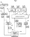
- a traveling work control section 4 inputs traveling data indicative of a state of the traveling mechanism 10, engine data indicative of a state of the engine 20, and work data indicative of a state of the implement 30.
- the traveling work control section 4 has a traveling control function for controlling operational devices of the traveling mechanism 10, an engine control function for controlling operational devices of the engine 20, and an implement control function for controlling operational devices of the implement 30.
- the work vehicle through controlling the engine 20 and the traveling mechanism 10, will control such that the implement 30 will effect a ground work while the vehicle is traveling at a constant speed (a target speed) (a constant vehicle speed such as 5 km/h, 10 km/h, etc.).
- a target speed a constant vehicle speed such as 5 km/h, 10 km/h, etc.
- a load ratio calculation section 53 calculates an engine load ratio.
- a slip ratio calculation section 52 calculates a slip ratio based on a target speed and a ground speed.
- the traveling work control section 4 controls the engine 20 and the implement 30 and also the traveling mechanism 10 when necessary.
- Various kinds of parameters for creating an appropriate traveling work state are set as default data. However, as these are realized under ideal conditions, some adjustment will be needed in an actual traveling work.
- a traveling work management section 50 outputs a state changing command for commanding a change in the traveling work state to the traveling work control section 4. And, this state changing command will be derived, based on an engine load ratio calculated by the load ratio calculation section 53 and a slip ratio calculated by the slip ratio calculation section 52.
- the state changing command comprises basically a command for the engine 20 and the implement 30, so this command includes a command for increasing/decreasing an engine rotational speed, a command for changing posture or position of the implement, in order to optimize engine load or work load.
- control rules are not limited thereto.
- the threshold values employed in the respective control rules can be numeral values obtained statistically in advance or numeral values derived by arithmetical operations from data groups contained in work histories of various work vehicles.
- the engine load ratio and the slip ratio can vary, either in dependence on each other or independently of each other. Further, increases of the engine load ratio and the slip ratio respectively invite reduction in the ground speed of the work vehicle. In other words, in the case of reduction in the ground speed, it will be possible to output an appropriate state changing command by estimating which one of engine load increase and slip increase contributes more to this ground speed reduction. Then, to this end, the traveling work management section 50 incorporates therein a contribution estimation section 501 for estimating a contribution ratio of the slip ratio and a contribution ratio of the engine load to the reduction in the ground speed and has a function of driving a state changing command from these contribution ratios.
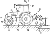
- the work vehicle as shown in Fig. 2 , is a tractor mounting the implement 30 such as a rotary cultivator for effecting an agricultural work, cultivation work etc., on a field (work site) delimited by ridges or the like.
- a maneuvering area is provided at a center portion of a vehicle body 1 which is supported by front wheels 11 and rear wheels 12 constituting the traveling mechanism 10.
- the traveling mechanism 10 includes also a transmission having a speed changer device, etc. in addition to the front wheels 11 and the rear wheels 12.
- the engine 20 At a front portion of the vehicle body, there is mounted the engine 20 for transmitting a rotational power to the traveling mechanism 10.
- the implement 30 which is a rotary cultivator, via a hydraulic lift mechanism 31.
- Rotational power of the rotary cultivator is fed by the engine 20. Therefore, the higher the traveling speed (ground speed) of the vehicle body 1 and the greater the depth of the cultivation by the rotary cultivator, the greater the load to be applied to the engine 20.
- the front wheels 11 function as steering wheels and by changing a steering angle thereof, a traveling direction of the tractor is changed.
- the steering angle of the front wheels 11 is changed by an operation of a steering mechanism 13.
- This steering mechanism 13 includes a steering motor 14 for automatic steering. At time of manual traveling, steering of the front wheels 11 can be made by operating a steering wheel 22.
- a satellite positioning module 80 constituted as a GNSS module.
- a satellite antenna for receiving GPS signals or GNSS signals is mounted to a ceiling area of the cabin 21.
- the satellite positioning module 80 can include an inertial navigation module incorporating a gyro acceleration sensor, a geomagnetic direction sensor etc., in order to assist the satellite navigation. Needless to say, the inertial navigation module can be provided at a site different from the satellite positioning module 80.
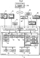
- FIG. 3 shows a control system built in this tractor.
- This control system employs the basic principle which was explained above with reference to Fig. 1 .
- a control unit 5 which is the core component of this control system includes an output processing section 7, an input processing section 8 and a communication processing section 70, which function as input/output interfaces.
- the output processing section 7 is connected to a vehicle traveling device group 71, an implement device group 72, an informing device 73, etc.
- the vehicle traveling device group 71 includes control devices relating to vehicle traveling, e.g. an engine controller, a speed change controller, a brake controller, a steering controller, etc.
- the implement device group 72 includes a driving mechanism for the implement 30 which is a rotary cultivator in the instant embodiment, a lift cylinder controller for the lift mechanism 31 for lifting up/down the rotary cultivator, etc.
- the communication processing section 70 has functions of transmitting data processed by the control unit 5 to a management computer 100 built at the remote management center and receiving various data from the management computer 100.
- the informing device 73 includes a flat display panel, a lamp, a buzzer and informs a driver or an operator of various kinds of information desired to be informed to the driver or operator in visual or audible form. Signal transmission between the informing device 73 and the output processing section 7 is effected in either wired or wireless manner.
- the input processing section 8 is connected to the satellite positioning module 80, a traveling system detection sensor group 81, an implement system detection sensor group 82, an automatic/manual switching operation tool 83, etc.
- the traveling system detection sensor group 81 includes sensors for detecting traveling states such as an engine rotational speed, a speed change state, and so on.
- the implement system detection sensor group 82 includes sensors for detecting a position or a tilting of the implement 30, a senor for detecting work load, etc.
- the automatic/manual switching operation tool 83 is a switch for selecting either an automatic traveling mode for traveling by automatic steering and a manual steering mode for traveling by the manual steering.
- the control unit 5 incorporate those functional sections described above with reference to Fig. 1 , namely, the traveling work control section 4, the ground speed calculation section 51, the slip ratio calculation section 52, the load ratio calculation section 53, the traveling work management section 50.
- the traveling work control section4 includes a traveling control section 41 for controlling operational devices of the traveling mechanism 10, the implement control section 42 for controlling operational device of the implement 30 and the engine control section 43 for controlling the operational devices of the engine 20.
- the traveling work control section 4 sets an engine rotational speed, a speed change position, posture of the implement 30 (cultivation depth), in order to create a target traveling work state from the implement 30 mounted on the vehicle body 1 and situation of the field, for realizing optimal work efficiency of the implement 30.
- the traveling work management section 50 will provide a state changing command based on an engine load ratio and/or a slip ratio to the traveling work control section 4 in order to change such current traveling work state.
- the ground speed calculation section 51 obtains a ground speed (actual vehicle speed) of the vehicle body 1, from self-vehicle positions calculated based on positioning data transmitted in sequence from the satellite positioning module 80 and periods required for traveling between two calculated self-vehicle positions.
- This slip ratio calculation section 52 calculates a slip ratio from an apparent vehicle speed calculated from an axle rotational speed of the rear wheels 12 and an actual vehicle speed calculated by the ground speed calculation section 51.
- a graph (a table) showing relationship between reduction amounts of engine rotational speed (engine drop amounts) from a reference rotational speed which is an engine rotation speed at time of zero load and torque changes is produced in advance for each accelerator opening degree. Then, based on this graph, an engine load ratio is calculated from a partial load degree which is calculated from a current engine rotational speed and a maximum load degree.
- the engine load ratio is defined simply as a value which becomes greater in correspondence with increase in the reduction amount of the engine rotational speed. Since such engine load ratio is used for engine control, in case the engine load ratio is handled by the engine control section 43, the load ratio calculation section 53 may employ this engine load ratio.
- the traveling work management section 50 will give a state changing command to the traveling work control section 4 in order to improve work efficiency, in case it has been determined that a traveling work state created by the traveling work control section 4 should be changed. For example, if the ground speed decreases during a constant-speed work implanting traveling, the cultivation pitch of the implement 30 will be too small under this state. So, the command can be provided for increase of the engine rotational speed, decrease of the cultivation depth, change of the speed, etc. Further, in case the ground speed is being kept constant and any reduction in the engine rotational speed is not occurring, either, this means that the work is currently being carried out in a favorable manner.
- the traveling work management section 50 can output a state changing command for e.g. further improving the work efficiency through small increase in the vehicle speed, or small increase in the cultivation depth, etc.
- the traveling work management section 50 in this embodiment incorporates the contribution estimation section 501 for estimating a contribution ratio of the slip ratio and a contribution ratio of the engine load to the reduction in the ground speed and has a function of determining contents of a state changing command in accordance with such contribution ratios.
- the traveling control section 41 includes a manual traveling control section 411 as well as an automatic traveling control section 412.
- the vehicle travels along a preset target traveling route, so there is provided a route setting section 61 for setting such target traveling route.
- Generation of the target traveling route is done by the control unit 5 and/or the management computer 100.
- this control unit 5 will be equipped with a route generation section 62 having a route generation algorithm.
- generated target traveling route will be sent from the management computer 100 to the control unit 5 and set by the route setting section 61.
- the automatic traveling control section 412 calculates any direction error and position error between the target traveling route and the self-vehicle position and generates an automatic steering instruction and outputs this to the steering motor 14 (see Fig. 2 ) included in the vehicle traveling device group 71 via the output processing section 7.
- Both the manual traveling control section 411 and the automatic traveling control section 412 together constituting the traveling control section 41 can provide a constant vehicle speed command to the traveling mechanism 10 for traveling at a constant vehicle speed.
- a constant speed vehicle traveling for traveling with automatically maintaining a constant vehicle speed (or, a different vehicle speed may be employed for straight traveling and turning traveling) is possible.
- the data inputted to the control unit 5 or the data generated in the control unit 5 will be recorded in the recording section 55, so that designated data in the recorded data will be forwarded to the management computer 100 by a real-time processing or a batch processing.
- the control unit 5 further includes an informing section 56.
- the informing section 56 In case various kinds of data handled by the control unit 5 exceed a predetermined allowable range or in case a state changing command is outputted by the traveling work management section 50, the informing section 56 generates informing data for informing its contents via the informing device 73.
- this determination process will be carried out continuously as long as vehicle speed reduction exceeding the threshold value is occurring.
- the traveling work management section 50 will generate a state changing command capable of changing the current work-implementing travel state appropriately, based on the inputted parameters (vehicle speed reduction amount, engine load ratio, slip ratio), and will give this state changing command to the traveling work control section 4.
- This state changing command includes small decrease/increase of engine rotational speed, small decrease/increase of cultivation depth, small decrease/increase of constant vehicle speed value, etc.
- a work implanting traveling state change was made, based on contribution ratios of engine load ratio and slip ratio relative to vehicle speed reduction. Instead, such change can be made based on a control rule using the above-described threshold values. Further alternatively, it is also possible to employ an arrangement of selecting between a work-implementing travel state change using contribution ratios and a work-implementing travel state change using a control rule or an arrangement using these in mixed state.
- the present invention is applicable to a work vehicle that effects a ground work while grasping a ground speed using satellite positioning data.
Landscapes
- Engineering & Computer Science (AREA)
- Life Sciences & Earth Sciences (AREA)
- Mechanical Engineering (AREA)
- Chemical & Material Sciences (AREA)
- Combustion & Propulsion (AREA)
- Soil Sciences (AREA)
- Environmental Sciences (AREA)
- Transportation (AREA)
- Lifting Devices For Agricultural Implements (AREA)
- Guiding Agricultural Machines (AREA)
Applications Claiming Priority (2)
| Application Number | Priority Date | Filing Date | Title |
|---|---|---|---|
| JP2016105364A JP6879677B2 (ja) | 2016-05-26 | 2016-05-26 | 作業車 |
| PCT/JP2016/086595 WO2017203734A1 (fr) | 2016-05-26 | 2016-12-08 | Engin de chantier |
Publications (3)
| Publication Number | Publication Date |
|---|---|
| EP3466231A1 true EP3466231A1 (fr) | 2019-04-10 |
| EP3466231A4 EP3466231A4 (fr) | 2020-01-15 |
| EP3466231B1 EP3466231B1 (fr) | 2022-04-27 |
Family
ID=60412198
Family Applications (1)
| Application Number | Title | Priority Date | Filing Date |
|---|---|---|---|
| EP16903213.3A Active EP3466231B1 (fr) | 2016-05-26 | 2016-12-08 | Engin de chantier |
Country Status (5)
| Country | Link |
|---|---|
| US (1) | US10813271B2 (fr) |
| EP (1) | EP3466231B1 (fr) |
| JP (1) | JP6879677B2 (fr) |
| CN (1) | CN108882677B (fr) |
| WO (1) | WO2017203734A1 (fr) |
Families Citing this family (10)
| Publication number | Priority date | Publication date | Assignee | Title |
|---|---|---|---|---|
| BR102017027139B1 (pt) * | 2017-12-15 | 2023-03-21 | José Roberto do Amaral Assy | Sistema de sensoriamento para implemento agrícola e método de sensoriamento de rotação aplicado em implemento agrícola |
| US10838432B2 (en) * | 2018-01-26 | 2020-11-17 | Cnh Industrial Canada, Ltd. | System and method for monitoring frame levelness of an agricultural implement |
| JP2020119379A (ja) * | 2019-01-25 | 2020-08-06 | 本田技研工業株式会社 | 管理装置、管理装置の制御方法及びプログラム |
| JP7192667B2 (ja) * | 2019-06-06 | 2022-12-20 | 井関農機株式会社 | 自律走行作業車 |
| US11528836B2 (en) | 2019-11-22 | 2022-12-20 | Cnh Industrial America Llc | System and method for sequentially controlling agricultural implement ground-engaging tools |
| US11511743B2 (en) * | 2019-12-17 | 2022-11-29 | Cnh Industrial Canada, Ltd. | System and method for controlling the speed of a work vehicle towing an implement |
| JP7410740B2 (ja) * | 2020-02-19 | 2024-01-10 | 株式会社Subaru | 制御装置 |
| US12250893B2 (en) * | 2021-06-15 | 2025-03-18 | Agtonomy | Powertrain system and management |
| CN116171711B (zh) * | 2023-03-30 | 2024-12-20 | 广东皓耘科技有限公司 | 负荷功率控制方法、装置及控制设备 |
| US20240393794A1 (en) * | 2023-05-23 | 2024-11-28 | Cnh Industrial America Llc | Advanced slip control for an agricultural vehicle |
Family Cites Families (11)
| Publication number | Priority date | Publication date | Assignee | Title |
|---|---|---|---|---|
| JPS5369108A (en) * | 1976-11-27 | 1978-06-20 | Kubota Ltd | Farm working machine for soil |
| GB2318651A (en) * | 1996-10-23 | 1998-04-29 | New Holland | Integrated vehicle control system |
| JP2000078905A (ja) | 1999-10-01 | 2000-03-21 | Yanmar Diesel Engine Co Ltd | トラクタの作業機制御機構 |
| GB0130673D0 (en) * | 2001-12-21 | 2002-02-06 | New Holland Uk Ltd | Tractor/implement combination control methods and apparatuses |
| JP4315248B2 (ja) * | 2004-12-13 | 2009-08-19 | 日立建機株式会社 | 走行作業車両の制御装置 |
| JP4634172B2 (ja) | 2005-02-09 | 2011-02-16 | ヤンマー株式会社 | スリップ防止システム |
| JO3126B1 (ar) | 2007-11-14 | 2017-09-20 | Janssen Pharmaceutica Nv | مثبطات ناقل نيوكليوسيد متوازن اي ان تي 1 |
| JP2009257181A (ja) * | 2008-04-16 | 2009-11-05 | Kubota Corp | 作業車 |
| JP5727822B2 (ja) * | 2011-03-15 | 2015-06-03 | 株式会社クボタ | トラクタ |
| JP5871612B2 (ja) * | 2011-12-26 | 2016-03-01 | 株式会社クボタ | 作業車 |
| JP5940960B2 (ja) | 2012-11-07 | 2016-06-29 | 株式会社クボタ | 作業車両の駆動制御機構 |
-
2016
- 2016-05-26 JP JP2016105364A patent/JP6879677B2/ja active Active
- 2016-12-08 EP EP16903213.3A patent/EP3466231B1/fr active Active
- 2016-12-08 CN CN201680084254.3A patent/CN108882677B/zh active Active
- 2016-12-08 US US16/089,680 patent/US10813271B2/en active Active
- 2016-12-08 WO PCT/JP2016/086595 patent/WO2017203734A1/fr not_active Ceased
Also Published As
| Publication number | Publication date |
|---|---|
| WO2017203734A1 (fr) | 2017-11-30 |
| JP2017209069A (ja) | 2017-11-30 |
| CN108882677B (zh) | 2021-12-17 |
| US20190104675A1 (en) | 2019-04-11 |
| EP3466231A4 (fr) | 2020-01-15 |
| CN108882677A (zh) | 2018-11-23 |
| JP6879677B2 (ja) | 2021-06-02 |
| EP3466231B1 (fr) | 2022-04-27 |
| US10813271B2 (en) | 2020-10-27 |
Similar Documents
| Publication | Publication Date | Title |
|---|---|---|
| EP3466231B1 (fr) | Engin de chantier | |
| US8838311B2 (en) | Vehicle having independently driven and controlled right and left drive wheels | |
| US9150104B2 (en) | Vehicle steering-based speed control system and method | |
| KR102277285B1 (ko) | 후륜 조향 제어 장치 및 방법 | |
| EP2942227A2 (fr) | Procédé et appareil de commande de traction destiné à un véhicule de travail à entraînements indépendants | |
| US20200086911A1 (en) | Machine steering angle control system | |
| KR102881929B1 (ko) | 차량의 자세 제어 방법 | |
| US9002593B2 (en) | System and method for re-directing a ripping path | |
| JP2020162282A (ja) | 作業車両 | |
| WO2010107000A1 (fr) | Véhicule de génie civil | |
| AU2019202430B2 (en) | System and method for controlling track slip of a machine | |
| JP6643190B2 (ja) | 作業車 | |
| JPS58123932A (ja) | 土工車輌のスリツプ自動補正装置 | |
| EP3704931B1 (fr) | Véhicule de déplacement | |
| WO2020090862A1 (fr) | Dispositif de commande d'angle de volant de direction | |
| JP2018041359A (ja) | 自律走行システム | |
| JP2020162281A (ja) | 作業車両 | |
| JP2018001807A (ja) | 作業車両 | |
| WO2021125095A1 (fr) | Machine de travail | |
| JP6919012B2 (ja) | 自律走行システム | |
| JP4107592B2 (ja) | 作業機のローリング制御装置 | |
| JP4107589B2 (ja) | 作業機のローリング制御装置 | |
| EP4691828A1 (fr) | Véhicule de transport électrique et système de commande de fonctionnement associé | |
| KR102959163B1 (ko) | 작업기 | |
| JP5118076B2 (ja) | 作業機のパルス信号出力構造 |
Legal Events
| Date | Code | Title | Description |
|---|---|---|---|
| STAA | Information on the status of an ep patent application or granted ep patent |
Free format text: STATUS: THE INTERNATIONAL PUBLICATION HAS BEEN MADE |
|
| PUAI | Public reference made under article 153(3) epc to a published international application that has entered the european phase |
Free format text: ORIGINAL CODE: 0009012 |
|
| STAA | Information on the status of an ep patent application or granted ep patent |
Free format text: STATUS: REQUEST FOR EXAMINATION WAS MADE |
|
| 17P | Request for examination filed |
Effective date: 20181004 |
|
| AK | Designated contracting states |
Kind code of ref document: A1 Designated state(s): AL AT BE BG CH CY CZ DE DK EE ES FI FR GB GR HR HU IE IS IT LI LT LU LV MC MK MT NL NO PL PT RO RS SE SI SK SM TR |
|
| AX | Request for extension of the european patent |
Extension state: BA ME |
|
| DAV | Request for validation of the european patent (deleted) | ||
| DAX | Request for extension of the european patent (deleted) | ||
| A4 | Supplementary search report drawn up and despatched |
Effective date: 20191217 |
|
| RIC1 | Information provided on ipc code assigned before grant |
Ipc: A01B 63/112 20060101AFI20191211BHEP |
|
| STAA | Information on the status of an ep patent application or granted ep patent |
Free format text: STATUS: EXAMINATION IS IN PROGRESS |
|
| 17Q | First examination report despatched |
Effective date: 20210401 |
|
| GRAP | Despatch of communication of intention to grant a patent |
Free format text: ORIGINAL CODE: EPIDOSNIGR1 |
|
| STAA | Information on the status of an ep patent application or granted ep patent |
Free format text: STATUS: GRANT OF PATENT IS INTENDED |
|
| INTG | Intention to grant announced |
Effective date: 20211122 |
|
| GRAS | Grant fee paid |
Free format text: ORIGINAL CODE: EPIDOSNIGR3 |
|
| GRAA | (expected) grant |
Free format text: ORIGINAL CODE: 0009210 |
|
| STAA | Information on the status of an ep patent application or granted ep patent |
Free format text: STATUS: THE PATENT HAS BEEN GRANTED |
|
| AK | Designated contracting states |
Kind code of ref document: B1 Designated state(s): AL AT BE BG CH CY CZ DE DK EE ES FI FR GB GR HR HU IE IS IT LI LT LU LV MC MK MT NL NO PL PT RO RS SE SI SK SM TR |
|
| REG | Reference to a national code |
Ref country code: GB Ref legal event code: FG4D |
|
| REG | Reference to a national code |
Ref country code: CH Ref legal event code: EP |
|
| REG | Reference to a national code |
Ref country code: AT Ref legal event code: REF Ref document number: 1486201 Country of ref document: AT Kind code of ref document: T Effective date: 20220515 |
|
| REG | Reference to a national code |
Ref country code: DE Ref legal event code: R096 Ref document number: 602016071615 Country of ref document: DE |
|
| REG | Reference to a national code |
Ref country code: IE Ref legal event code: FG4D |
|
| REG | Reference to a national code |
Ref country code: LT Ref legal event code: MG9D |
|
| REG | Reference to a national code |
Ref country code: NL Ref legal event code: MP Effective date: 20220427 |
|
| REG | Reference to a national code |
Ref country code: AT Ref legal event code: MK05 Ref document number: 1486201 Country of ref document: AT Kind code of ref document: T Effective date: 20220427 |
|
| PG25 | Lapsed in a contracting state [announced via postgrant information from national office to epo] |
Ref country code: NL Free format text: LAPSE BECAUSE OF FAILURE TO SUBMIT A TRANSLATION OF THE DESCRIPTION OR TO PAY THE FEE WITHIN THE PRESCRIBED TIME-LIMIT Effective date: 20220427 |
|
| PG25 | Lapsed in a contracting state [announced via postgrant information from national office to epo] |
Ref country code: SE Free format text: LAPSE BECAUSE OF FAILURE TO SUBMIT A TRANSLATION OF THE DESCRIPTION OR TO PAY THE FEE WITHIN THE PRESCRIBED TIME-LIMIT Effective date: 20220427 Ref country code: PT Free format text: LAPSE BECAUSE OF FAILURE TO SUBMIT A TRANSLATION OF THE DESCRIPTION OR TO PAY THE FEE WITHIN THE PRESCRIBED TIME-LIMIT Effective date: 20220829 Ref country code: NO Free format text: LAPSE BECAUSE OF FAILURE TO SUBMIT A TRANSLATION OF THE DESCRIPTION OR TO PAY THE FEE WITHIN THE PRESCRIBED TIME-LIMIT Effective date: 20220727 Ref country code: LT Free format text: LAPSE BECAUSE OF FAILURE TO SUBMIT A TRANSLATION OF THE DESCRIPTION OR TO PAY THE FEE WITHIN THE PRESCRIBED TIME-LIMIT Effective date: 20220427 Ref country code: HR Free format text: LAPSE BECAUSE OF FAILURE TO SUBMIT A TRANSLATION OF THE DESCRIPTION OR TO PAY THE FEE WITHIN THE PRESCRIBED TIME-LIMIT Effective date: 20220427 Ref country code: GR Free format text: LAPSE BECAUSE OF FAILURE TO SUBMIT A TRANSLATION OF THE DESCRIPTION OR TO PAY THE FEE WITHIN THE PRESCRIBED TIME-LIMIT Effective date: 20220728 Ref country code: FI Free format text: LAPSE BECAUSE OF FAILURE TO SUBMIT A TRANSLATION OF THE DESCRIPTION OR TO PAY THE FEE WITHIN THE PRESCRIBED TIME-LIMIT Effective date: 20220427 Ref country code: ES Free format text: LAPSE BECAUSE OF FAILURE TO SUBMIT A TRANSLATION OF THE DESCRIPTION OR TO PAY THE FEE WITHIN THE PRESCRIBED TIME-LIMIT Effective date: 20220427 Ref country code: BG Free format text: LAPSE BECAUSE OF FAILURE TO SUBMIT A TRANSLATION OF THE DESCRIPTION OR TO PAY THE FEE WITHIN THE PRESCRIBED TIME-LIMIT Effective date: 20220727 Ref country code: AT Free format text: LAPSE BECAUSE OF FAILURE TO SUBMIT A TRANSLATION OF THE DESCRIPTION OR TO PAY THE FEE WITHIN THE PRESCRIBED TIME-LIMIT Effective date: 20220427 |
|
| PG25 | Lapsed in a contracting state [announced via postgrant information from national office to epo] |
Ref country code: RS Free format text: LAPSE BECAUSE OF FAILURE TO SUBMIT A TRANSLATION OF THE DESCRIPTION OR TO PAY THE FEE WITHIN THE PRESCRIBED TIME-LIMIT Effective date: 20220427 Ref country code: PL Free format text: LAPSE BECAUSE OF FAILURE TO SUBMIT A TRANSLATION OF THE DESCRIPTION OR TO PAY THE FEE WITHIN THE PRESCRIBED TIME-LIMIT Effective date: 20220427 Ref country code: LV Free format text: LAPSE BECAUSE OF FAILURE TO SUBMIT A TRANSLATION OF THE DESCRIPTION OR TO PAY THE FEE WITHIN THE PRESCRIBED TIME-LIMIT Effective date: 20220427 Ref country code: IS Free format text: LAPSE BECAUSE OF FAILURE TO SUBMIT A TRANSLATION OF THE DESCRIPTION OR TO PAY THE FEE WITHIN THE PRESCRIBED TIME-LIMIT Effective date: 20220827 |
|
| REG | Reference to a national code |
Ref country code: DE Ref legal event code: R097 Ref document number: 602016071615 Country of ref document: DE |
|
| PG25 | Lapsed in a contracting state [announced via postgrant information from national office to epo] |
Ref country code: SM Free format text: LAPSE BECAUSE OF FAILURE TO SUBMIT A TRANSLATION OF THE DESCRIPTION OR TO PAY THE FEE WITHIN THE PRESCRIBED TIME-LIMIT Effective date: 20220427 Ref country code: SK Free format text: LAPSE BECAUSE OF FAILURE TO SUBMIT A TRANSLATION OF THE DESCRIPTION OR TO PAY THE FEE WITHIN THE PRESCRIBED TIME-LIMIT Effective date: 20220427 Ref country code: RO Free format text: LAPSE BECAUSE OF FAILURE TO SUBMIT A TRANSLATION OF THE DESCRIPTION OR TO PAY THE FEE WITHIN THE PRESCRIBED TIME-LIMIT Effective date: 20220427 Ref country code: EE Free format text: LAPSE BECAUSE OF FAILURE TO SUBMIT A TRANSLATION OF THE DESCRIPTION OR TO PAY THE FEE WITHIN THE PRESCRIBED TIME-LIMIT Effective date: 20220427 Ref country code: DK Free format text: LAPSE BECAUSE OF FAILURE TO SUBMIT A TRANSLATION OF THE DESCRIPTION OR TO PAY THE FEE WITHIN THE PRESCRIBED TIME-LIMIT Effective date: 20220427 Ref country code: CZ Free format text: LAPSE BECAUSE OF FAILURE TO SUBMIT A TRANSLATION OF THE DESCRIPTION OR TO PAY THE FEE WITHIN THE PRESCRIBED TIME-LIMIT Effective date: 20220427 |
|
| PLBE | No opposition filed within time limit |
Free format text: ORIGINAL CODE: 0009261 |
|
| STAA | Information on the status of an ep patent application or granted ep patent |
Free format text: STATUS: NO OPPOSITION FILED WITHIN TIME LIMIT |
|
| REG | Reference to a national code |
Ref country code: DE Ref legal event code: R082 Ref document number: 602016071615 Country of ref document: DE Representative=s name: CBDL PATENTANWAELTE GBR, DE Ref country code: DE Ref legal event code: R082 Ref document number: 602016071615 Country of ref document: DE Representative=s name: CBDL PATENTANWAELTE EGBR, DE |
|
| PG25 | Lapsed in a contracting state [announced via postgrant information from national office to epo] |
Ref country code: AL Free format text: LAPSE BECAUSE OF FAILURE TO SUBMIT A TRANSLATION OF THE DESCRIPTION OR TO PAY THE FEE WITHIN THE PRESCRIBED TIME-LIMIT Effective date: 20220427 |
|
| 26N | No opposition filed |
Effective date: 20230130 |
|
| PG25 | Lapsed in a contracting state [announced via postgrant information from national office to epo] |
Ref country code: SI Free format text: LAPSE BECAUSE OF FAILURE TO SUBMIT A TRANSLATION OF THE DESCRIPTION OR TO PAY THE FEE WITHIN THE PRESCRIBED TIME-LIMIT Effective date: 20220427 |
|
| REG | Reference to a national code |
Ref country code: CH Ref legal event code: PL |
|
| GBPC | Gb: european patent ceased through non-payment of renewal fee |
Effective date: 20221208 |
|
| REG | Reference to a national code |
Ref country code: BE Ref legal event code: MM Effective date: 20221231 |
|
| PG25 | Lapsed in a contracting state [announced via postgrant information from national office to epo] |
Ref country code: LU Free format text: LAPSE BECAUSE OF NON-PAYMENT OF DUE FEES Effective date: 20221208 |
|
| PG25 | Lapsed in a contracting state [announced via postgrant information from national office to epo] |
Ref country code: LI Free format text: LAPSE BECAUSE OF NON-PAYMENT OF DUE FEES Effective date: 20221231 Ref country code: IE Free format text: LAPSE BECAUSE OF NON-PAYMENT OF DUE FEES Effective date: 20221208 Ref country code: GB Free format text: LAPSE BECAUSE OF NON-PAYMENT OF DUE FEES Effective date: 20221208 Ref country code: CH Free format text: LAPSE BECAUSE OF NON-PAYMENT OF DUE FEES Effective date: 20221231 |
|
| PG25 | Lapsed in a contracting state [announced via postgrant information from national office to epo] |
Ref country code: BE Free format text: LAPSE BECAUSE OF NON-PAYMENT OF DUE FEES Effective date: 20221231 |
|
| PG25 | Lapsed in a contracting state [announced via postgrant information from national office to epo] |
Ref country code: IT Free format text: LAPSE BECAUSE OF FAILURE TO SUBMIT A TRANSLATION OF THE DESCRIPTION OR TO PAY THE FEE WITHIN THE PRESCRIBED TIME-LIMIT Effective date: 20220427 |
|
| PG25 | Lapsed in a contracting state [announced via postgrant information from national office to epo] |
Ref country code: HU Free format text: LAPSE BECAUSE OF FAILURE TO SUBMIT A TRANSLATION OF THE DESCRIPTION OR TO PAY THE FEE WITHIN THE PRESCRIBED TIME-LIMIT; INVALID AB INITIO Effective date: 20161208 |
|
| PG25 | Lapsed in a contracting state [announced via postgrant information from national office to epo] |
Ref country code: CY Free format text: LAPSE BECAUSE OF FAILURE TO SUBMIT A TRANSLATION OF THE DESCRIPTION OR TO PAY THE FEE WITHIN THE PRESCRIBED TIME-LIMIT Effective date: 20220427 |
|
| PG25 | Lapsed in a contracting state [announced via postgrant information from national office to epo] |
Ref country code: MK Free format text: LAPSE BECAUSE OF FAILURE TO SUBMIT A TRANSLATION OF THE DESCRIPTION OR TO PAY THE FEE WITHIN THE PRESCRIBED TIME-LIMIT Effective date: 20220427 |
|
| PG25 | Lapsed in a contracting state [announced via postgrant information from national office to epo] |
Ref country code: MC Free format text: LAPSE BECAUSE OF FAILURE TO SUBMIT A TRANSLATION OF THE DESCRIPTION OR TO PAY THE FEE WITHIN THE PRESCRIBED TIME-LIMIT Effective date: 20220427 |
|
| PG25 | Lapsed in a contracting state [announced via postgrant information from national office to epo] |
Ref country code: MC Free format text: LAPSE BECAUSE OF FAILURE TO SUBMIT A TRANSLATION OF THE DESCRIPTION OR TO PAY THE FEE WITHIN THE PRESCRIBED TIME-LIMIT Effective date: 20220427 |
|
| PG25 | Lapsed in a contracting state [announced via postgrant information from national office to epo] |
Ref country code: MT Free format text: LAPSE BECAUSE OF FAILURE TO SUBMIT A TRANSLATION OF THE DESCRIPTION OR TO PAY THE FEE WITHIN THE PRESCRIBED TIME-LIMIT Effective date: 20220427 |
|
| PG25 | Lapsed in a contracting state [announced via postgrant information from national office to epo] |
Ref country code: BG Free format text: LAPSE BECAUSE OF FAILURE TO SUBMIT A TRANSLATION OF THE DESCRIPTION OR TO PAY THE FEE WITHIN THE PRESCRIBED TIME-LIMIT Effective date: 20220427 |
|
| PG25 | Lapsed in a contracting state [announced via postgrant information from national office to epo] |
Ref country code: BG Free format text: LAPSE BECAUSE OF FAILURE TO SUBMIT A TRANSLATION OF THE DESCRIPTION OR TO PAY THE FEE WITHIN THE PRESCRIBED TIME-LIMIT Effective date: 20220427 |
|
| PG25 | Lapsed in a contracting state [announced via postgrant information from national office to epo] |
Ref country code: TR Free format text: LAPSE BECAUSE OF FAILURE TO SUBMIT A TRANSLATION OF THE DESCRIPTION OR TO PAY THE FEE WITHIN THE PRESCRIBED TIME-LIMIT Effective date: 20220427 |
|
| PGFP | Annual fee paid to national office [announced via postgrant information from national office to epo] |
Ref country code: DE Payment date: 20251028 Year of fee payment: 10 |
|
| PGFP | Annual fee paid to national office [announced via postgrant information from national office to epo] |
Ref country code: FR Payment date: 20251110 Year of fee payment: 10 |