EP3466558B1 - Dispositif pour réduire le poids de vilebrequins - Google Patents
Dispositif pour réduire le poids de vilebrequins Download PDFInfo
- Publication number
- EP3466558B1 EP3466558B1 EP16903010.3A EP16903010A EP3466558B1 EP 3466558 B1 EP3466558 B1 EP 3466558B1 EP 16903010 A EP16903010 A EP 16903010A EP 3466558 B1 EP3466558 B1 EP 3466558B1
- Authority
- EP
- European Patent Office
- Prior art keywords
- weight
- moveable
- lightening
- calibrating
- bodies
- Prior art date
- Legal status (The legal status is an assumption and is not a legal conclusion. Google has not performed a legal analysis and makes no representation as to the accuracy of the status listed.)
- Active
Links
Images


Classifications
-
- B—PERFORMING OPERATIONS; TRANSPORTING
- B21—MECHANICAL METAL-WORKING WITHOUT ESSENTIALLY REMOVING MATERIAL; PUNCHING METAL
- B21J—FORGING; HAMMERING; PRESSING METAL; RIVETING; FORGE FURNACES
- B21J5/00—Methods for forging, hammering, or pressing; Special equipment or accessories therefor
- B21J5/02—Die forging; Trimming by making use of special dies ; Punching during forging
-
- B—PERFORMING OPERATIONS; TRANSPORTING
- B21—MECHANICAL METAL-WORKING WITHOUT ESSENTIALLY REMOVING MATERIAL; PUNCHING METAL
- B21K—MAKING FORGED OR PRESSED METAL PRODUCTS, e.g. HORSE-SHOES, RIVETS, BOLTS OR WHEELS
- B21K1/00—Making machine elements
- B21K1/06—Making machine elements axles or shafts
- B21K1/08—Making machine elements axles or shafts crankshafts
-
- B—PERFORMING OPERATIONS; TRANSPORTING
- B21—MECHANICAL METAL-WORKING WITHOUT ESSENTIALLY REMOVING MATERIAL; PUNCHING METAL
- B21J—FORGING; HAMMERING; PRESSING METAL; RIVETING; FORGE FURNACES
- B21J13/00—Details of machines for forging, pressing, or hammering
- B21J13/02—Dies or mountings therefor
- B21J13/025—Dies with parts moving along auxiliary lateral directions
-
- F—MECHANICAL ENGINEERING; LIGHTING; HEATING; WEAPONS; BLASTING
- F16—ENGINEERING ELEMENTS AND UNITS; GENERAL MEASURES FOR PRODUCING AND MAINTAINING EFFECTIVE FUNCTIONING OF MACHINES OR INSTALLATIONS; THERMAL INSULATION IN GENERAL
- F16C—SHAFTS; FLEXIBLE SHAFTS; ELEMENTS OR CRANKSHAFT MECHANISMS; ROTARY BODIES OTHER THAN GEARING ELEMENTS; BEARINGS
- F16C2220/00—Shaping
- F16C2220/40—Shaping by deformation without removing material
-
- F—MECHANICAL ENGINEERING; LIGHTING; HEATING; WEAPONS; BLASTING
- F16—ENGINEERING ELEMENTS AND UNITS; GENERAL MEASURES FOR PRODUCING AND MAINTAINING EFFECTIVE FUNCTIONING OF MACHINES OR INSTALLATIONS; THERMAL INSULATION IN GENERAL
- F16C—SHAFTS; FLEXIBLE SHAFTS; ELEMENTS OR CRANKSHAFT MECHANISMS; ROTARY BODIES OTHER THAN GEARING ELEMENTS; BEARINGS
- F16C3/00—Shafts; Axles; Cranks; Eccentrics
- F16C3/04—Crankshafts, eccentric-shafts; Cranks, eccentrics
- F16C3/06—Crankshafts
- F16C3/08—Crankshafts made in one piece
Definitions
- the present invention relates to a device for calibrating and lightening the weight of crankshafts of a motor of a vehicle.
- the key factor to facing this challenge is reducing weight: the smaller the vehicle, the less power required to accelerate it, and less energy required to maintain a constant speed, in addition to lower costs on raw material for the manufacturer.
- crankshafts highly influence the performance of the motor, since they are the component that is responsible for generating power, and therefore their weight/resistance relationship is essential.
- forging is considered the most suitable process for manufacturing crankshafts. Stamping at high forging temperatures is generally the process that leads to the best results. This process is able to produce high quality components at a reasonable cost. Forging provides a high degree of resistance in relation to weight, tenacity and fatigue strength, and resistance to impact, which are all important aspects in the design of crankshafts and for the performance thereof.
- the forging process it is first necessary to size the billet of material to be forged. To size the billet, it is necessary to define the load factor which corresponds to a coefficient, by which the volume of the piece must be multiplied to prevent material loss on the burr. Once this factor has been determined, a pre-dimensioning of the billet is done.
- a procedure for manufacturing a crankshaft is known from the document US 2014/0318310 A1 . This document describes a procedure for lightening the weight of crankshafts during the forging process without producing a degradation in the resistance of the crankshaft.
- the case mentioned in this document consists of a crankshaft with a cavity formed in each module of the crankshaft on the side on which the crankpins are located. These cavities are formed by a series of moveable bodies that penetrate the seat of the tooling during a forming process by forging. This is due the fact that this part is usually chamfered and, as such, the access of the moveable bodies that produce the cavities is easier than on a plane that is perpendicular to the rotating shaft of the crankshaft.
- this is one of the areas of the piece with a greater accumulation of material, since eliminating material there will have a smaller impact on the rigidity of the piece than in the other areas of the same, in which the rigidity would be degraded to a larger extent.
- the procedure described in this document analyzes the problem for a flat-plane crankshaft with 4 cylinders and 8 counterweights.
- the moveable bodies take advantage of the inclination of the outer areas of the chamfers in which the crankpins are located to penetrate the piece in a practically perpendicular way, which in another area of the crankshaft would be impossible to problems of space in the tooling.
- This document proposes a solution in which there are two types of cavities in the crankshaft. The first has a greater contact area and smaller penetration depth in the crankshaft, while the second is the opposite case, the contact surface is smaller with greater depth in the crankshaft.
- the two moveable bodies that penetrate the crankshaft in each crankpin have the same inclination with respect to the median plane of the cross section of the crankpin.
- Two chamfers are joined by the corresponding crankpin thereof before the moveable bodies penetrate the piece to form the cavities.
- the two chamfers go from being at a distance A (equal to the length of the crankpin) to being at a practically non-existent distance B, which, without considering structural problems, would prevent the correct rotation and functioning of the crankshaft.
- the object of the present invention is to provide a procedure and a device to calibrate and lighten the weight of automotive components with a greater productivity than with the procedures and devices currently known.
- the device for calibrating and lightening the weight of crankshaft according to the present invention is defined in claim 1.
- At least one, or all of the moveable bodies comprise a lowered portion close to said end that forms the cavity to lighten the weight, said lowered portion defining a projecting portion at said end, said projecting portion being that which forms said cavity, the bodies moving diagonally with respect to the seat of the tooling.
- said projecting portion and said lowered portion have rounded edges.
- said projecting portion can have a substantially semicircular form in a plan view, or said projecting portion can have a substantially rectangular form with the smaller sides thereof curved in a plan view, based on the type of moveable body.
- one type of moveable bodies which are mounted on said intermediate piece, comprise bevels, said moveable bodies substantially in contact with each other by means of these bevels, and furthermore, the bevel of each moveable body is arranged on the end provided with said projecting portion.
- said tooling comprises a lower edge piece in which the moveable bodies are mounted and an upper edge piece, said upper edge piece being moveable with respect to said lower edge piece and the assembly of said lower and upper edge pieces being moveable with respect to a frame of the device.
- said wedges are advantageously mounted in a fixed way to the frame of the device, such that the movement of the assembly of said lower and upper edge pieces causes the movement of the moveable bodies from the initial position to the final position thereof.
- each moveable body is advantageously associated with a spring, which presses the moveable body back to its initial position.
- a component for vehicles with a lighter weight is achieved, the calibrating and lightening of the weight being achieved in a more simple and productive way than in currently known systems.
- crankshaft it is advantageous to remove material on the contiguous chamfers of each crankpin. This is because they are areas that do not experience significant stresses and do not have any specific function.
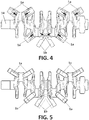
- the device according to the present invention comprises a tooling 10, formed by a lower edge piece 12 and an upper edge piece (not shown in the figures), as will be described further on.
- Said tooling 10 defines a seat 11 in the shape of the component that will be manufactured, such as a crankshaft 14.
- the device for forming the cavities in the component, the device according to the present invention comprises a plurality of moveable bodies 1a, 1b, which can move from an initial position ( figure 4 ) in which said moveable bodies 1a, 1b are outside of said seat 11, to a final position ( figure 5 ), in which one of the two ends of each moveable body 1a, 1b is on the inside of the seat 11 to form said cavities when the component is manufactured 14.
- the component 14 has two types of chamfers.
- the device according to the present invention will comprise two types of moveable bodies, respectively identified by the references 1a and 1b, in other words, first moveable bodies 1a and second moveable bodies 1b.
- Said first moveable bodies 1a can move longitudinally along the longitudinal axis thereof and said second moveable bodies 1b can move laterally, in other words, perpendicular with respect to the longitudinal axis thereof.
- Figures 2 and 3 show a first moveable body 1a and a second moveable body 1b, respectively.
- the moveable body 1a, 1b comprises a lowered portion 2 close to one end of the body.
- This lowered position 2 defines a projecting portion 3, which forms the cavity in the component 14.
- said projecting portion 3 has a substantially rectangular plan form with the smaller sides thereof curved, while in the case of the second moveable body 1b, the projecting portion 3 has a substantially semicircular plan form. Moreover, in both cases the edges are rounded to prevent sharp edges.
- first moveable bodies 1a In the case that the first moveable bodies 1a, the same are placed just as shown in the figures.
- the first moveable bodies 1a are mounted on wedges 4 for diagonal movement of the first moveable bodies 1a, as will be described below.
- the first moveable bodies 1a comprise an inclined surface 6 that is in contact with the wedge 4.
- two second moveable bodies 1b are placed in a centered position as shown in the figures. These second moveable bodies 1b are mounted on an intermediate piece 5, which, in turn is mounted on a wedge 4. In the initial position ( figure 4 ) said second moveable bodies 1b are substantially in contact with one another by means of a bevel 7, while in the final position ( figure 5 ) they are separated.
- the mounting of the device according to the present invention is done in the following way. Firstly, a lower edge piece 12 is mounted for calibration.
- springs 15 are mounted which return the moveable bodies 1a, 1b to their initial positions. Then, the moveable bodies 1a, 1b and the intermediate piece 5 are mounted in their positions.
- the calibration process which is done by means of the device according to the present invention, is the last operation in the manufacturing process of the crankshaft. It must be stated that before the calibration process, during which the weight of the crankshaft is calibrated and lightened, other stages are performed, which are not described in the present invention because they are evident for a person skilled in the art and do not form part of the present invention.
- the process of calibrating and lightening the weight of the components is the following.
- the upper edge piece lowers until making contact with the lower edge piece 12 (which until this moment was immobile) and closes the device, enclosing the component 14. At this point, both edge pieces move downward in an integral way as a single block.
- the lower edge piece 12 has the moveable bodies secured to the same by the springs, moveable bodies which penetrate the aforementioned crankshaft chamfers, forming the cavities.
- the movement of these moveable bodies can be divided into two parts:
- the cylinders make the assembly of the edge pieces return to the initial position thereof.
- the springs 15 that secure the moveable bodies 1a, 1b also return them to their initial position.
Landscapes
- Engineering & Computer Science (AREA)
- Mechanical Engineering (AREA)
- General Engineering & Computer Science (AREA)
- Ocean & Marine Engineering (AREA)
- Shafts, Cranks, Connecting Bars, And Related Bearings (AREA)
- Forging (AREA)
- Bearings For Parts Moving Linearly (AREA)
Claims (12)
- Dispositif pour calibrer et alléger le poids de vilebrequins, qui comprend un outillage (10) muni d'un siège (11) pour le vilebrequin ; une pluralité de corps déplaçables (1a, 1b), déplaçables entre une position initiale et une position finale, de sorte que dans la position finale une extrémité de chaque dit corps déplaçable (1a, 1b) pénètre le siège (11) pour former une cavité afin d'alléger le poids du vilebrequin ; et des coins (4), sur lesquels les corps déplaçables (1a, 1b) sont montés, munis d'un plan incliné pour déplacer les corps (1a, 1b) vis-à-vis du siège (11) de l'outillage (10), caractérisé en ce que deux desdits corps (1b) sont montés sur une pièce intermédiaire (5) qui, elle, est montée sur l'un desdits coins (4) de sorte que lesdits corps déplaçables (1b) soient déplaçables latéralement par rapport à leur axe longitudinal respectif.
- Dispositif pour calibrer et alléger le poids de vilebrequins selon la revendication 1, dans lequel au moins l'un ou l'ensemble des corps déplaçables (1a, 1b) comprennent une portion abaissée (2) proche de ladite extrémité qui forme la cavité pour alléger le poids, ladite portion abaissée (2) définissant une portion saillante (3) à ladite extrémité, ladite portion saillante (3) étant celle qui forme ladite cavité.
- Dispositif pour calibrer et alléger le poids de vilebrequins selon la revendication 1, dans lequel au moins l'un ou l'ensemble des corps déplaçables (1a) comprennent une surface inclinée (6) complémentaire du plan incliné desdits coins (4).
- Dispositif pour calibrer et alléger le poids de vilebrequins selon la revendication 2, dans lequel ladite portion saillante (3) a des bords arrondis.
- Dispositif pour calibrer et alléger le poids de vilebrequins selon la revendication 2, dans lequel ladite portion abaissée (2) a des bords arrondis.
- Dispositif pour calibrer et alléger le poids de vilebrequins selon la revendication 2, dans lequel ladite portion saillante (3) a une forme sensiblement semi-circulaire en vue en plan.
- Dispositif pour calibrer et alléger le poids de vilebrequins selon la revendication 2, dans lequel ladite portion saillante (3) a une forme sensiblement rectangulaire avec ses plus petits côtés courbés en vue en plan.
- Dispositif pour calibrer et alléger le poids de vilebrequins selon la revendication 1, dans lequel les corps déplaçables (1b) montés sur ladite pièce intermédiaire (5) comprennent des biseaux (7), lesdits corps déplaçables (1b) étant sensiblement en contact l'un avec l'autre au moyen de ces biseaux (7).
- Dispositif pour calibrer et alléger le poids de vilebrequins selon la revendication 8, dans lequel le biseau (7) est agencé sur l'extrémité munie de ladite portion saillante (3).
- Dispositif pour calibrer et alléger le poids de vilebrequins selon la revendication 1, dans lequel ledit outillage (10) comprend une pièce de bord inférieur (12) dans laquelle les corps déplaçables (1a, 1b) sont montés, et une pièce de bord supérieur, ladite pièce de bord supérieur étant déplaçable vis-à-vis de ladite pièce de bord inférieur (12) et l'assemblage desdites pièces de bords inférieur (12) et supérieur étant déplaçable vis-à-vis d'un bâti (16) du dispositif.
- Dispositif pour calibrer et alléger le poids de vilebrequins selon les revendications 1 et 10, dans lequel lesdits coins (4) sont avantageusement montés de manière fixe sur le bâti (16) du dispositif, de sorte que le déplacement de l'assemblage desdites pièces de bords inférieur (12) et supérieur entraîne le déplacement des corps déplaçables (1a, 1b) de leur position initiale à leur position finale.
- Dispositif pour calibrer et alléger le poids de vilebrequins selon la revendication 1, dans lequel chaque corps déplaçable (1a, 1b) est associé à un ressort (15) qui appuie sur le corps déplaçable (1a, 1b) pour le renvoyer à sa position initiale.
Applications Claiming Priority (1)
| Application Number | Priority Date | Filing Date | Title |
|---|---|---|---|
| PCT/ES2016/070391 WO2017203066A1 (fr) | 2016-05-24 | 2016-05-24 | Dispositif pour réduire le poids de composants de véhicules |
Publications (3)
| Publication Number | Publication Date |
|---|---|
| EP3466558A1 EP3466558A1 (fr) | 2019-04-10 |
| EP3466558A4 EP3466558A4 (fr) | 2020-01-08 |
| EP3466558B1 true EP3466558B1 (fr) | 2021-04-07 |
Family
ID=60412653
Family Applications (1)
| Application Number | Title | Priority Date | Filing Date |
|---|---|---|---|
| EP16903010.3A Active EP3466558B1 (fr) | 2016-05-24 | 2016-05-24 | Dispositif pour réduire le poids de vilebrequins |
Country Status (5)
| Country | Link |
|---|---|
| US (1) | US11311929B2 (fr) |
| EP (1) | EP3466558B1 (fr) |
| BR (1) | BR112018013918B1 (fr) |
| ES (1) | ES2879898T3 (fr) |
| WO (1) | WO2017203066A1 (fr) |
Families Citing this family (2)
| Publication number | Priority date | Publication date | Assignee | Title |
|---|---|---|---|---|
| JP7385131B2 (ja) * | 2020-04-03 | 2023-11-22 | 日本製鉄株式会社 | クランク軸の製造方法 |
| JP7385132B2 (ja) * | 2020-04-03 | 2023-11-22 | 日本製鉄株式会社 | クランク軸の製造方法 |
Family Cites Families (12)
| Publication number | Priority date | Publication date | Assignee | Title |
|---|---|---|---|---|
| US1932584A (en) * | 1933-01-19 | 1933-10-31 | Continental Can Co | Mandrel for can shaping machines |
| DE2754443A1 (de) * | 1977-12-07 | 1979-06-13 | Hahn Hermann Dr Ing | Verfahren zum herstellen von zylindrischen hohlkoerpern und vorrichtung zur durchfuehrung dieses verfahrens |
| JPS58199637A (ja) * | 1982-05-18 | 1983-11-21 | Kayaba Ind Co Ltd | ロータリバルブの加工方法 |
| WO2010090284A1 (fr) * | 2009-02-09 | 2010-08-12 | 本田技研工業株式会社 | Procédé et appareil pour produire un arbre de vilebrequin |
| EP2412993B1 (fr) | 2009-03-26 | 2014-12-31 | Honda Motor Co., Ltd. | Vilebrequin et son procédé de fabrication |
| JP5324284B2 (ja) * | 2009-03-27 | 2013-10-23 | 本田技研工業株式会社 | クランクシャフトの製造装置および製造方法 |
| EP2546006B1 (fr) * | 2010-03-31 | 2023-06-28 | NSK Ltd. | Procédé de fabrication d'un écrou de vis à billes |
| DE202012100361U1 (de) * | 2012-02-03 | 2013-05-06 | Rehau Ag + Co. | Expansionskopf für Aufweitwerkzeuge und diesen umfassendes Expansionswerkzeug |
| CN104884185B (zh) * | 2012-12-12 | 2016-11-02 | 新日铁住金株式会社 | 三汽缸发动机用锻造曲轴的精锻用坯料的成形装置及制造三汽缸发动机用锻造曲轴的方法 |
| WO2016009620A1 (fr) * | 2014-07-14 | 2016-01-21 | 新日鐵住金株式会社 | Procédé de fabrication de vilebrequin coulé |
| CN107530764B (zh) * | 2015-05-14 | 2019-05-31 | 新日铁住金株式会社 | 锻造曲轴的制造装置 |
| JP2017094341A (ja) * | 2015-11-18 | 2017-06-01 | 株式会社神戸製鋼所 | プレス成形品の製造方法及びプレス成形装置 |
-
2016
- 2016-05-24 US US16/303,978 patent/US11311929B2/en active Active
- 2016-05-24 WO PCT/ES2016/070391 patent/WO2017203066A1/fr not_active Ceased
- 2016-05-24 EP EP16903010.3A patent/EP3466558B1/fr active Active
- 2016-05-24 BR BR112018013918-1A patent/BR112018013918B1/pt active IP Right Grant
- 2016-05-24 ES ES16903010T patent/ES2879898T3/es active Active
Also Published As
| Publication number | Publication date |
|---|---|
| BR112018013918A2 (pt) | 2018-12-11 |
| US20200038939A1 (en) | 2020-02-06 |
| EP3466558A4 (fr) | 2020-01-08 |
| EP3466558A1 (fr) | 2019-04-10 |
| WO2017203066A1 (fr) | 2017-11-30 |
| US11311929B2 (en) | 2022-04-26 |
| ES2879898T3 (es) | 2021-11-23 |
| BR112018013918B1 (pt) | 2021-10-13 |
Similar Documents
| Publication | Publication Date | Title |
|---|---|---|
| JP5800091B2 (ja) | 型鍛造クランク軸の製造方法 | |
| CN104942213B (zh) | 用于内燃机的活塞及其制造方法 | |
| CN101959627A (zh) | 金属锻造的曲轴、用于金属锻造曲轴的设备以及金属锻造曲轴的方法 | |
| JP2010230027A (ja) | クランクシャフトおよびその製造方法 | |
| WO2010090284A1 (fr) | Procédé et appareil pour produire un arbre de vilebrequin | |
| JP2012007726A (ja) | クランクシャフトおよびその製造方法 | |
| EP3466558B1 (fr) | Dispositif pour réduire le poids de vilebrequins | |
| CN108506457A (zh) | 用于平衡轴的齿轮以及平衡轴 | |
| US20140202001A1 (en) | Method for the production of a piston for an internal combustion engine | |
| US10151340B2 (en) | High-contrast engine connecting rod | |
| JP2015500744A (ja) | 鍛造部品を製造する方法 | |
| JP5436331B2 (ja) | クランクシャフトの製造方法 | |
| KR101049918B1 (ko) | 캠와셔 일체형 캠볼트의 제조방법 | |
| KR102239914B1 (ko) | 자동차 엔진용 하우징 리프트 제조방법 | |
| US20150246393A1 (en) | Method of manufacturing connecting rod by using semi-closed sinter forging | |
| KR20060117358A (ko) | 하이드로 폼 성형품, 하이드로 폼 가공 방법 및 그에이용되는 금형 | |
| US20160025219A1 (en) | Machining Process for Trapezoid Rings With Small Axial Dimensions, Used in Pistons of Internal Combustion Engines | |
| KR100834112B1 (ko) | 차량의 인서트형 조립부싱 제조방법과 제조장치 | |
| KR101597172B1 (ko) | 디프렌셜 케이스의 제조방법 | |
| CN110395073B (zh) | 一件式半轴及其制造方法 | |
| US7065852B2 (en) | Method of manufacturing hydraulic shock absorber and production system for shock absorber in plant | |
| US11821398B2 (en) | Component for an injection system, in particular fuel distributor rail, injection system and method for producing such a component | |
| JP2015117428A (ja) | 部分焼入れ品の製造方法 | |
| JP2011012647A (ja) | シリンダブロックの加工方法及びシリンダブロック | |
| JP2010179350A (ja) | クランクシャフトの製造方法 |
Legal Events
| Date | Code | Title | Description |
|---|---|---|---|
| STAA | Information on the status of an ep patent application or granted ep patent |
Free format text: STATUS: THE INTERNATIONAL PUBLICATION HAS BEEN MADE |
|
| PUAI | Public reference made under article 153(3) epc to a published international application that has entered the european phase |
Free format text: ORIGINAL CODE: 0009012 |
|
| STAA | Information on the status of an ep patent application or granted ep patent |
Free format text: STATUS: REQUEST FOR EXAMINATION WAS MADE |
|
| 17P | Request for examination filed |
Effective date: 20181115 |
|
| AK | Designated contracting states |
Kind code of ref document: A1 Designated state(s): AL AT BE BG CH CY CZ DE DK EE ES FI FR GB GR HR HU IE IS IT LI LT LU LV MC MK MT NL NO PL PT RO RS SE SI SK SM TR |
|
| AX | Request for extension of the european patent |
Extension state: BA ME |
|
| DAV | Request for validation of the european patent (deleted) | ||
| DAX | Request for extension of the european patent (deleted) | ||
| A4 | Supplementary search report drawn up and despatched |
Effective date: 20191209 |
|
| RIC1 | Information provided on ipc code assigned before grant |
Ipc: F16C 3/08 20060101ALI20191203BHEP Ipc: B21K 1/08 20060101ALI20191203BHEP Ipc: B21J 9/02 20060101ALI20191203BHEP Ipc: B21J 5/02 20060101AFI20191203BHEP Ipc: B21J 13/02 20060101ALI20191203BHEP |
|
| GRAP | Despatch of communication of intention to grant a patent |
Free format text: ORIGINAL CODE: EPIDOSNIGR1 |
|
| STAA | Information on the status of an ep patent application or granted ep patent |
Free format text: STATUS: GRANT OF PATENT IS INTENDED |
|
| INTG | Intention to grant announced |
Effective date: 20201104 |
|
| GRAS | Grant fee paid |
Free format text: ORIGINAL CODE: EPIDOSNIGR3 |
|
| GRAA | (expected) grant |
Free format text: ORIGINAL CODE: 0009210 |
|
| STAA | Information on the status of an ep patent application or granted ep patent |
Free format text: STATUS: THE PATENT HAS BEEN GRANTED |
|
| AK | Designated contracting states |
Kind code of ref document: B1 Designated state(s): AL AT BE BG CH CY CZ DE DK EE ES FI FR GB GR HR HU IE IS IT LI LT LU LV MC MK MT NL NO PL PT RO RS SE SI SK SM TR |
|
| REG | Reference to a national code |
Ref country code: GB Ref legal event code: FG4D |
|
| REG | Reference to a national code |
Ref country code: AT Ref legal event code: REF Ref document number: 1379016 Country of ref document: AT Kind code of ref document: T Effective date: 20210415 Ref country code: CH Ref legal event code: EP |
|
| REG | Reference to a national code |
Ref country code: DE Ref legal event code: R096 Ref document number: 602016055913 Country of ref document: DE |
|
| REG | Reference to a national code |
Ref country code: IE Ref legal event code: FG4D |
|
| REG | Reference to a national code |
Ref country code: DE Ref legal event code: R081 Ref document number: 602016055913 Country of ref document: DE Owner name: CIE AUTOMOTIVE, S.A., ES Free format text: FORMER OWNER: CIE AUTOMOTIVE, S.A., BILBANO, (VIZCAYA), ES Ref country code: DE Ref legal event code: R082 Ref document number: 602016055913 Country of ref document: DE Representative=s name: HOEGER, STELLRECHT & PARTNER PATENTANWAELTE MB, DE |
|
| REG | Reference to a national code |
Ref country code: LT Ref legal event code: MG9D |
|
| REG | Reference to a national code |
Ref country code: NL Ref legal event code: MP Effective date: 20210407 Ref country code: AT Ref legal event code: MK05 Ref document number: 1379016 Country of ref document: AT Kind code of ref document: T Effective date: 20210407 |
|
| PG25 | Lapsed in a contracting state [announced via postgrant information from national office to epo] |
Ref country code: FI Free format text: LAPSE BECAUSE OF FAILURE TO SUBMIT A TRANSLATION OF THE DESCRIPTION OR TO PAY THE FEE WITHIN THE PRESCRIBED TIME-LIMIT Effective date: 20210407 Ref country code: LT Free format text: LAPSE BECAUSE OF FAILURE TO SUBMIT A TRANSLATION OF THE DESCRIPTION OR TO PAY THE FEE WITHIN THE PRESCRIBED TIME-LIMIT Effective date: 20210407 Ref country code: NL Free format text: LAPSE BECAUSE OF FAILURE TO SUBMIT A TRANSLATION OF THE DESCRIPTION OR TO PAY THE FEE WITHIN THE PRESCRIBED TIME-LIMIT Effective date: 20210407 Ref country code: HR Free format text: LAPSE BECAUSE OF FAILURE TO SUBMIT A TRANSLATION OF THE DESCRIPTION OR TO PAY THE FEE WITHIN THE PRESCRIBED TIME-LIMIT Effective date: 20210407 Ref country code: BG Free format text: LAPSE BECAUSE OF FAILURE TO SUBMIT A TRANSLATION OF THE DESCRIPTION OR TO PAY THE FEE WITHIN THE PRESCRIBED TIME-LIMIT Effective date: 20210707 Ref country code: AT Free format text: LAPSE BECAUSE OF FAILURE TO SUBMIT A TRANSLATION OF THE DESCRIPTION OR TO PAY THE FEE WITHIN THE PRESCRIBED TIME-LIMIT Effective date: 20210407 |
|
| REG | Reference to a national code |
Ref country code: ES Ref legal event code: FG2A Ref document number: 2879898 Country of ref document: ES Kind code of ref document: T3 Effective date: 20211123 |
|
| PG25 | Lapsed in a contracting state [announced via postgrant information from national office to epo] |
Ref country code: RS Free format text: LAPSE BECAUSE OF FAILURE TO SUBMIT A TRANSLATION OF THE DESCRIPTION OR TO PAY THE FEE WITHIN THE PRESCRIBED TIME-LIMIT Effective date: 20210407 Ref country code: SE Free format text: LAPSE BECAUSE OF FAILURE TO SUBMIT A TRANSLATION OF THE DESCRIPTION OR TO PAY THE FEE WITHIN THE PRESCRIBED TIME-LIMIT Effective date: 20210407 Ref country code: PL Free format text: LAPSE BECAUSE OF FAILURE TO SUBMIT A TRANSLATION OF THE DESCRIPTION OR TO PAY THE FEE WITHIN THE PRESCRIBED TIME-LIMIT Effective date: 20210407 Ref country code: PT Free format text: LAPSE BECAUSE OF FAILURE TO SUBMIT A TRANSLATION OF THE DESCRIPTION OR TO PAY THE FEE WITHIN THE PRESCRIBED TIME-LIMIT Effective date: 20210809 Ref country code: NO Free format text: LAPSE BECAUSE OF FAILURE TO SUBMIT A TRANSLATION OF THE DESCRIPTION OR TO PAY THE FEE WITHIN THE PRESCRIBED TIME-LIMIT Effective date: 20210707 Ref country code: IS Free format text: LAPSE BECAUSE OF FAILURE TO SUBMIT A TRANSLATION OF THE DESCRIPTION OR TO PAY THE FEE WITHIN THE PRESCRIBED TIME-LIMIT Effective date: 20210807 Ref country code: LV Free format text: LAPSE BECAUSE OF FAILURE TO SUBMIT A TRANSLATION OF THE DESCRIPTION OR TO PAY THE FEE WITHIN THE PRESCRIBED TIME-LIMIT Effective date: 20210407 Ref country code: GR Free format text: LAPSE BECAUSE OF FAILURE TO SUBMIT A TRANSLATION OF THE DESCRIPTION OR TO PAY THE FEE WITHIN THE PRESCRIBED TIME-LIMIT Effective date: 20210708 |
|
| REG | Reference to a national code |
Ref country code: CH Ref legal event code: PL |
|
| REG | Reference to a national code |
Ref country code: DE Ref legal event code: R097 Ref document number: 602016055913 Country of ref document: DE |
|
| PG25 | Lapsed in a contracting state [announced via postgrant information from national office to epo] |
Ref country code: SK Free format text: LAPSE BECAUSE OF FAILURE TO SUBMIT A TRANSLATION OF THE DESCRIPTION OR TO PAY THE FEE WITHIN THE PRESCRIBED TIME-LIMIT Effective date: 20210407 Ref country code: SM Free format text: LAPSE BECAUSE OF FAILURE TO SUBMIT A TRANSLATION OF THE DESCRIPTION OR TO PAY THE FEE WITHIN THE PRESCRIBED TIME-LIMIT Effective date: 20210407 Ref country code: RO Free format text: LAPSE BECAUSE OF FAILURE TO SUBMIT A TRANSLATION OF THE DESCRIPTION OR TO PAY THE FEE WITHIN THE PRESCRIBED TIME-LIMIT Effective date: 20210407 Ref country code: CZ Free format text: LAPSE BECAUSE OF FAILURE TO SUBMIT A TRANSLATION OF THE DESCRIPTION OR TO PAY THE FEE WITHIN THE PRESCRIBED TIME-LIMIT Effective date: 20210407 Ref country code: EE Free format text: LAPSE BECAUSE OF FAILURE TO SUBMIT A TRANSLATION OF THE DESCRIPTION OR TO PAY THE FEE WITHIN THE PRESCRIBED TIME-LIMIT Effective date: 20210407 Ref country code: DK Free format text: LAPSE BECAUSE OF FAILURE TO SUBMIT A TRANSLATION OF THE DESCRIPTION OR TO PAY THE FEE WITHIN THE PRESCRIBED TIME-LIMIT Effective date: 20210407 Ref country code: CH Free format text: LAPSE BECAUSE OF NON-PAYMENT OF DUE FEES Effective date: 20210531 Ref country code: LU Free format text: LAPSE BECAUSE OF NON-PAYMENT OF DUE FEES Effective date: 20210524 Ref country code: MC Free format text: LAPSE BECAUSE OF FAILURE TO SUBMIT A TRANSLATION OF THE DESCRIPTION OR TO PAY THE FEE WITHIN THE PRESCRIBED TIME-LIMIT Effective date: 20210407 Ref country code: LI Free format text: LAPSE BECAUSE OF NON-PAYMENT OF DUE FEES Effective date: 20210531 |
|
| REG | Reference to a national code |
Ref country code: BE Ref legal event code: MM Effective date: 20210531 |
|
| PLBE | No opposition filed within time limit |
Free format text: ORIGINAL CODE: 0009261 |
|
| STAA | Information on the status of an ep patent application or granted ep patent |
Free format text: STATUS: NO OPPOSITION FILED WITHIN TIME LIMIT |
|
| 26N | No opposition filed |
Effective date: 20220110 |
|
| PG25 | Lapsed in a contracting state [announced via postgrant information from national office to epo] |
Ref country code: IE Free format text: LAPSE BECAUSE OF NON-PAYMENT OF DUE FEES Effective date: 20210524 |
|
| PG25 | Lapsed in a contracting state [announced via postgrant information from national office to epo] |
Ref country code: IS Free format text: LAPSE BECAUSE OF FAILURE TO SUBMIT A TRANSLATION OF THE DESCRIPTION OR TO PAY THE FEE WITHIN THE PRESCRIBED TIME-LIMIT Effective date: 20210807 Ref country code: AL Free format text: LAPSE BECAUSE OF FAILURE TO SUBMIT A TRANSLATION OF THE DESCRIPTION OR TO PAY THE FEE WITHIN THE PRESCRIBED TIME-LIMIT Effective date: 20210407 |
|
| PG25 | Lapsed in a contracting state [announced via postgrant information from national office to epo] |
Ref country code: IT Free format text: LAPSE BECAUSE OF FAILURE TO SUBMIT A TRANSLATION OF THE DESCRIPTION OR TO PAY THE FEE WITHIN THE PRESCRIBED TIME-LIMIT Effective date: 20210407 Ref country code: BE Free format text: LAPSE BECAUSE OF NON-PAYMENT OF DUE FEES Effective date: 20210531 |
|
| PG25 | Lapsed in a contracting state [announced via postgrant information from national office to epo] |
Ref country code: CY Free format text: LAPSE BECAUSE OF FAILURE TO SUBMIT A TRANSLATION OF THE DESCRIPTION OR TO PAY THE FEE WITHIN THE PRESCRIBED TIME-LIMIT Effective date: 20210407 |
|
| PG25 | Lapsed in a contracting state [announced via postgrant information from national office to epo] |
Ref country code: HU Free format text: LAPSE BECAUSE OF FAILURE TO SUBMIT A TRANSLATION OF THE DESCRIPTION OR TO PAY THE FEE WITHIN THE PRESCRIBED TIME-LIMIT; INVALID AB INITIO Effective date: 20160524 |
|
| PG25 | Lapsed in a contracting state [announced via postgrant information from national office to epo] |
Ref country code: MK Free format text: LAPSE BECAUSE OF FAILURE TO SUBMIT A TRANSLATION OF THE DESCRIPTION OR TO PAY THE FEE WITHIN THE PRESCRIBED TIME-LIMIT Effective date: 20210407 |
|
| PG25 | Lapsed in a contracting state [announced via postgrant information from national office to epo] |
Ref country code: TR Free format text: LAPSE BECAUSE OF FAILURE TO SUBMIT A TRANSLATION OF THE DESCRIPTION OR TO PAY THE FEE WITHIN THE PRESCRIBED TIME-LIMIT Effective date: 20210407 |
|
| PG25 | Lapsed in a contracting state [announced via postgrant information from national office to epo] |
Ref country code: MT Free format text: LAPSE BECAUSE OF FAILURE TO SUBMIT A TRANSLATION OF THE DESCRIPTION OR TO PAY THE FEE WITHIN THE PRESCRIBED TIME-LIMIT Effective date: 20210407 |
|
| PGFP | Annual fee paid to national office [announced via postgrant information from national office to epo] |
Ref country code: DE Payment date: 20250521 Year of fee payment: 10 |
|
| PGFP | Annual fee paid to national office [announced via postgrant information from national office to epo] |
Ref country code: ES Payment date: 20250603 Year of fee payment: 10 Ref country code: GB Payment date: 20250411 Year of fee payment: 10 |
|
| PGFP | Annual fee paid to national office [announced via postgrant information from national office to epo] |
Ref country code: FR Payment date: 20250411 Year of fee payment: 10 |