EP3466573A1 - Outil de coupe fait d'un corps fritté en nitrure de bore cubique - Google Patents
Outil de coupe fait d'un corps fritté en nitrure de bore cubique Download PDFInfo
- Publication number
- EP3466573A1 EP3466573A1 EP17802744.7A EP17802744A EP3466573A1 EP 3466573 A1 EP3466573 A1 EP 3466573A1 EP 17802744 A EP17802744 A EP 17802744A EP 3466573 A1 EP3466573 A1 EP 3466573A1
- Authority
- EP
- European Patent Office
- Prior art keywords
- cbn
- sintered material
- compound
- binder phase
- particles
- Prior art date
- Legal status (The legal status is an assumption and is not a legal conclusion. Google has not performed a legal analysis and makes no representation as to the accuracy of the status listed.)
- Withdrawn
Links
Images

Classifications
-
- C—CHEMISTRY; METALLURGY
- C04—CEMENTS; CONCRETE; ARTIFICIAL STONE; CERAMICS; REFRACTORIES
- C04B—LIME, MAGNESIA; SLAG; CEMENTS; COMPOSITIONS THEREOF, e.g. MORTARS, CONCRETE OR LIKE BUILDING MATERIALS; ARTIFICIAL STONE; CERAMICS; REFRACTORIES; TREATMENT OF NATURAL STONE
- C04B35/00—Shaped ceramic products characterised by their composition; Ceramics compositions; Processing powders of inorganic compounds preparatory to the manufacturing of ceramic products
- C04B35/515—Shaped ceramic products characterised by their composition; Ceramics compositions; Processing powders of inorganic compounds preparatory to the manufacturing of ceramic products based on non-oxide ceramics
- C04B35/58—Shaped ceramic products characterised by their composition; Ceramics compositions; Processing powders of inorganic compounds preparatory to the manufacturing of ceramic products based on non-oxide ceramics based on borides, nitrides, i.e. nitrides, oxynitrides, carbonitrides or oxycarbonitrides or silicides
- C04B35/583—Shaped ceramic products characterised by their composition; Ceramics compositions; Processing powders of inorganic compounds preparatory to the manufacturing of ceramic products based on non-oxide ceramics based on borides, nitrides, i.e. nitrides, oxynitrides, carbonitrides or oxycarbonitrides or silicides based on boron nitride
- C04B35/5831—Shaped ceramic products characterised by their composition; Ceramics compositions; Processing powders of inorganic compounds preparatory to the manufacturing of ceramic products based on non-oxide ceramics based on borides, nitrides, i.e. nitrides, oxynitrides, carbonitrides or oxycarbonitrides or silicides based on boron nitride based on cubic boron nitrides or Wurtzitic boron nitrides, including crystal structure transformation of powder
-
- B—PERFORMING OPERATIONS; TRANSPORTING
- B23—MACHINE TOOLS; METAL-WORKING NOT OTHERWISE PROVIDED FOR
- B23B—TURNING; BORING
- B23B27/00—Tools for turning or boring machines; Tools of a similar kind in general; Accessories therefor
- B23B27/14—Cutting tools of which the bits or tips or cutting inserts are of special material
- B23B27/148—Composition of the cutting inserts
-
- C—CHEMISTRY; METALLURGY
- C04—CEMENTS; CONCRETE; ARTIFICIAL STONE; CERAMICS; REFRACTORIES
- C04B—LIME, MAGNESIA; SLAG; CEMENTS; COMPOSITIONS THEREOF, e.g. MORTARS, CONCRETE OR LIKE BUILDING MATERIALS; ARTIFICIAL STONE; CERAMICS; REFRACTORIES; TREATMENT OF NATURAL STONE
- C04B35/00—Shaped ceramic products characterised by their composition; Ceramics compositions; Processing powders of inorganic compounds preparatory to the manufacturing of ceramic products
- C04B35/622—Forming processes; Processing powders of inorganic compounds preparatory to the manufacturing of ceramic products
- C04B35/626—Preparing or treating the powders individually or as batches ; preparing or treating macroscopic reinforcing agents for ceramic products, e.g. fibres; mechanical aspects section B
- C04B35/62605—Treating the starting powders individually or as mixtures
- C04B35/62625—Wet mixtures
- C04B35/6263—Wet mixtures characterised by their solids loadings, i.e. the percentage of solids
-
- C—CHEMISTRY; METALLURGY
- C04—CEMENTS; CONCRETE; ARTIFICIAL STONE; CERAMICS; REFRACTORIES
- C04B—LIME, MAGNESIA; SLAG; CEMENTS; COMPOSITIONS THEREOF, e.g. MORTARS, CONCRETE OR LIKE BUILDING MATERIALS; ARTIFICIAL STONE; CERAMICS; REFRACTORIES; TREATMENT OF NATURAL STONE
- C04B35/00—Shaped ceramic products characterised by their composition; Ceramics compositions; Processing powders of inorganic compounds preparatory to the manufacturing of ceramic products
- C04B35/622—Forming processes; Processing powders of inorganic compounds preparatory to the manufacturing of ceramic products
- C04B35/64—Burning or sintering processes
- C04B35/645—Pressure sintering
-
- B—PERFORMING OPERATIONS; TRANSPORTING
- B23—MACHINE TOOLS; METAL-WORKING NOT OTHERWISE PROVIDED FOR
- B23B—TURNING; BORING
- B23B2224/00—Materials of tools or workpieces composed of a compound including a metal
- B23B2224/32—Titanium carbide nitride (TiCN)
-
- B—PERFORMING OPERATIONS; TRANSPORTING
- B23—MACHINE TOOLS; METAL-WORKING NOT OTHERWISE PROVIDED FOR
- B23B—TURNING; BORING
- B23B2226/00—Materials of tools or workpieces not comprising a metal
- B23B2226/12—Boron nitride
- B23B2226/125—Boron nitride cubic [CBN]
-
- C—CHEMISTRY; METALLURGY
- C04—CEMENTS; CONCRETE; ARTIFICIAL STONE; CERAMICS; REFRACTORIES
- C04B—LIME, MAGNESIA; SLAG; CEMENTS; COMPOSITIONS THEREOF, e.g. MORTARS, CONCRETE OR LIKE BUILDING MATERIALS; ARTIFICIAL STONE; CERAMICS; REFRACTORIES; TREATMENT OF NATURAL STONE
- C04B2235/00—Aspects relating to ceramic starting mixtures or sintered ceramic products
- C04B2235/02—Composition of constituents of the starting material or of secondary phases of the final product
- C04B2235/30—Constituents and secondary phases not being of a fibrous nature
- C04B2235/32—Metal oxides, mixed metal oxides, or oxide-forming salts thereof, e.g. carbonates, nitrates, (oxy)hydroxides, chlorides
- C04B2235/3217—Aluminum oxide or oxide forming salts thereof, e.g. bauxite, alpha-alumina
-
- C—CHEMISTRY; METALLURGY
- C04—CEMENTS; CONCRETE; ARTIFICIAL STONE; CERAMICS; REFRACTORIES
- C04B—LIME, MAGNESIA; SLAG; CEMENTS; COMPOSITIONS THEREOF, e.g. MORTARS, CONCRETE OR LIKE BUILDING MATERIALS; ARTIFICIAL STONE; CERAMICS; REFRACTORIES; TREATMENT OF NATURAL STONE
- C04B2235/00—Aspects relating to ceramic starting mixtures or sintered ceramic products
- C04B2235/02—Composition of constituents of the starting material or of secondary phases of the final product
- C04B2235/30—Constituents and secondary phases not being of a fibrous nature
- C04B2235/38—Non-oxide ceramic constituents or additives
- C04B2235/3804—Borides
- C04B2235/3813—Refractory metal borides
-
- C—CHEMISTRY; METALLURGY
- C04—CEMENTS; CONCRETE; ARTIFICIAL STONE; CERAMICS; REFRACTORIES
- C04B—LIME, MAGNESIA; SLAG; CEMENTS; COMPOSITIONS THEREOF, e.g. MORTARS, CONCRETE OR LIKE BUILDING MATERIALS; ARTIFICIAL STONE; CERAMICS; REFRACTORIES; TREATMENT OF NATURAL STONE
- C04B2235/00—Aspects relating to ceramic starting mixtures or sintered ceramic products
- C04B2235/02—Composition of constituents of the starting material or of secondary phases of the final product
- C04B2235/30—Constituents and secondary phases not being of a fibrous nature
- C04B2235/38—Non-oxide ceramic constituents or additives
- C04B2235/3817—Carbides
- C04B2235/3839—Refractory metal carbides
- C04B2235/3843—Titanium carbides
-
- C—CHEMISTRY; METALLURGY
- C04—CEMENTS; CONCRETE; ARTIFICIAL STONE; CERAMICS; REFRACTORIES
- C04B—LIME, MAGNESIA; SLAG; CEMENTS; COMPOSITIONS THEREOF, e.g. MORTARS, CONCRETE OR LIKE BUILDING MATERIALS; ARTIFICIAL STONE; CERAMICS; REFRACTORIES; TREATMENT OF NATURAL STONE
- C04B2235/00—Aspects relating to ceramic starting mixtures or sintered ceramic products
- C04B2235/02—Composition of constituents of the starting material or of secondary phases of the final product
- C04B2235/30—Constituents and secondary phases not being of a fibrous nature
- C04B2235/38—Non-oxide ceramic constituents or additives
- C04B2235/3817—Carbides
- C04B2235/3839—Refractory metal carbides
- C04B2235/3847—Tungsten carbides
-
- C—CHEMISTRY; METALLURGY
- C04—CEMENTS; CONCRETE; ARTIFICIAL STONE; CERAMICS; REFRACTORIES
- C04B—LIME, MAGNESIA; SLAG; CEMENTS; COMPOSITIONS THEREOF, e.g. MORTARS, CONCRETE OR LIKE BUILDING MATERIALS; ARTIFICIAL STONE; CERAMICS; REFRACTORIES; TREATMENT OF NATURAL STONE
- C04B2235/00—Aspects relating to ceramic starting mixtures or sintered ceramic products
- C04B2235/02—Composition of constituents of the starting material or of secondary phases of the final product
- C04B2235/30—Constituents and secondary phases not being of a fibrous nature
- C04B2235/38—Non-oxide ceramic constituents or additives
- C04B2235/3852—Nitrides, e.g. oxynitrides, carbonitrides, oxycarbonitrides, lithium nitride, magnesium nitride
- C04B2235/386—Boron nitrides
-
- C—CHEMISTRY; METALLURGY
- C04—CEMENTS; CONCRETE; ARTIFICIAL STONE; CERAMICS; REFRACTORIES
- C04B—LIME, MAGNESIA; SLAG; CEMENTS; COMPOSITIONS THEREOF, e.g. MORTARS, CONCRETE OR LIKE BUILDING MATERIALS; ARTIFICIAL STONE; CERAMICS; REFRACTORIES; TREATMENT OF NATURAL STONE
- C04B2235/00—Aspects relating to ceramic starting mixtures or sintered ceramic products
- C04B2235/02—Composition of constituents of the starting material or of secondary phases of the final product
- C04B2235/30—Constituents and secondary phases not being of a fibrous nature
- C04B2235/38—Non-oxide ceramic constituents or additives
- C04B2235/3852—Nitrides, e.g. oxynitrides, carbonitrides, oxycarbonitrides, lithium nitride, magnesium nitride
- C04B2235/3865—Aluminium nitrides
-
- C—CHEMISTRY; METALLURGY
- C04—CEMENTS; CONCRETE; ARTIFICIAL STONE; CERAMICS; REFRACTORIES
- C04B—LIME, MAGNESIA; SLAG; CEMENTS; COMPOSITIONS THEREOF, e.g. MORTARS, CONCRETE OR LIKE BUILDING MATERIALS; ARTIFICIAL STONE; CERAMICS; REFRACTORIES; TREATMENT OF NATURAL STONE
- C04B2235/00—Aspects relating to ceramic starting mixtures or sintered ceramic products
- C04B2235/02—Composition of constituents of the starting material or of secondary phases of the final product
- C04B2235/30—Constituents and secondary phases not being of a fibrous nature
- C04B2235/38—Non-oxide ceramic constituents or additives
- C04B2235/3852—Nitrides, e.g. oxynitrides, carbonitrides, oxycarbonitrides, lithium nitride, magnesium nitride
- C04B2235/3865—Aluminium nitrides
- C04B2235/3869—Aluminium oxynitrides, e.g. AlON, sialon
-
- C—CHEMISTRY; METALLURGY
- C04—CEMENTS; CONCRETE; ARTIFICIAL STONE; CERAMICS; REFRACTORIES
- C04B—LIME, MAGNESIA; SLAG; CEMENTS; COMPOSITIONS THEREOF, e.g. MORTARS, CONCRETE OR LIKE BUILDING MATERIALS; ARTIFICIAL STONE; CERAMICS; REFRACTORIES; TREATMENT OF NATURAL STONE
- C04B2235/00—Aspects relating to ceramic starting mixtures or sintered ceramic products
- C04B2235/02—Composition of constituents of the starting material or of secondary phases of the final product
- C04B2235/30—Constituents and secondary phases not being of a fibrous nature
- C04B2235/38—Non-oxide ceramic constituents or additives
- C04B2235/3852—Nitrides, e.g. oxynitrides, carbonitrides, oxycarbonitrides, lithium nitride, magnesium nitride
- C04B2235/3873—Silicon nitrides, e.g. silicon carbonitride, silicon oxynitride
-
- C—CHEMISTRY; METALLURGY
- C04—CEMENTS; CONCRETE; ARTIFICIAL STONE; CERAMICS; REFRACTORIES
- C04B—LIME, MAGNESIA; SLAG; CEMENTS; COMPOSITIONS THEREOF, e.g. MORTARS, CONCRETE OR LIKE BUILDING MATERIALS; ARTIFICIAL STONE; CERAMICS; REFRACTORIES; TREATMENT OF NATURAL STONE
- C04B2235/00—Aspects relating to ceramic starting mixtures or sintered ceramic products
- C04B2235/02—Composition of constituents of the starting material or of secondary phases of the final product
- C04B2235/30—Constituents and secondary phases not being of a fibrous nature
- C04B2235/38—Non-oxide ceramic constituents or additives
- C04B2235/3852—Nitrides, e.g. oxynitrides, carbonitrides, oxycarbonitrides, lithium nitride, magnesium nitride
- C04B2235/3886—Refractory metal nitrides, e.g. vanadium nitride, tungsten nitride
-
- C—CHEMISTRY; METALLURGY
- C04—CEMENTS; CONCRETE; ARTIFICIAL STONE; CERAMICS; REFRACTORIES
- C04B—LIME, MAGNESIA; SLAG; CEMENTS; COMPOSITIONS THEREOF, e.g. MORTARS, CONCRETE OR LIKE BUILDING MATERIALS; ARTIFICIAL STONE; CERAMICS; REFRACTORIES; TREATMENT OF NATURAL STONE
- C04B2235/00—Aspects relating to ceramic starting mixtures or sintered ceramic products
- C04B2235/02—Composition of constituents of the starting material or of secondary phases of the final product
- C04B2235/30—Constituents and secondary phases not being of a fibrous nature
- C04B2235/40—Metallic constituents or additives not added as binding phase
- C04B2235/402—Aluminium
-
- C—CHEMISTRY; METALLURGY
- C04—CEMENTS; CONCRETE; ARTIFICIAL STONE; CERAMICS; REFRACTORIES
- C04B—LIME, MAGNESIA; SLAG; CEMENTS; COMPOSITIONS THEREOF, e.g. MORTARS, CONCRETE OR LIKE BUILDING MATERIALS; ARTIFICIAL STONE; CERAMICS; REFRACTORIES; TREATMENT OF NATURAL STONE
- C04B2235/00—Aspects relating to ceramic starting mixtures or sintered ceramic products
- C04B2235/02—Composition of constituents of the starting material or of secondary phases of the final product
- C04B2235/50—Constituents or additives of the starting mixture chosen for their shape or used because of their shape or their physical appearance
- C04B2235/54—Particle size related information
- C04B2235/5418—Particle size related information expressed by the size of the particles or aggregates thereof
- C04B2235/5445—Particle size related information expressed by the size of the particles or aggregates thereof submicron sized, i.e. from 0,1 to 1 micron
-
- C—CHEMISTRY; METALLURGY
- C04—CEMENTS; CONCRETE; ARTIFICIAL STONE; CERAMICS; REFRACTORIES
- C04B—LIME, MAGNESIA; SLAG; CEMENTS; COMPOSITIONS THEREOF, e.g. MORTARS, CONCRETE OR LIKE BUILDING MATERIALS; ARTIFICIAL STONE; CERAMICS; REFRACTORIES; TREATMENT OF NATURAL STONE
- C04B2235/00—Aspects relating to ceramic starting mixtures or sintered ceramic products
- C04B2235/02—Composition of constituents of the starting material or of secondary phases of the final product
- C04B2235/50—Constituents or additives of the starting mixture chosen for their shape or used because of their shape or their physical appearance
- C04B2235/54—Particle size related information
- C04B2235/5418—Particle size related information expressed by the size of the particles or aggregates thereof
- C04B2235/5454—Particle size related information expressed by the size of the particles or aggregates thereof nanometer sized, i.e. below 100 nm
-
- C—CHEMISTRY; METALLURGY
- C04—CEMENTS; CONCRETE; ARTIFICIAL STONE; CERAMICS; REFRACTORIES
- C04B—LIME, MAGNESIA; SLAG; CEMENTS; COMPOSITIONS THEREOF, e.g. MORTARS, CONCRETE OR LIKE BUILDING MATERIALS; ARTIFICIAL STONE; CERAMICS; REFRACTORIES; TREATMENT OF NATURAL STONE
- C04B2235/00—Aspects relating to ceramic starting mixtures or sintered ceramic products
- C04B2235/60—Aspects relating to the preparation, properties or mechanical treatment of green bodies or pre-forms
- C04B2235/614—Gas infiltration of green bodies or pre-forms
-
- C—CHEMISTRY; METALLURGY
- C04—CEMENTS; CONCRETE; ARTIFICIAL STONE; CERAMICS; REFRACTORIES
- C04B—LIME, MAGNESIA; SLAG; CEMENTS; COMPOSITIONS THEREOF, e.g. MORTARS, CONCRETE OR LIKE BUILDING MATERIALS; ARTIFICIAL STONE; CERAMICS; REFRACTORIES; TREATMENT OF NATURAL STONE
- C04B2235/00—Aspects relating to ceramic starting mixtures or sintered ceramic products
- C04B2235/65—Aspects relating to heat treatments of ceramic bodies such as green ceramics or pre-sintered ceramics, e.g. burning, sintering or melting processes
- C04B2235/656—Aspects relating to heat treatments of ceramic bodies such as green ceramics or pre-sintered ceramics, e.g. burning, sintering or melting processes characterised by specific heating conditions during heat treatment
- C04B2235/6567—Treatment time
-
- C—CHEMISTRY; METALLURGY
- C04—CEMENTS; CONCRETE; ARTIFICIAL STONE; CERAMICS; REFRACTORIES
- C04B—LIME, MAGNESIA; SLAG; CEMENTS; COMPOSITIONS THEREOF, e.g. MORTARS, CONCRETE OR LIKE BUILDING MATERIALS; ARTIFICIAL STONE; CERAMICS; REFRACTORIES; TREATMENT OF NATURAL STONE
- C04B2235/00—Aspects relating to ceramic starting mixtures or sintered ceramic products
- C04B2235/65—Aspects relating to heat treatments of ceramic bodies such as green ceramics or pre-sintered ceramics, e.g. burning, sintering or melting processes
- C04B2235/658—Atmosphere during thermal treatment
- C04B2235/6581—Total pressure below 1 atmosphere, e.g. vacuum
-
- C—CHEMISTRY; METALLURGY
- C04—CEMENTS; CONCRETE; ARTIFICIAL STONE; CERAMICS; REFRACTORIES
- C04B—LIME, MAGNESIA; SLAG; CEMENTS; COMPOSITIONS THEREOF, e.g. MORTARS, CONCRETE OR LIKE BUILDING MATERIALS; ARTIFICIAL STONE; CERAMICS; REFRACTORIES; TREATMENT OF NATURAL STONE
- C04B2235/00—Aspects relating to ceramic starting mixtures or sintered ceramic products
- C04B2235/70—Aspects relating to sintered or melt-casted ceramic products
- C04B2235/72—Products characterised by the absence or the low content of specific components, e.g. alkali metal free alumina ceramics
-
- C—CHEMISTRY; METALLURGY
- C04—CEMENTS; CONCRETE; ARTIFICIAL STONE; CERAMICS; REFRACTORIES
- C04B—LIME, MAGNESIA; SLAG; CEMENTS; COMPOSITIONS THEREOF, e.g. MORTARS, CONCRETE OR LIKE BUILDING MATERIALS; ARTIFICIAL STONE; CERAMICS; REFRACTORIES; TREATMENT OF NATURAL STONE
- C04B2235/00—Aspects relating to ceramic starting mixtures or sintered ceramic products
- C04B2235/70—Aspects relating to sintered or melt-casted ceramic products
- C04B2235/72—Products characterised by the absence or the low content of specific components, e.g. alkali metal free alumina ceramics
- C04B2235/722—Nitrogen content
-
- C—CHEMISTRY; METALLURGY
- C04—CEMENTS; CONCRETE; ARTIFICIAL STONE; CERAMICS; REFRACTORIES
- C04B—LIME, MAGNESIA; SLAG; CEMENTS; COMPOSITIONS THEREOF, e.g. MORTARS, CONCRETE OR LIKE BUILDING MATERIALS; ARTIFICIAL STONE; CERAMICS; REFRACTORIES; TREATMENT OF NATURAL STONE
- C04B2235/00—Aspects relating to ceramic starting mixtures or sintered ceramic products
- C04B2235/70—Aspects relating to sintered or melt-casted ceramic products
- C04B2235/74—Physical characteristics
- C04B2235/78—Grain sizes and shapes, product microstructures, e.g. acicular grains, equiaxed grains, platelet-structures
- C04B2235/781—Nanograined materials, i.e. having grain sizes below 100 nm
-
- C—CHEMISTRY; METALLURGY
- C04—CEMENTS; CONCRETE; ARTIFICIAL STONE; CERAMICS; REFRACTORIES
- C04B—LIME, MAGNESIA; SLAG; CEMENTS; COMPOSITIONS THEREOF, e.g. MORTARS, CONCRETE OR LIKE BUILDING MATERIALS; ARTIFICIAL STONE; CERAMICS; REFRACTORIES; TREATMENT OF NATURAL STONE
- C04B2235/00—Aspects relating to ceramic starting mixtures or sintered ceramic products
- C04B2235/70—Aspects relating to sintered or melt-casted ceramic products
- C04B2235/74—Physical characteristics
- C04B2235/78—Grain sizes and shapes, product microstructures, e.g. acicular grains, equiaxed grains, platelet-structures
- C04B2235/785—Submicron sized grains, i.e. from 0,1 to 1 micron
Definitions
- the present invention relates to a cubic boron nitride (hereinafter, referred to as "cBN”) sintered material cutting tool (hereinafter, referred to as "cBN tool”) including a cutting tool body made of a cBN sintered material that includes cBN as a major component and is obtained by sintering under an ultrahigh pressure at a high temperature, and particularly relates to a cBN sintered material cutting tool having excellent strength and toughness, having excellent fracturing resistance during cutting of high hardness steel such as alloy steel or bearing steel, and being capable of maintaining excellent cutting performance for a long-term usage.
- cBN tool cubic boronitride sintered material cutting tool
- a cBN sintered material cutting tool including a cutting tool body made of a cBN sintered material is known, and various techniques thereof are disclosed in order to improve the tool life.
- PTL 1 discloses a cBN sintered material including a binder, in which the binder includes at least one selected from the group consisting of nitrides, carbides, borides, and oxides of group 4a elements, group 5a elements, and group 6a elements in the periodic table, and solid solutions thereof, at least one selected from the group consisting of simple substances of Zr, Si, Hf, Ge, W and Co, compounds thereof, and solid solutions thereof, and a compound of Al, a total weight of W and/or Co is lower than 1 wt%, a content of Si or Zr is 0.01 wt% or higher and lower than 0.5 wt%, Si/(Si+W+Co) or Zr/(Zr+W+Co) is 0.05 to 1.0, an average particle size of TiN or TiB 2 as a Ti compound is 100 nm to 400 nm, and an average particle size of AlB 2 or AlN as an Al compound is 50 nm to 150 nm.
- the binder includes
- PTL 2 discloses a cutting tool including a cutting tool body made of a cBN sintered material including cBN, a heat insulating phase, and a binder phase
- the heat insulating phase includes one or more first compounds that includes one or more elements selected from the group consisting of Al, Si, Ti, and Zr and one or more elements selected from the group consisting of N, C, O, and B
- a content of the first compound in the cBN sintered material is 1 mass% to 20 mass%
- an average particle size of the first compound is less than 100 nm
- a thermal conductivity of the cBN sintered material is 70 W/m ⁇ K or lower.
- PTL 3 discloses a cBN sintered material in which a cBN content is 80 vol% to 95 vol%, and a binder phase other than cBN is a compound including AlN, TiB 2 , and Al 2 O 3 as major components that is formed by a reaction between cBN, Al, and at least one selected from the group consisting of oxides of group 4a, 5a, and 6a transition metals in the periodic table.
- a binder phase other than cBN is a compound including AlN, TiB 2 , and Al 2 O 3 as major components that is formed by a reaction between cBN, Al, and at least one selected from the group consisting of oxides of group 4a, 5a, and 6a transition metals in the periodic table.
- PTL 1 discloses a cBN sintered material that includes a predetermined amount of W and/or Co, Si, or Zr as the binder, in which the particle growth of the Ti compound or the Al compound is suppressed by Si, and the average particle size of TiN or TiB 2 and the average particle size of AlB 2 or AlN are adjusted to be in predetermined ranges.
- fracturing resistance and wear resistance are improved.
- this sintered material is effective in a case where the binder phase does not include an oxide.
- the binder phase includes an oxide, in particular, an Al oxide
- Si reacts with oxygen and an Al oxide that are inevitably incorporated such that a compound including Al 2 O 3 and SiO 2 , for example, mullite (3Al 2 O 3 ⁇ 2SiO 2 ) is likely to be formed.
- mullite 3Al 2 O 3 ⁇ 2SiO 2
- cracks initiate and propagate from a compound including coarse Al 2 O 3 and SiO 2 formed in the binder phase, and thus the toughness of the cBN sintered material deteriorates.
- PTL 2 discloses a cBN sintered material in which fine cBN particles are used, the first compound that includes one or more elements selected from the group consisting of Al, Si, Ti, and Zr and one or more elements selected from the group consisting of N, C, O, and B is used as the heat insulating phase, and the thermal conductivity is 70 W/m ⁇ K or lower.
- This sintered material is effective in a cutting environment in which the temperature of a work material is insufficient due to low chip ductility during cutting of a sintered alloy or the like.
- PTL 3 discloses a cBN sintered material in which a cBN content is 80 vol to 95 vol, and a binder phase other than cBN is a compound including AlN, TiB 2 , and Al 2 O 3 as major components that is formed by a reaction between cBN, Al, and at least one selected from the group consisting of oxides of group 4a, 5a, and 6a transition metals in the periodic table.
- a cBN sintered material having this configuration, cBN particles and the binder phase are strongly bonded to each other.
- the cBN particles and the binder phase are strongly bonded to each other, and thus the cBN particles react with Al and an oxide.
- a reaction product is formed in contact with the cBN particles.
- the cBN content is high, a region of the binder phase surrounded by adjacent cBN particles is narrow. This reaction product has a smaller particle size than the cBN particles, and thus is less effective.
- the particle size of the reaction product that is formed in contact with the cBN particles is likely to increase.
- this coarse reaction product may cause fracturing that originates from surface unevenness of an edge tip occurring when cBN particles peel off from a tool surface.
- a reaction product having a size that has a non-negligible effect on the size of the cBN particles is formed.
- cracks are likely to propagate into particles of, in particular, AlN having a low hardness.
- cBN particles having an effect of preventing the propagation of cracks are fine, cracks propagated to the vicinity of the cBN particles are induced into coarse AlN particles in contact with the cBN particles and are likely to propagate into the AlN particles. As a result, the crack propagation suppressing effect of the cBN particles deteriorates.
- the toughness of the cBN sintered material deteriorates, and in a case where the cBN sintered material is used as a tool, fracturing resistance deteriorates.
- the cBN content decreases.
- the amount of the oxides of group 4a, 5a, and 6a transition metals in the periodic table in the sintered material also increases.
- an object of the present invention is to provide a cBN sintered material cutting tool in which chipping or fracturing of a tool edge tip is not likely to occur even during cutting of high hardness steel where high-load cutting conditions are required and excellent cutting performance is maintained for a long period of time.
- a cBN sintered material having high toughness in which fine cBN base powder is used can be obtained by adjusting an average particle size of cBN particles in the cBN sintered material to be 0.5 ⁇ m or less, adjusting a content of an Al compound included in a binder phase to be 1.0 vol% to 20 vol%, adjusting an average particle size of the Al compound (that is, particles formed of the Al compound phase) formed in the binder phase to be 300 nm or less, and adjusting a ratio S N /S O (atomic ratio) of the N content S N in the Al compound (phase) to the oxygen (O) content So in the Al compound (phase), which is calculated from an element mapping image obtained by observation of a structure cross-section, to be 1.1 to 5 such that a ratio between the contents of an Al nitride and an Al oxide
- the toughness is high and fracturing is not likely to occur during cutting of high hardness steel where a high load and a high temperature are applied to an edge tip.
- excellent cutting performance can be exhibited for a long-term usage.
- the present inventors found that, in order to obtain the cBN sintered material having excellent toughness and fracturing resistance, it is important to control the particle size of the Al compound in the binder phase and the ratio between the contents of an Al nitride and an Al oxide.
- the particle size of AlN having a low hardness does not increase under conditions where the cBN content is 80 vol% or higher and a binder phase region surrounded by adjacent cBN particles is narrow. Therefore, when this cBN sintered material is used as a tool, in a case where cracks initiated or propagated from AlN particles having exposed surfaces propagate into AlN particles, the propagation is highly likely to be prevented by cBN particles near the AlN particles, and there is little effect on the toughness of the cBN sintered material.
- the major component of the binder phase is a ceramic and the cBN content is lower than 80 vol%, a binder phase region surrounded by adjacent cBN particles is wide. Therefore, the particle size of AlN formed in contact with the cBN particles is likely to be large, and when cBN particles having a small particle size are used, the size of AlN has a non-negligible effect on the particle size of the cBN particles, and propagated cracks are likely to propagate into the AlN particles.
- the present inventors found that, in a case where fine cBN particles are used, a path of cracks propagating in the binder phase through AlN having a low hardness can be reduced by forming an AlN film having an extremely small thickness on cBN particle surfaces, for example, using an atomic layer deposition method (ALD method; a deposition method of causing a molecule of a raw material compound to react with a base material in a vacuum chamber per layer and repeating purge by Ar or nitrogen; one of CVD methods) and heating the AlN film in a vacuum to perform a pre-treatment on a cBN raw material, and then mixing the pre-treated cBN raw material and a binder phase forming component with each other using a ball mill while peeling off AlN from the cBN particles and mixing AlN into the binder phase component such that AlN is highly dispersed in the binder phase.
- ALD method atomic layer deposition method
- a cBN tool prepared from the cBN sintered material exhibits excellent toughness and fracturing resistance during cutting of high hardness steel where a high load and a high temperature are applied to an edge tip.
- the present invention is made based on the above-described knowledge and has the following aspects.
- the cBN sintered material cutting tool includes a cutting tool body that is made of a sintered material including cBN particles and a binder phase, in which: an average particle size of the cBN particles is 0.5 ⁇ m or less and a content ratio of the cBN particles in the cBN sintered material is 35 vol% to 80 vol%; and the binder phase includes 1.0 vol% to 20 vol% of an Al compound, an average particle size of the Al compound present in the binder phase is 300 nm or less, and a value of a ratio S N /S O (area ratio) of a content S N of nitrogen (N) included in the Al compound to a content S O of oxygen (O) included in the Al compound is 1.1 to 5.
- the content of the oxygen (O) in the cBN sintered material can be reduced, and the average particle size of the Al compound formed in the cBN sintered material can be reduced. Therefore, a local and excessive reaction between the cBN particles and the binder phase in the sintered material was suppressed, an interfacial adhesion strength between cBN particles and the binder phase can be improved, and a cBN sintered material having high toughness can be obtained.
- a cBN tool according to one aspect of the present invention (hereinafter, referred to as "cBN tool according to the present invention") prepared from the cBN sintered material exhibits excellent toughness, fracturing resistance, and wear resistance during cutting of high hardness steel where a high load and a high temperature are applied to an edge tip.
- An average particle size of cBN particles in a cBN sintered material of a cBN tool according to the present invention is 0.5 ⁇ m or less. The reason for this is that, by increasing an interface between cBN particles and a binder phase in the cBN sintered material, the toughness of the cBN sintered material is improved, and the fracturing resistance of the cBN tool is improved.
- fracturing or chipping that originates from surface unevenness of an edge tip occurring when cBN particles peel off from a tool surface during the use of the tool can be suppressed, and propagation of cracks from an interface between the cBN particles and the binder phase caused by stress applied to the edge tip during the use of the tool or propagation of cracks caused by the fracturing of the cBN particles can be suppressed.
- the fracturing resistance of the cBN tool can be improved.
- the average particle size of the cBN particles in the cBN sintered material of the cBN tool according to the present invention is in a range of 0.5 ⁇ m or less and preferably in a range of 0.05 to 0.35 ⁇ m.
- the average particle size of the cBN particles can be obtained as follows.
- a secondary electron image is obtained by observing a cross-sectional structure of the cBN sintered material with an SEM.
- a portion of the cBN particles in the obtained image is extracted by image processing as illustrated in FIG. 1 , maximum lengths of the respective particles are obtained by image analysis, and an average particle size is calculated based on the maximum lengths.
- the image is displayed in monochrome (256 gradations with 0 as black and 255 as white), and is binarized using an image in which a ratio between a pixel value of the cBN particle portion and a pixel value of the binder phase portion is 2 or higher such that the cBN particles are displayed black.
- An average value is obtained from a region of about 0.5 ⁇ m ⁇ 0.5 ⁇ m as a region for obtaining the pixel value of the cBN particle portion or the binder phase portion, and it is desirable that an average value obtained from at least three different regions of the same image is used as each contrast.
- cBN particles that appear to be in contact with each other are separated from each other using a treatment of separating a portion where cBN particles appear to be in contact with each other, for example, using watershed which is one image processing operation.
- a portion (black portion) corresponding to a cBN particle in the image obtained after the binarization is analyzed to obtain a maximum length thereof, the obtained maximum length is set as a maximum length of each particle, and the maximum length of each particle is set as a diameter of each particle.
- Feret diameters are calculated from one cBN particle to obtain two lengths, a larger value among the obtained two lengths is defined as a maximum length, and this value is obtained as a diameter of each particle.
- a graph in which the vertical axis represents the volume percentage [%] and the horizontal axis represents the diameter [ ⁇ m] is drawn.
- a value corresponding to a volume percentage of 50% is obtained as an average particle size of cBN particles in one image, and an average value of values that are obtained by processing at least three images in a secondary electron image obtained by observation using a SEM at a magnification of 20000 is obtained as an average particle size [ ⁇ m] of cBN.
- a length ( ⁇ m) per pixel is set using a scale value obtained using a SEM in advance.
- a visual field region of about 5.0 ⁇ m ⁇ 3.0 ⁇ m is desirable as an observation region used for the image processing.
- a cBN sintered material includes cBN particles and a binder phase component as hard components.
- a content ratio of the cBN particles is lower than 35 vol%, the amount of a hard material in the sintered material is small, and the hardness of the cBN tool is not sufficient.
- the content ratio of the cBN particles is 80 vol% or higher, a proportion of the binder phase in the sintered material is relatively low, and the effect of improving toughness obtained by the binder phase is not sufficient.
- the content ratio of the cBN particles in the cBN sintered material is in a range of 35 vol% to 80 vol%.
- the content ratio of the cBN particles in the cBN sintered material is in a range of 45 vol% to 80 vol%. It is still more preferable that the content ratio of the cBN particles in the cBN sintered material is in a range of 70 vol% to 80 vol%.
- the content ratio of the cBN particles in the cBN sintered material is obtained by observing a cross-sectional structure of the cBN sintered material with a SEM to obtain a secondary electron image, extracting a portion of cBN particles in the obtained secondary electron image by image processing, calculating an area of the cBN particles by image analysis, obtaining a proportion of cBN particles in one image, processing at least three images to obtain values, and obtaining an average value of the values as the content ratio of the cBN particles.
- a visual field region of about 5.0 ⁇ m ⁇ 3.0 ⁇ m is desirable as an observation region used for the image processing.
- the content of the Al compound (for example, both Al 2 O 3 and AlN, or Al 2 O 3 , AlN, and one or two or more selected from the group consisting of AlON, SiAlON, and AlB 2 ) included in the binder phase of the cBN sintered material is lower than 1 vol%, a reaction between the cBN particles and the binder phase is small, an interfacial adhesion strength between the cBN and the binder phase is not sufficiently obtained, and thus the strength of the sintered material decreases.
- the content of the Al compound included in the binder phase of the cBN sintered material is higher than 20 vol%, the content of the Al compound included in the binder phase is excessively high. Therefore, the hardness of the sintered material decreases, and the fracturing resistance deteriorates.
- the content of the Al compound included in the binder phase of the cBN sintered material is 1 vol% to 20 vol%.
- the content of the Al compound in the binder phase of the cBN sintered material is the content ratio of the Al compound (phase) in the binder phase.
- the average particle size of the Al compound for example, both Al 2 O 3 and AlN, or Al 2 O 3 , AlN, and one or two or more selected from the group consisting of AlON, SiAlON, and AlB 2 ) present in the binder phase is more than 300 nm, the initiation or propagation of cracks from the Al compound particles in the binder phase is likely to occur, and thus the toughness of the cBN sintered material deteriorates.
- the average particle size of the Al compound present in the binder phase is 300 nm or less and preferably 150 nm or less.
- a minimum value of the particle size of the Al compound measured in the present invention is set as 10 nm.
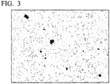
- an Al mapping image is obtained by performing Auger electron spectroscopy (AES) on the cross-sectional structure of the cBN sintered material.
- a portion of the Al compound in the obtained image is extracted by image processing, maximum lengths of respective particles are obtained by image analysis, and an average particle size is calculated based on the maximum lengths.
- the maximum length can be obtained by obtaining Feret diameters of each particle.
- Al compound particles that appear to be in contact with each other are separated from each other using a treatment of separating a portion where Al compound particles appear to be in contact with each other, for example, using watershed which is one image processing operation.
- a maximum length of each particle is obtained from the Al mapping image as the diameter of each particle. Based on the volume of each particle that is calculated from the above diameter, a graph in which the vertical axis represents the volume percentage [%] and the horizontal axis represents the diameter [ ⁇ m] is drawn. A value corresponding to a volume percentage of 50% is obtained as an average particle size of the Al compound in one image, and an average value of values that are obtained by processing at least three images in an Al mapping image obtained by AES at a magnification of 20000 is obtained as an average particle size [ ⁇ m] of the Al compound. During the particle analysis, a length ( ⁇ m) per pixel is set using a scale value obtained by AES in advance. A visual field region of about 5.0 ⁇ m ⁇ 3.0 ⁇ m is desirable as an observation region used for the image processing.
- the ratio of the content S N of nitrogen (N) included in the Al compound to the content So of oxygen (O) included in the Al compound (a value of S N /S O ; an area ratio) is 1.1 to 5 and preferably 2 to 4.5.
- a ratio S N1 /S O1 of a content S N1 of nitrogen (N) included in the Al compound to a content S O1 of oxygen (O) included in the Al compound is calculated.
- An average value of values obtained by processing at least three images is obtained as the ratio S N /S O (area ratio) of the content S N of nitrogen (N) included in the Al compound to the content So of oxygen (O) included in the Al compound.
- a visual field region of about 5.0 ⁇ m ⁇ 3.0 ⁇ m is desirable as an observation region used for the image processing.
- cBN particles having pre-treated surfaces were used as a cBN raw material.
- an AlN film was formed on the cBN particle surfaces using an ALD method.
- a fluidized bed was charged with the cBN particles, the inside of the furnace was heated to about 350°C, and one cycle was repeated until a desired AlN film thickness was obtained, the cycle including an Ar+Al(CH 3 ) 3 gas inflow step, an Ar gas purge step, an Ar+NH 3 gas inflow step, and an Ar gas purge step.
- the AlN film having a thickness of about 10 nm was able to be coated and formed on the cBN particle surfaces.
- the cBN particles having the surfaces on which the AlN film having the desired thickness was formed were heated in a vacuum at about 1000°C such that impurity elements such as oxygen on the cBN surface were diffused into the AlN film and were captured in the AlN film.
- the AlN film in which the impurity elements were captured were peeled off from the cBN surfaces due to ball mill mixing after the heat treatment.
- cBN particles having a high surface cleanliness from which the impurity components such as oxygen adsorbed on the cBN surfaces were removed were able to be obtained.
- cBN particles in which the thickness of the AlN film was 10 nm and cBN particles in which the thickness of the AlN film was 35 nm were prepared, respectively, and were heated in a vacuum at about 1000°C. As a result, cBN powders with the AlN film were obtained. Regarding the cBN powder in which the thickness of the AlN film was 10 nm, a heat treatment at about 400°C was performed in addition to the heat treatment at about 1000°C. As a result, cBN powders with the AlN film having different surface cleanlinesses were obtained.
- the cBN particle powder having an average particle size of 0.5 ⁇ m or less that was pre-treated as described above and TiN powder, TiC powder, Al powder, TiAl 3 powder, Al 2 O 3 powder, and Si 3 N 4 powder having an average particle size in a range of 0.3 to 0.9 ⁇ m were prepared as base powders for forming a binder phase.
- Some base powders selected from the base powders and the cBN particle powder were blended such that a content ratio of the cBN particle powder was 35 to 80 vol% with respect to the total amount of the powders as 100 vol%, were mixed with each other in a wet process, and were dried.
- this mixed powder was press-molded by hydraulic pressing into a green compact having a diameter of 50 mm and a thickness of 1.5 mm at a molding pressure of 1 MPa.
- this green compact underwent a heat treatment by being held at a predetermined temperature in a range of 1000°C to 1300°C in a vacuum atmosphere under a pressure of 1 Pa for 30 to 60 minutes.
- the green compact on which the above-described heat treatment was performed was superimposed on a support piece made of WC-based cemented carbide including 8 mass% of Co and a balance of WC and having a diameter of 50 mm and a thickness of 2 mm that was prepared separately.
- the green compact was charged into a typical ultra-high pressure sintering apparatus and was sintered under typical conditions of pressure: 3 to 10 GPa, for example, 5 GPa, temperature: 1400°C, and holding time: 30 minutes.
- cBN sintered materials 1 to 15 according to the present invention (hereinafter, also referred to as "sintered materials according to the present invention") shown in Table 2 were prepared.
- the heat treatment was performed on the green compact mainly in order to remove a solvent during the wet mixing.
- the oxidation of the base powders is prevented in the steps until the ultra-high pressure sintering.
- the base powders were handled in a non-oxidation protective atmosphere.
- cBN particle powder having an average particle size of 0.5 ⁇ m or less that was pre-treated as shown in Table 1 cBN particle powder having an average particle size of about 1.5 ⁇ m or less that was prepared under conditions other than the conditions defined in the present invention, TiN powder, TiC powder, Al powder, TiAl 3 powder, Al 2 O 3 powder, AlN powder, and Si 3 N 4 powder having an average particle size in a range of 0.3 to 0.9 ⁇ m that were base powders for forming a binder phase, cBN particle powder having an average particle size of 0.5 ⁇ m or less that was not heated, and TiN powder, TiC powder, Al powder, TiAl 3 powder, Al 2 O 3 powder, AlN powder, and Si 3 N 4 powder having an average particle size in a range of 0.3 to 0.9 ⁇ m that were base powders for forming a binder phase were prepared.
- Some base powders selected from the base powders and the cBN particle powder were blended such that a content ratio of the cBN particle powder was 21 to 85 vol% with respect to the total amount of the powders as 100 vol%, were mixed with each other in a wet process, and were dried.
- a green compact was prepared under the same conditions as those of the sintered materials 1 to 15 according to the present invention and was heated.
- This green compact was sintered under an ultrahigh pressure at a high temperature under the same conditions as those of sintered materials 1 to 15 according to the present invention.
- cBN sintered materials according to Comparative Examples hereinafter, referred to as "comparative sintered materials” 1 to 11 shown in Table 3 were prepared.
- the comparative sintered materials 1 to 5 were cBN sintered materials in which base powders that were not heated were used.
- the comparative sintered materials 6 and 11 were cBN sintered materials in which the cBN content was outside of the condition defined in the present invention.
- the comparative sintered materials 7 and 9 were cBN sintered materials in which the proportion of Al or the Al compound in the base powders was adjusted such that the content of the Al compound in the cBN sintered materials was outside of the condition defined in the present invention.
- the comparative sintered material 8 was a cBN sintered material in which the cBN particle size was outside of the condition defined in the present invention.
- the comparative sintered material 10 is a cBN sintered material in which the proportion of AlN in the base powders was increased such that the ratio S N /S O of the content S N of nitrogen (N) included in the Al compound of the binder phase of the cBN sintered material to the content So of oxygen (O) included in the Al compound of the binder phase of the cBN sintered material was outside of the condition defined in the present invention.
- [Table 1] Kind Pre-Treatment Conditions of cBN Base Powder Thickness of AlN Film formed on cBN Particles using ALD (nm) Heat Treatment Conditions of cBN Particles with AlN Film Heat Treatment Temperature (°C) Heat Treatment Time (min) A 10 1000 60 B 35 C 10 400
- an Al mapping image, a nitrogen (N) mapping image, and an oxygen (O) mapping image are obtained using Auger electron spectroscopy (AES) to measure the content ratio of Al in the binder phase of the cBN sintered material, the average particle size of the Al compound in the binder phase, and the ratio S N /S O (area ratio) of the content S N of nitrogen (N) in the Al compound to the content S O of oxygen (O) in the Al compound.
- AES Auger electron spectroscopy
- the binder phase composition of the cBN sintered material was measured by X-ray diffraction (XRD) analysis.
- the cross-sectional structure of the cBN sintered material was observed with a SEM to obtain a secondary electron image.
- a portion of the cBN particles in the obtained image was binarized and extracted by image processing as illustrated in FIG. 1 , and a maximum length of each of the cBN particles is obtained by image analysis as a diameter of the cBN particle.
- a graph in which the vertical axis represents the cumulative volume percentage (vol%) and the horizontal axis represents the diameter ( ⁇ m) is drawn.
- a value corresponding to a cumulative volume percentage of 50% was obtained as a particle size of the cBN particles, and an average value of values that were obtained by processing at least three images in a secondary electron image obtained by observation using a SEM at a magnification of 20000 is obtained as an average particle size [ ⁇ m] of the cBN particles.
- each of the sintered materials 1 to 15 according to the present invention and the comparative sintered materials 1 to 11 were polished using a diamond grindstone, and were split using a wire-electrical discharge machining device. Further, the split portions of the sintered material were brazed to brazing portions (corner portions) of an insert body made of WC-based cemented carbide including 5 mass% of Co, 5 mass% of TaC, and a balance of WC and having a shape according to ISO CNGA 120408 using a brazing material of an Ag alloy including 26 mass% of Cu, 5 mass% of Ti, and a balance of Ag. Further, the upper and lower surfaces and the outer periphery were polished and horned.
- cBN sintered material cutting tools 1 to 15 according to the present invention (hereinafter, also referred to as “tools according to the present invention") and cBN sintered material cutting tools 1 to 11 according to Comparative Examples (hereinafter, referred to as “comparative tools”) having an insert shape according to ISO CNGA 120408 were prepared.
- each of the various cutting tools was screwed and fixed to a tip portion of an insert holder of tool steel using a fixing jig.
- an intermittent cutting test was performed under the following cutting conditions.
- Work material a round bar made of carbolized steel (hardness: HRC 61) according to JIS SCr420 with eight longitudinal grooves formed at equal intervals in the longitudinal direction Cutting speed: 200 m/min Depth of cut: 0.10 mm Feed rate: 0.10 mm/rev Condition: dry
- the number of times of intermittent cutting was counted until chipping or fracturing occurs on an edge tip of the cutting tool, and was evaluated for tool life.
- the edge tip was observed every 500 times of intermittent cutting to determine whether or not fracturing occurred on the edge tip.
- Table 4 shows the test results.
- [Table 4] Kind Tool Life (Number of Times of Intermittent Cutting) Kind Tool Life (Number of Times of Intermittent Cutting) Tool 1 according to Present invention Chipping (2,000) Comparative Tool 1 Fracturing (500) Tool 2 according to Present invention Chipping (14,000) Comparative Tool 2 Fracturing (500) Tool 3 according to Present invention Chipping (15,000) Comparative Tool 3 Fracturing (1,000) Tool 4 according to Present invention Chipping (14,000) Comparative Tool 4 Fracturing (1,000) Tool 5 according to Present invention Chipping (5,000) Comparative Tool 5 Chipping (1,500) Tool 6 according to Present invention Chipping (5,000) Comparative Tool 6 Fracturing (500) Tool 7 according to Present invention Chipping (7,000) Comparative Tool 7 Fracturing (500) Tool 8 according to Present invention Chipping (8,000) Comparative Tool 8 Fracturing (1,000) Tool 9 according to Present invention Chipping (7,500) Comparative Tool 9 Fracturing (1,000) Tool 10 according to Present invention Chipping (8,500) Comparative Tool 10 Fracturing (500
- the average particle size of the cBN particles was 0.5 ⁇ m
- the content ratio of the cBN particles in the cBN sintered material was 35 vol% to 80 vol%
- the binder phase included 1.0 vol% to 20 vol% of the Al compound
- the average particle size of the Al compound present in the binder phase was 300 nm or less
- the value of S N /S O (area ratio) was 1.1 to 5. Therefore, the initiation or propagation of cracks from the Al compound particles was less likely to occur, a local and excessive reaction between the cBN particles and the binder phase in the sintered material was suppressed, and the amount of an oxide was small. Therefore, the interfacial adhesion strength between the cBN particles and the binder phase was improved, and the toughness was excellent.
- the tool life was long during cutting of high hardness steel where the edge tip was at a high temperature and under a high load, only chipping occurred and critical fracturing did not occur on the edge tip, and excellent toughness and fracturing resistance were exhibited.
- the cBN tool according to the present invention has excellent fracturing resistance, and thus is applicable not only to cutting of high hardness steel but also to cutting under various cutting conditions.
- the cBN tool according to the present invention can satisfactorily cope with the improvement of the performance of cutting apparatuses, power saving and energy saving during cutting, and a reduction in costs.
Landscapes
- Chemical & Material Sciences (AREA)
- Engineering & Computer Science (AREA)
- Ceramic Engineering (AREA)
- Manufacturing & Machinery (AREA)
- Materials Engineering (AREA)
- Structural Engineering (AREA)
- Organic Chemistry (AREA)
- Crystallography & Structural Chemistry (AREA)
- Inorganic Chemistry (AREA)
- Mechanical Engineering (AREA)
- Cutting Tools, Boring Holders, And Turrets (AREA)
- Ceramic Products (AREA)
Applications Claiming Priority (2)
| Application Number | Priority Date | Filing Date | Title |
|---|---|---|---|
| JP2016102676 | 2016-05-23 | ||
| PCT/JP2017/019010 WO2017204152A1 (fr) | 2016-05-23 | 2017-05-22 | Outil de coupe fait d'un corps fritté en nitrure de bore cubique |
Publications (2)
| Publication Number | Publication Date |
|---|---|
| EP3466573A1 true EP3466573A1 (fr) | 2019-04-10 |
| EP3466573A4 EP3466573A4 (fr) | 2020-01-22 |
Family
ID=60411284
Family Applications (1)
| Application Number | Title | Priority Date | Filing Date |
|---|---|---|---|
| EP17802744.7A Withdrawn EP3466573A4 (fr) | 2016-05-23 | 2017-05-22 | Outil de coupe fait d'un corps fritté en nitrure de bore cubique |
Country Status (5)
| Country | Link |
|---|---|
| US (1) | US11130713B2 (fr) |
| EP (1) | EP3466573A4 (fr) |
| JP (1) | JP6826326B2 (fr) |
| CN (1) | CN109070236B (fr) |
| WO (1) | WO2017204152A1 (fr) |
Cited By (2)
| Publication number | Priority date | Publication date | Assignee | Title |
|---|---|---|---|---|
| EP3596244A1 (fr) * | 2017-03-15 | 2020-01-22 | Element Six (UK) Limited | Matériau de nitrure de bore cubique polycristallin fritté |
| US12194546B2 (en) | 2020-09-16 | 2025-01-14 | Board Of Trustees Of Michigan State University | Cubic boron nitride inserts, related methods, and related apparatus |
Families Citing this family (5)
| Publication number | Priority date | Publication date | Assignee | Title |
|---|---|---|---|---|
| JP7137119B2 (ja) * | 2018-07-02 | 2022-09-14 | 三菱マテリアル株式会社 | cBN焼結体および切削工具 |
| JP7096977B2 (ja) * | 2018-09-28 | 2022-07-07 | 三菱マテリアル株式会社 | cBN焼結体および切削工具 |
| JP7161670B2 (ja) * | 2018-10-09 | 2022-10-27 | 三菱マテリアル株式会社 | 立方晶窒化ほう素基焼結体および切削工具 |
| CN111057925B (zh) * | 2019-12-31 | 2021-08-20 | 富耐克超硬材料股份有限公司 | 聚晶金刚石立方氮化硼复合片及其制备方法 |
| WO2022091257A1 (fr) * | 2020-10-28 | 2022-05-05 | 住友電工ハードメタル株式会社 | Corps fritté en nitrure de bore cubique, outil comprenant un corps fritté en nitrure de bore cubique et procédé de production d'un corps fritté en nitrure de bore cubique |
Family Cites Families (15)
| Publication number | Priority date | Publication date | Assignee | Title |
|---|---|---|---|---|
| JPH061666A (ja) * | 1992-06-18 | 1994-01-11 | Kyocera Corp | 立方晶窒化硼素質焼結体およびその製造方法 |
| JP2000247746A (ja) * | 1999-02-26 | 2000-09-12 | Kyocera Corp | 立方晶窒化硼素質焼結体切削工具 |
| JP4558042B2 (ja) * | 2005-04-14 | 2010-10-06 | 住友電工ハードメタル株式会社 | cBN焼結体、及びそれを用いた切削工具 |
| US8124553B2 (en) * | 2007-01-30 | 2012-02-28 | Sumitomo Electric Hardmetal Corp. | Composite sintered body |
| JP2011189421A (ja) | 2010-03-12 | 2011-09-29 | Sumitomo Electric Hardmetal Corp | 立方晶窒化硼素焼結体工具 |
| JP5305056B1 (ja) * | 2012-05-16 | 2013-10-02 | 三菱マテリアル株式会社 | 立方晶窒化ほう素基焼結体製切削工具 |
| JP6032409B2 (ja) * | 2012-10-26 | 2016-11-30 | 三菱マテリアル株式会社 | 立方晶窒化ほう素基超高圧焼結体を工具基体とする切削工具、表面被覆切削工具 |
| JP5988430B2 (ja) * | 2012-10-26 | 2016-09-07 | 住友電工ハードメタル株式会社 | 立方晶窒化ホウ素焼結体およびその製造方法 |
| GB201307800D0 (en) * | 2013-04-30 | 2013-06-12 | Element Six Ltd | PCBN material, method for making same, tools comprising same and method of using same |
| US9950962B2 (en) | 2013-10-22 | 2018-04-24 | Tungaloy Corporation | Cubic boron nitride sintered body and coated cubic boron nitride sintered body |
| CN104858458B (zh) * | 2014-02-26 | 2018-09-14 | 三菱综合材料株式会社 | 耐异常损伤性和耐磨损性优异的表面包覆切削工具 |
| JP6637664B2 (ja) * | 2014-03-28 | 2020-01-29 | 三菱マテリアル株式会社 | 立方晶窒化硼素焼結体切削工具 |
| WO2016084929A1 (fr) * | 2014-11-27 | 2016-06-02 | 三菱マテリアル株式会社 | Objet fritté à base de nitrure de bore cubique et outil coupant constitué d'un objet fritté à base de nitrure de bore cubique |
| JP6853951B2 (ja) * | 2017-03-01 | 2021-04-07 | 三菱マテリアル株式会社 | cBN焼結体および切削工具 |
| JP7015979B2 (ja) * | 2018-03-14 | 2022-02-04 | 三菱マテリアル株式会社 | cBN焼結体および切削工具 |
-
2017
- 2017-05-22 EP EP17802744.7A patent/EP3466573A4/fr not_active Withdrawn
- 2017-05-22 JP JP2017540291A patent/JP6826326B2/ja active Active
- 2017-05-22 CN CN201780027452.0A patent/CN109070236B/zh active Active
- 2017-05-22 WO PCT/JP2017/019010 patent/WO2017204152A1/fr not_active Ceased
- 2017-05-22 US US16/303,540 patent/US11130713B2/en active Active
Cited By (2)
| Publication number | Priority date | Publication date | Assignee | Title |
|---|---|---|---|---|
| EP3596244A1 (fr) * | 2017-03-15 | 2020-01-22 | Element Six (UK) Limited | Matériau de nitrure de bore cubique polycristallin fritté |
| US12194546B2 (en) | 2020-09-16 | 2025-01-14 | Board Of Trustees Of Michigan State University | Cubic boron nitride inserts, related methods, and related apparatus |
Also Published As
| Publication number | Publication date |
|---|---|
| WO2017204152A1 (fr) | 2017-11-30 |
| CN109070236B (zh) | 2020-07-03 |
| JPWO2017204152A1 (ja) | 2019-05-16 |
| US11130713B2 (en) | 2021-09-28 |
| EP3466573A4 (fr) | 2020-01-22 |
| US20200317584A1 (en) | 2020-10-08 |
| CN109070236A (zh) | 2018-12-21 |
| JP6826326B2 (ja) | 2021-02-03 |
Similar Documents
| Publication | Publication Date | Title |
|---|---|---|
| US11130713B2 (en) | Cubic boron nitride sintered material cutting tool | |
| JP6637664B2 (ja) | 立方晶窒化硼素焼結体切削工具 | |
| JP5305056B1 (ja) | 立方晶窒化ほう素基焼結体製切削工具 | |
| JP5614460B2 (ja) | cBN焼結体工具および被覆cBN焼結体工具 | |
| EP3225337B1 (fr) | Outil de coupe à revêtement de surface présentant une excellente résistance à l'écaillage et une excellente résistance à l'usure | |
| JP6343888B2 (ja) | 耐欠損性にすぐれた立方晶窒化硼素焼結体切削工具 | |
| EP2752265B1 (fr) | Outil de coupe constitué d'un matériau fritté à base de nitrure de bore cubique | |
| EP2631027B1 (fr) | Corps fritté en nitrure de bore cubique et outil associé | |
| WO2016104563A1 (fr) | Corps fritté en nitrure de bore cubique et corps fritté en nitrure de bore cubique revêtu | |
| JP6032409B2 (ja) | 立方晶窒化ほう素基超高圧焼結体を工具基体とする切削工具、表面被覆切削工具 | |
| JP6575858B2 (ja) | 耐欠損性にすぐれた立方晶窒化硼素焼結体切削工具 | |
| JP7235200B2 (ja) | 超硬合金および切削工具 | |
| JP6198142B2 (ja) | 立方晶窒化ホウ素基超高圧焼結材料製切削工具 | |
| KR20090101383A (ko) | 입방정 질화붕소기 초고압 소결재료로 만든 절삭 팁 | |
| JP6968341B2 (ja) | 微細構造組織を有する立方晶窒化ほう素基焼結体および切削工具 | |
| JP2004026555A (ja) | 立方晶窒化ホウ素含有焼結体およびその製造方法 | |
| JP5407487B2 (ja) | 表面被覆切削工具 | |
| JPS644988B2 (fr) | ||
| JP4070417B2 (ja) | 窒化珪素質部材及びその製造方法並びに切削工具 | |
| JP7096977B2 (ja) | cBN焼結体および切削工具 | |
| EP3202750A1 (fr) | Corps fritté, outil de coupe utilisant un corps fritté et procédé de fabrication de corps fritté | |
| JP7015979B2 (ja) | cBN焼結体および切削工具 | |
| KR20210126568A (ko) | cBN 소결체 및 절삭 공구 | |
| JPH0225871B2 (fr) | ||
| JP2022142894A (ja) | cBN焼結体 |
Legal Events
| Date | Code | Title | Description |
|---|---|---|---|
| STAA | Information on the status of an ep patent application or granted ep patent |
Free format text: STATUS: THE INTERNATIONAL PUBLICATION HAS BEEN MADE |
|
| PUAI | Public reference made under article 153(3) epc to a published international application that has entered the european phase |
Free format text: ORIGINAL CODE: 0009012 |
|
| STAA | Information on the status of an ep patent application or granted ep patent |
Free format text: STATUS: REQUEST FOR EXAMINATION WAS MADE |
|
| 17P | Request for examination filed |
Effective date: 20181121 |
|
| AK | Designated contracting states |
Kind code of ref document: A1 Designated state(s): AL AT BE BG CH CY CZ DE DK EE ES FI FR GB GR HR HU IE IS IT LI LT LU LV MC MK MT NL NO PL PT RO RS SE SI SK SM TR |
|
| AX | Request for extension of the european patent |
Extension state: BA ME |
|
| RAP1 | Party data changed (applicant data changed or rights of an application transferred) |
Owner name: MITSUBISHI MATERIALS CORPORATION |
|
| DAV | Request for validation of the european patent (deleted) | ||
| DAX | Request for extension of the european patent (deleted) | ||
| REG | Reference to a national code |
Ref country code: DE Ref legal event code: R079 Free format text: PREVIOUS MAIN CLASS: B23B0027140000 Ipc: C04B0035583100 |
|
| A4 | Supplementary search report drawn up and despatched |
Effective date: 20200103 |
|
| RIC1 | Information provided on ipc code assigned before grant |
Ipc: C04B 35/5831 20060101AFI20191218BHEP Ipc: C04B 35/645 20060101ALI20191218BHEP Ipc: B23B 27/14 20060101ALI20191218BHEP Ipc: C04B 35/626 20060101ALI20191218BHEP |
|
| STAA | Information on the status of an ep patent application or granted ep patent |
Free format text: STATUS: EXAMINATION IS IN PROGRESS |
|
| 17Q | First examination report despatched |
Effective date: 20230321 |
|
| STAA | Information on the status of an ep patent application or granted ep patent |
Free format text: STATUS: THE APPLICATION HAS BEEN WITHDRAWN |
|
| 18W | Application withdrawn |
Effective date: 20230609 |